1. Introduction
The Twin Wire Arc process is a common commercial thermal spray process. A Twin Wire Arc coating is applied using a spray torch, which brings two electrically energized feed stock wires together. When the wires cross, an arc, similar to a welding arc, forms between the wire tips and causes them to melt. A gas stream injected behind the arcing wire tips atomizes the molten feed stock material and propels it downstream. When molten droplets of the feed stock material encounter the substrate the droplets flatten, solidify, and form a coating containing the characteristic lamellar structure associated with thermal sprayed materials.
It is important to understand the relationships between process inputs and coating characteristics for the Twin Wire Arc Zinc process. This work has been undertaken to aid in operating condition design of the Twin Wire Arc Zinc process where a specific coating distribution is important. There are numerous occasions in which it is important to closely control the shape and distribution of a deposited coating. For example, high-performance and high-tolerance twin wire arc coatings are often required in boiler applications [
1] and in high-efficiency diesel engines [
2,
3]. The goal of this work, then, is twofold. First, to both quantitatively and qualitatively assess the relationships between coating properties and input parameters. Second, to explain the observable trends in view of the current base of thermal spray knowledge about the twin wire arc process. For this experiment, process operating conditions were varied and spatial characteristics of the deposited coating such as pattern spray area, pattern eccentricity, pattern flatness, and pattern deposition rate were measured. A two-level full factorial design of experiments was used to determine the effect of each process input on spray pattern and deposition rate.
2. Experimental Methods
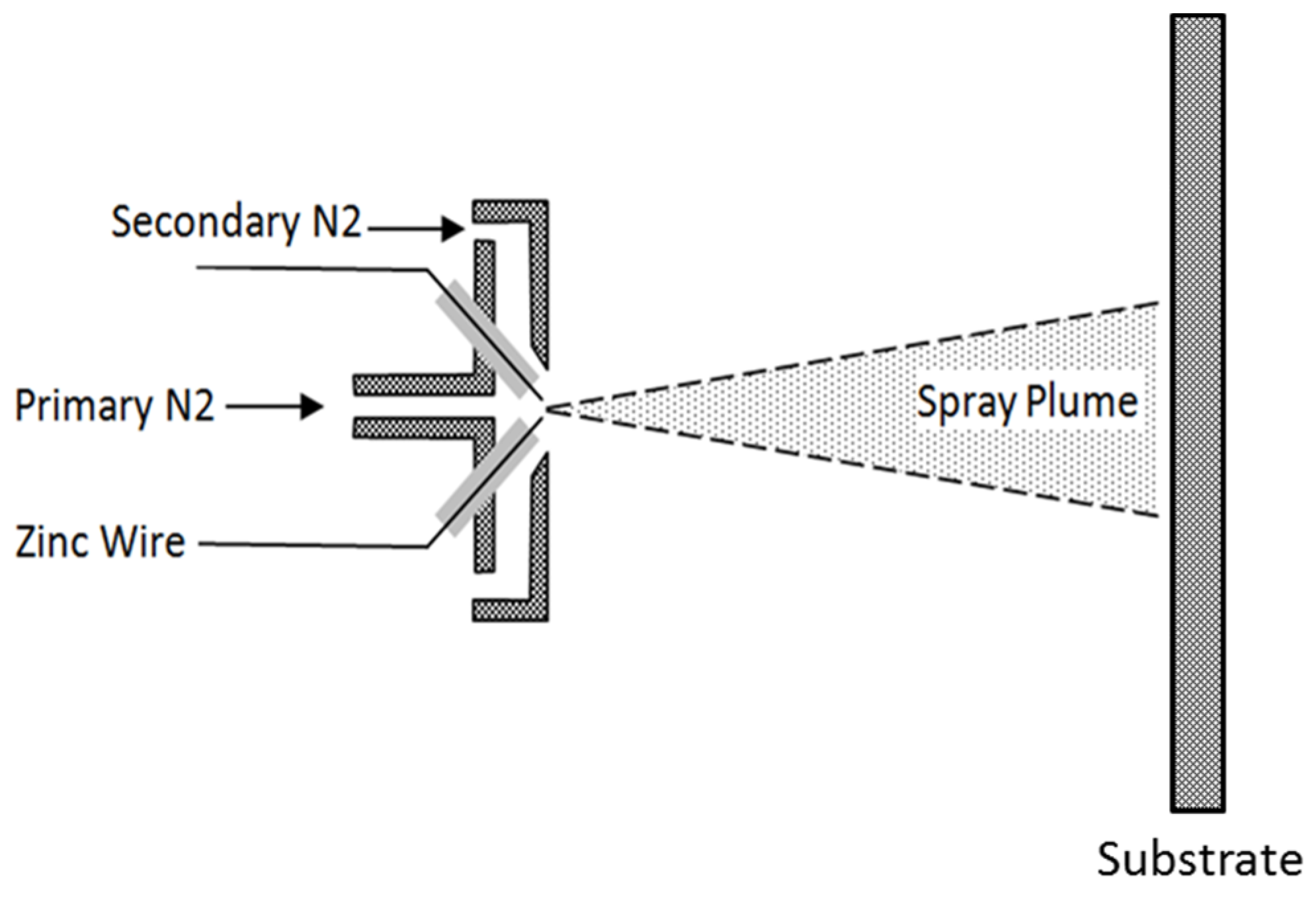
All spray experiments were conducted using a Praxair/TAFA 8835 (Concord, NH, USA) Twin Wire Arc torch spraying 1.58 mm (1/16 in) diameter 02Z Zinc wire (Praxair Surface Technologies, Inc.; Indianapolis, IN, USA) onto 6061 aluminum substrates. This particular arc spray torch incorporates a secondary atomizing gas stream. The working principal is shown schematically in
Figure 1. The torch was mounted on an ABB-IRB 6600 (Zurich, Switzerland) six axis robot which was used to position the torch and maintain a constant standoff distance of 46 cm (18 in).
Figure 1.
Schematic showing the torch working principal, general relationship between primary and secondary atomizing gases, and approximate substrate—spray plume relationship.
Figure 1.
Schematic showing the torch working principal, general relationship between primary and secondary atomizing gases, and approximate substrate—spray plume relationship.
Samples were grit blasted with MetcoLite F-24 Al2O3 grit (Sulzer-Metco; Wohlen, Switzerland) at 200 kPa (30 psi) pressure, 7.5 cm (3 in) standoff distance, and 45° angle of attack. After grit blasting, samples were cleaned with acetone, rinsed with isopropyl alcohol, and dried using compressed air.
A two-level full factorial designed experiment was conducted [
4] using the three process parameters: primary gas pressure, secondary gas pressure, and arc current as inputs. The data were taken in randomized order. All process equipment was reset between each spray run to avoid bias due to reuse of settings. Data was entered into Minitab
® (Minitab Inc., State College, PA, USA) for analysis.
Table 1 shows the range of operating parameters used for these experiments. These parameters were chosen based on the upper and lower limits for torch operation suggested by the manufacturer [
5]. Five center points with values of 30.5 cm (12 in) standoff, 259 kPa (37.5 psi) primary gas pressure, 207 kPa (30 psi) secondary gas pressure, and 150 Amps arc current were used. All spray runs were conducted in randomized order. All atomizing gas for the 8835 wire arc control panel was from a common nitrogen manifold held at 897 kPa (130 psi). All process equipment was reset between each spray run to avoid bias due to reuse of settings. Data was entered into Minitab
® for analysis.
Table 1.
Torch operating condition ranges.
Table 1.
Torch operating condition ranges.
| Process parameter | Low | High |
|---|
| Primary pressure | 173 kPa (25 psi) | 345 kPa (50 psi) |
| Secondary pressure | 139 kPa (20 psi) | 276 kPa (40 psi) |
| Arc current | 50 Amps | 250 Amps |
Characterization of plume shape was conducted in order to determine the relationship between process conditions and the diameter, shape, and spatial uniformity of the spray pattern. This was accomplished by spraying onto 23 cm × 23 cm × 1.27 cm thick (9 in × 9 in × ½ in) Aluminum substrates without moving the torch. This arrangement captured the entire spray pattern for analysis. The spray time for each plume shape experiment was varied based on the operating conditions, and ranged between 5 and 80 s.
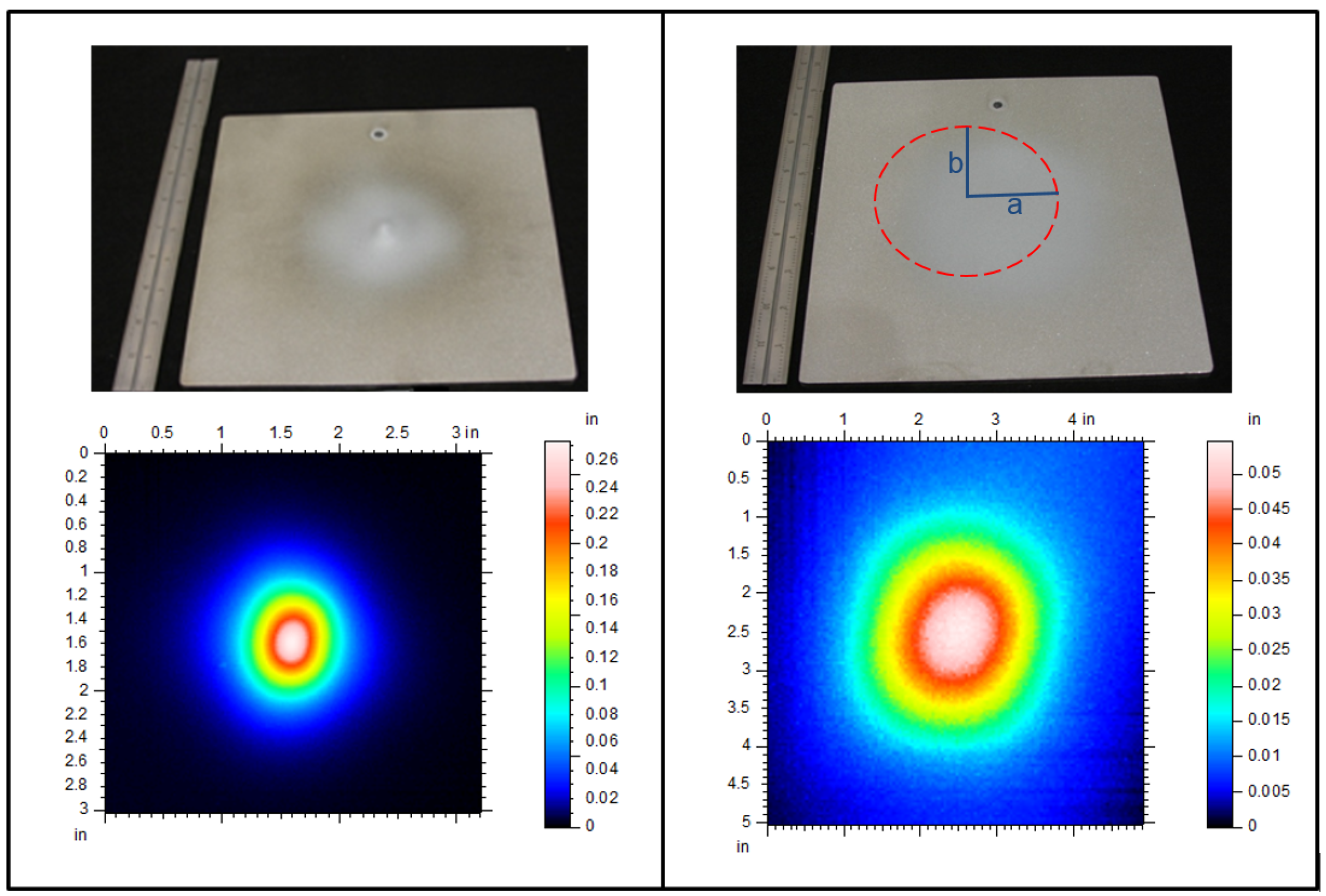
A Taylor Hobson Talysurf CLI 2000 (Taylor Hobson, Leicester, UK) high resolution surface profiling system was used to measure 3D surface topography and characterize each spray pattern. Each 23 cm × 23 cm plate was sprayed with a common torch orientation, and topography data was collected using a common plate orientation. Thus, all of the topography data sets have the same orientation relationship with respect to each other and the spray torch. A high-resolution 3D measurement of the coating surface was obtained for each plate, and the spray pattern position was defined with two orthogonal lines across the center of the spray pattern representing the major and minor axis of the spray pattern. These lines were chosen such that they were vertical and horizontal with respect to the spray torch orientation. It is possible that the positions of the major and minor plume axis used to determine pattern area were not oriented perfectly. However, this is of minimal concern because all of the plates were oriented similarly with respect to the torch, and any error associated with plate orientation will be consistent across the data. In addition, the spray patterns themselves are very circular, thus any error associated with identifying the major and minor plume axis is small. Two examples of sprayed substrates and their subsequent surface profiles are shown in
Figure 2. The two examples represent the range of variation in spray pattern area, flatness, and eccentricity.
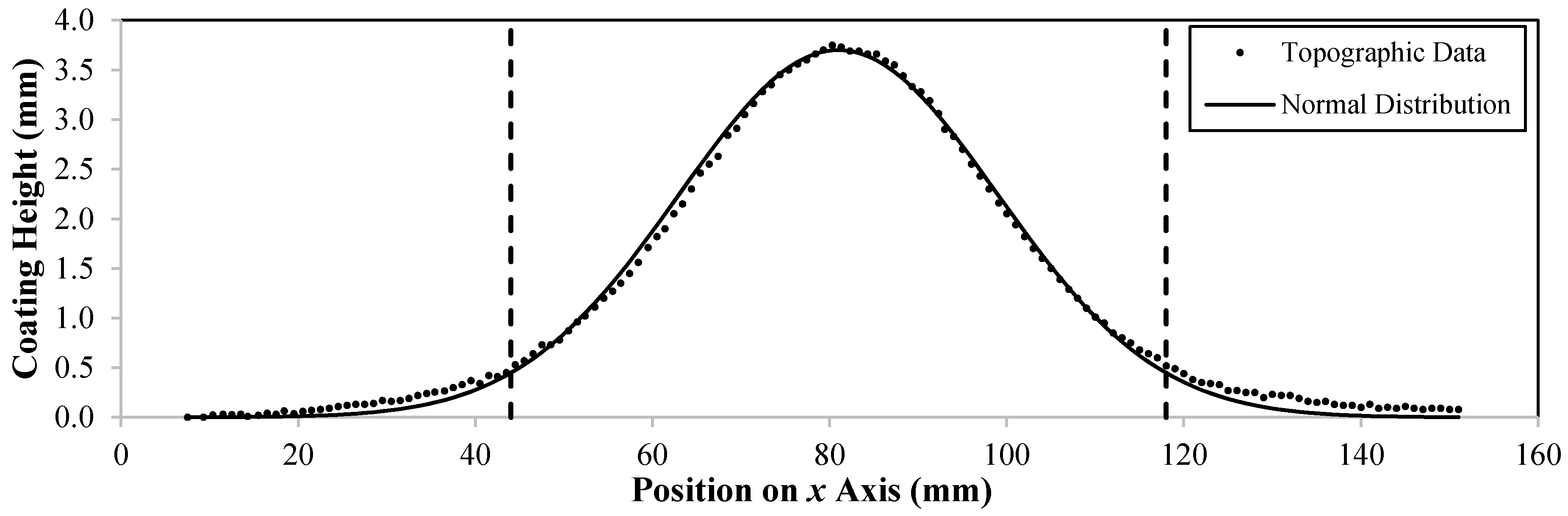
The spray area was determined by first fitting a normal distribution to the perpendicular cross-sections representing the major and minor axis of the spray pattern. Next, the standard deviation of both normal distributions was determined. Two standard deviations from the mean (2σ) was chosen as the outer edge of the spray pattern. Finally, the standard deviation was input into the equation for the area of an ellipse. A representative graph of this spray pattern cross section and fitted distribution is shown in
Figure 3. For the pattern cross section, the 95% pattern width (2σ) is from 44 to 118 mm (dotted lines), for a chord length of 72 mm.
Figure 2.
Spray pattern photos and raw surface topography data illustrating variation in spray pattern flatness and area observed in this study.
Figure 2.
Spray pattern photos and raw surface topography data illustrating variation in spray pattern flatness and area observed in this study.
Figure 3.
Representative surface topography plot with fitted normal distribution (vertical axis is exaggerated for clarity) to determine spray pattern characteristics.
Figure 3.
Representative surface topography plot with fitted normal distribution (vertical axis is exaggerated for clarity) to determine spray pattern characteristics.
Spray pattern eccentricity measures the non-circularity of the spray pattern according to Equation (1) where
b and
a are chords equal to half the length of each spray pattern axis (
Figure 2).
For example, the chord length of the pattern shown in
Figure 2 is 36 mm, half of the axis width of 72 mm. A spray pattern with high eccentricity will be elliptical in shape, while a spray pattern with low eccentricity will be more circular in shape.
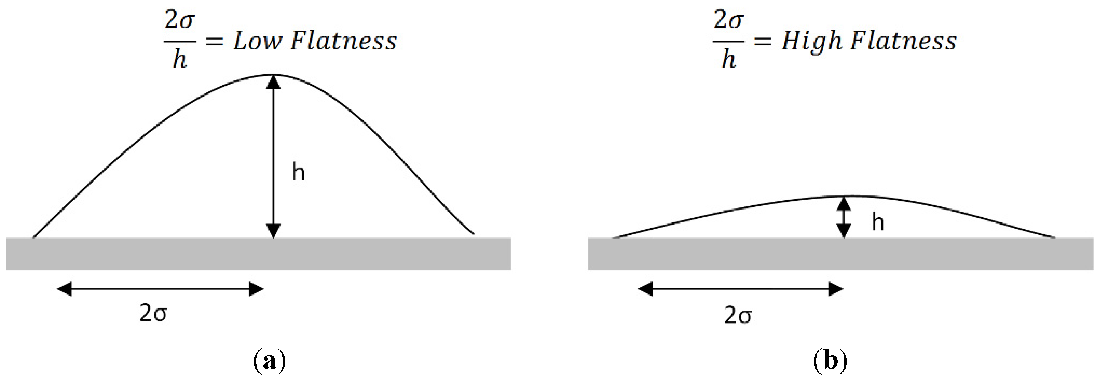
Spray pattern flatness was defined as the ratio of pattern chord width (2σ) to deposit thickness (
h), which is equivalent to the inverse of slope. Measuring spray pattern flatness is necessary to determine the uniformity of the spray pattern. All topographic data was normalized by spray time to ensure that the spray pattern thicknesses were comparable and could be accurately distinguished from substrate roughness by the surface profiler. A pattern with high flatness has a gentle slope and appears flat. A low flatness pattern has a steep slope and appears as a conical deposit, as shown in
Figure 4.
Figure 4.
Schematic representing (a) low and (b) high flatness spray patterns.
Figure 4.
Schematic representing (a) low and (b) high flatness spray patterns.
When normalized over time, the surface topography data gives deposition rate for each spray condition. The coating deposition rate was calculated by determining the ratio of pattern height at the torch centerline to spray time. Deposition rate was defined in this way to give a relative comparison of coating thickness deposited per unit time for each spray condition. This characterization is useful in determining how much material will be applied to specific areas for a given spray pattern.
3. Results and Discussion
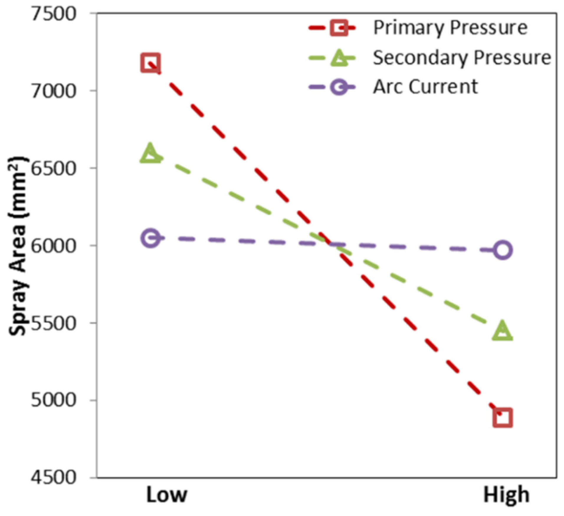
Spray pattern area varies significantly (α = 0.05, or 95% confidence level) with primary and secondary gas pressures, although not with arc current. The main effects for spray pattern area are shown graphically in
Figure 5. As primary and secondary gas pressure increases; pattern size decreases. Primary and secondary gas pressures both accelerate the particles. Secondary gas focuses the spray plume [
6]. Consider a particle in the spray plume with a given axial and radial velocity. The axial component of particle velocity (
Vp) is due to primary gas pressure, while the radial component is due to turbulence in the primary gas flow as it passes around the Zinc wires [
7]. Increasing gas pressures will result in a larger increase in the axial velocity component than in the radial velocity component of
Vp. Therefore, as either gas pressure increases, the particle will reach the substrate faster and will have less time to travel radially. Note that due to a low emissivity of molten Zink, it was not possible to measure
Vp. The above discussion is inferred from the effect of gas pressure on
Vp for other twin wire arc materials [
8,
9]. Arc current does not have a significant effect on spray pattern area. Since arc current affects wire feed rate, but has been shown to be unrelated to particle acceleration [
10], it may not be surprising that arc current has little effect on spray pattern shape.
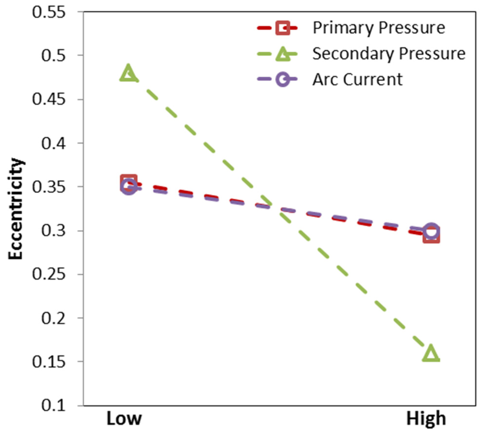
Spray pattern eccentricity was affected most by the secondary gas pressure, as shown in
Figure 6. A higher secondary gas pressure results in a lower pattern eccentricity, signifying a more circular pattern shape. This is a direct result of the torch design [
5]. Pattern eccentricity is caused by the presence of the wires in the primary gas stream. Flow around the wires perturbs the spray plume making it somewhat elliptical [
11]. Different melting behavior of the cathode and anode wires could also contribute to asymmetry of the spray plume [
7]. The secondary atomizing gas is delivered radially at a location slightly downstream from the wire tips. This radial gas flow tends to create a more circular pattern, overcoming the eccentricity caused by the Zinc wires. Primary gas pressure and arc current have little effect on pattern eccentricity, as expected [
12].
Figure 5.
Effect of primary gas pressure, secondary gas pressure, and arc current on pattern spray area. Dashed lines not meant to imply a linear relationship.
Figure 5.
Effect of primary gas pressure, secondary gas pressure, and arc current on pattern spray area. Dashed lines not meant to imply a linear relationship.
Figure 6.
Effect of primary gas pressure, secondary gas pressure, and arc current on pattern eccentricity. A more elliptical pattern has a large eccentricity. Dashed lines not meant to imply a linear relationship.
Figure 6.
Effect of primary gas pressure, secondary gas pressure, and arc current on pattern eccentricity. A more elliptical pattern has a large eccentricity. Dashed lines not meant to imply a linear relationship.
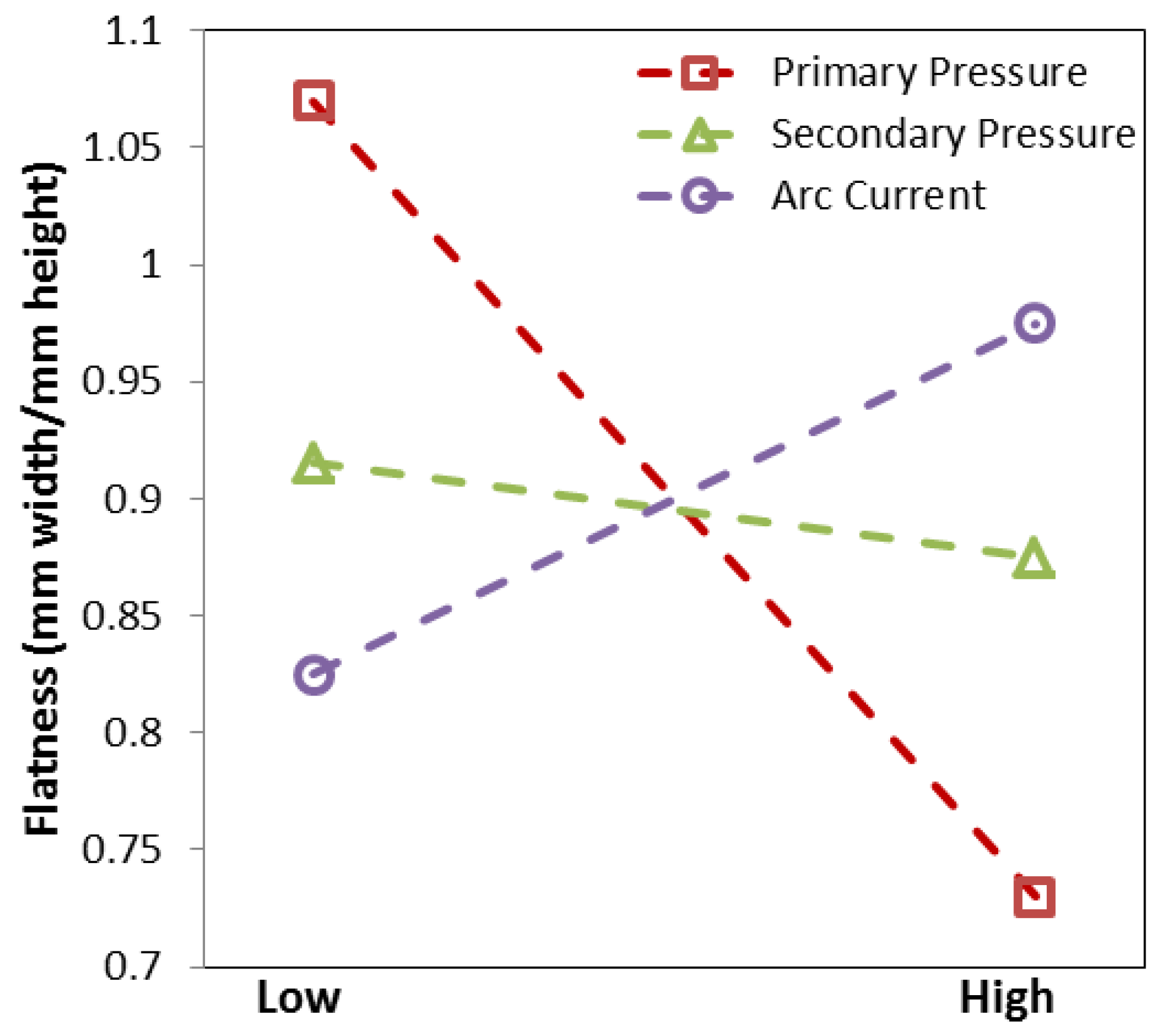
The effect of process parameters on pattern flatness is shown in
Figure 7. As primary gas pressure increases, flatness decreases. The reason increasing primary gas pressures reduces flatness is similar to the reason increasing primary gas pressure decreases pattern spray area. The radial component of
Vp is relatively unaffected by increasing primary gas pressure while the axial component of
Vp increases with increasing primary gas pressure. This causes the particles in the spray plume to concentrate near the center of the spray pattern resulting in a pattern with low flatness (high slope). Secondary gas pressure did not appreciably influence flatness. As arc current increases, flatness also increases, although it cannot be determined with the available data if this increase is statistically significant. The most flat surface is characterized by low primary gas pressure and high arc current.
Figure 7.
Effect of primary gas pressure, secondary gas pressure, and arc current on pattern flatness. A flat pattern has a high flatness. Dashed lines not meant to imply a linear relationship.
Figure 7.
Effect of primary gas pressure, secondary gas pressure, and arc current on pattern flatness. A flat pattern has a high flatness. Dashed lines not meant to imply a linear relationship.
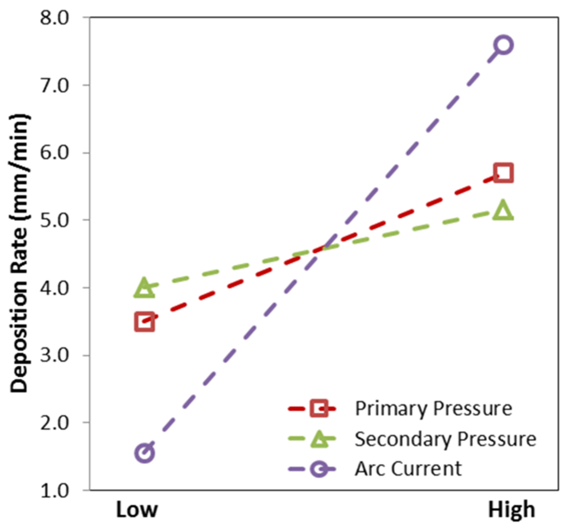
The effect of process parameters on deposition rate is shown in
Figure 8 where a high deposition rate is almost exclusively associated with a high arc current, with minor positive affect by high atomizing gas pressures. Arc current increases the wire feed rate, which results in more material reaching the substrate in a given time. Thus, deposition rate increases with increasing arc current. This is supported by reference [
13]. Deposition rate is related to deposition efficiency (DE), since the thickness measured was deposited on the substrate with efficiency equal to the DE. Previous research on the Twin Wire Arc Zinc process showed that DE increased with arc current [
14]. It follows, then, that deposition rate would increase with arc current. Atomizing gas pressures appear to have a minor effect on deposition rate, with primary gas pressure exhibiting a larger affect than secondary gas pressure. The same material sprayed over a larger area, as occurs with an increase in atomizing gas pressure, will result in a lower deposition rate. The large pattern spray areas resulting from low atomizing gas pressures can be correlated to low deposition rates. It can be shown then, that there is a direct relationship between pattern size and deposition rate when considering primary and secondary gas pressure, and that a spray condition cannot be reached with both maximum pattern size and maximum deposition rate.
Figure 8.
Effect of primary gas pressure, secondary gas pressure, and arc current on coating deposition rate. Note: dashed lines not meant to imply a linear relationship.
Figure 8.
Effect of primary gas pressure, secondary gas pressure, and arc current on coating deposition rate. Note: dashed lines not meant to imply a linear relationship.


