1. Introduction
Modern fabrication processes of integrated circuit (IC) and optoelectronic devices rely heavily on low-pressure plasma technology. A low pressure environment reduces the required applied voltage for igniting and sustaining plasma; however, vacuum chambers and pumps are required to maintain a low-pressure or vacuum during device processing. In low-pressure plasma technology, vacuum chambers and pumps are costly and require routine maintenance; furthermore, the allowed substrate size is limited by the chamber dimension. This has motivated the research and development of atmospheric-pressure plasma (APP) technology such as corona discharges, dielectric barrier discharge (DBD), and atmospheric-pressure plasma jets (APPJs) [
1,
2]. The main technical issue for the sustainment of glow discharge at a pressure of 1 atm is the high gas breakdown voltage and continuous arcing between electrodes. Recent jet designs offer promising plasma stability and have successfully prevented the continuous arcing problem [
3,
4,
5].
APP technology has been extensively applied in battery technology. Downstream H
2 APPs have been applied to reduce the surface layer of CuO to corresponding metals to improve the conductivity of the CuO-based anodes of batteries, thereby increasing the rate performance [
6]. Cyclonic APPs have been applied to treat the microporous polymer separator of a lithium-ion battery for improving hydrophilicity and for implanting functional groups; the battery performance was therefore improved [
7]. APPJs were also applied to directly deposit Li
4Ti
5O
12 (LTO) anode materials for lithium-ion batteries using a precursor salt solution containing Ti and Li ions [
8]. Ar/N
2 APPJs were used for post-treatment on LTO anodes of lithium-ion batteries for stable, high-rate performance [
9]. Owing to the strong interaction between N
2 APPJs and carbon-based materials, 1-min N
2 APPJ treatment on graphite felt electrodes can significantly improve the energy efficiency of an all-vanadium redox flow battery. The improved performance was attributed to improved electrochemical reactivity owing to the introduction of functional groups containing nitrogen and oxygen on the surfaces of graphite fibers [
10].
For applications of APPJs to solar cells, APPJ-deposited organosilicon was used as the seeding layer for the texturing of follow-up sputtered Ga-doped ZnO [
11,
12,
13,
14]. Cyclonic APPs were used to perform surface treatments on electrospun poly(vinylidenefluoride-
co-hexafluoropropylene) (PVDF-HFP) microfibrous membranes of DSSCs for improved efficiency [
15]. APPs with a designated process were used for the reduction of Pt counter electrodes [
16] and for the post surface treatments on TiO
2 photoanodes [
17,
18,
19] of DSSCs. A prolonged DBD treatment on TiO
2 was shown to improve DSSCs with low-temperature-sintered TiO
2 photoanodes [
20]. DSSCs with TiO
2 prepared by DBD jets with substrates heated by additional heaters have been successfully implemented [
21,
22]. A 30-min rf-APP has been used for the preparation of TiO
2 photoanodes of on-plastic DSSCs. APPs show strong oxidation effect to efficiently remove the organic binders in screen-printed TiO
2 pastes [
23]. An ultrafast (30 s–1 min) APPJ sintering process on nanoporous TiO
2 photoanodes of DSSCs has been promisingly developed; these DSSCs showed efficiency comparable to those fabricated by conventional furnace calcination process (510 °C × 15 min) [
24,
25,
26]. A similar APPJ sintering process was also applied for producing 3D reduced graphene oxide (rGO) nanosheet counter electrodes of DSSCs; the required processing time was only 11 s [
27].
In this paper, we first introduce a two-step ultrafast APPJ sintering process consisting of sequential screen-printing of nanosized particles with organic binders and APPJ rapid sintering. Optical emission spectroscopy analysis is used to determine endpoint of the APPJ-sintering process to prevent over-calcination. In this part, rapid APPJ-sintering on rGO pastes is given as an example. APPJ sintered oxides and 3D rGO nanosheets are implemented as the photoanodes and counter electrodes, respectively, of DSSCs. Finally, we describe rapid APPJ surface activation and modification on graphite felt electrodes of flow batteries to significantly enhance the battery performance.
2. Atmospheric-Pressure-Plasma-Jet Sintering Processes
APPJs have been extensively used in many fields as described in the Introduction section. Here, we describe a rapid APPJ sintering process for nanoporous materials. This process consists of two steps: the screen-printing of pastes consisting of the demanded nanosized materials and organic binders, and rapid sintering using APPJs. This procedure can be scaled up for a roll-to-roll process in which screen-printing is still frequently used for the second and follow-up layers owing to the alignment requirement [
28]. The sintering time for TiO
2 nanoparticles could be as short as 30 s with a substrate temperature of ~300 °C (heated by APPJs, no external heating source was used) [
24]. For producing porous rGO nanosheets, the sintering time was merely 11 s [
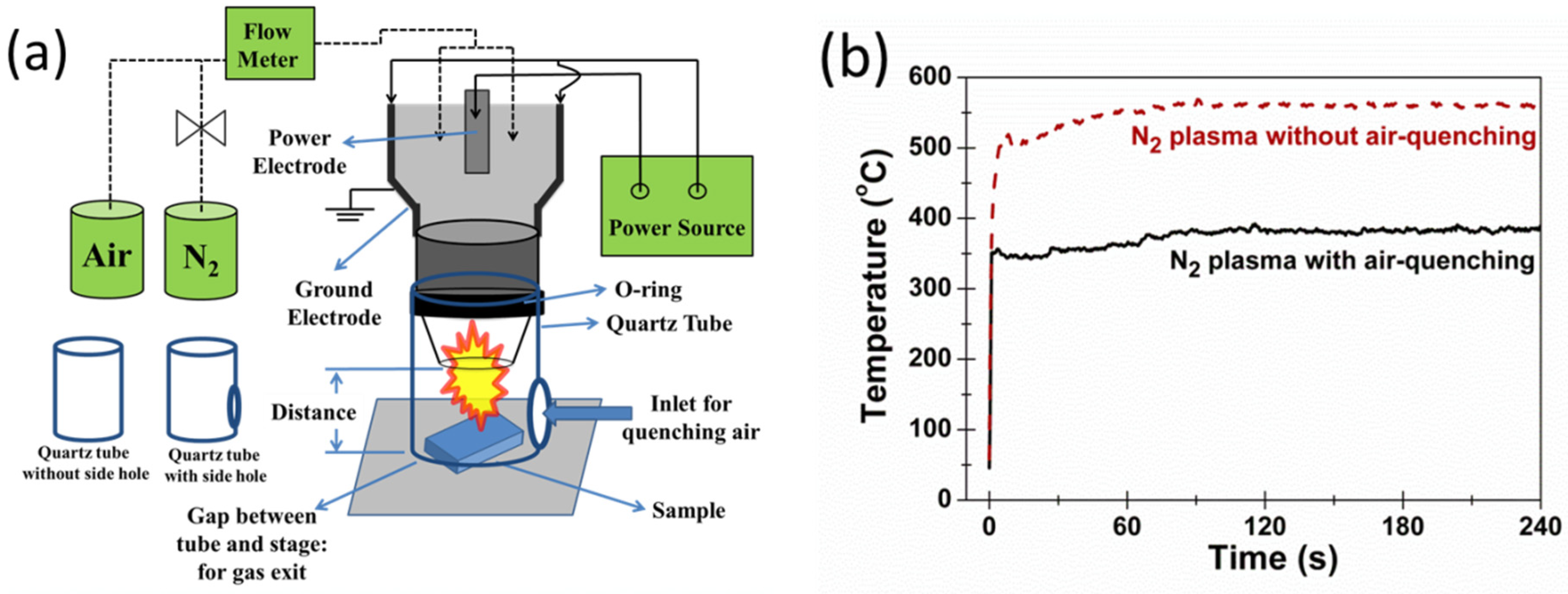
27]. The schematic of APPJ apparatus is shown in
Figure 1a. The plasma is generated by a power supply that can be of the DC pulse, AC, radio-frequency, or microwave types. Gas flows with high flow rate (usually >10 slm, depending on the jet design) are used to bring the plasmas to the open air while preventing continuous sparking or arcing problems. In our experiments, we use a quartz tube installed at the jet exit to confine the jet flow and to minimize the quenching effect from ambient air. In this fashion, the APPJ can expand and extend farther downstream [
29]. It is advised to leave a gap between the end of the quartz tube and the sample stage as the flow exit, making a smoother jet flow. The distance of the substrate from the jet exit can significantly influence the substrate temperature; the closer distance induces higher substrate temperature. The substrate temperature gradient along the substrate surface is more complicated and is related to the convective heat transfer. The gap of the quartz tube from the substrate also greatly influences the substrate temperature and substrate temperature gradient. When the treated materials are in an organic base, the involvement of oxidants in the APPJs can increase the oxidation rates of organic compounds [
23,
24,
30]. A hole on the side of the quartz tube is beneficial when treating materials containing organic compounds. The side hole can introduce ambient air in which oxygen can accelerate the oxidation rate of organics or metal-like materials [
24,
31]. When a quartz tube with a side hole is used, ambient air molecules will quench the highly energetic plasmas and lower the APPJ temperature.
Figure 1b shows the representative temperature evolution with and without air-quenching. A large temperature difference (~200 °C in this case) of N
2-APPJ heated substrates with and without air-quenching was identified [
24,
31]. Despite the reduction in temperature with air-quenching, the oxidation rates of organic compounds or metal-like materials are usually higher because of the involvement of oxygen in the reaction [
24,
31].
Figure 1.
(
a) Schematic of an atmospheric pressure plasma jet (APPJ) apparatus; (
b) representative substrate temperature evolutions with/without air-quenching [
31].
Figure 1.
(
a) Schematic of an atmospheric pressure plasma jet (APPJ) apparatus; (
b) representative substrate temperature evolutions with/without air-quenching [
31].
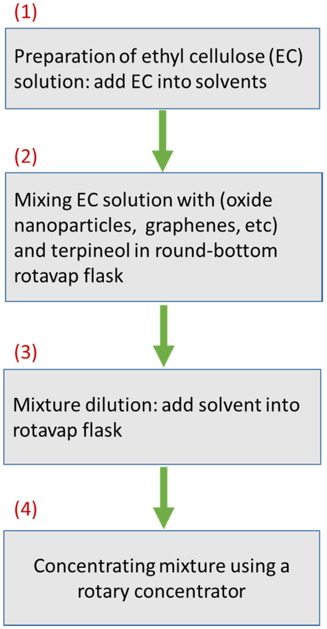
Figure 2 shows the flowchart of the typical preparation procedure of the pastes used for screen-printing. First, ethyl cellulose is mixed with solvents to make EC solutions (hereafter referred to as “EC”). EC is then mixed with terpineol and the desired nanosized oxides or carbon-based materials in a rotavap flask, followed by dilution with more solvents. Finally, the mixture is concentrated using a rotary concentrator.
Figure 2.
Preparation of pastes used for screen-printing.
Figure 2.
Preparation of pastes used for screen-printing.
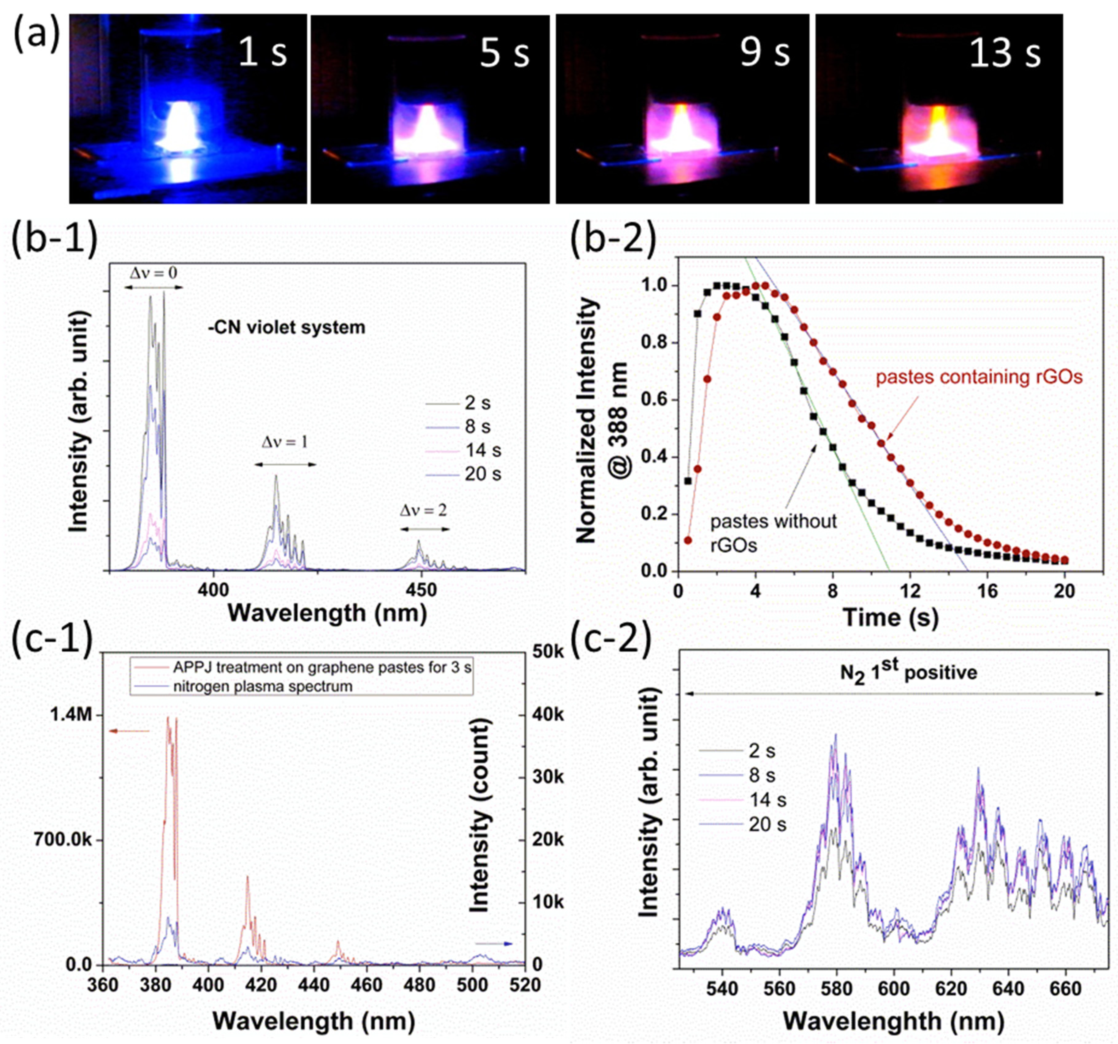
Figure 3 shows the representative optical emission spectra (OES) and snapshots of APPJs during the APPJ-sintering processes for rGO pastes [
27]. It is noted that the case is simpler when sintering screen-printed pastes containing oxide nanoparticles instead of rGOs because the main reaction occurs between the APPJs and organic binders only. For sintering rGO pastes by APPJs, we need to take into account the difference between the reaction rates of rGOs and organic binders lest the over-burning on rGOs.
Figure 3a shows the snapshots of APPJs at sintering times of 1, 5, 9, and 13 s. The color was initially bluish, then turning to pink and slightly yellowish as the sintering time increased.
Figure 3b-1 shows the evolution of the spectra in the wavelength range between 375 and 475 nm. The emissions at around 388, 414, and 450 nm are attributed to the CN violet system (B
2Σ→X
2Σ). The CN emissions were initially very strong, resulting in the bluish plasma color. As the sintering time increased, the amount of carbon-based materials (both rGOs and organic binders) decreased, leading to reduced intensity of CN emissions (some remained because N
2 2nd positive emissions, which have weaker intensities as indicated by the scales of vertical axes, partly overlap with CN emissions as shown in
Figure 3c-1. Therefore, the plasma color became yellowish or pinkish owing to the persistent N
2 1st positive emissions at wavelengths longer than 530 nm (
Figure 3c-2).
Figure 3.
APPJ sintering on reduced graphene oxide (rGO) pastes. (a) Snap shots of APPJs during operation; (b-1) OES spectra of CN violet system, (b-2) evolutions of normalized intensities of 388 nm emission for APPJ sintering on pastes with and without rGOs; (c-1) OES spectra taken for bare N2-APPJ (no rGO pastes) and taken during N2-APPJ sintering on rGO pastes after 3 s, and (c-2) OES spectra of N2 1st positive emissions taken during N2-APPJ sintering on rGO pastes.
In order to specify the effects of APPJ sintering on rGOs and organic binders, we prepared two different pastes with and without rGO powders but maintaining the same amount of ethyl cellulose, α-terpineol, and ethanol in them. By inspecting the evolution of the intensity from 388-nm CN emission during APPJ sintering, the comparison of the normalized intensities is plotted in
Figure 3b-2. In the case of APPJ sintering on pastes without rGOs, the normalized intensity increased more rapidly at the initial stage and decayed at an earlier time. On the other hand, for APPJ sintering on pastes with rGOs, the normalized intensity increased at a slower speed and decayed later. By linearly fitting the falling edges of the intensity curves and extrapolating them to the time axis, the intercepts indicate ~11 s and ~15 s in the cases without and with rGOs, respectively. Eleven seconds is suggested as the required duration for the nearly complete burnout of organic binders with some remnant rGOs in the format of 3D nanosheets, as shown in the SEM images in
Figure 4.
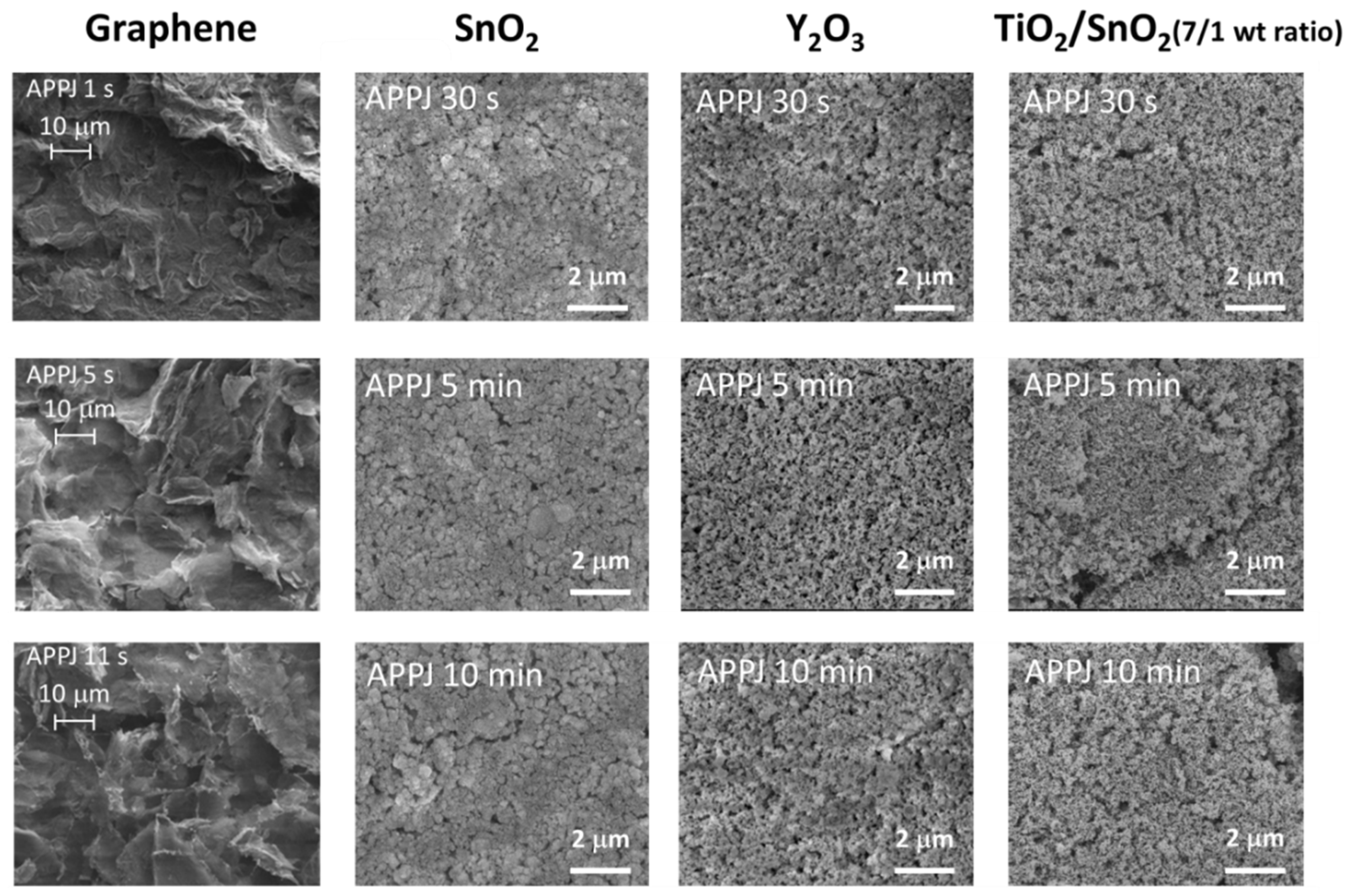
Figure 4.
SEM images of rGOs [
27], nanoporous SnO
2, Y
2O
3, and TiO
2/SnO
2 sintered by APPJs for various durations.
Figure 4.
SEM images of rGOs [
27], nanoporous SnO
2, Y
2O
3, and TiO
2/SnO
2 sintered by APPJs for various durations.
Figure 4 shows SEM images of the nanoporous oxides and 3D rGO nanosheets prepared using the rapid APPJ sintering technique [
27]. The APPJ-sintered 3D rGO nanosheets are porous with some sharp edges revealed. It is worth noted that the optimal APPJ sintering time is merely ~11 s, as indicated by the OES results shown in
Figure 3b-2. A longer sintering process will severely damage rGOs and a nearly complete removal of rGOs was observed with an APPJ sintering of 2 min [
27].
Figure 4 also shows the SEM images of APPJ-sintered nanoporous SnO
2, Y
2O
3, and TiO
2/SnO
2 composites. No apparent difference in surface morphologies was observed for nanoporous oxides sintered by APPJs for 30 s, 5 min, and 10 min. However, some residues from organic binders may be detected by the spectra of optical transmittances for the samples sintered by APPJs for an extremely short duration [
26]. This also indicates that the major effect of the APPJ-sintering processes is the oxidation and removal of organic binders.
Sintering particles involve evaporation-condensation, surface diffusion, volume diffusion, grain-boundary diffusion, and plastic flow processes. The driving force of sintering is associated directly with the curvature at the inter-particle necks. Surface diffusion is the comparatively dominant process for low-temperature sintering [
32]. The typical APPJ temperature is ~250‒700 °C with the APPJ apparatus used in our lab. The temperature can be slightly modulated via the gas flow rate, on/off duty cycle, applied voltage, and ambient gas quenching. This APPJ temperature is considered low from the viewpoint of typical oxide sintering processes. However, according to the Gibbs-Thomson equation, the melting points of particulate materials decreases with the particle sizes [
33,
34,
35]; this is called melting point depression. A lower melting point usually indicates higher atomic diffusion capability at the same sintering temperature. This facilitates nanoparticles sintering at relatively low temperature. In addition, the high curvature surfaces of smaller particles include more surface defective sites such as ledges, kinks, vacancies, and adatoms, resulting in more vigorous surface diffusion activity during the sintering process. When the vibration amplitude of the atoms reaches a critical fraction (~10%) of the nearest-neighbor distance, the solid begins to melt. The melting point of a surface is lower than that of a bulk because surface atoms have fewer bonds and reduced cohesive energy [
36]. Owing to the large surface/volume ratio of nanoparticles, much more significant surface activity is expected for nanoparticles. Therefore, the sintering of nano-sized particles can be performed at a relatively lower temperature.
The other factor favoring the APPJ-sintering processes of nanoparticles is the increasing contact area per unit volume as the particle size decreases. The surface area is proportional to r2 (r: particle radius) and the volume is proportional to r3, rendering the scaling law of 1/r for contact-area/volume ratio. The inter-particle contact area increases dramatically as the radius decreases. When sintering occurs at the contacts of nanoparticles, the large sintered contact area provides strong bonding between particles. This favors the mechanical strength of APPJ-sintered metal oxide nanoparticles. Slight atomic transport may already be sufficient to bond the nanoparticles, offering the required bonding strength for the APPJ-sintered nanoporous materials.
3. Application of APPJs to Energy Harvesting and Storage Devices
APPJ-sintered 3D rGO nanosheets have been successfully implemented as the counter electrodes of DSSCs; energy conversion efficiency comparable to that with Pt counter electrode was obtained [
27].
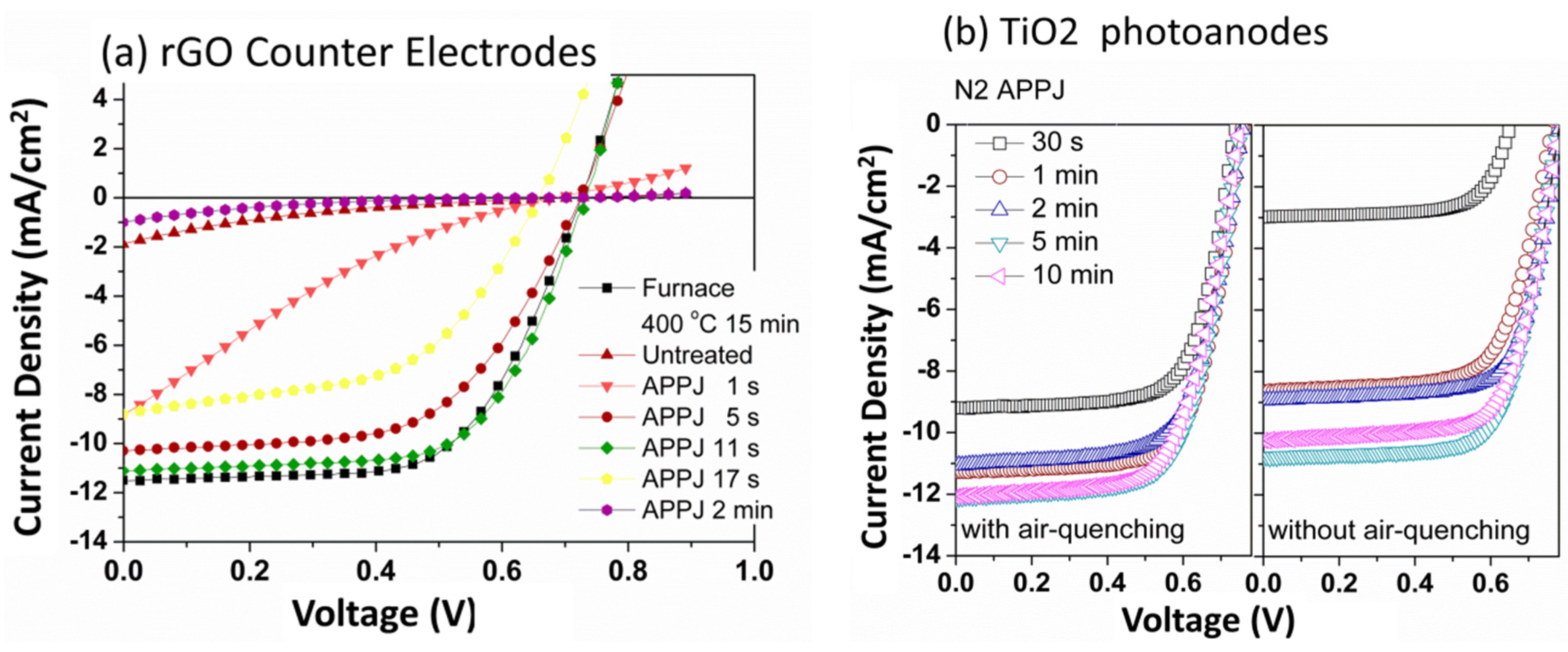
Figure 5a shows the IV curves under the irradiation of a solar simulator. The solar cell performance (energy efficiency) improved with the sintering time. As the sintering time reached 11 s, the solar cell performance becomes comparable to that with rGO counter electrode calcined by a conventional furnace at a 400 °C for 15 min. Further increasing the APPJ-sintering time deteriorated the solar cell performance. As the APPJ-sintering time reached 2 min, the cell completely malfunctioned and most of the rGOs had been burned out. This also indicates the vigorous interaction between N
2 APPJ and carbon-based materials. When a conventional furnace was used, the required calcination time for rGO pastes was 15 min which was much longer than that by APPJ processing. The estimated energy consumption is lower than one-third that of the conventional furnace-calcination process. This APPJ-rGO sintering is therefore a time- and energy-saving process that can reduce the thermal budget and energy payback time when used for solar cell production [
27].
Figure 5b shows the comparison of IV curves of DSSCs with nanoporous TiO
2 photoanodes sintered by N
2 APPJs with and without air-quenching. The ultra-short sintering time exhibits the effectiveness of N
2 APPJ sintering on oxide nanoparticles with organic binders. It can be clearly observed that the sintering of TiO
2 can be accomplished in a shorter duration when air-quenching is applied. Under the same APPJ processing time, the DSSC efficiency is higher when air-quenching is introduced during the APPJ operation. In our previous studies, we also have demonstrated the feasibility of APPJ-sintered nanoporous TiO
2 with the photoanodes of DSSCs that showed efficiency comparable to those made by conventional furnace-calcination processes (510 °C for 15 min) [
24,
25,
26]. Without air-quenching, the required sintering time was ~1 min at an APPJ-sintering temperature of ~500 °C [
26]. By introducing air-quenching, the sintering time was further reduced to 30 s because of the involvement of oxidant (ambient O
2) in the reaction, although the N
2 APPJ-sintering temperature was decreased to ~300 °C. A similar effect was observed when air APPJ was used instead of N
2 APPJ with air-quenching [
24]. O
2 APPJ was also tested, but a strong reaction occurred between the plasmas and the stainless steel jet, resulting in severe corrosion on the jet [
24]. Using a precursor solution injection from the side hole of the quartz tube, APPJs were used to deposit particulate TiO
2 as the scattering layer and simultaneously sinter the screen-printed TiO
2 pastes underneath [
25].
Figure 5.
DSSCs with (
a) rGO counter electrodes [
27] and (
b) nanoporous TiO
2 photoanodes sintered by APPJs for various durations.
Figure 5.
DSSCs with (
a) rGO counter electrodes [
27] and (
b) nanoporous TiO
2 photoanodes sintered by APPJs for various durations.
The significant reactive interaction between APPJs and rGO pastes suggests applicability to the rapid processing of carbon-based materials. We then applied N
2 APPJs to perform surface activation and modification on the graphite felt electrodes of all-vanadium redox flow batteries [
10]. In flow batteries, the electrochemical reaction of vanadium ions occurs on the fiber surfaces of the graphite felts; as a result, it is of great importance to improve the contact between the electrolyte and the graphite fibers as well as to activate the graphite fiber surfaces. This activation process is typically conducted via acid treatment or thermal oxidation that requires hours of operation and/or corrosive chemicals [
37,
38].
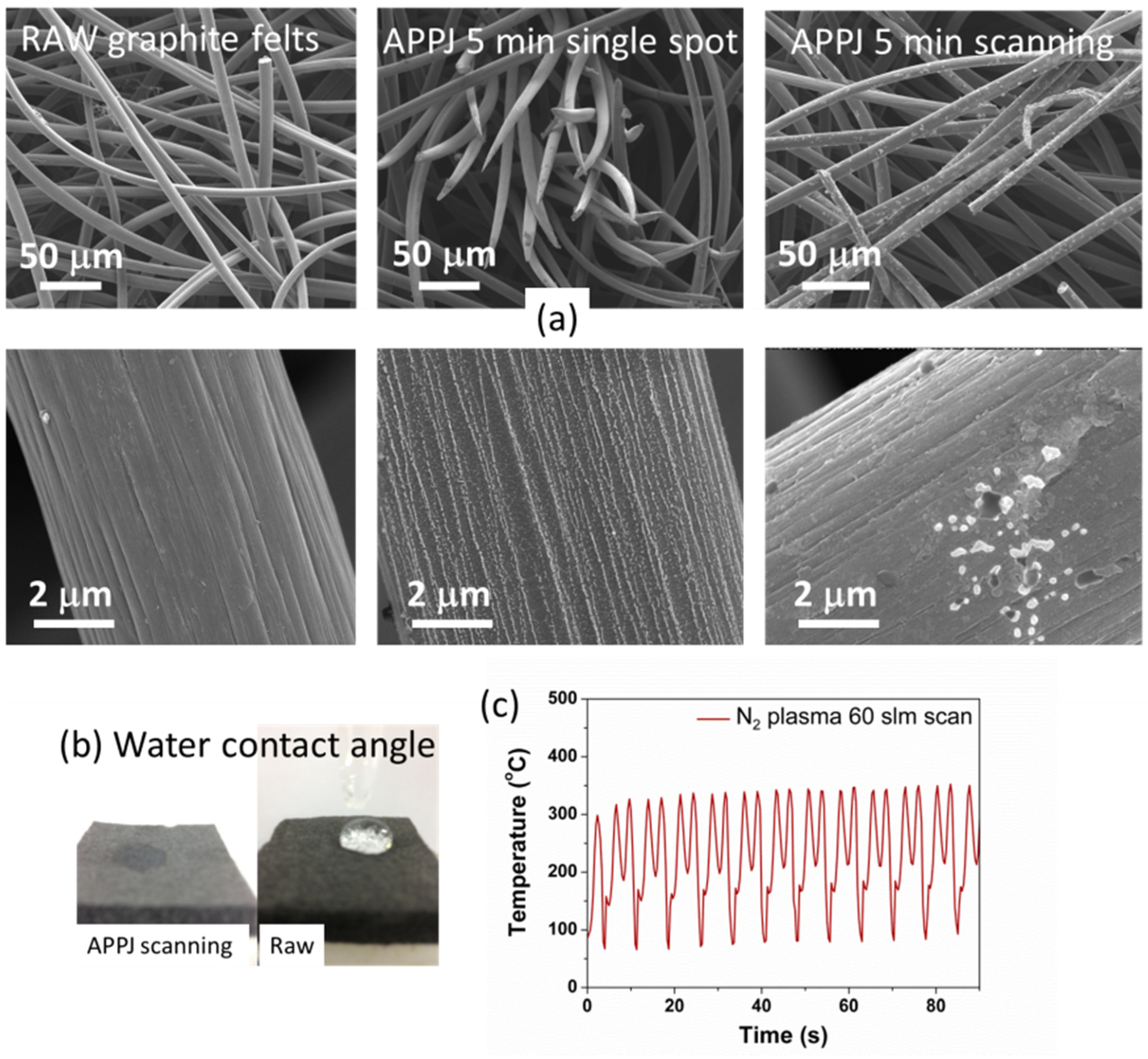
The porosity of graphite felt is usually >90% and the spacing between fibers is ~50 μm, as shown in the SEM images in the left column of
Figure 6a. When treated with APPJs, the jet flows may facilitate the penetration of highly reactive plasma species into the graphite felt, resulting in more complete surface modification throughout the whole graphite felt. This is the advantage of APPJs compared with low-pressure plasma treatment, in which the long mean free path of plasma species may hinder the plasma treatment on the inner parts of the graphite felt. The SEM images in the middle column of
Figure 6a show the morphology of APPJ-treated graphite felts using a single spot mode (the jet position is stationary during APPJ processing). Some graphite fibers were burned out after the APPJ treatment, and some small white spots can be clearly identified. The SEM images in the right column show the APPJ-treated graphite felts in the scanning modes. The scanning mode operation is essential for processing large-area graphite felts. When operated at scanning mode, the temperature oscillates with time (
Figure 6c) because the substrate is cyclically heated up and cooled down during the transportation of graphite felt under the APPJ. This rapidly repeated thermal cycle may cause thermal stresses, resulting in comparatively large surface damage, compared with those on graphite felt treated by APPJs with single spot mode. Flow batteries with graphite felt electrodes treated by APPJs (either single spot or scanning mode) improved the energy efficiency significantly. The APPJ treatment also significantly improved the hydrophilicity (
Figure 6b); the better contact between the electrolyte and the graphite felt fibers and better penetration of electrolyte into the graphite felt led to improved cell performance. Oxygen and nitrogen doping on graphite fiber surfaces was also observed through an XPS experiment. These doping may improve the electrochemical activity as well [
10].
Figure 6.
Graphite felts treated by APPJs. (a) SEM images; (b) water contact angles; and (c) substrate temperature evolution under APPJ scanning mode.
Figure 6.
Graphite felts treated by APPJs. (a) SEM images; (b) water contact angles; and (c) substrate temperature evolution under APPJ scanning mode.


 ,
, 