Article

Phase Evolution and Diffusion Behavior of PM-HIP-Processed Ni-Mo Bimetallic Cladding
1
CISRI HIPEX Technology Co., Ltd., Beijing 100081, China
2
National Key Laboratory of Metallurgical Intelligent Manufacturing System, China Iron & Steel Research Institute Group Co., Ltd., Beijing 100081, China
*
Author to whom correspondence should be addressed.
Coatings 2026, 16(9), 1008; https://doi.org/10.3390/coatings16091008
Submission received: 10 July 2026 / Revised: 5 August 2026 / Accepted: 14 August 2026 / Published: 24 August 2026
(This article belongs to the Section High-Energy Beam Surface Engineering and Coatings)

Abstract

Ni–Mo alloy claddings were fabricated on low-carbon steel substrates using powder metallurgy combined with hot isostatic pressing (PM-HIP). The interfacial microstructure, elemental interdiffusion, phase composition and microhardness distribution of the bimetallic composite were investigated systematically. The results show that sound metallurgical bonding without pores, cracks and element dilution is achieved under the HIP process of 1100 °C, 120 MPa and 4 h holding time. Interdiffusion of Fe, Ni and Mo atoms forms a 20–50 μm thick interfacial transition layer, and Mo exhibits a relatively low diffusion capacity due to its large atomic radius. Two intermetallic phases, Ni4Mo and NiMo, are formed in the cladding layer because of the inhomogeneous distribution of Mo. A prominent microhardness gradient is observed throughout the composite, and the interfacial layer presents the highest hardness of 905 HV resulting from multiple strengthening mechanisms. As an effective alternative to traditional welding and cladding technologies, the PM-HIP process exhibits great potential for manufacturing complex bimetallic components with prospective service prospects in severe corrosive environments.

1. Introduction

In the chemical and energy sectors, the selection of materials capable of withstanding extreme corrosive environments is paramount for both operational safety and economic feasibility [1]. Hydrochloric acid, as a strong reducing acid, poses a severe challenge to the majority of metallic materials. In hydrochloric acid synthesis reactors, materials are required not only to exhibit corrosion resistance but also to maintain structural integrity at elevated temperatures [2,3,4]. Ni-Mo alloys have emerged as the preferred choice for such applications due to their unique compositional design. Benefiting from their high molybdenum content, Ni-Mo alloys can form stable passive films in reducing acid environments, thereby effectively resisting acid attack [5]. Furthermore, in the context of deep-sea oil and gas exploitation—particularly in high-temperature and high-pressure fields containing H2S and CO2—materials are highly susceptible to severe sulfide stress corrosion cracking. Conventional carbon steels fail rapidly under these conditions, necessitating the use of corrosion-resistant alloys [6].
In order to combine the outstanding corrosion resistance of Ni–Mo alloys with the mechanical strength and low cost of carbon steel, a variety of techniques have been developed over recent decades for fabricating bimetallic cladding layers or liners. Overlay welding, including gas tungsten arc welding and plasma transferred arc welding, has been widely adopted to deposit Ni-based corrosion-resistant layers on steel substrates; however, the dilution of alloying elements by Fe from the substrate inevitably degrades the corrosion resistance of the cladding layer [7]. Explosive welding represents another commercially important route capable of joining large-area plates. Nevertheless, Parchuri et al. [8] observed that when preparing Mo/Cu composite plates by explosive welding, microcracks and voids appeared around grain boundaries near the interface as a result of impact shock. Such shock-wave damage is highly sensitive to process parameters including horizontal collision velocity and collision angle, which directly determine the final weld quality. Roll bonding has also been explored for producing layered composite plates, yet its application is largely restricted to simple geometries and flat products. With respect to advanced surface technologies such as laser cladding and thermal spraying, Sun et al. [9] attempted to deposit a Mo/Ni layer on a copper substrate by laser cladding. Due to the combined effects of poor fluidity of the molybdenum melt pool and non-equilibrium solidification under laser conditions, a considerable number of pores and cracks were formed in the pure Mo layer. Dehm et al. [10] first coated copper powders with nickel-based powder and subsequently prepared a Ni–B–Si plasma-sprayed coating on the copper substrate. Although this coating improved surface hardness, significant thermal stress generated during cooling caused the fracture of a large amount of borides; meanwhile, the rapid cooling rate inherent to laser processing also facilitates the initiation of cracks on the cladding surface. Li et al. [11] deposited Ni60PTA alloy powder on a 45 steel substrate using laser cladding and found that the microstructure of the cladding layer varied considerably in different regions: equiaxed crystals formed at the top surface due to rapid cooling, cellular crystals transformed into cellular dendrites in the middle region where the cooling rate decreased, and a relatively coarse microstructure developed near the bottom owing to the steep temperature gradient. Collectively, these investigations demonstrate that, irrespective of whether fusion welding, explosive joining, or high-energy beam cladding is employed, common drawbacks persist, including dilution of alloying elements, a coarse or non-equilibrium heat-affected zone, high residual stress, and the susceptibility to cracks and porosity [12].
The powder metallurgy approach integrated with hot isostatic pressing has emerged as a solid-state joining technique that can effectively circumvent the intrinsic limitations of the aforementioned conventional methods. During the HIP diffusion bonding process, encapsulated metal powders are simultaneously subjected to elevated temperature and isostatic gas pressure, which promotes powder densification and elemental interdiffusion across the substrate–liner interface, with the entire process being conducted completely in the solid state [13,14,15,16]. This technique offers distinct advantages such as near-net-shape capability, a homogeneous and dense microstructure, extremely low alloy dilution, and the absence of the heat-affected zone typical of fusion welding. It has been demonstrated that a defect-free metallurgical bonding interface can be obtained on steel substrates by this approach [17]. However, the application of the powder-metallurgy-based HIP process to fabricate Ni–Mo alloy liners on carbon steel substrates is still in the exploratory stage, and a systematic understanding of the resulting interfacial microstructure and phase evolution remains insufficiently developed. Therefore, the present study employs a powder metallurgy method utilizing HIP diffusion bonding to fabricate Ni–Mo alloy liners on a carbon steel substrate. The research aims to evaluate the feasibility of this method for producing dense, pore-free Ni–Mo alloy layers, with particular emphasis on characterizing the microstructure of the interface between the alloy layer and the carbon steel substrate, thereby providing a new solution for manufacturing complex bimetallic components.

2. Experimental

2.1. Materials

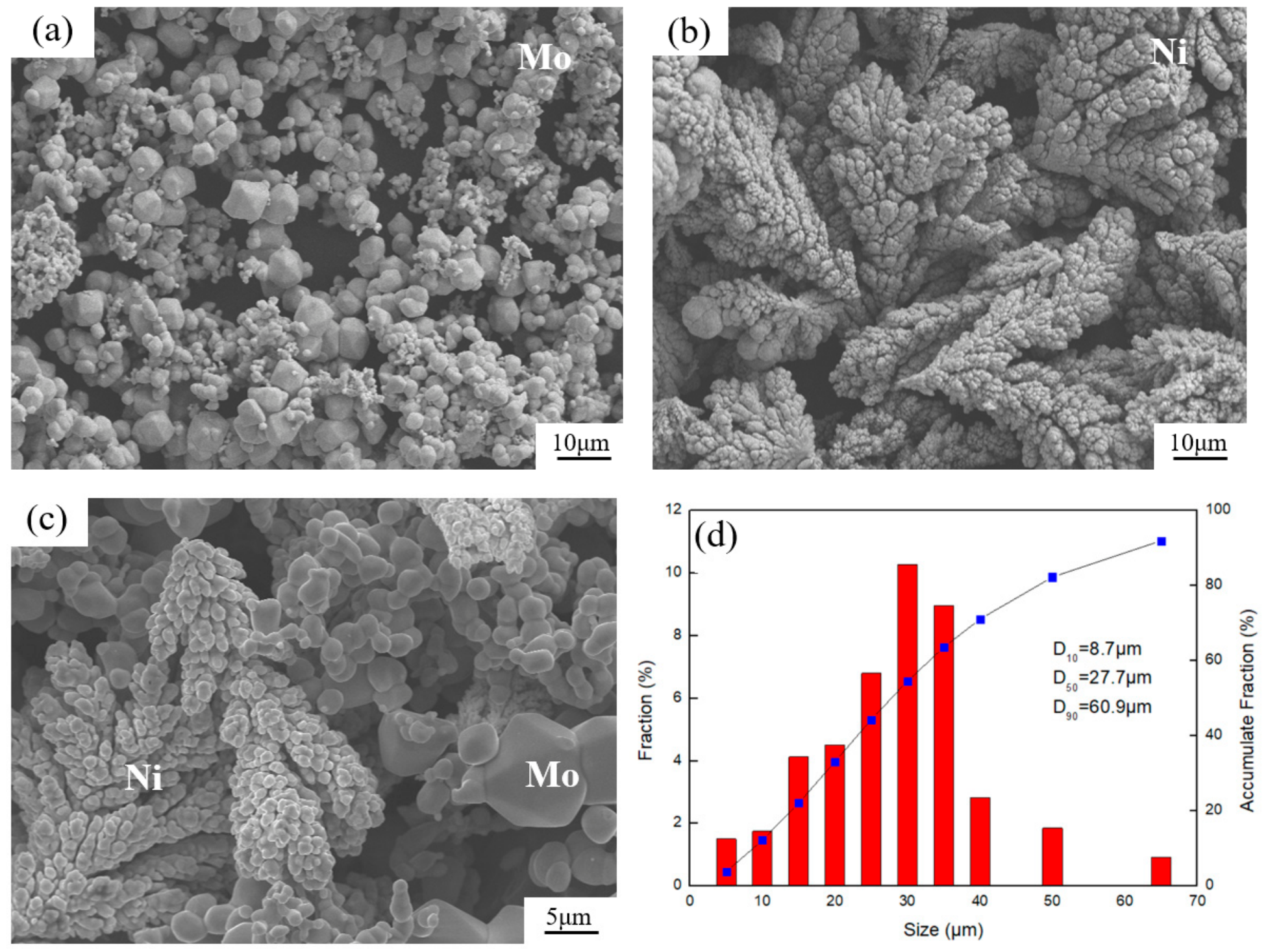
Hydrogen-reduced molybdenum powder and electrolytic nickel powder were used as raw materials for the corrosion-resistant coating. The particle size of both powders was controlled within the range of 5–75 μm to obtain a favorable packing density. The micro-morphologies of Ni and Mo powders are presented in Figure 1. Mo powder prepared by hydrogen reduction exhibits irregular near-spherical particles. This preparation method features low cost and easy mass production. Meanwhile, the desirable packing density of Mo powder facilitates the densification and sintering process of powder compacts. Electrolytic Ni powder consists of dendritic and near-spherical agglomerates with rough surfaces and large specific surface areas. Such morphology improves the sintering activity of the powder, promotes the formation of interfacial solid solutions and elemental interdiffusion, and further accelerates alloy solid solution and diffusion bonding. Nevertheless, the flowability of Ni powder is relatively poor. The two powders were blended for 4 h at a rotational speed of 15 r/min using a three-dimensional mixer under argon shielding. Laser particle size analysis was conducted on the blended powder, and the results are shown in Figure 1d. The measured characteristic particle sizes are as follows: D10 = 8.7 μm, D50 = 27.7 μm, and D90 = 60.9 μm. The powder formulation was targeted to synthesize a Ni-30 at.% Mo solid solution, corresponding to a mass fraction of 40 wt.% Mo and 60 wt.% Ni. The composition selected in this study is a classic and widely validated formula for high-performance corrosion-resistant Ni-Mo alloys [18].

2.2. Experimental Methods

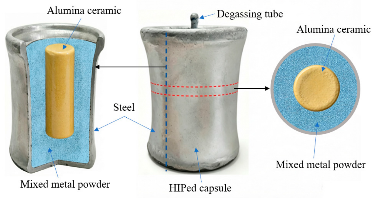
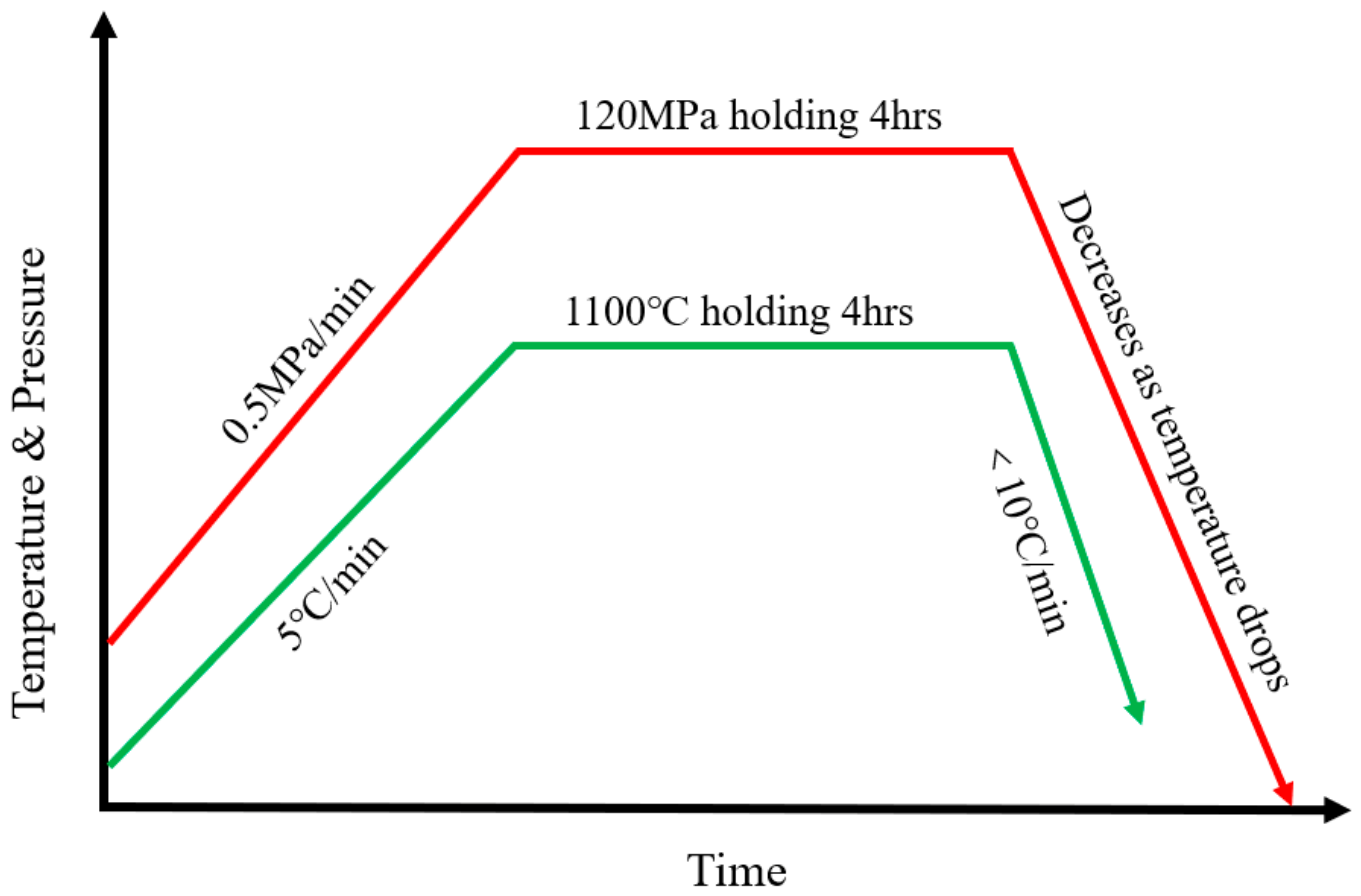
A low-carbon steel capsule (ASTM A36) with an inner diameter of 50 mm, a height of 80 mm, and a wall thickness of 3 mm was fabricated for the HIP experiment. As illustrated in Figure 2, an alumina ceramic rod was coaxially inserted into the center of the steel capsule as a physical barrier to precisely control the geometric shape and dimensional accuracy of the internal cavity. The annular gap between the alumina ceramic rod and the inner wall of the steel capsule was filled with homogeneously mixed Ni and Mo powders with a stoichiometric ratio (Ni-30 at.% Mo). The fully packed steel capsule was subjected to hot isostatic pressing treatment under a high-purity argon atmosphere. The detailed thermal cycle profile of the HIP process is presented in Figure 3. The specimen was heated to 1100 °C at a constant heating rate of 5 °C/min. Meanwhile, the pressure was increased to 120 MPa at a pressurization rate of 0.5 MPa/min. The specimen was held at the optimized temperature and pressure for 4 h to guarantee complete densification of the mixed powders and achieve sufficient interfacial diffusion and metallurgical bonding. To minimize residual thermal stress and avoid structural defects induced by rapid temperature change, the cooling rate was strictly controlled below 10 °C/min throughout the entire process. The core control principle relies on the real-time temperature compensation function of the equipment heating elements. When the natural cooling trend tends to be too fast, the heating body will automatically and dynamically supplement heat to slow down the cooling process. By this closed-loop temperature regulation method, the sample was cooled strictly following the programmed rate, and the overall cooling rate was steadily and reliably maintained below 10 °C/min throughout the entire experiment.

2.3. Microstructure and Property Characterization

Specimens were sectioned perpendicular to the cross-section using a wire-cutting machine. One specimen was taken from both the substrate and the bonding interface, with dimensions of 15 mm × 10 mm × 10 mm. The mounted specimens were ground step-by-step using SiC abrasive papers (SHANGSHA, Shanghai, China) (#120 to #1200), followed by mechanical polishing with diamond suspensions. The final polishing step was performed using 0.5 μm diamond suspension to obtain a scratch-free surface. The steel side was etched with 4% nital for 10 s, while the Ni-Mo layer was etched with an etchant composed of HNO3: HCl: HF = 1:2:2 for 5 s.
The microstructure evolution and elemental diffusion of the specimens were characterized using an optical microscope (OLYMPUS GX53, OLYMPUS, Tokyo, Japan), a scanning electron microscope (Zeiss SUPER 55, Carl Zeiss, Oberkochen, Germany), and an energy dispersive spectroscopy (EDS) analyzer.
The phase composition of the cladding layer was analyzed by an X-ray diffractometer (Bruker D8 ADVANCE, Bruker, Karlsruhe, Germany) with a Co target, operating at a tube current of 40 mA, a tube voltage of 35 kV, a scanning speed of 2°/min, and equipped with a LYNXEYE XE detector (Bruker, Karlsruhe, Germany).
The cross-sectional microhardness of the samples was measured using an FY8PRO-1000A microhardness tester (Jinan Fangyuan, Jinan, China) under an applied load of 0.5 N with a dwell time of 10 s. The hardness measurements were repeated three times along the direction from the steel surface to the cladding substrate. The indentation points were arranged at intervals of 200 μm in the horizontal direction.

3. Results and Discussion

3.1. Microstructure of Cladding Coatings

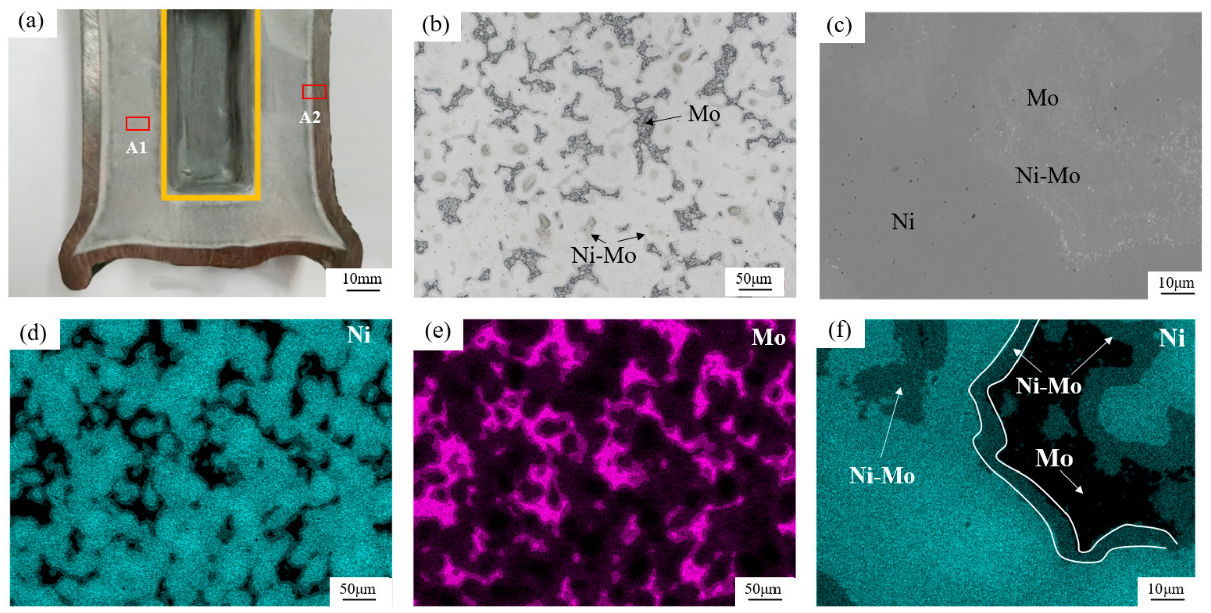
Figure 4a shows the macroscopic cross-sectional morphology of the specimen after hot isostatic pressing and machining. The powder compact undergoes obvious shrinkage, leading to deformation of the outer capsule. Benefiting from the supporting effect of the central ceramic rod, the internal cavity maintains a regular shape. Figure 4b presents the metallographic structure of the dense Ni-Mo alloy matrix, in which molybdenum particles are uniformly distributed. Figure 4c is the scanning electron microscopy (SEM) micrograph of the metallographic specimen, revealing that an interfacial transition phase is formed between Mo particles and the Ni matrix. As indicated by the combined SEM–energy dispersive spectroscopy (SEM-EDS) results (Figure 4d–f), HIP treatment induces elemental interdiffusion between nickel and molybdenum, thereby forming solid solutions. Uniformly dispersed residual Mo particles are observed within the matrix, and distinct interfacial reaction layers are generated at the interface. Further phase identification of the as-fabricated Ni-Mo alloy was performed via X-ray diffraction (XRD).

3.2. Analysis of Phase Compositions in Cladding Coatings

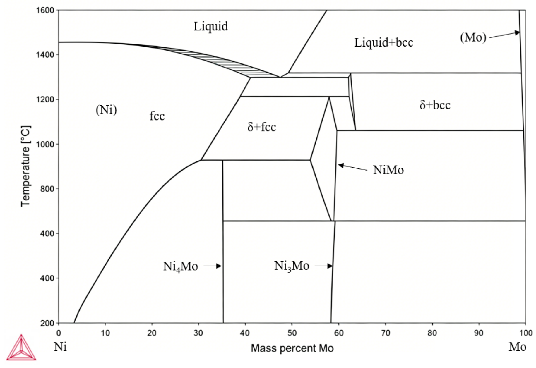
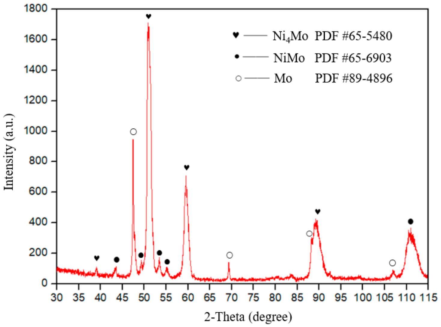
Figure 5 presents the Ni-Mo binary phase diagram computed by the thermodynamic software Thermo-Calc (v2023a). It reveals that the Ni-rich alloy with 30 at.% Mo (40 wt.% Mo) contains three ordered intermetallics: Ni4Mo, Ni3Mo and NiMo. Previous works have thoroughly explored the phase formation process of Ni-Mo alloys, establishing that upon solution treatment at 900–1250 °C, the 30 at.% Mo alloy typically forms a short-range ordered (SRO) fcc α solid solution. This disordered solid solution is metastable and tends to decompose into the equilibrium long-range ordered (LRO) Ni4Mo phase upon cooling below 900 °C [19,20,21]. However, the HIP process was performed at 1100 °C, a temperature where the single-phase α-solid solution is thermodynamically stable. At this elevated temperature, Mo solubility in the fcc lattice is maximized, and the lattice parameter varies linearly with Mo content according to Vegard’s law. Despite the high temperature favoring a homogeneous solid solution, the slow cooling inherent to the post-HIP cycle likely suppressed the complete disordering or the formation of equilibrium phases predicted at room temperature. As shown in Figure 6, diffraction peaks confirm the presence of two distinct intermetallic phases: Ni4Mo and NiMo. The coexistence of these phases is attributed to the incomplete homogenization of Mo across the diffusion couples. The microstructure evolution is governed by local stoichiometry and diffusion kinetics: regions derived from original Mo particles act as diffusion sources, creating local Mo-rich environments that first attain the stoichiometry required for the NiMo phase (1:1), thereby nucleating its specific lattice [21]. Conversely, in the Mo-lean regions (the original Ni matrix side), the local concentration is insufficient to form NiMo; instead, these areas reach the stoichiometric ratio of Ni4Mo (4:1 ratio) and generate the corresponding lattices. This indicates that while HIP promotes densification, the diffusion distance of Mo atoms was insufficient to fully homogenize the 60 wt.% Mo content, resulting in a chemically graded microstructure containing coexisting intermetallics.

3.3. Microstructure Analysis near the Bonding Interface

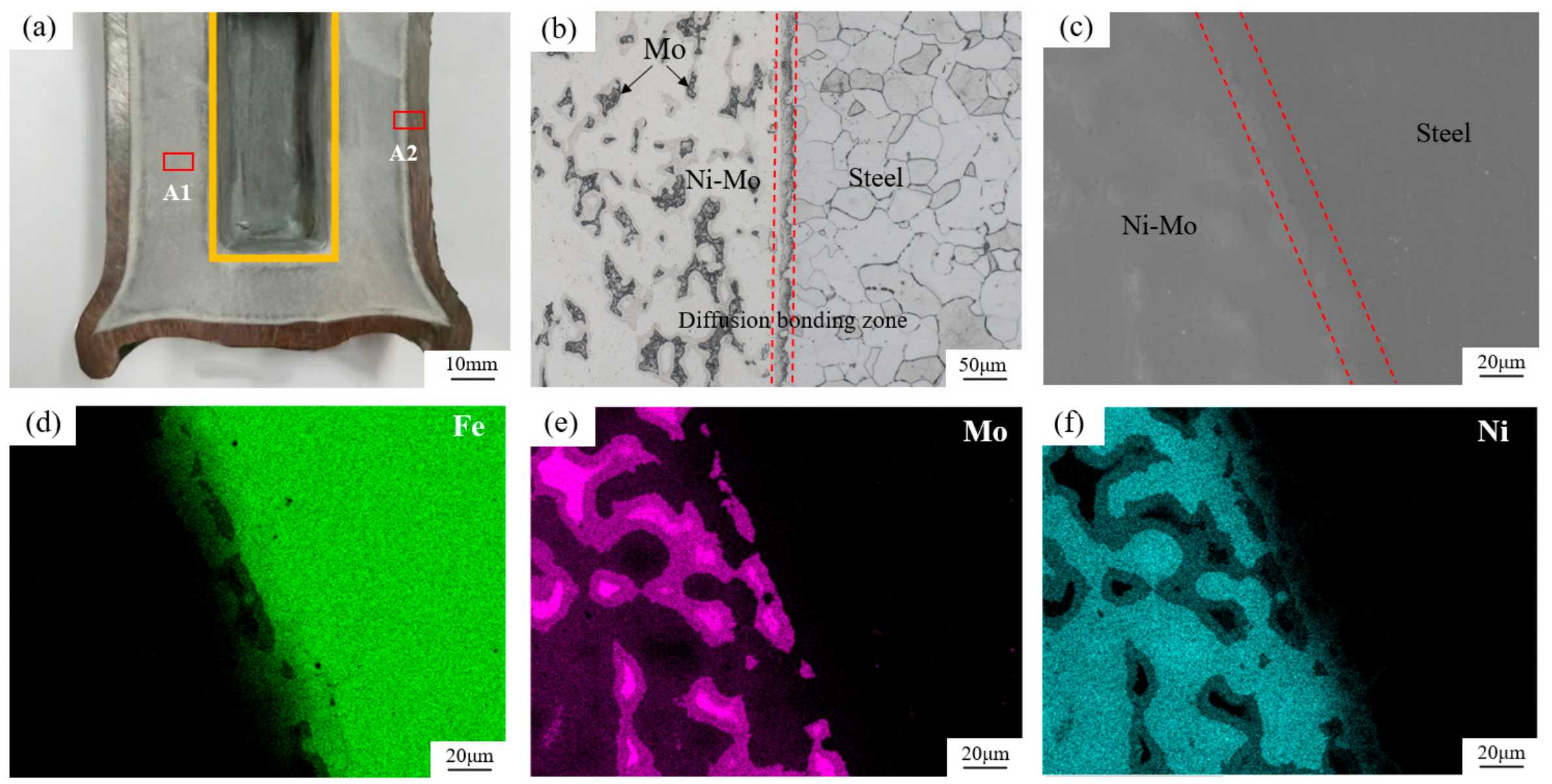
Region A2 in Figure 7a shows the macroscopic morphology of the diffusion bonding interface between the Ni-Mo matrix and steel substrate after hot isostatic pressing treatment. Integral bonding and continuous interfacial characteristics can be observed between the two substrates without macroscopic delamination or separation. Figure 7b displays the metallographic microstructure of the diffusion interface. It is verified that the bonding zone is compact and defect-free, with no visible pores or microcracks. The scanning electron microscopy micrograph in Figure 7c reveals a uniform and continuous interfacial transition zone formed between the steel substrate and Ni-Mo alloy matrix. Combined with the SEM-EDS elemental analysis results (Figure 7d–f), the high-temperature and high-pressure coupling effect during HIP treatment induces the interdiffusion of Ni and Mo from the alloy matrix and Fe from the steel substrate across the interface.

3.4. Element Interdiffusion Analysis near the Bonding Interface

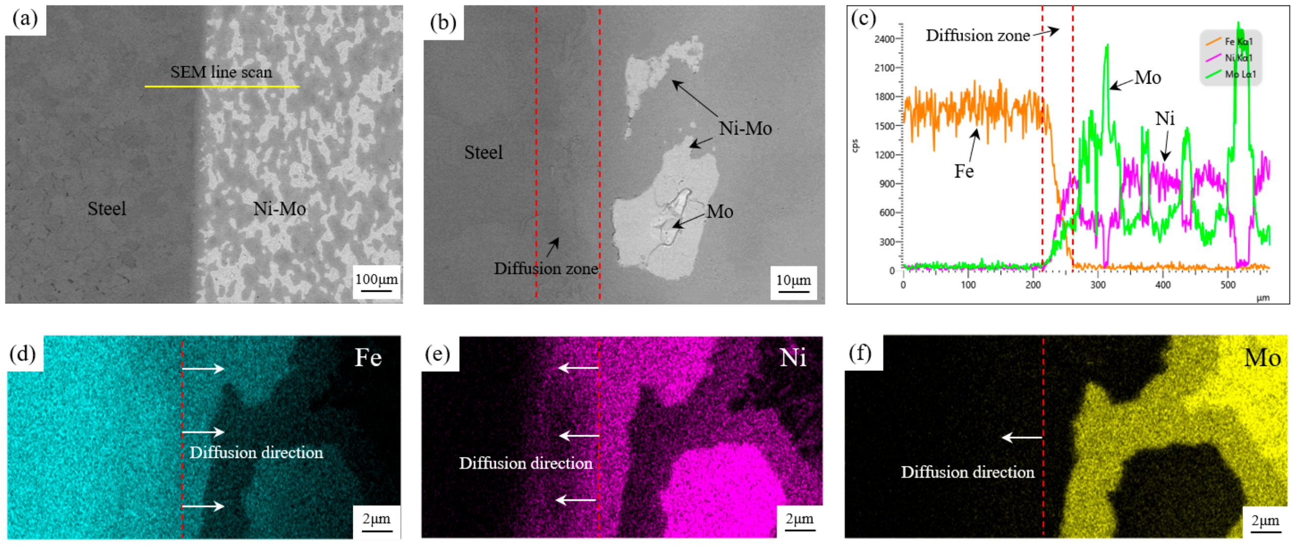
The diffusion bonding interface between the Ni-Mo alloy layer and carbon steel is displayed in Figure 8a,b. Figure 8a (low magnification) covers a wide observation area, and Figure 8b (high magnification) focuses on microscopic defects. Notably, no microcracks or pores are found at the interface. This defect-free morphology is attributed to the synergistic effect of high temperature and isostatic pressure during the HIP process, which promotes the plastic deformation of asperities and accelerates the creep closure of voids. SEM-EDS line scanning across the interface (Figure 8c) verifies the interdiffusion of Fe, Ni, and Mo, confirming the transition from mechanical contact to metallurgical bonding. As shown in elemental mapping (Figure 8d–f), Fe and Ni diffuse intensely across the interface, forming a broad concentration gradient. In contrast, Mo exhibits a steeper concentration gradient with limited diffusion depth. The diffusion rate of atoms in a solid matrix is essentially governed by diffusion activation energy. A higher activation energy creates a larger energy barrier for atomic jumps, leading to a smaller diffusion coefficient. Molybdenum exhibits a low diffusion rate in the Fe–Ni matrix owing to its high diffusion activation energy. As calculated in Ref. [22], the diffusion activation energy of Mo in the Fe–Ni matrix reaches 360 kJ/mol. This phenomenon arises from the considerably larger atomic size of Mo relative to matrix atoms, which induces severe lattice distortion during atomic migration. Meanwhile, strong interatomic bonding between Mo and Fe/Ni further raises the energy required for atoms to escape from their equilibrium sites. In contrast, Fe diffuses faster in the Ni matrix with a remarkably lower activation energy. Ref. [23] reports that the diffusion activation energy of Fe in the Ni matrix ranges from 192 to 241 kJ/mol. Fe and Ni possess similar atomic sizes and adopt the face-centered cubic (FCC) crystal structure, which guarantees favorable atomic compatibility. More importantly, the energy barrier for the exchange between Fe atoms and vacancies is lower than that for Ni, and Fe atoms can spontaneously relax toward adjacent vacancies, substantially reducing migration resistance. Consequently, the fundamental difference between the two diffusion behaviors originates from diffusion activation energy as the core parameter. This parameter comprehensively characterizes how atomic migration barriers are modulated by atomic size, interatomic bonding strength and atom–vacancy interactions.

3.5. Microhardness

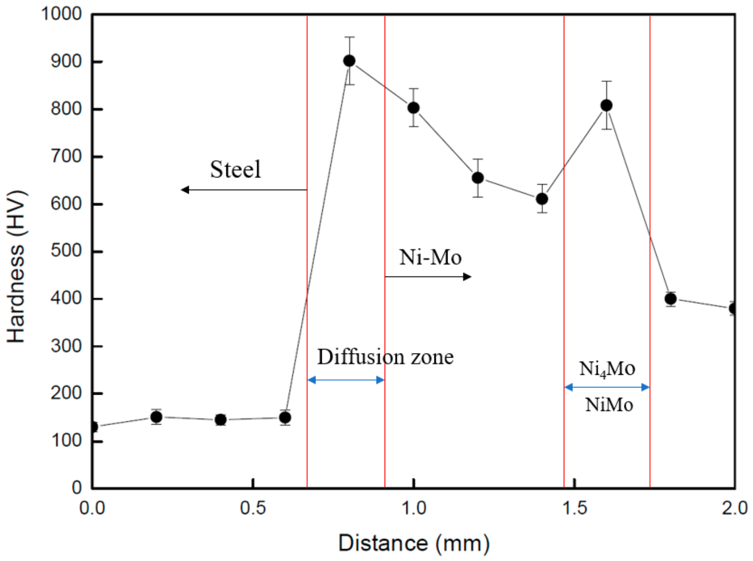
Figure 9 presents the cross-sectional hardness distribution from the steel substrate to the Ni-Mo cladding layer along the direction perpendicular to the bonding interface. The results show that the surface hardness of the steel matrix is relatively low, ranging from 120 to 150 HV, which corresponds to the intrinsic hardness characteristics of low-carbon steel. As the test position approaches the bonding interface, the hardness value increases sharply, with a maximum hardness of 905 HV detected at the interfacial region, indicating an obvious interfacial hardening behavior. The hardness of the Ni-Mo alloy matrix ranges from 350 to 650 HV. Notably, a local hardness peak of 810 HV appears within the Ni-Mo layer, which is attributed to the in-situ formation of hard intermetallic phases such as Ni4Mo and NiMo during the hot isostatic pressing process. These hard phases are generated by sufficient interdiffusion and solid-phase reaction between Ni and Mo elements, thereby producing a prominent second-phase strengthening effect.
In accordance with the evaluation criteria for metallurgical bonding of diffusion bonding, effective cross-interface elemental interdiffusion is a critical indicator of qualified metallurgical bonding [24,25,26,27]. Different from mechanical bonding with abrupt interfacial performance changes, the continuous and gradient hardness transition from the steel substrate to the Ni-Mo cladding layer, combined with the confirmed cross-interface interdiffusion of Fe, Ni and Mo elements, fully verifies that atomic-level metallurgical bonding is successfully achieved between the steel substrate and Ni-Mo alloy layer, which meets the standard of diffusion metallurgical bonding for dissimilar metals. Furthermore, the Ni-Mo-Fe interfacial mixed layer exhibits a higher hardness than both the single Ni-Mo alloy layer and the individual hard phase enrichment region. This superior hardness performance stems from the synergistic effect of multiple strengthening mechanisms. The interdiffusion of Fe from the steel substrate with Ni and Mo elements promotes the formation of multi-element solid solutions and induces solid solution strengthening. Meanwhile, the refined interfacial microstructure provides grain refinement strengthening, which is further coupled with the second-phase strengthening of hard intermetallic compounds. The combined effect of these multiple strengthening mechanisms ultimately endows the interfacial mixed transition layer with the optimal microhardness.

4. Conclusions

Defect-free Ni–Mo alloy claddings were successfully prepared on carbon steel substrates by PM-HIP solid-state diffusion bonding, and the core conclusions are summarized as follows:
  • Optimized HIP treatment achieves pore- and crack-free metallurgical bonding between Ni–Mo alloy and carbon steel, eliminating element dilution, high residual stress and heat-affected zone defects of traditional welding, explosive welding and laser cladding. A 20–50 μm thick transition layer forms via interdiffusion of Fe, Ni and Mo; Mo presents limited diffusion depth due to its larger diffusion activation energy.
  • Interdiffusion of Ni and Mo generates dual intermetallic phases Ni4Mo and NiMo in the cladding layer, caused by incomplete Mo homogenization. A distinct hardness gradient exists across the composite: the steel substrate is 120–150 HV, the Ni–Mo matrix 350–650 HV, and the multi-element interface reaches a peak hardness of 905 HV owing to combined solid-solution, grain refinement and second-phase strengthening.
  • The PM-HIP technique serves as a reliable alternative to conventional composite manufacturing methods and enables the fabrication of complex-structured bimetallic components. Benefiting from the well-recognized excellent corrosion resistance of Ni–Mo alloys, the prepared PM-HIP bimetallic composites possess promising application potential in harsh corrosive environments, such as hydrochloric acid reactors and deep-sea oil-gas service equipment. Future investigations will focus on optimizing capsule designs for complex geometries and larger component dimensions, as well as systematically evaluating the mechanical and corrosion resistance properties of the fabricated bimetallic joints.

Author Contributions

Conceptualization, Z.W. and P.T.; methodology, Z.W.; validation, P.T., G.L. and X.L.; investigation, Z.W.; writing—original draft preparation, Z.W.; writing—review and editing, P.T.; supervision, X.L.; funding acquisition, G.L. All authors have read and agreed to the published version of the manuscript.

Funding

This research received no external funding.

Institutional Review Board Statement

Not applicable.

Informed Consent Statement

Not applicable.

Data Availability Statement

The raw data supporting the conclusions of this article will be made available by the authors on request.

Conflicts of Interest

Authors Zhanfang Wu, Peixin Tang, Guirong Liu and Xiangyang Li were employed by the company CISRI HIPEX Technology Co., Ltd. Author Xiangyang Liwas employed by the company China Iron & Steel Research Institute Group Co., Ltd.

References

  1. Bender, R.; Féron, D.; Ritter, S. Corrosion challenges towards a sustainable society. Mater. Corros. 2022, 73, 1730–1751. [Google Scholar] [CrossRef] [Scilit]
  2. Zhao, H.; Xie, L.; Xin, C.; Li, N.; Zhao, B.; Li, L. Effect of molybdenum content on corrosion resistance and corrosion behavior of Ti-Mo titanium alloy in hydrochloric acid. Mater. Today Commun. 2023, 34, 105032. [Google Scholar] [CrossRef] [Scilit]
  3. Hou, D.; Luo, H.; Pan, Z.; Zhao, Q.; Cheng, H.; Wang, X. Effect of Cr on the microstructure and corrosion behavior of nickel-based alloys in hydrochloric acid. J. Mater. Res. Technol. 2024, 32, 2867–2881. [Google Scholar] [CrossRef] [Scilit]
  4. Tsau, C.-H.; Chen, P.-M. Corrosion Behavior of Cr19Fe22Co21Ni25Mo13 Alloy in 1M Nitric Acid and 1M Hydrochloric Acid Solutions. Crystals 2021, 11, 1289. [Google Scholar] [CrossRef] [Scilit]
  5. Liu, J.-H.; Li, W.-H.; Pei, Z.-L.; Gong, J.; Sun, C. Investigations on the structure and properties of nanocrystalline Ni-Mo alloy coatings. Mater. Charact. 2020, 167, 110532. [Google Scholar] [CrossRef] [Scilit]
  6. Pinoski, L.; Antony, J.-S.; Menezes, P.-L. Stress corrosion cracking: Mechanisms, materials challenges, and engineering solutions. Materials 2026, 19, 898. [Google Scholar] [CrossRef] [Scilit] [PubMed]
  7. Suthar, F.-V.; Shah, H.-N.; Mandal, D.; Chaudhury, S.-K. Effect of alloy 625 buffer layer on corrosion resistance of nickel base hardfacing. Surf. Coat. Technol. 2024, 483, 130893. [Google Scholar]
  8. Parchuri, P.-K.; Kotegawa, S.; Ito, K.; Yamamoto, H.; Mori, A.; Tanaka, S.; Hokamoto, K. Characterization of shock wave damages in explosion welded Mo/Cu clads. Metals 2021, 11, 501. [Google Scholar] [CrossRef] [Scilit]
  9. Sun, M.; Pang, M. Defect Formation Mechanism and Performance Study of Laser Cladding Ni/Mo Composite Coating. Coatings 2021, 11, 1460. [Google Scholar] [CrossRef] [Scilit]
  10. Dehm, G.; Medres, B.; Shepeleva, L.; Bamberger, M.; Mordike, B.-L.; Mordike, S.; Ryk, G.; Halperin, G.; Etsion, I. Microstructure and tribological properties of Ni-based claddings on Cu substrates. Wear 1999, 225–229, 18–26. [Google Scholar] [CrossRef] [Scilit]
  11. Li, T.; Long, H.; Qiu, C.; Wang, M.; Li, D.; Dong, Z.; Gui, Y. Multi-Objective Optimization of Process Parameters of 45 Steel Laser Cladding Ni60PTA Alloy Powder. Coatings 2022, 12, 939. [Google Scholar] [CrossRef] [Scilit]
  12. Mendes, R.; Ribeiro, J.-B.; Loureiro, A. Effect of explosive characteristics on the explosive welding of stainless steel to carbon steel in cylindrical configuration. Mater. Des. 2013, 51, 182–192. [Google Scholar] [CrossRef] [Scilit]
  13. Huang, S.; Shen, C.; Samarov, V. Processing, microstructure, and properties of bimetallic steel-Ni alloy powder HIP. Metals 2024, 14, 118. [Google Scholar] [CrossRef] [Scilit]
  14. Lin, A.; Lee, J.; Lou, X.; Zhang, Y. Phase-field modeling of interdiffusion between dissimilar Fe-Cr-Ni alloys during non-isothermal hot isostatic pressing. Comput. Mater. Sci. 2025, 246, 113357. [Google Scholar] [CrossRef] [Scilit]
  15. Grehk, M. Microstructure and fatigue behavior of PM-HIPed Ni-based superalloys and martensitic tool steels: A review. Metals 2024, 14, 1159. [Google Scholar] [CrossRef] [Scilit]
  16. Le, J.; Yang, J.; Yin, H.; Samarov, V.; Gandy, D.; Lou, X. SA508 low alloy steel to 316L stainless steel dissimilar metal joint made by powder metallurgy hot isostatic pressing. Mater. Sci. Eng. A 2023, 875, 145060. [Google Scholar] [CrossRef] [Scilit]
  17. Sergi, A.; Khan, R.-H.; Careri, F.; Hamilton, H.; Meisnar, M.; Makaya, A.; Attallah, M.-M. Diffusion bonding of dissimilar materials for space applications via hot isostatic pressing. Mater. Lett. 2024, 376, 137260. [Google Scholar] [CrossRef] [Scilit]
  18. Chen, M.-F.; Douglass, D.-L. The effect of Mo on the high-temperature sulfidation of Ni. Oxid. Met. 1989, 32, 185–206. [Google Scholar] [CrossRef] [Scilit]
  19. Schalenbach, M.; Speck, F.-D.; Ledendecker, M.; Kasian, O.; Goehl, D.; Mingers, A.-M.; Mayrhofer, K.-J. Nickel-molybdenum alloy catalysts for the hydrogen evolution reaction: Activity and stability revised. Electrochim. Acta 2018, 259, 1154–1161. [Google Scholar] [CrossRef] [Scilit]
  20. Zhou, S.-H.; Wang, Y.; Jiang, C.; Zhu, J.-Z.; Chen, L.-Q.; Liu, Z.-K. First-principles calculations and thermodynamic modeling of the Ni–Mo system. Mat. Sci. Eng. A-Struct. 2005, 397, 288–296. [Google Scholar] [CrossRef] [Scilit]
  21. Ustinovshikov, Y.; Shabanova, I. Phase transitions in alloys of the Ni–Mo system. Mater. Chem. Phys. 2011, 129, 975–980. [Google Scholar] [CrossRef] [Scilit]
  22. Watson, H.-C.; Watson, E.-B. Siderophile trace element diffusion in Fe–Ni alloys. Phys. Earth Planet. Inter. 2003, 139, 65–75. [Google Scholar] [CrossRef] [Scilit]
  23. Fu, T.; Liu, Y.; Liu, H.; Du, C.; Wen, S.; Du, Y. Interdiffusivity matrices and atomic mobilities in fcc Ni–Fe–Mo alloys: Experiment and modeling. Calphad 2024, 87, 102773. [Google Scholar] [CrossRef] [Scilit]
  24. Sun, H.; Han, Y.; Li, Y. Microstructure and strength of diffusion bonding W alloy/304 stainless steel joint using a Cu interlayer. Int. J. Refract. Met. Hard Mater. 2023, 113, 106188. [Google Scholar] [CrossRef] [Scilit]
  25. Wei, Y.; Zhu, L.; Li, Y.; Chen, Y.; Guo, B. Formation mechanism and microstructure evolution of Cu/Ti diffusion bonding interface and its influence on joint properties. Vacuum 2023, 213, 112167. [Google Scholar] [CrossRef] [Scilit]
  26. Li, J.; Zhou, Z.; Liu, T.; Zhao, Y.; Lu, Y.; Chen, M.; Wang, X.; Wang, G.; Mao, Q. A Novel Technique for Controllable Fabrication of Multilayer Copper/Brass Block. Coatings 2021, 11, 1416. [Google Scholar] [CrossRef] [Scilit]
  27. Muhammad, N.-A.; Shinde, T.; Sharma, P. Review of interface evolution and joint performance in ultrasonic vibration-assisted friction stir welding of aluminum with dissimilar alloys. Nano-Struct. Nano-Objects 2025, 44, 101541. [Google Scholar] [CrossRef] [Scilit]
Figure 1. The morphology and particle size of the experimental materials: (a) Mo powder; (b) Ni powder; (c) mixed powder; (d) particle size.
Coatings 16 01008 g001
Figure 2. Schematic diagram of the capsule.
Coatings 16 01008 g002
Figure 3. HIP process schedule.
Coatings 16 01008 g003
Figure 4. (a) Photograph of the cross-section of the specimen after machining; (b) micro-structure of the specimen matrix (A1); (c) SEM photograph of the specimen matrix; (d,e) elemental distributions of Ni and Mo in the matrix; (f) high-magnification SEM-EDS image of the specimen matrix.
Coatings 16 01008 g004
Figure 5. Ni-Mo binary alloy phase diagram.
Coatings 16 01008 g005
Figure 6. XRD result of the specimen matrix.
Coatings 16 01008 g006
Figure 7. (a) Photograph of the cross-section of the specimen after machining; (b) microstructure near the bonding interface (A2); (c) SEM photograph of the bonding interface; (df) elemental distributions of Fe, Mo and Ni.
Coatings 16 01008 g007
Figure 8. (a) SEM image of the diffusion bonding interface; (b) high magnification SEM image of the diffusion bonding interface; (c) elemental line scan profiles of Fe, Ni, and Mo across the interface; (df) elemental mapping near the diffusion bonding interface.
Coatings 16 01008 g008
Figure 9. Hardness distribution from the steel to the cladding substrate.
Coatings 16 01008 g009
Disclaimer/Publisher’s Note: The statements, opinions and data contained in all publications are solely those of the individual author(s) and contributor(s) and not of MDPI and/or the editor(s). MDPI and/or the editor(s) disclaim responsibility for any injury to people or property resulting from any ideas, methods, instructions or products referred to in the content.