

Article

Influence of Tris-Buffering on the Integrity and Degradation of PEO and Duplex PEO/Sol-Gel Coatings on AZ31 for Biodegradable Implant Applications

1
Materials Science Department, University of Mons, 20 Place du Parc, 7000 Mons, Belgium
2
Materia Nova Research Center, Parc Initialis, 7000 Mons, Belgium
*
Author to whom correspondence should be addressed.
Coatings 2026, 16(8), 938; https://doi.org/10.3390/coatings16080938
Submission received: 23 June 2026 / Revised: 16 July 2026 / Accepted: 4 August 2026 / Published: 7 August 2026

Highlights

What are the main findings?
  • SBF with Tris provides a more discriminating evaluation of PEO and PEO/sol-gel corrosion behaviour.
  • EIS reveals progressive loss of protection of PEO coating in SBF containing Tris.
  • Duplex PEO/sol-gel provides the highest corrosion resistance in both media.
What are the implications of the main findings?
  • Immersion tests confirm accelerated degradation of AZ31 and PEO in SBF with Tris.
  • Sol-gel sealing limits electrolyte ingress through PEO porosity.

Abstract
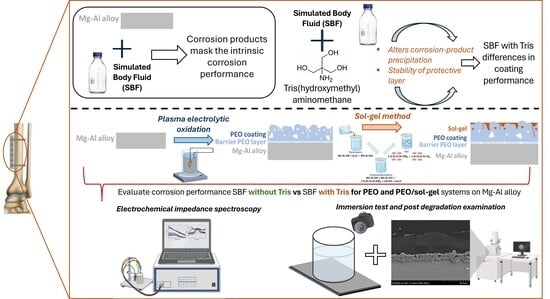
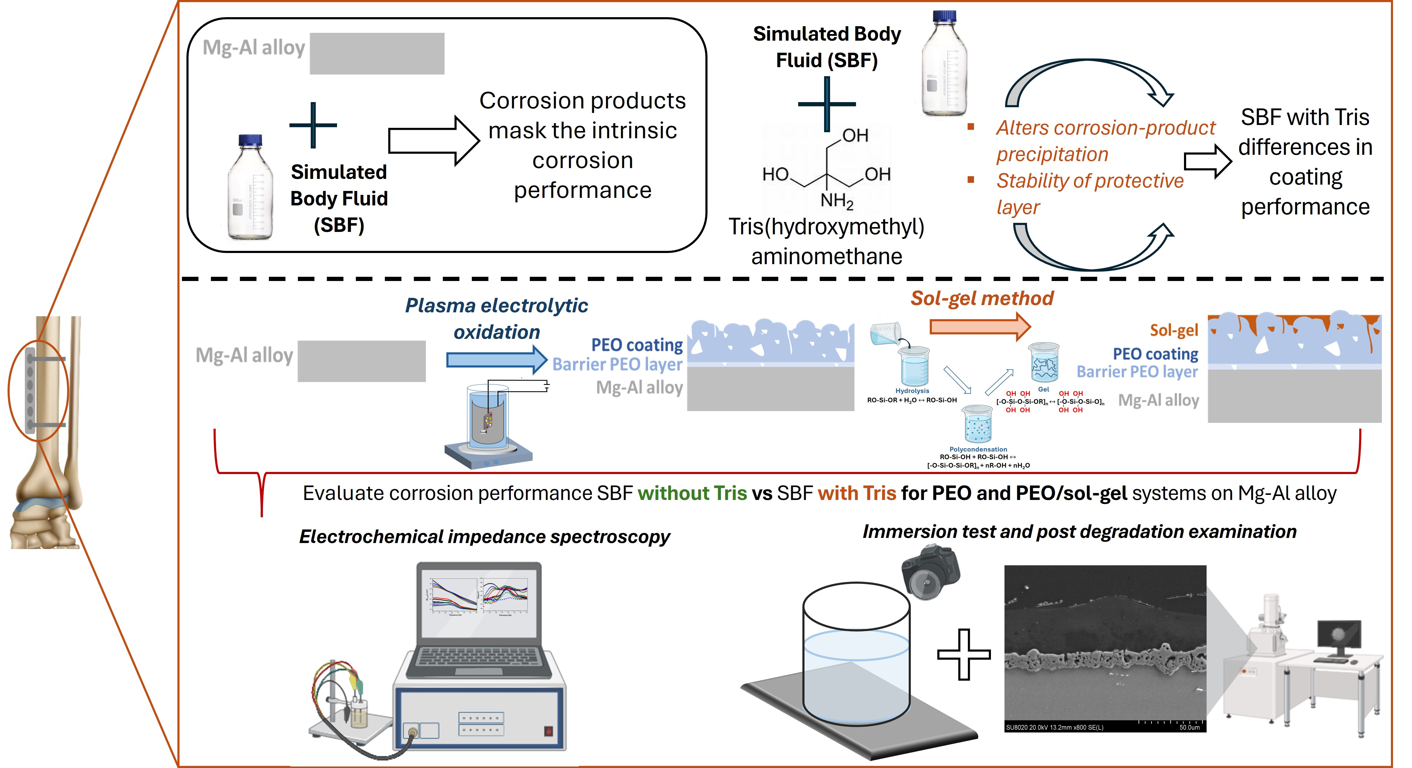
Magnesium alloys are promising candidates for biomedical implants, but their rapid corrosion limits clinical use. Simulated body fluid (SBF) is commonly used to evaluate corrosion behaviour; however, Ca-P and carbonate deposits can mask the intrinsic performance of protective coatings. Tris(hydroxymethyl)aminomethane (Tris) has been proposed as an SBF modifier, although its effect on coated magnesium remains poorly understood. While Tris modifies the buffering characteristics of the solution, it also alters the stability of Mg(OH)2 and the precipitation equilibria of corrosion products, resulting in more aggressive corrosion conditions than standard SBF. Here, the corrosion behaviour of AZ31 alloy, a plasma electrolytic oxidation (PEO) coating, and a sol-gel sealed PEO coating was investigated in SBF with and without Tris. Electrochemical impedance spectroscopy, immersion tests, pH monitoring, and post-immersion SEM/EDS analyses were used to evaluate coating performance under physiological and aggressive conditions. The results show that AZ31 and PEO coatings exhibit higher apparent corrosion resistance in SBF without Tris due to corrosion-product stabilization and Ca-P-rich deposits that partially block electrolyte access. In contrast, SBF with Tris accelerates degradation, causing uniform corrosion of AZ31 and premature PEO failure through electrolyte penetration and coating cracking. The PEO-AR/ZTP system maintains the highest electrochemical resistance and the best protective performance in both media.

Graphical Abstract

1. Introduction

In recent decades, magnesium and its alloys have had a significant transformation, becoming biodegradable metallic biomaterials for orthopedic applications. This development represents a significant change compared to conventional materials used as biodegradable implants [1]. In contrast to other metals—such as titanium, zirconium or iron alloys—magnesium alloys offer the advantage of gradual degradation in physiological conditions, eliminating the need for a secondary surgery to remove the implant once healing is completed [2,3,4]. Their density (~1.74 g/cm3) and elastic modulus (41–45 GPa) are close to the cortical bone (1.8–2.1 g/cm3, 15–40 GPa), minimizing stress shielding effects that often cause bone resorption and implant loosening [5,6]. Additionally, magnesium plays an essential role in enzymatic reactions involved in bone metabolism, contributing to osteoblast proliferation, differentiation, mineralization, and improved osseointegration [7]. Despite these advantages, magnesium alloys suffer from quick corrosion under physiological conditions. Accelerated degradation leads to a premature loss of mechanical integrity before complete bone healing, while excessive hydrogen evolution can result in gas pockets, tissue damage, and local alkalisation triggering inflammatory responses [8]. The protective Mg(OH)2 layer formed during the corrosion process is unstable in chloride-rich environments, promoting continuous dissolution and limiting the use of magnesium implants to low-load applications such as screws or plates [9].
Plasma electrolytic oxidation (PEO) is widely used to enhance the surface properties of magnesium alloys [10]. Under high voltage, local plasma discharges form a ceramic oxide layer with a dual-layer structure: a relatively compact inner barrier providing corrosion protection, and a porous intermediate-outer layer enabling bioactivity [11,12]. The composition, thickness, and morphology of PEO coatings can be modulated by adjusting electrical parameters of the process, electrolyte composition, and processing time. These properties allow the incorporation of bioactive elements (i.e., Ca, Si, P, F) into the oxide layer, enhancing tissue compatibility, mechanical characteristics and barrier properties [13,14,15,16]. Nevertheless, the porous morphology, especially when formed under high-voltage (denominated arc regime), creates interconnected channels that can facilitate electrolyte penetration and allow early onset of localized corrosion at the PEO–substrate interface. However, “soft regimes” produce more compact coatings with lower internal porosity, but tend to compromise pore interconnectivity, which can limit the subsequent infiltration of other coatings [17]. The balance between the porosity required for functional infiltration and the compactness that guarantees barrier properties remains a key challenge [18,19].
To overcome this limitation, the sol-gel method has become an attractive post-treatment approach. The sol-gel process converts liquid sols into solid hybrid or inorganic oxide networks through hydrolysis and condensation reactions of metal alkoxide precursors [20,21]. This method offers advantages for orthopedic implants, as it operates under mild processing conditions that maintain the structure of the PEO coating, allows control of the composition and thickness of the coating, and permits the formation of continuous and uniform layers with superior corrosion resistance [22]. Sol-gel films are particularly advantageous for sealing PEO coatings due to their ability to penetrate and fill pores and cracks, forming a system that enhances corrosion protection and maintains biocompatibility [23]. Common silica-based precursors include tetraethyl orthosilicate (TEOS) and tetramethoxysilane (TMOS), which form the inorganic silica network, while organofunctional silanes such as 3-glycidoxypropyltrimethoxysilane (GPTMS) and 3-methacryloxypropyltrimethoxysilane (MAPTMS) are often incorporated to improve chemical bonding and mechanical flexibility of the coatings [24,25]. Additionally, metal alkoxides like zirconium (IV) tetrapropoxide (ZTP) are frequently used to enhance corrosion properties by forming dense zirconia–silica hybrid networks [26]. These precursors and their combinations enable the fabrication of multifunctional coatings that simultaneously improve corrosion protection and biological performance. Recent studies demonstrate significant improvements in corrosion performance for duplex PEO/sol-gel coatings on magnesium alloys [27,28,29,30,31,32,33,34,35], but often lack detailed correlation between PEO microstructure, sol-gel penetration, and actual electrochemical performance.
In the previous study, we demonstrated that the PEO electrical regime decisively governs the penetration of sol-gel networks [36]. The arc PEO regime presented highly interconnected channels that allowed for deeper and more homogeneous infiltration compared to the soft PEO regime, which was more superficial, according to SEM and mechanical analyses. These findings provide the structural basis for the present work, which focuses specifically on arc-PEO and arc-PEO/sol-gel duplex coatings and investigates their corrosion behaviour under physiologically relevant but chemically stabilized conditions.
More generally, the performance and durability of protective surface systems are governed not only by the intrinsic properties of the coating but also by the coupled interactions between the surrounding medium, interfacial transport processes and surface-film evolution. Similar concepts have been discussed across different areas of surface engineering, highlighting the importance of medium chemistry in determining interfacial behaviour and long-term functional performance [37,38].
A critical yet often overlooked aspect in magnesium corrosion studies is the selection of the testing medium [39]. Commonly used electrolytes, such as sodium chloride (NaCl), phosphate-buffered saline (PBS), or simulated body fluid (SBF) are employed to simulate physiological environments, although their chemical composition also influence the corrosion behaviour observed. During magnesium degradation, these media may promote precipitation of magnesium hydroxide (Mg(OH)2), carbonates, and phosphate-containing phases, which may partially mask the initial response to the degradation of coated magnesium systems. Consequently, corrosion products and calcium-phosphate-rich deposits may partially block electrolyte access and may increase the measured electrochemical impedance, complicating the interpretation of the intrinsic barrier behaviour of protective coatings [40,41,42]. To minimize the impact of precipitation-related artefacts while maintaining a physiologically inspired environment, the studies have introduced Tris (tris(hydroxymethyl)aminomethane) (denominated as Tris) as a buffering agent in magnesium corrosion test. Tris helps to moderate the increase in pH during magnesium dissolution and provides a more controlled chemical environment to distinguish differences in degradation behaviour between surface treatments [43,44,45]. However, Tris is not chemically inert towards magnesium corrosion, as it can influence the stability of Mg(OH)2 and the precipitation of corrosion products, including Ca-P-containing phases, thereby modifying the degradation behaviour of magnesium alloys. Consequently, Tris-containing SBF should not be regarded as a non-interfering physiological medium but rather as a chemically more aggressive and discriminating electrolyte for evaluating corrosion resistance of magnesium-based systems [46,47]. This distinction is particularly important when evaluating protective coatings, as the surface deposits that form in SBF without buffering agents can partially mask differences in coating performance.
Although Tris-modified solutions have previously been used to investigate the corrosion behaviour of bare magnesium alloys [48], coated magnesium systems [49], PEO and duplex PEO/sol-gel coatings, have received much less attention. Since the degradation behaviour of these coatings is strongly influenced by electrolyte chemistry and surface-film formation, comparing their performance in SBF without and with Tris provides valuable insight into how the testing medium influences corrosion resistance. Therefore, the objective of the present work is not to validate Tris-containing SBF as a universal physiological medium, but to compare the corrosion behaviour of AZ31, PEO and duplex PEO/sol-gel coatings in SBF electrolytes without Tris and with Tris. This comparison aims to improve the interpretation of coating degradation by considering the influence of corrosion-product deposition and electrolyte chemistry on the measured corrosion response.
In this work, the corrosion behaviour of bare AZ31, PEO-AR and PEO-AR/sol-gel duplex coatings was investigated in SBF without Tris and with Tris. Electrochemical impedance spectroscopy was used to evaluate the evolution of the barrier properties during one week of immersion, while two-week immersion tests combined with pH monitoring and post-immersion SEM/EDS analyses, were employed to characterize coating degradation. By comparing the responses obtained in both electrolytes, this work aims to (i) evaluate the protective behaviour of the duplex coating, (ii) assess how the chemistry of the testing medium influences the interpretation of corrosion performance, and (iii) provide further insight into the relationship between PEO microstructure, sol-gel sealing and coating degradation.

2. Materials and Methods

2.1. Materials

AZ31 magnesium alloy sheets (supplied by KG Fridman AB, Karlstad, Sweden) were selected for this study. The composition is (wt%): Al 2.5–3.5, Zn 0.7–1.3, Mn 0.2, and minor constituents including Si, Cu, Ca, Fe, Ni, with Mg as the remainder. Rectangular samples of 6 cm × 6 cm × 0.5 cm were prepared and subjected to an acid pre-treatment based on immersion in 2 M HNO3 for 40 s, followed by 0.25 M HNO3 for 30 s to remove surface oxides and contaminants, after which specimens were dried using pressurized air.
All reagents utilized in the sol-gel synthesis were 3-(trimethoxysilyl)propyl methacrylate (MAPTMS), tetraethyl orthosilicate (TEOS), zirconium tetrapropoxide (ZTP), methacrylic acid (MAA), 1-propanol (all Sigma-Aldrich), and hydrochloric acid (AppliChem).

2.2. PEO Treatment

Plasma electrolytic oxidation (PEO) was carried out with a bipolar power supply (Micronics Systems, Villette-d’Anthon, France), using a squared pulsed regime with 400 V of maximum voltage and with an anodic cycle of +4.2 A and a cathodic cycle of −3.6 A for 5 ms, followed by a Toff of 3 and 2 ms, respectively [50]. The duty cycle and frequency were maintained at 66.7% and 66.7 Hz with a total treatment time of 30 min. Electrolyte composition consisted of 8.4 g/L KOH, 10.5 g/L Na2SiO3, and 1.7 g/L NaF dissolved in demineralized water, and the process was conducted in a double-walled 3 L vessel (Lenz LF150, Reagecon Diagnostics Ltd., Lismacleane, Ireland), temperature stabilized below 20 °C using a recirculating cooler system (VWR MX 7L R-20, VWRTM part of Avantor, Rosny-sous-Bois, France).

2.3. Sol-Gel Treatment

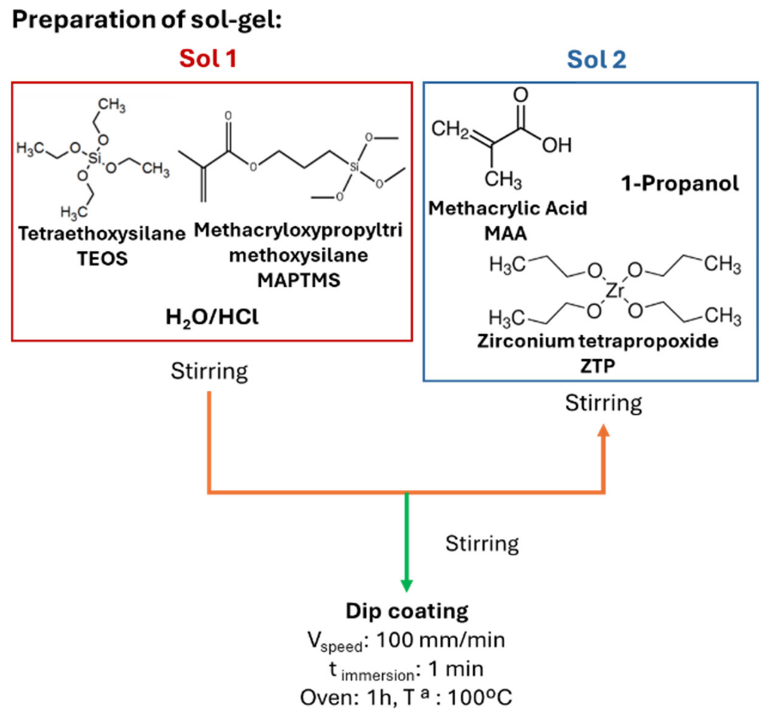
The hybrid sol-gel layer preparation followed a two-step protocol from Peter et al. [51], as described in Figure 1. A silica-based solution (sol 1) containing TEOS (0.18 mol) and MAPTMS (1 mol) was hydrolysed with distilled water (2.075 mol) and HCl (0.001 mol, catalyst), under vigorous stirring for 2 h. A second solution (sol 2) was prepared with ZTP (0.12 mol), MAA (0.12 mol) and 1-propanol (0.4 mol), stirred for 30 min. Subsequently, sol 1 was slowly added to sol 2; the mixture was stirred for 24 h. PEO-AR coated sample was dip-coated in the final sol solution for 1 min (withdrawal rate: 100 mm/min during 1 min of immersion), then cured at 100 °C for 1 h.

2.4. Surface Characterization

The composition and morphology of the samples were evaluated using a scanning electron microscope (SEM, Hitachi SU8020, Hitachi High-Tech Corporation, Tokyo, Japan), equipped with an X-ray energy dispersive system (EDS, Thermo Scientific Noran System 7, Thermo Fisher Scientific, Waltham, MA, USA). The cross-section of the samples was prepared by means of a grinding process using SiC abrasive papers ranging from P240 to P1200 grit, followed by polishing with diamond paste, from 3 to 1 μm.
The coating thickness was measured using the Fischer ISOSCOPE FMP10 (Helmut Fischer GmbH, Sindelfingen, Germany) (portable eddy current meter by averaging ten measurements taken at different locations on each sample. The thickness values were also verified by measuring ten different locations on SEM cross-sectional images of the PEO-AR and PEO-AR/ZTP coatings. The pore size of the PEO-AR coating was determined from the longitudinal section of three independent SEM images using ImageJ v1.54t software (2026). The reported values correspond to the average of thickness and pore size obtained from these measurements.
Roughness measurements have been achieved by means of the Hirox KH-8700 digital microscope (Hirox Co., Ltd., Tokyo, Japan), the means of five measurements being reported.

2.5. Corrosion Tests

The corrosion performance of all the samples was analyzed by electrochemical impedance spectroscopy and immersion tests in a home-made SBF (Simulated Body Fluid) solution without and with tris-(hydroxymethyl) aminomethane (Tris). The SBF without Tris contains 8.035 g/L NaCl, 0.355 g/L NaHCO3, 0.225 g/L KCl, 0.231 g/L K2HPO4·3H2O, 0.311 g/L MgCl2·6H2O, 0.292 g/L CaCl2, and 0.0722 Na2SO4, where the pH was adjusted to 7.0 using 1 M HCl at 37 °C. Meanwhile, the SBF with Tris is composed of 8.035 g/L NaCl, 0.355 g/L NaHCO3, 0.225 g/L KCl, 0.231 g/L K2HPO4·3H2O, 0.311 g/L MgCl2·6H2O, 0.292 g/L CaCl2, and 0.0722 Na2SO4 and 6.118 g/L Tris, and the pH was adjusted to 7.0 using 1M HCl at 37 °C. For all corrosion tests, the solution was not renewed and no CO2 was applied to maintain or adjust the pH at 7.0 during all the tests.
After testing, the samples were washed with deionized water and dried with compressed air to analyze the corrosion morphology. All corrosion tests, including EIS measurements, immersion tests, and pH monitoring, were performed in duplicate to ensure reproducibility. Representative EIS spectra and immersion photographs are presented in the manuscript, as the samples evaluated exhibited similar tendency with only minor differences.
EIS measurements were taken over a one-week immersion period, with data collected at 2, 24, 48, 72 and 96 h and at one week, using an SP-300 potentiostat (BioLogic, Seyssinet-Pariset, France) and a standard three-electrode setup in a Faraday cell. This system consists of an Ag/AgCl-3M reference electrode, platinum counter, and the sample (bare AZ31, PEO-AR, and PEO-AR/ZTP system) with 1 cm2 exposed surface as working electrode. A sinusoidal voltage of ±10 mV peak to peak amplitude was applied in the frequency range from 100 kHz to 10 mHz. The EIS spectra were fitted using equivalent electrical circuits selected according to the spectral features observed for each sample and immersion time. Fit quality was evaluated using the chi-squared ( χ 2 ) and sum of squared residuals values reported by the ZView v.40h software (2026), together with the visual agreement between experimental and fitted spectra. As a practical criterion, χ 2 values below 0.01 were considered acceptable. The selected circuits were chosen to capture the main electrochemical processes at the coating/electrolyte interface, and the corresponding elements are interpreted as phenomenological descriptors rather than unique physical layers.
The immersion test was carried out by immersing the prepared samples in 30 mL SBF at 37 °C for 2 weeks, using 80 mL plastic tubes affixed to the sample surface (exposed area: 7.1 cm2). Macroscopic monitoring using digital photographs allowed the progression of corrosion to be tracked over time, with images captured at 6, 24, 48, 72 and 96 h, and at one and two weeks of immersion. Figure 8 shows only the most representative photographs for each of the samples and time points studied, as no noticeable differences were observed between the two replicates. The solution pH was monitored at 2, 6, 24, 48 and 96 h, and at 1 and 2 weeks to record variations associated with surface reactions and changes in solution chemistry. The reported pH values correspond to the average of two different measurements.

3. Results

3.1. Characterization of the PEO and Duplex PEO/Sol-Gel Systems

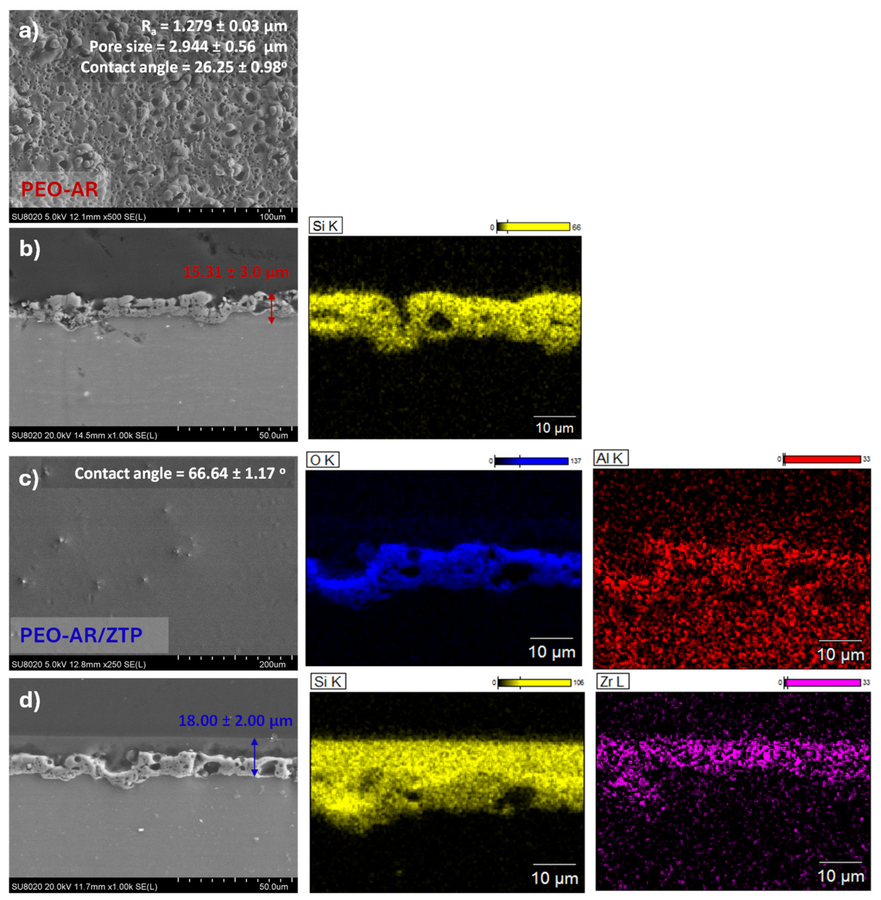
Figure 2 shows the surface (Figure 2a,c) and cross-sectional (Figure 2b,d) morphologies and the elemental distribution maps of the PEO samples obtained under arc conditions (Figure 2a,b) and the PEO sealed with the sol-gel coating, PEO-AR/ZTP (Figure 2c,d).
In Figure 2a, the PEO coating produced under the arc regime (PEO-AR) exhibits large, irregular discharge pores (average pore size ≈ 2.9 ± 0.6 µm) and high surface roughness (Ra = 1.28 ± 0.03 µm), reflecting intense plasma activity and localized melting-solidification phenomena. In the duplex system (PEO-AR/ZTP, Figure 2c), the sol-gel layer uniformly covers the PEO surface, resulting in a smoother and more homogeneous topography. Cross-sectional analysis of the PEO-AR coating (Figure 2b) reveals the characteristic multilayered structure, consisting of a dense inner barrier layer, an intermediate transition zone, and an outer porous region. The average thickness of the PEO coating is 15.31 ± 3.0 μm (PEO-AR), while that of the total thickness of PEO-AR/ZTP (Figure 2d) is slightly higher, around 18.00 ± 2.00 µm. This slight increase in total thickness can be associated with the deposition of the sol-gel layer and its partial infiltration into the interconnected pores of the arc-regime PEO coating, which makes the exact determination of the original PEO outer surface difficult.
EDS mapping of PEO-AR coating shows the presence of Si, and O, consistent with the incorporation of silicate species from the electrolyte and the formation of oxygen-rich magnesium phases, as commonly reported for PEO coatings produced in silicate-based electrolytes [50]. In contrast, the PEO-AR/ZTP duplex system exhibits an enrichment of Si, Zr, O, and Al in the outer region of the coating, confirming the deposition of the Zr-Si hybrid sol-gel layer. Moreover, the distribution of Zr and Si throughout the porous region of the PEO coating suggests partial infiltration of the sol-gel into the interconnected porosity. This interpretation is consistent with the chemical and morphological characterization previously reported for this coating system. FTIR analyses confirmed the formation of the hybrid Zr-Si network and SEM/EDS observations demonstrated the penetration of the sol-gel into the porous PEO structure [26,52].

3.2. Electrochemical Impedance Spectroscopy (EIS)

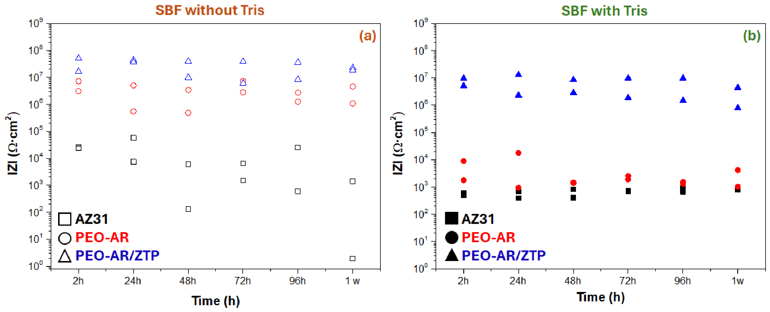
Figure 3 illustrates the evolution of the electrochemical impedance modulus at low frequencies (|Z|10mHz) at different immersion times for AZ31 alloy, PEO-AR coated and PEO-AR/ZTP samples in Figure 3a SBF without Tris and Figure 3b SBF with Tris at 37 °C.
-
SBF Without Tris
In Figure 3a, PEO-AR and PEO-AR/ZTP samples immersed in SBF without Tris present higher modulus of total impedance at a low frequency (|Z|10mHz of PEO-AR: 7.19·106 Ω·cm2 and PEO-AR/ZTP: 5.04·107 Ω·cm2 after 2 h), by 2 orders of magnitude compared to AZ31 alloy (|Z|10mHz: 2.64·104 Ω·cm2 after 2 h). This indicates the higher initial corrosion resistance provided by both coating systems compared with the bare alloy. It should be noted that, although the PEO-AR has a high |Z|10mHz value after 2 h, it is slightly lower than that of the sample sealed with the sol-gel, which may be associated with the sealing of interconnected pores within the PEO coating. With the increase in immersion time, the impedance modulus of the coated systems decreases progressively (i.e., |Z|10mHz PEO-AR: 7.19·106 Ω·cm2 from 2 h to 4.59·106 Ω·cm2). This decrease may be associated with electrolyte penetration through pores and coating defects together with the progressive evolution of the formation of corrosion products during immersion. In the case of the AZ31 alloy, the increase in the values may be related to the formation of corrosion products. Comparing PEO-AR and PEO-AR/ZTP, the difference in values is not very pronounced, but PEO-AR/ZTP shows better corrosion resistance after 1 week of immersion (|Z|10mHz of PEO-AR: 4.59·106 Ω·cm2 and PEO-AR/ZTP: 1.84·107 Ω·cm2). This subtle difference may be explained by the good corrosion protection of the PEO-AR under lower aggressive conditions provided by SBF without Tris and consequently the lower sol-gel contribution.
-
SBF with Tris
In Figure 3b, the PEO-AR/ZTP in the SBF with Tris has a modulus of impedance at a low frequency of 3 orders of magnitude higher (|Z|10mHz of PEO-AR/ZTP: 9.74·106 Ω·cm2) than that of AZ31 and PEO-AR coating (|Z|10mHz of AZ31: 5.91·102 Ω·cm2 and|Z|10mHz of PEO-AR: 8.87·103 Ω·cm2) after 2 h of immersion. This confirms that the double layer of PEO+sol-gel has a high protective capacity due to the effective sealing of the PEO porosity by the sol-gel layer, as was discussed before in Figure 2d. In addition, the modulus of impedance of all samples decreases with the immersion time (i.e., |Z|10mHz of PEO-AR: 8.87·103 Ω·cm2 from 2 h to 9.32·102 Ω·cm2 after 1 week). However, in the case of the PEO-AR/ZTP sample, it remains within the same order of magnitude throughout the test (|Z|10mHz: 9.74·106 Ω·cm2 from 2 h to 4.15·106 Ω·cm2 after 1 week), indicating that the duplex coating retains a substantially higher corrosion resistance than the other investigated systems. While in the case of PEO-AR, this could be due to the penetration of the medium into the pores and defects in the ceramic coating, as seen in Figure 2b. It should be noted that PEO-AR has values (|Z|10mHz: 932.20 Ω·cm2) similar to those of the AZ31 (|Z|10mHz: 677.02 Ω·cm2) after 24 h of immersion, showing a corrosion behaviour similar to that of AZ31 until the end of the test. This suggests that PEO layer gradually loses its protective effectiveness as it is penetrated by corrosive species present in the medium, leading to a gradual loss of the coating’s protective effect during this first 24 h of immersion, which continues as the exposure time increases [50].
-
Comparison SBF without vs. with Tris
According to the influence of Tris in the SBF solution, the results suggest that the presence of Tris significantly modifies the corrosion behaviour of the AZ31 and PEO coating sample. Both AZ31 and PEO-AR samples exposed to the Tris exhibit a low modulus of impedance at low frequency of 1–3 orders of magnitude, depending on the sample (i.e., PEO-AR-non-tris: 7.19·106 Ω·cm2 and PEO-AR-tris: 8.87·103 Ω·cm2 after 2 h) compared to the SBF without Tris, indicating a decrease in corrosion resistance with the immersion time. This has a significant effect on the AZ31 and PEO-AR samples, whilst its impact is less pronounced for the PEO-AR/ZTP system (e.g., PEO-AR/ZTP-non-tris: 5.04·107 Ω·cm2 and PEO-AR/ZTP-tris: 1.17·107 Ω·cm2 after 2 h), whose modulus of impedance remains within the same order of magnitude in both media during immersion. In the case of the PEO-AR coating, this behaviour could be attributed to the interconnected porosity of the PEO coating, which allows aggressive media to penetrate the substrate and accelerate the corrosion mechanism. On the other hand, the high protection provided by the duplex system could be attributed to the dual protection provided by the PEO and sol-gel layers, which acts to prevent corrosive species from accessing the interior of the system.
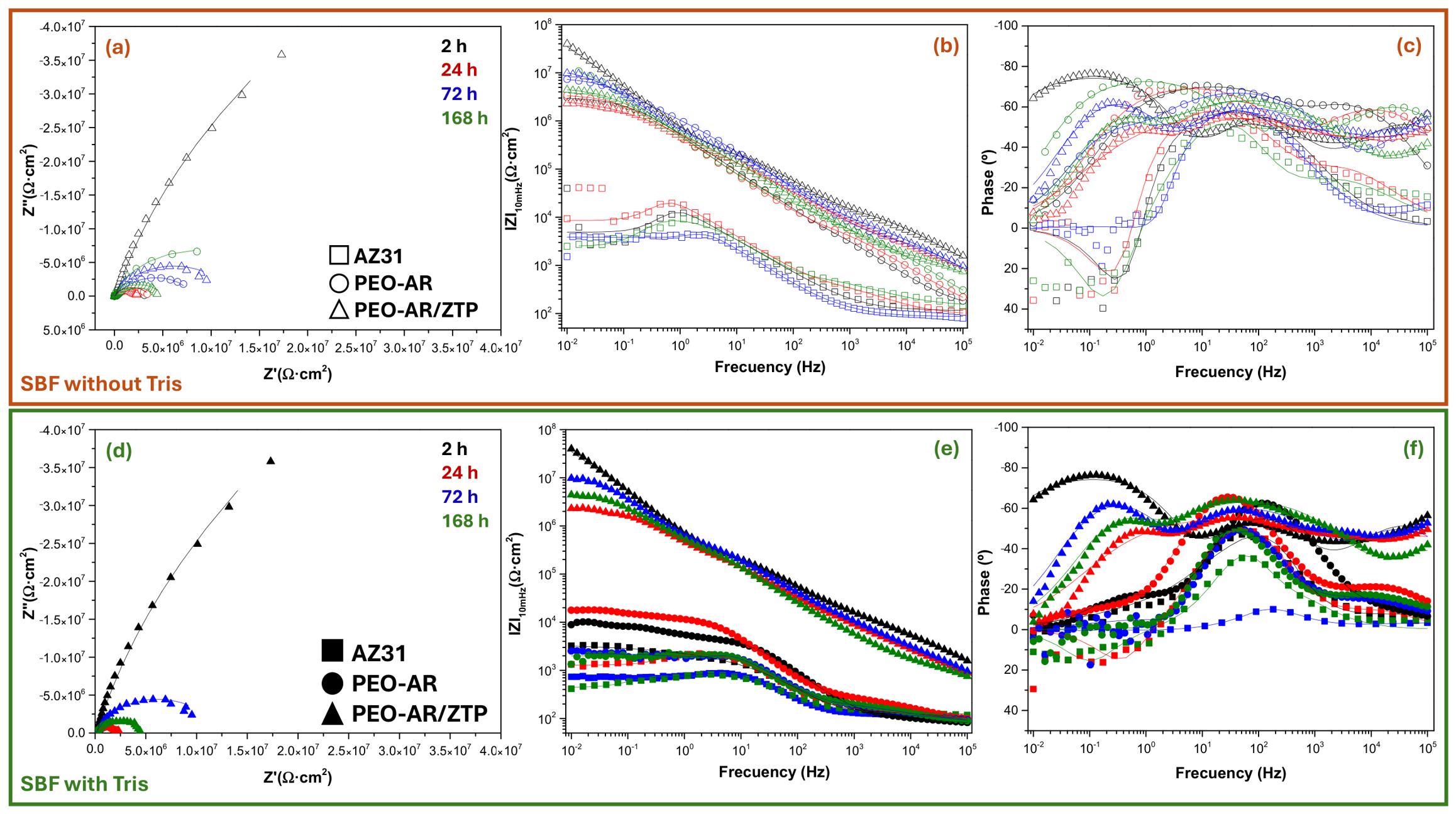
In order to understand the phenomena that occur during the corrosion process and corroborate the hypotheses described above, the equivalent circuits of each sample and immersion time are analyzed in depth. Figure 4 shows the Figure 4a,d Nyquist and Figure 4b,c,e,f Bode diagrams for all samples studied only after 2, 24, 72, and 168 h of immersion in Figure 4a–c SBF without Tris and Figure 4d–f SBF with Tris. The results are fitted using different equivalent circuits, as shown in Figure 5, and the electrochemical parameters extracted are displayed in Table 1.
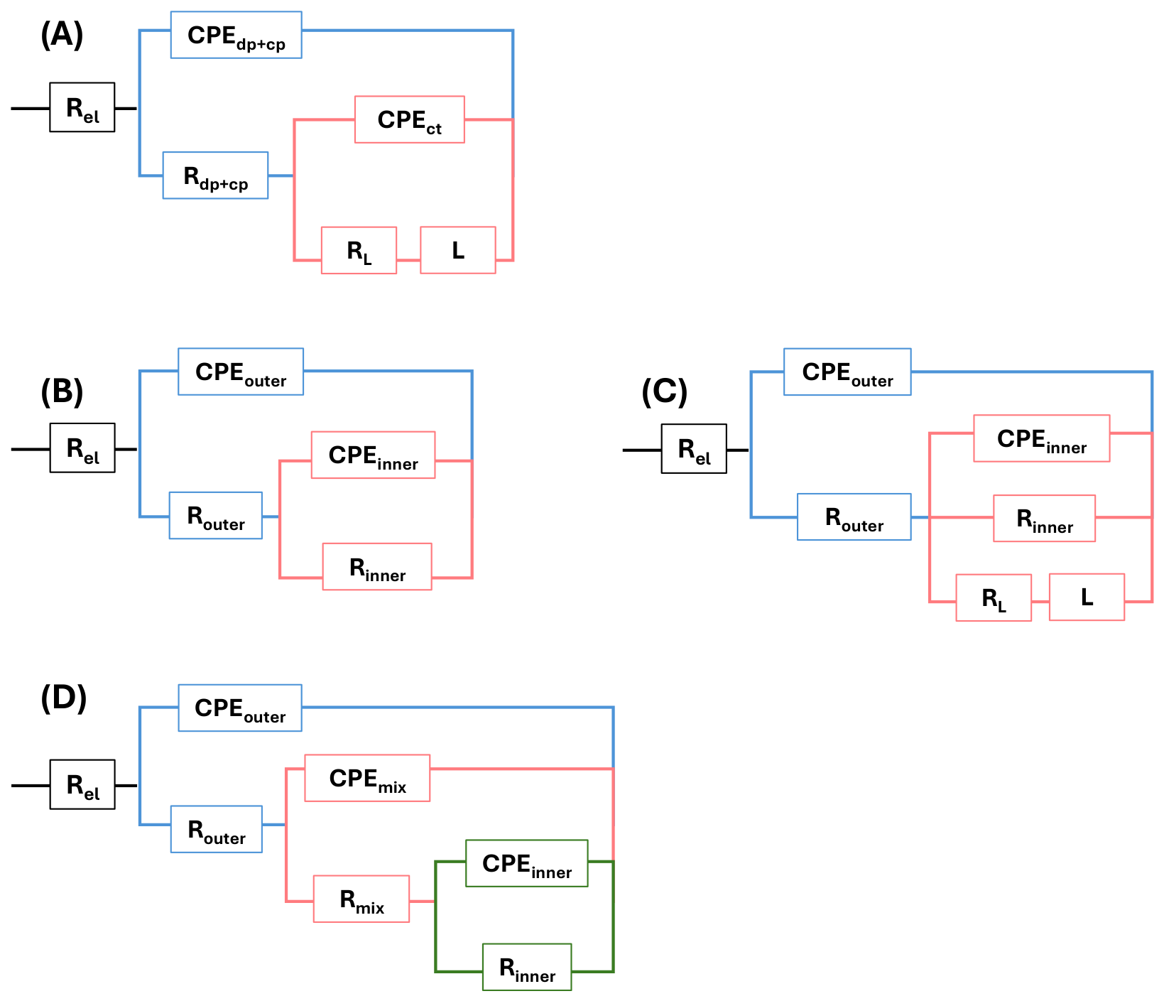
The equivalent electrical circuits (EEC) used to fit the impedance spectra are shown in Figure 5. The selected models were chosen according to the electrochemical response observed during immersion and the appearance or disappearance of characteristic time constants in the Nyquist and Bode diagrams. It should be noted that the equivalent-circuit elements represent phenomenological electrochemical processes rather than unique physical layers.
The response of the AZ31 (Figure 5A, Model A) incorporates the following elements: Rel associates to the resistance of the electrolyte, CPEdp+cp/Rdp+cp, which represent the resistance and capacitance associated with the compounds deposited (dp) on the surface and the corrosion products (cp) formed during the test. The CPEct component is assigned to the electrochemical phenomena that occur at the substrate/electrolyte interface, including double-layer capacitance and charge-transfer phenomena (ct). In addition, the presence of the RL/L is commonly associated with adsorption/desorption processes of intermediate species during magnesium dissolution and has frequently been reported for actively corroding Mg alloys [53].
For the PEO-AR coating, the EEC (Figure 5B, Model B) consists of Rele, CPEouter/Router, which describes the capacitive and resistive response of the outer and intermediate layers of the PEO coating, and CPEinner/Rinner is associated with the capacitive and resistive behaviour of the barrier layer. In addition, in the case of SBF with Tris for PEO-AR, after 24 h of immersion, an additional RL/L is included in the Model B (Figure 5B) and its transforming into Model C (Figure 5C). This inductive contribution is associated with relaxation processes accompanying electrolyte penetration through the porous coating and the adsorption of intermediate species during localized corrosion, as previously described in some studies [54].
In the case of PEO-AR/ZTP system (Figure 5D, Model D), the EEC is modelled using three branches, CPEouter/Router corresponds to the capacitive and resistive response of the sol-gel layer, CPEmix/Rmix is associated with the interfacial region resulting from the partial infiltration of the sol-gel into the porous PEO structure (mix = PEO + sol-gel), and CPEinner/Rinner represents the capacitive and resistive behaviour of the PEO barrier layer. This model provides a phenomenological description of the multilayer electrochemical response of the duplex coating on aluminum alloys [26,55].
The roughness and heterogeneity of the surfaces generate non-ideal interfaces, so a constant phase element (CPE) is used instead of an ideal capacitor to interpret the EIS results. The impedance of the CPE is calculated by the following expression: Z = 1/(Y0(j·ω)n), where n is the frequency dispersion factor, which varies between 0 ≤ n ≤ 1, and Y0 is the admittance of the CPE.
-
SBF without Tris
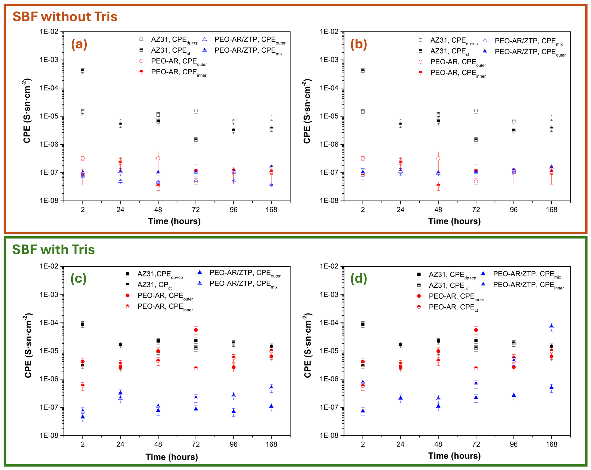
In SBF without Tris (Figure 4a–c), the bode diagram of the AZ31 shows two-time constants after 2 h of immersion. The first, located in the high-frequency, corresponds to the CPEdp+cp/Rdp+cp part (Model A, Figure 5A), and the second time constant corresponds to the CPEct/RL-L pair located in the mid-frequency range (see Figure S1a–c, for more details). As immersion increases, the two-time constants widen and shift towards lower frequencies, reflecting a progressive deterioration of the corrosion products and the metal/electrolyte interface. This evolution is manifested in the decrease in Rdp+cp and RL (Figure 6a,b). Accordingly, Rdp+cp (associated with the Mg(OH)2 layer and deposits products formed between the reaction of Mg and species present in the medium) decreases from 2.1·104 to 582 Ω·cm2, while RL (related to the resistance to charge transfer at the active interface) shows an overall decreasing trend from 6.1·103 to 3.1·103 Ω·cm2, despite fluctuations at intermediate times (Figure 6a). This dual decrease indicates that the corrosion products film becomes progressively more porous and permeable and the underlying interface is electrochemically activated, favouring both uniform and localized dissolution mechanisms. Correspondingly, CPEdp+cp decreases from 1.42·10−5 to 9.03·10−6 S·sn·cm−2, together with the decrease in its phase exponent ndp+cp from 0.72 to 0.62, and this indicates a less homogeneous and more defective surface film (Figure 7a and Figure S2a). Likewise, CPEct decreases from 4.02·10−4 to 3.7·10−6 S·sn·cm−2 (Figure 7b), accompanied by a slight decrease in nct from 0.98 to 0.90, suggesting a reduction in the effective interfacial capacitance, while reflecting increasing interfacial heterogeneity. Overall, these changes indicate progressive weakening of the Mg(OH)2 layer, enhanced electrolyte penetration, and the early onset of localized dissolution in SBF without Tris. These findings are consistent with previous reports on the instability of magnesium hydroxide films in SBF solution [56].
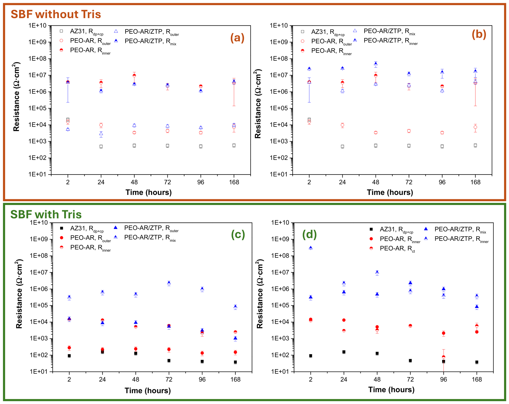
In the case of the PEO-AR coating, the bode diagram shows two-time constants, reflecting the bilayer structure of the PEO coatings (Figure 5B, Model B). The high-frequency time constant (CPEouter/Router) corresponds to the porous outer-intermediate layer, while the medium-frequency time constant (CPEinner/Rinner) is associated with the protective barrier layer. These results are consistent with the literature on PEO coatings on magnesium alloys [50]. After 2 h of immersion, the PEO-AR coating has values of Router: 1.55·104 Ω·cm2 and Rinner: 3.90·106 Ω·cm2, indicating the high initial resistance of both parts. With the increase in time of immersion, Router gradually decreases to 7.30·103 Ω·cm2, whereas Rinner remains within the 106 Ω·cm2 range after one week of immersion (Figure 6a,b), demonstrating that the barrier layer retains its protective character despite partial hydration of the outer part of the coating. The capacitive parameters support this behaviour, with CPEouter decreasing from 3.21·10−7 to 1.03·10−7 S·sn·cm−2 and CPEinner slightly increasing from 8.15·10−8 to 1.06·10−7 S·sn·cm−2 (Figure 7a,b). Likewise, nouter (0.62–0.78) and ninner (0.78–0.92) fluctuate throughout immersion (Figure S2a,b), reaching minimum values after 48 and 96 h, respectively, before returning close to their initial values at 168 h. This behaviour suggests transient changes in the heterogeneity of both layers rather than progressive degradation.
The behaviour of the PEO-AR system is modified by the incorporation of the ZTP sol-gel layer, which transforms the system into a more complex multilayer structure. The PEO-AR/ZTP sample exhibits three-time constants, corresponding to the sol-gel layer (high frequency, CPEouter/Router in model D of Figure 5D), the sol-gel/PEO mix region (medium frequency, CPEmix/Rmix), and the PEO barrier layer (low frequency, CPEinner/Rinner). The additional time constant confirms the successful formation of the duplex architecture, with the sol-gel layer acting as an additional barrier. After 2 h of immersion, the Router, Rmix and Rinner are 5.25·103, 3.66·106 and 2.41·107 Ω·cm2, respectively, demonstrating the strong contribution of both the mixed region and the inner PEO layer to corrosion protection. As immersion progresses, Router increases to 9.76·103 Ω·cm2 and Rmix and Rinner remains on the order of 106 and 107 Ω·cm2 (see the evolution of resistances in Figure 6b), respectively, comparable to or higher than those of the PEO-AR coating (Router: 7.30·103 and Rmix: 3.37·106 Ω·cm2). This indicates only minor changes in the outer and mixed regions, while the inner barrier layer remains highly protective after sol-gel sealing. The capacitive parameters support this interpretation (Figure 7a,b), with ninner remaining close to 1 (0.90–0.98), consistent with a stable, compact barrier layer (Figure S2b). Finally, the absence of inductive elements, unlike in the uncoated AZ31 substrate, indicates that both PEO parts—outer and inner layers—suppress the adsorption/desorption processes associated with localized corrosion.
-
SBF with Tris
In SBF with Tris (Figure 4d–f), the electrochemical behaviour of the AZ31 is governed by a two-time constant system coupled with an inductive branch, as described by Model A in Figure 5A. This EEC is consistent with the electrochemical response of bare magnesium alloys in SBF, where corrosion activation, surface film instability and dissolution/precipitation dynamics generate not only capacitive responses at high and low frequencies (CPE dp+cp/R dp+cp and CPEct), but also the characteristic inductive loop (RL/L) arising from adsorbed intermediate species at the metal/electrolyte interface (see Figure S1d–f, for more details). The persistence of the inductive response throughout immersion indicates that the fundamental corrosion mechanism remains active in SBF with Tris. After 2 h, the lower value of R dp+cp (91.8 Ω·cm2) and RL (3.59·104 Ω·cm2) indicate the formation of a thin hydroxide-based surface layer together with the presence of adsorbed Mg+ or MgOH+ species. With the increase in immersion time, both time constants broaden and shift towards lower frequencies, reflecting progressive destabilization of the surface film (Figure 6c,d). Rdp+cp initially increases to 157.1 Ω·cm2 after 24 h before decreasing to 37.9 Ω·cm2 over longer immersion times, indicating repeated dissolution/reprecipitation of the corrosion products (Figure 6c). Likewise, RL decrease overall to 6.21·102 Ω·cm2 despite marked fluctuations, while L decreases from 1850 to 1510 H·cm2, with a pronounced dip to 61 H·cm2 at 96 h, suggesting continuous changes in the concentration and relaxation of adsorbed intermediates. The capacitive parameters support this behaviour (Figure 7c,d). CPEdp+cp shows an overall decrease from 8.97·10−5 to 1.47·10−5 S·sn·cm−2, although it temporarily increases between 48 and 72 h, while nouter fluctuates between 0.71 and 0.85, indicating variable surface heterogeneity (Figure S2c). Similarly, CPEct shows transient fluctuations, reaching a maximum of 1.88·10−5 S·sn·cm−2 at 96 h before decreasing (6.42·10−6 S·sn·cm−2) by the end of the test (Figure 7c,d), whereas nct remains close to 1 (0.87–0.98). Overall, these changes indicate a highly dynamic surface film undergoing repeated dissolution and reprecipitation, with charge-transfer processes that remain only partially controlled throughout immersion.
The electrochemical behaviour of the PEO-AR coating in SBF with Tris is less stable and more closely resembles that of bare AZ31, showing marked differences with respect to SBF without Tris. After 2 h of immersion, the PEO-AR exhibits two-time constants: the high-frequency CPEouter/Router, associated with the outer and intermediate porous PEO region, and the mid-frequency CPEinner/Rinner, related to the compact inner barrier layer (Model B, Figure 5B). Initially, Router and Rinner reach 280.9 Ω·cm2 and 1.46·104 Ω·cm2, respectively (Figure 6c), indicating that the barrier layer still provides partial protection despite the presence of Tris. After 24 h, however, the response changes from Model B to Model C (Figure 5C,D) and see Figure S3 for more details), reflecting progressive coating degradation. Rinner decreases from 1.46·104 Ω·cm2 (24 h) to 5.15·103 Ω·cm2 after 48 h and reaches 2.52·102 Ω·cm2 by the end of the test (Figure 6c), while Router remains relatively stable (220–280 Ω·cm2) until 72 h before decreasing to 130–150 Ω·cm2 at 96–168 h (Figure 6d). This behaviour indicates rapid penetration of the electrolyte through the coating, which is attributed to the destabilizing effect of Tris on the protective hydroxide layer and on corrosion products formed within the PEO pores. The capacitive parameters support this interpretation (Figure 7c,d). CPEouter and CPEinner show overall increases until 9.6·10−6 S·sn·cm−2 and 9.92·10−6 S·sn·cm−2, respectively, accompanied by decreases in nouter (0.81 to 0.68) and ninner (0.99 to 0.87), indicating increasing heterogeneity in both the outer and barrier layers despite transient fluctuations (Figure S2c,d). More importantly, the appearance of inductive loops after 24 h (Model C, Figure 5C), absent in SBF without Tris, indicates the participation of adsorbed intermediate species (Mg+, MgOH+, MgCl+), confirming that the unsealed PEO coating cannot prevent localized corrosion. These results agree with previous studies reporting the destabilizing effect of Tris on passive films and its acceleration of magnesium corrosion in SBF [44,57].
The PEO-AR/ZTP system shows remarkable resistance compared to AZ31 and PEO-AR samples. After 2 h of immersion, the coating exhibits Router: 1.56·104 Ω·cm2 (sol-gel layer), Rmix: 3.12·105 Ω·cm2 (sol-gel/PEO mixed region) and Rinner: 2.96·108 Ω·cm2 (PEO barrier layer). Compared with SBF without Tris, Rinner is approximately one order of magnitude higher (2.96·108 vs. 2.41·107 Ω·cm2), whereas Rmix is lower (3.12·105 vs. 3.66·106 Ω·cm2), indicating that in SBF with Tris the corrosion protection relies predominantly on the PEO barrier layer rather than on the PEO/sol-gel. As immersion progresses, Rmix increases to a maximum of 2.27·106 Ω·cm2 after 72 h before decreasing to 8.28·104 Ω·cm2 by the end of the test (Figure 6c). Rinner decreases sharply after 24 h, from 2.96·108 Ω·cm2 at 2 h to 2.22·106 Ω·cm2 at 24 h, followed by a partial recovery to partially recovers at 48 h (9.81·106 Ω·cm2), and subsequently stabilizes within the 3.7–7.5·105 Ω·cm2 range (Figure 6d). Despite this decline, all resistance values remain consistently higher than those of the PEO-AR coating throughout immersion, confirming the superior protection provided by the duplex coating (Figure 6c,d). The absence of inductive loops, in contrast to the pronounced inductive behaviour observed for AZ31 and PEO-AR in SBF with Tris, indicates that the sol-gel layer effectively suppresses the electrochemical processes associated with localized corrosion. The capacitive behaviour is consistent with this interpretation (Figure 7c,d), where nouter fluctuates between 0.62 and 0.76 without a clear trend, while ninner remains close to ideal capacitive behaviour (0.90–0.98), indicating that the inner PEO barrier layer retains its protective character throughout immersion (Figure S2c,d). Pezzato et al. reported impedance values of ~105 Ω·cm2 for silica-sealed PEO on magnesium alloys [29], and Chen et al. achieved ~106 Ω·cm2 for hybrid PEO/polymer systems [58]. In the present work, Rinner exceeds these values by 1–3 orders of magnitude during the first 48 h of immersion and remains within the (~105–106 Ω·cm2) range after prolonged exposure. This behaviour suggests that the sol-gel efficiently seals the PEO pores during the early stages of immersion, although its contribution gradually decreases with time.
The EIS results reveal marked differences in the corrosion behaviour of AZ31, PEO-AR and the PEO-AR/ZTP system in both SBF without Tris and SBF with Tris.
-
For the AZ31 alloy, the impedance spectra in both media show two-time constants associated with the surface film and charge-transfer processes, together with a low-frequency inductive loop related to the adsorption and relaxation of intermediate species. However, in SBF with Tris, this response becomes more pronounced because the inductive characteristic intensifies and the resistance of the surface layer shows an overall decreasing trend, indicating reduced film stability and increased susceptibility to corrosion.
-
In the case of the PEO-AR coating, the electrochemical response highlights the limited protective capacity of the unsealed porous structure, particularly in the presence of Tris. In SBF without Tris, the system presents two-time constants with relatively stable behaviour during immersion, while the inner barrier layer maintains high resistance. In contrast, in SBF with Tris, both outer layer and the inner layer resistance decrease from the early stages of immersion, indicating progressive electrolyte penetration and loss of barrier protection.
-
In contrast, the PEO-AR/ZTP coating exhibits the most stable electrochemical behaviour among the investigated systems. In both SBF conditions, the spectra are described by a three-time constant model without inductive elements, reflecting the stabilizing contribution of the sol-gel layer. This improved behaviour is attributed to the partial sealing of the interconnected PEO porosity, which reduces electrolyte penetration, while the resistance values of the mixed region and the inner barrier layer remain higher than those of the unsealed PEO coating throughout immersion.
In all samples, Tris significantly modifies the electrochemical response by promoting surface-film destabilization and accelerating magnesium degradation. Although Tris stabilizes the solution pH, it also modifies the dissolution–precipitation equilibria involved in magnesium corrosion, affecting the stability of Mg(OH)2 and corrosion product layers and leading to faster deterioration of AZ31 and the PEO-AR coating. This effect is evidenced by the decrease in resistive parameters and the enhanced inductive or unstable behaviour observed for these systems in SBF with Tris. In contrast, the duplex PEO-AR/ZTP coating maintains the highest electrochemical resistances throughout immersion, demonstrating that the combined PEO/sol-gel architecture provides the most effective barrier among the investigated systems under the evaluated conditions.

3.3. Immersion Test

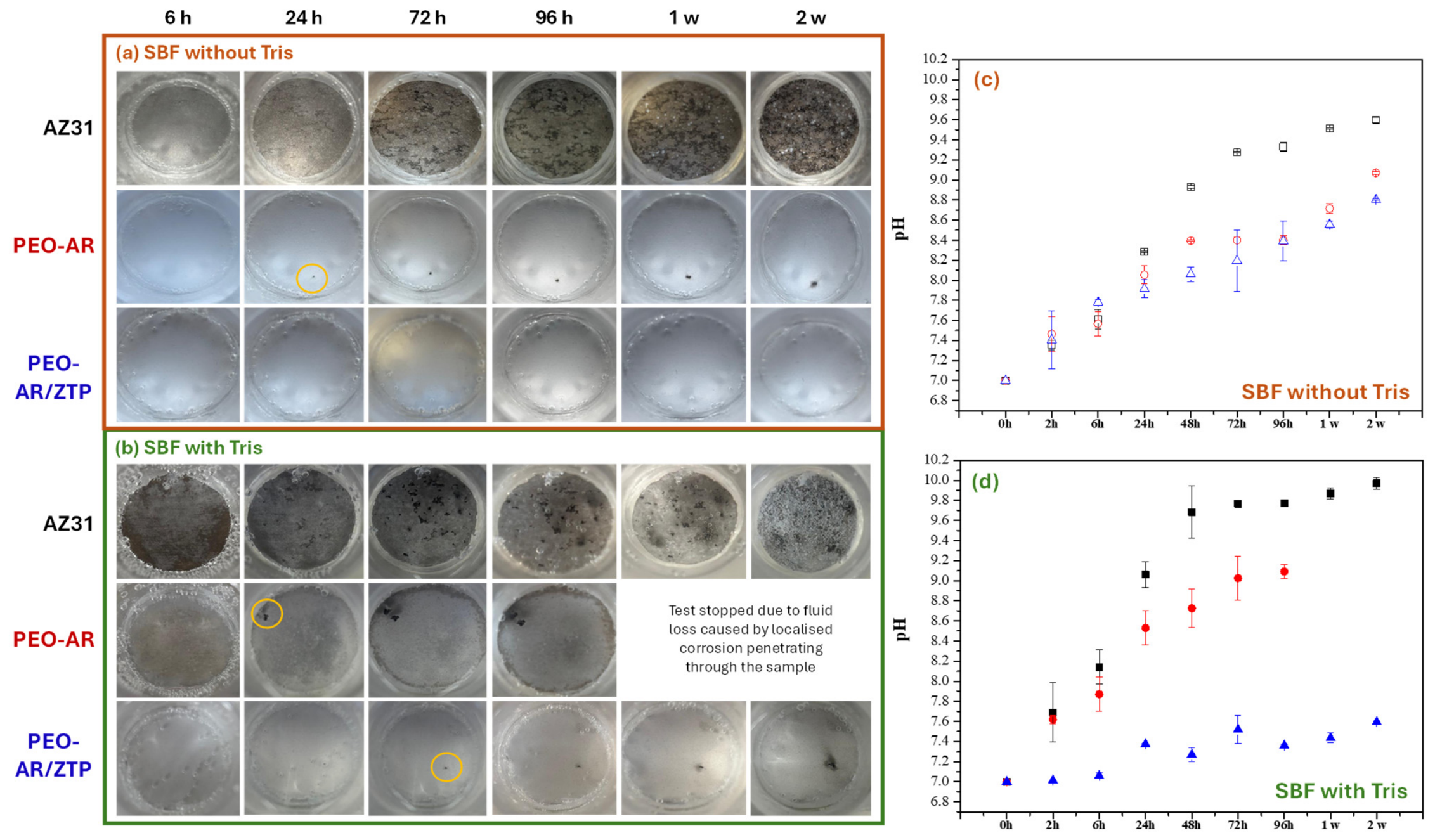
The samples are analyzed after two weeks of immersion in SBF, with and without the addition of Tris, at a temperature of 37 °C. This immersion period was selected to evaluate the degradation behaviour and stability of the coating systems under the two SBF conditions investigated within the timeframe of this study. The objective of this test is to evaluate the degradation behaviour and identify the dominant degradation mechanisms through macroscopic inspection of the samples (Figure 8a,b), monitoring the evolution of pH during immersion (Figure 8c,d), and subsequent characterization of the corrosion products formed on the surface after exposure (Figure 9 and Table 2).
-
SBF without Tris
In the SBF without Tris (Figure 8a), the AZ31 substrate shows a rapid degradation from the first 6 h of immersion, which intensifies with the immersion time due to the uniform degradation of magnesium and the formation of corrosion products on the surface (white and black products on the top). This behaviour is accompanied by an increase in pH from 7.0 to 8.2 during the first 24 h (Figure 8c), which continues to increase progressively until reaching values close to 9.6. This increase may be associated with Mg dissolution and OH generation, although additional contributions from SBF chemical equilibration and precipitation reactions cannot be excluded [59].
In the case of the PEO-AR sample, the surface appears intact for the first 24 h of immersion. After this time, localized corrosion becomes visible, suggesting progressive electrolyte penetration through pores and defects within the PEO coating and subsequent degradation of the underlying magnesium substrate. As the immersion time increases, the volume of the localized corrosion grows, thus extending the degradation of the substrate beneath the PEO layer and indicating a local reduction in the protective performance of the coating, even if the rest of the sample remains intact. This behaviour is consistent with the EIS results (Figure 4a–c, and Figure S3a–c, more details) and Table 1, which show a slight decrease in the resistance of both the porous layer (Router) and the barrier layer (Rinner) after 24 h of immersion (Figure 6a,b). The pH gradually increases from 7.0 to 9.0 due to the formation of OH groups from substrate degradation; however, it remains slightly lower than the substrate.
In the case of the PEO-AR/ZTP, the coating maintains its surface integrity throughout the immersion test, with no visible signs of localized degradation. This behaviour is consistent with the improved barrier properties provided by the duplex PEO/sol-gel architecture. And it is consistent with the results analyzed in EIS (Figure 4a–c and Table 1). Although this sample shows no visual changes, the pH of the medium increases with immersion time (see Figure 8c), in the same way as the substrate and PEO-AR samples. The increase in pH in SBF without Tris, despite the absence of visible localized or uniform corrosion on the PEO-AR/ZTP-coated sample, may also be influenced by chemical processes occurring within the electrolyte itself. Without the presence of Tris, SBF is prone to the precipitation of phosphates and carbonates due to supersaturation and ongoing ionic rearrangement in the solution. Additionally, the gradual loss of dissolved atmospheric CO2 reduces the formation of carbonic acid, further shifting the equilibrium towards H+ consumption and an alkaline pH [60]. These processes collectively raise the pH in all test samples, regardless of the extent of metal corrosion. Therefore, the pH increase should be interpreted together with the electrochemical and morphological results rather than as a direct indicator of coating degradation.
-
SBF with Tris
The immersion test in SBF with Tris (Figure 8b) shows a clear acceleration of AZ31 degradation compared to SBF without Tris. During the first 6 h, the substrate shows initial signs of corrosion, which progressively intensify throughout the immersion. This behaviour correlates with the rapid increase in pH from 7.0 to 9.2 in the first 24 h (Figure 8d), reaching values close to 9.8 after 2 weeks of immersion. The greater alkalinization observed in SBF with Tris, slightly higher than that recorded in SBF without Tris (9.8 vs. 9.6), is consistent with the more aggressive nature of the SBF with Tris towards magnesium corrosion. The literature indicates that Tris-modified media can suppress or modify the formation of Mg(OH)2 and phosphate-based surface films during magnesium corrosion, thereby altering the apparent degradation response [61,62]. Consequently, degradation layers formed in Tris-containing environments are often less protective, less compact, and more prone to chemical instability than those developed in Tris-free conditions. The reduced formation of protective precipitates, combined with the continued dissolution of corrosion products, can favour heterogeneous and weakly adherent degradation layers, facilitate electrolyte penetration and accelerate the loss of surface protection during magnesium corrosion. These processes are consistent with the rapid deterioration of the AZ31 surface observed during immersion. EIS results support this interpretation even in the first hours, the fitted results revealed very low resistances in the surface layer (Rdp+cp), along with the persistence of an inductive loop that is consistent with active corrosion processes occurring at the metal/electrolyte interface [40,63,64]. The progressive decrease in Rdp+cp and RL during immersion is consistent with the inability of AZ31 to generate a stable protective film in the presence of Tris, supporting the degradation behaviour observed during immersion.
In the case of the PEO-AR coating, the macrophotographs show a colour change from grey to brown after 6 h, indicating the initial degradation of the PEO coating and the beginning of the corrosion process underneath. After 24 h, signs of localized corrosion appear on the surface of the sample, the volume of which increases with immersion time up to 96 h, at which point the test is forced to stop. This is because the corrosive medium penetrates the PEO coating and completely progressively compromises the integrity of the substrate, as the localized corrosion passes through the entire substrate, causing the loss of solution and the interruption of the test. In contrast to the behaviour observed in SBF without Tris, where localized attack remained confined to a limited region, the SBF with Tris promoted degradation at multiple locations, resulting in faster coating failure. This degradation trend is consistent with the early decrease in resistance observed by EIS results during the first 24 h, in which a marked drop in the resistance of the porous layer (Router) and, especially, of the internal barrier layer (Rinner) is observed, confirming the early penetration of the electrolyte through the coating (Figure 6c). This behaviour is consistent with previous studies showing that PEO coating, despite improving initial performance, has low stability in Tris-containing solutions where Tris interferes with the stability of the barrier layer [65,66,67]. As a result of this structural loss, the pH of the PEO-AR sample increases from 7.0 to 9.0, similar to that of the AZ31.
However, the PEO-AR/ZTP system exhibits slightly different behaviour compared to the SBF without Tris. During immersion test, the system maintains its surface integrity for up to 72 h, at which point a localized degradation process becomes visible in a specific region of the surface. Although the attack progresses over time, it does so much more slowly and to a much lesser extent than in the PEO-AR and AZ31, but the protective performance is reduced compared with the SBF without Tris. This delay in degradation is supported by the EIS results, in which the duplex system maintains considerably higher Rmix and Rinner values than the unsealed PEO coating throughout the initial immersion period (Figure 6d), suggesting that the sol-gel layer delays electrolyte penetration by partially sealing the interconnected porosity of the PEO coating. The evolution of pH during immersion reinforces this interpretation, while AZ31 and PEO-AR quickly exceed pH values >9.0, this system only reaches a pH of around 7.6–7.8, indicating a lower alkalinization of the surrounding medium compared with AZ31 and PEO-AR. This behaviour is consistent with previous studies on sol-gel systems applied to PEO, in which partial infiltration of the sol-gel into the pores of the PEO improves surface cohesion by reducing the entry of aggressive ions and stabilizing the metal/solution interface [29,34]. Furthermore, the moderate pH increase observed for the duplex system (7.8–8.0) is considerably lower than the values reached by AZ31 and PEO-AR, further supporting the improved barrier stability provided by the sol-gel sealing [68,69].
-
Evaluation of the Morphology after Immersion Test
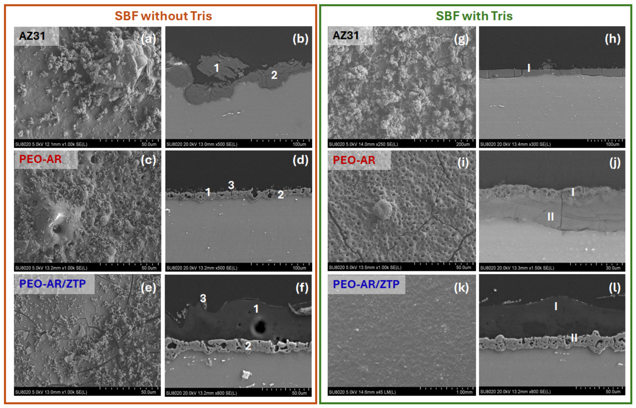
Figure 9 displays the morphological analyses of the three samples after two weeks of immersion SBF under two conditions: Figure 9a SBF without Tris and Figure 9b SBF with Tris, as well as the morphology of the corrosion following immersion, and establishes a correlation between the observed degradation characteristics and the electrochemical behaviour analyzed previously.
-
SBF without Tris
According to the medium without Tris (Figure 9a), the AZ31 has a highly corroded surface, characterized by extensive deposition of corrosion products. Cross-sectional images reveal deep corrosion penetration into the substrate (localized corrosion), accompanied by crack formation and delamination in these products, indicating severe degradation. EDS analysis at points 1 and 2 (Table 2) reveals appreciable amounts of magnesium (Mg), and oxygen (O), together with high percentages of calcium (Ca) and phosphorus (P) on the surface and more on the outer part of the sample. These elements are consistent with Ca-P-rich surface deposits (Ca:15.6 and P:11.9 at. %) and the formation of a combination of magnesium hydroxide (Mg(OH)2), magnesium carbonates (MgCO3) and magnesium phosphates (MgPO4). These species may be formed through dissolution of Mg and subsequent precipitation reactions involving carbonate and phosphate species from the medium. Despite their presence, these layers are loose and cracked, so they do not provide effective passivation. Their weak adhesion allows the electrolyte to continuously infiltrate, accelerating the corrosion process and leading to substantial degradation of the substrate. This behaviour is consistent with recent studies describing magnesium degradation as a dynamic process controlled by the interaction between local alkalisation, corrosion product precipitation and the stability of the resulting degradation layer. Although Mg(OH)2, carbonate- and phosphate-containing products can temporarily reduce corrosion kinetics, their protective efficiency strongly depends on their morphology, compactness and adhesion to the substrate. Once cracking and delamination occur, the degradation layer becomes less effective as a barrier, facilitating electrolyte transport and promoting further corrosion propagation [61,62].
In the case of the PEO-AR sample, the layer is well adhered to the substrate surface. In addition, precipitates rich in Ca, P, and Mg are observed on the surface and within the pores of the PEO (Ca: 12.4, P: 11.1, and Mg: 7.7 at.%, Table 2). This is attributed to local saturation and high pH (~ 9.2, as observed in Figure 8c) at the oxide–electrolyte interface—conditions favourable for calcium phosphate precipitation. Despite these surface deposits, cross-sectional analysis reveals that the underlying PEO coatings remain intact, with no evidence of corrosion beneath the oxide layer or electrolyte penetration hydrating the PEO layer. The PEO coating retains its typical porous and compact morphology, with a well-defined oxide layer and non-corrosive interfaces with the substrate. EDS analysis on the cross-sections (points 1 and 2, Table 2) shows that there is low incorporation of Ca and P within the oxide layer (point 2 in Table 2, 0.8 and 1.1 at.%, respectively) compared to the surface (point PV in Table 2, 12.4 and 11.1 at.%). This indicates that the observed deposits are mostly surface precipitates and not degradation products or the result of internal diffusion. Therefore, the deposited products on the surface, and possibly within the pores, may contribute to partially reducing electrolyte penetration. This is consistent with the high Router and Rinner values during all the EIS tests (Table 1), and with the large area of the surface remaining intact in Figure 8a.
The sample PEO-AR/ZTP retained some of its structural integrity after two weeks of immersion, as it uniformly covered the PEO coating. In addition, a surface layer of deposited products is observed on the sol-gel layer. This layer is composed of a high percentage of P, Ca, Si, and Zr (7.1, 9.5, 9.3, and 0.8 at.%, respectively, Figure 9e and Table 2 in the plan view), suggesting that increasing the pH of the medium, until 8.6 (Figure 8d), led to the precipitation of mixed calcium and phosphate compounds. EDS analysis revealed that the Ca/P ratio is 1.3 for these deposits, possible with the formation of Ca-P-containing surface deposits observed during magnesium degradation. This Ca-P deposition is comparable to that described by Liu et al. In the case of calcium metaphosphate coatings on magnesium alloys, similar Ca/P ratios and morphologies were observed after exposure to SBF [70]. Furthermore, in Figure 9f, the sol-gel coating remains well adhered to the PEO, with no delamination at the interface, but it does appear slightly degraded due to the reduced thickness of the sol-gel. Additionally, the deposited layer observed in Figure 9e is also visible in the cross-section and appears to be a secondary deposition layer, resulting from the ion exchange and precipitation processes that occur during immersion. This agrees with the higher impedance response and the elevated fitted resistance values measured during the immersion period (Figure 4b,c and Table 1).
-
SBF with Tris
In contrast, the samples in the SBF with Tris demonstrate different degradation performance compared to SBF without Tris. In the case of the AZ31 (Figure 9g,h), although the surface still appears to be covered by corrosion products (Figure 9g), the cross-sectional image reveals more uniform corrosion (Figure 9h) with damage spread across the entire surface of the substrate compared to the sample in SBF without Tris (Figure 9b). In addition, the corrosion layer appears less dense and more cracked. Furthermore, EDS analysis shows the presence of Mg and O (21.1 and 46.9 at.%), but significantly lower levels of Ca and P (8.0 and 8.8 at.%) compared to the SBF without Tris (20.6, 46.4, 15.6 and 11.9 at.%, respectively). This suggests that Tris limits the formation and stability of protective corrosion products, particularly Mg(OH)2, thereby hindering the development of a stable protective layer and leaving the surface more susceptible to continuous electrolyte attack.
The PEO-AR in Figure 9i shows clear signs of degradation, as the PEO layer appears cracked and there is localized deposition of products on the surface. The cross-section (Figure 9j) shows partial degradation of the PEO coating with the presence of corrosion products beneath the PEO layer. EDS analysis reveals high concentrations of Mg, Ca, P, and Cl both within (1.2, 0.1, 14.2 and 2.2 at.%) and beneath the oxide layer (14.0, 0.8, 2.8 and 0.3 at.%). This is consistent with the EIS results, where Rinner decays abruptly after 24 h of immersion and the substrate starts to corrode easily. These findings indicate that Tris facilitates the infiltration of electrolytes into the coating, possibly through microcracks or defects, and promotes the dissolution of previously formed corrosion products. Although the oxide layers remain attached to the substrate, their protective effect is compromised due to underlying corrosion (~10 μm of thickness) and delamination of the coating. Interestingly, despite the observable degradation, the levels of Mg and O in the corrosion product layer are slightly lower (14.0 and 58.6 at.%) than those in the condition without Tris (where there is not formation of corrosion products under PEO coating). These observations suggest that Tris limits the accumulation of Mg(OH)2, but at the cost of leaving the surface more vulnerable to continuous ionic attack, which is corroborated by the low values of Router and Rinner with immersion time (Table 1).
In the PEO-AR/ZTP system, the coating retains most of its structural integrity. Figure 9k shows that the surface is completely flat with no apparent presence of deposited products, as is the case with samples in SBF without Tris. Analyzing the surface using EDS, the surface is dominated by Si, Zr and O (17.2, 0.2, and 41.7 at.%), with no deposition of Ca or P (Table 2, no Ca detected and 1.5 at.% of P). This confirms that the buffer prevents the local alkalisation necessary for the precipitation of phosphate- and calcium-rich compounds (Figure 9d). Consequently, this layer that is observed in the absence of Tris does not form. Furthermore, the morphological integrity of the sol-gel coating is largely maintained during the immersion period, and Figure 9l shows that the layer is continuous, well adhered, and that the PEO coating shows no signs of hydration. Only slight delamination is observed at the PEO/sol-gel interface, which could be related to the handling of the sample during resin embedding rather than to actual degradation. Overall, the sol-gel coating preserves its morphology and adhesion considerably better than the unsealed PEO coating during the investigated immersion period. This agrees with the EIS results, where Rmix and Rinner, remain consistently higher than those of the unsealed PEO coating (Figure 6d).
The combined evidence from EIS, immersion tests and post-immersion morphology reveal three fundamentally different corrosion mechanisms for AZ31, PEO-AR and PEO-AR/ZTP in SBF with and without Tris.
For the AZ31, corrosion in SBF proceeds through rapid dissolution of Mg accompanied by local alkalisation at the metal/electrolyte interface, leading to the precipitation of Mg(OH)2, Mg-carbonates and Ca-P deposits. Although these products accumulate extensively, they form a highly cracked and poorly adherent layer that is easily disrupted by continued corrosion, allowing electrolyte infiltration and continued corrosion propagation. When Tris is added, the degradation pathway changes substantially. By influencing Mg+2 speciation, reducing the stability of Mg(OH)2, and modifying the local precipitation equilibria, Tris hinders the development of protective Mg(OH)2 and Ca-P-containing corrosion products. Consequently, the surface does not benefit from any protective precipitation, the corrosion layer remains thin and fragile, and the attack becomes more uniformly distributed across the substrate, resulting in faster overall degradation.
The PEO-AR coating exhibits a markedly different mechanism. In SBF without Tris, the compact inner barrier of the PEO oxide remains intact, and precipitation of Ca-P species within the pores-favoured by the high local pH created at the oxide/solution interface enhances blockage of corrosion pathways, maintaining comparatively high Router and Rinner resistances during immersion. However, this beneficial pore sealing does not occur in SBF with Tris. The buffering action suppresses alkalisation, preventing Ca-P deposition, while simultaneously promoting dissolution of corrosion products and facilitating electrolyte penetration through PEO porosity and microcracks. As infiltration progresses, under film corrosion initiates beneath the oxide, degrading the compact layer and causing a sharp drop in electrochemical resistance. Ultimately, the PEO retains some structural attachment to the substrate, but its barrier effect progressively decreases in the presence of Tris.
The duplex PEO-AR/ZTP system follows a more robust and stable pathway. In SBF without Tris, the sol-gel coating completely seals the porosity of the PEO whilst precipitating a secondary surface layer rich in Ca-P, which further contributes to blocking the pores and reinforcing the barrier. The coating remains dense and adherent, with minimal thickness changes and no signs of electrolyte penetration. Even in SBF with Tris, where Ca-P-phases precipitation is suppressed, the sol-gel layer preserves its continuity and chemical stability. All this is confirmed in EIS where both the sol-gel and the underlying PEO maintain high resistance values compared to the unsealed PEO coating throughout immersion despite their progressive evolution with exposure time. Only interfacial changes are observed, probably caused by sample handling rather than actual degradation. Overall, these observations indicate that the sol-gel layer acts as a chemically resistant and diffusion-limiting barrier that mitigates the destabilizing influence of Tris and delays electrolyte penetration and degradation of the underlying PEO layer during the investigated immersion period.
All these observations indicate that the corrosion behaviour of all the coated systems is governed by the interplay between pH-driven precipitation, electrolyte ingress and film stability. Tris seems to hinder protective film formation and to accelerate corrosion in the AZ31 and PEO-coated samples, while the sol-gel sealing mitigates this effect. The PEO-AR/ZTP duplex system therefore appears to offer the most effective preservation of structural integrity and electrochemical performance over the immersion period evaluated, in both SBF without Tris and SBF with Tris.

4. Conclusions

The results clearly demonstrate how the corrosion mechanisms and protective effectiveness of each system are strongly dependent on whether the medium stabilizes or suppresses the formation of corrosion and Ca-P products.
In SBF without Tris, where local alkalisation enables the precipitation of Mg(OH)2, MgCO3 and Ca-P-rich compounds, the bare AZ31 forms thick but unstable layers that crack and delaminate, offering minimal protection. The PEO-AR coating benefits from Ca-P precipitation on the surface and inside the porous structure, which slows down electrolyte ingress and preserves the barrier layer for a longer time. The duplex PEO-AR/ZTP system shows the best corrosion behaviour in this medium, forming a dense Ca-P layer on top of the sol-gel, while maintaining full adhesion and structural integrity.
A completely different scenario emerges in SBF with Tris, where Tris suppresses local pH increases, prevents Ca-P precipitation, interferes with Mg(OH)2 stability, and accelerates continuous dissolution. Under these conditions, AZ31 rapidly loses the protective effect of its corrosion products. The PEO-AR coating exhibits a marked reduction in protective performance: Tris promotes electrolyte penetration into the porous PEO network, dissolves surface precipitates and activates corrosion beneath the coating, leading to partial detachment and barrier failure. The PEO-AR/ZTP system retains higher protective performance even in this aggressive environment. The sol-gel sealing prevents Tris from accessing the pore network, inhibits the formation of adsorbed intermediates and maintains a largely continuous and adherent protective layer throughout the investigated immersion period.
Overall, the comparison between SBF with Tris and without Tris highlights that coatings evaluated solely in standard SBF may overestimate the intrinsic corrosion resistance because protective Ca-P deposits partially mask degradation processes. The SBF with Tris medium, by suppressing these precipitates, provides a more stringent assessment of each system when passive film formation is hindered. Within this framework, the present work demonstrates that the ZTP-sealed PEO system provides the highest corrosion resistance among the evaluated systems during the investigated immersion period. This confirms the critical role of sol-gel sealing in stabilizing PEO layers, maintaining barrier continuity and reducing electrolyte penetration under conditions that challenge surface chemistry and coating integrity. From a coating-development perspective, these findings support sol-gel post-sealing as an effective strategy to improve the corrosion resistance of PEO-coated Mg alloys under aggressive testing conditions. Further quantitative degradation analyses—including mass loss, hydrogen evolution and corrosion-depth measurements—would be required to fully characterize the degradation behaviour of this coating system over extended immersion periods.

Supplementary Materials

The following supporting information can be downloaded at https://www.mdpi.com/article/10.3390/coatings16080938/s1. Figure S1: (a,d) Nyquist and (b,c,e,f) Bode diagrams obtained for AZ31 after 2, 24, 72 and 168 h in (a–c) SBF without Tris and (d–f) SBF with Tris at 37 °C. Unfilled: SBF without Tris and filled: SBF with Tris; Figure S2: The evolution of n of AZ31, PEO-AR and PEO-AR/ZTP samples at 2, 24, 48, 72, 96 h and 1 week in SBF without Tris and SBF with Tris. The n value of the (a,c) outer vs. inner parts, and (c,d) inner/mix vs. charge transfer/inner parts. Black-square: AZ31 alloy, Red-circle: PEO-AR and Blue-triangle: PEO-AR/ZTP systems. Unfilled: SBF without Tris and filled: SBF with Tris; Figure S3: (a,d) Nyquist and (b,c,e,f) Bode diagrams obtained for PEO-AR coating after 2, 24, 72 and 168 h in SBF (a–c) SBF without Tris and (d–f) SBF with Tris at 37 °C. Unfilled: SBF without Tris and filled: SBF with Tris.

Author Contributions

Conceptualization, L.M. and M.-G.O.; methodology, L.M. and M.-G.O.; validation, Y.P. and M.-G.O.; formal analysis, L.M.; investigation, L.M. and Y.P.; writing—original draft preparation, L.M.; writing—review and editing, M.-G.O.; supervision, M.-G.O.; funding acquisition, L.M. and M.-G.O. All authors have read and agreed to the published version of the manuscript.

Funding

This research was funded by the Fédération Wallonie-Bruxelles (Belgium) through the University of Mons (UMONS). Lara Moreno received funding from the Come2Wallonia (C2W) fellowship programme, co-funded by the European Union’s Horizon 2020 research and innovation programme under the Marie Skłodowska-Curie grant agreement No. 101034383.

Institutional Review Board Statement

Not applicable.

Informed Consent Statement

Not applicable.

Data Availability Statement

The data presented in this study are available from the corresponding author upon reasonable request.

Conflicts of Interest

The authors declare no conflicts of interest.

References

  1. Niranjan, C.A.; Raghavendra, T.; Rao, M.P.; Siddaraju, C.; Gupta, M.; Jain, V.K.S.; Aishwarya, R. Magnesium Alloys as Extremely Promising Alternatives for Temporary Orthopedic Implants—A Review. J. Magnes. Alloys 2023, 11, 2688–2718. [Google Scholar] [CrossRef]
  2. May, H.; Alper Kati, Y.; Gumussuyu, G.; Yunus Emre, T.; Unal, M.; Kose, O. Bioabsorbable Magnesium Screw versus Conventional Titanium Screw Fixation for Medial Malleolar Fractures. J. Orthop. Traumatol. 2020, 21, 9. [Google Scholar] [CrossRef] [PubMed]
  3. Staiger, M.P.; Pietak, A.M.; Huadmai, J.; Dias, G. Magnesium and Its Alloys as Orthopedic Biomaterials: A Review. Biomaterials 2006, 27, 1728–1734. [Google Scholar] [CrossRef] [PubMed]
  4. Bosshardt, D.D.; Chappuis, V.; Buser, D. Osseointegration of Titanium, Titanium Alloy and Zirconia Dental Implants: Current Knowledge and Open Questions. Periodontol 2000 2017, 73, 22–40. [Google Scholar] [CrossRef] [PubMed]
  5. Zhao, H.; Cheng, J.; Zhao, C.; Wen, M.; Wang, R.; Wu, D.; Wu, Z.; Yang, F.; Sheng, L. The Recent Developments of Thermomechanical Processing for Biomedical Mg Alloys and Their Clinical Applications. Materials 2025, 18, 1718. [Google Scholar] [CrossRef] [PubMed]
  6. Jayasathyakawin, S.; Ravichandran, M.; Naveenkumar, R.; Radhika, N.; Ismail, S.O.; Mohanavel, V. Recent Advances in Magnesium Alloys for Biomedical Applications: A Review. Mater. Today Commun. 2025, 42, 111239. [Google Scholar] [CrossRef]
  7. Zhang, J.; Zhang, B.; Zhang, J.; Lin, W.; Zhang, S. Magnesium Promotes the Regeneration of the Peripheral Nerve. Front. Cell Dev. Biol. 2021, 9, 717854. [Google Scholar] [CrossRef] [PubMed]
  8. Hanawa, T. Metals and Medicine. Mater. Trans. 2021, 62, 139–148. [Google Scholar] [CrossRef]
  9. Ahmad Agha, N.; Feyerabend, F.; Mihailova, B.; Heidrich, S.; Willumeit, R. Magnesium Corrosion under Physiological Conditions. Eur. Cells Mater. 2014, 28, 22. [Google Scholar]
  10. Simchen, F.; Sieber, M.; Kopp, A.; Lampke, T. Introduction to Plasma Electrolytic Oxidation—An Overview of the Process and Applications. Coatings 2020, 10, 628. [Google Scholar] [CrossRef]
  11. Li, Z.; Wang, Y.; Wang, B.; Yuan, M.; Xun, M.; Zhang, H. Progress in the Study of Micro-Arc Oxidation Film Layers on Biomedical Metal Surfaces. Corros. Rev. 2025, 43, 175–187. [Google Scholar] [CrossRef]
  12. Mora-Sanchez, H.; del Olmo, R.; Rams, J.; Torres, B.; Mohedano, M.; Matykina, E.; Arrabal, R. Hard Anodizing and Plasma Electrolytic Oxidation of an Additively Manufactured Al-Si Alloy. Surf. Coat. Technol. 2021, 420, 127339. [Google Scholar] [CrossRef]
  13. Rojaee, R.; Fathi, M.; Raeissi, K.; Sharifnabi, A. Biodegradation Assessment of Nanostructured Fluoridated Hydroxyapatite Coatings on Biomedical Grade Magnesium Alloy. Ceram. Int. 2014, 40, 15149–15158. [Google Scholar] [CrossRef]
  14. M.Rúa, J.; Zuleta, A.A.; Ramírez, J.; Fernández-Morales, P. Micro-Arc Oxidation Coating on Porous Magnesium Foam and Its Potential Biomedical Applications. Surf. Coat. Technol. 2019, 360, 213–221. [Google Scholar] [CrossRef]
  15. Shen, X.; Hu, W.; Ping, L.; Liu, C.; Yao, L.; Deng, Z.; Wu, G. Antibacterial and Osteogenic Functionalization of Titanium with Silicon/Copper-Doped High-Energy Shot Peening-Assisted Micro-Arc Oxidation Technique. Front. Bioeng. Biotechnol. 2020, 8, 573464. [Google Scholar] [CrossRef] [PubMed]
  16. Tang, H.; Tao, W.; Wang, C.; Yu, H. Fabrication of Hydroxyapatite Coatings on AZ31 Mg Alloy by Micro-Arc Oxidation Coupled with Sol-gel Treatment. RSC Adv. 2018, 8, 12368–12375. [Google Scholar] [CrossRef] [PubMed]
  17. McCarroll, A.G.; Menezes, P.L. Modern Innovations and Applications in Plasma Electrolytic Oxidation Coatings on Aluminum, Magnesium, and Titanium. Coatings 2025, 15, 592. [Google Scholar] [CrossRef]
  18. Rahmati, M.; Saidi, R.; Raeissi, K.; Hakimizad, A. Effect of CaO Additive on the Properties of Plasma Electrolytic Oxidation Coatings on AZ31 Mg Alloy. J. Mater. Eng. Perform. 2024, 34, 1050–1066. [Google Scholar] [CrossRef]
  19. Rahmati, M.; Raeissi, K.; Toroghinejad, M.R.; Hakimizad, A.; Santamaria, M. Corrosion and Wear Resistance of Coatings Produced on AZ31 Mg Alloy by Plasma Electrolytic Oxidation in Silicate-Based K2TiF6 Containing Solution: Effect of Waveform. J. Magnes. Alloys 2022, 10, 2574–2587. [Google Scholar] [CrossRef]
  20. Castro, Y.; Durán, A. Control of Degradation Rate of Mg Alloys Using Silica Sol-gel Coatings for Biodegradable Implant Materials. J. Sol-Gel Sci. Technol. 2019, 90, 198–208. [Google Scholar] [CrossRef]
  21. Durán, K.S.; Hernández, N.; Rueda, L.M.; Hernández-Barrios, C.A.; Coy, A.E.; Viejo, F. Design of Multilayer Hybrid Sol-Gel Coatings with Bifunctional Barrier-Bioactive Response on the Elektron 21 Magnesium Alloy for Biomedical Applications. J. Magnes. Alloys 2021, 9, 2097–2112. [Google Scholar] [CrossRef]
  22. Toorani, M.; Aliofkhazraei, M. Review of Electrochemical Properties of Hybrid Coating Systems on Mg with Plasma Electrolytic Oxidation Process as Pretreatment. Surf. Interfaces 2019, 14, 262–295. [Google Scholar] [CrossRef]
  23. Chu, C.L.; Han, X.; Xue, F.; Bai, J.; Chu, P.K. Effects of Sealing Treatment on Corrosion Resistance and Degradation Behavior of Micro-Arc Oxidized Magnesium Alloy Wires. Appl. Surf. Sci. 2013, 271, 271–275. [Google Scholar] [CrossRef]
  24. Ahmadipour, M.; Mohammadi, H.; Pang, A.L.; Arjmand, M.; Otitoju, T.A.; Okoye, P.U.; Rajitha, B. A Review: Silicate Ceramic-Polymer Composite Scaffold for Bone Tissue Engineering. Int. J. Polym. Mater. Polym. Biomater. 2022, 71, 180–195. [Google Scholar] [CrossRef]
  25. Ren, L.; Tsuru, K.; Hayakawa, S.; Osaka, A. Novel Approach to Fabricate Porous Gelatin–Siloxane Hybrids for Bone Tissue Engineering. Biomaterials 2002, 23, 4765–4773. [Google Scholar] [CrossRef] [PubMed]
  26. Akbarzadeh, S.; Paint, Y.; Olivier, M.-G. A Comparative Study of Different Sol-Gel Coatings for Sealing the Plasma Electrolytic Oxidation (PEO) Layer on AA2024 Alloy. Electrochim. Acta 2023, 443, 141930. [Google Scholar] [CrossRef]
  27. Merino, E.; El Tawil, M.; Sobrados, I.; Durán, A.; Castro, Y. In-Vitro Degradation Behavior of Hybrid Epoxy-Alkyl Sol-gel/Anodized Composite Coating on AZ31B Mg Alloy. J. Sol-Gel Sci. Technol. 2025, 114, 139–147. [Google Scholar] [CrossRef]
  28. Liu, Y.; Cheng, X.; Wang, X.; Sun, Q.; Wang, C.; Di, P.; Lin, Y. Micro-Arc Oxidation-Assisted Sol-Gel Preparation of Calcium Metaphosphate Coatings on Magnesium Alloys for Bone Repair. Mater. Sci. Eng. C 2021, 131, 112491. [Google Scholar] [CrossRef] [PubMed]
  29. Pezzato, L.; Rigon, M.; Martucci, A.; Brunelli, K.; Dabalà, M. Plasma Electrolytic Oxidation (PEO) as Pre-Treatment for Sol-Gel Coating on Aluminum and Magnesium Alloys. Surf. Coat. Technol. 2019, 366, 114–123. [Google Scholar] [CrossRef]
  30. Gobara, M.; Naeem, I.; Sheashea, M.; Correa-Duarte, M.A.; Elbasuney, S. Eu-Substituted Hydroxyapatite/Silica Sol-Gel Treatment for Corrosion Protection of AZ31 Magnesium Alloy. Ceram. Int. 2024, 50, 32051–32063. [Google Scholar] [CrossRef]
  31. Ivanou, D.K.; Yasakau, K.A.; Kallip, S.; Lisenkov, A.D.; Starykevich, M.; Lamaka, S.V.; Ferreira, M.G.S.; Zheludkevich, M.L. Active Corrosion Protection Coating for a ZE41 Magnesium Alloy Created by Combining PEO and Sol-gel Techniques. RSC Adv. 2016, 6, 12553–12560. [Google Scholar] [CrossRef]
  32. Fernández-Hernán, J.P.; López, A.J.; Torres, B.; Martínez-Campos, E.; Matykina, E.; Rams, J. Anticorrosion and Cytocompatibility Assessment of Graphene-Doped Hybrid Silica and Plasma Electrolytic Oxidation Coatings for Biomedical Applications. ACS Biomater. Sci. Eng. 2021, 7, 5861–5877. [Google Scholar] [CrossRef] [PubMed]
  33. Ibrahim, H.; Dehghanghadikolaei, A.; Advincula, R.; Dean, D.; Luo, A.; Elahinia, M. Ceramic Coating for Delayed Degradation of Mg-1.2Zn-0.5Ca-0.5Mn Bone Fixation and Instrumentation. Thin Solid Film. 2019, 687, 137456. [Google Scholar] [CrossRef]
  34. Merino, E.; Durán, A.; Castro, Y. Integrated Corrosion-Resistant System for AZ31B Mg Alloy via Plasma Electrolytic Oxidation (PEO) and Sol-Gel Processes. Int. J. Appl. Glass Sci. 2021, 12, 519–530. [Google Scholar] [CrossRef]
  35. Chen, Y.; Lu, X.; Lamaka, S.V.; Ju, P.; Blawert, C.; Zhang, T.; Wang, F.; Zheludkevich, M.L. Active Protection of Mg Alloy by Composite PEO Coating Loaded with Corrosion Inhibitors. Appl. Surf. Sci. 2020, 504, 144462. [Google Scholar] [CrossRef]
  36. Moreno, L.; Mégret, A.; Paint, Y.; Olivier, M.-G. Influence of PEO Regime on Sol-Gel Infiltration and Performance of Hybrid Organic-Inorganic Coatings on AZ31 Alloy. J. Mater. Res. Technol. 2026, 42, 3367–3375. [Google Scholar] [CrossRef]
  37. Yang, Z.; Wang, Z.; Li, J.; Ding, S.; Yi, S. Tribological and Machining Performance of Novel DE@Mo2CTx MXene Bio-Microcapsule Nanofluids in Machining of Magnesium Alloys. Tribol. Int. 2025, 211, 110828. [Google Scholar] [CrossRef]
  38. Maurice, V.; Marcus, P. Progress in Corrosion Science at Atomic and Nanometric Scales. Prog. Mater. Sci. 2018, 95, 132–171. [Google Scholar] [CrossRef]
  39. Negahban, A.; Shamsi, M.; Sedighi, M. Advances in the Modification of Magnesium-Based Biomaterials to Address Corrosion and Corrosion-Fatigue: A Review of Developments and Prospects. J. Mater. Res. Technol. 2024, 30, 4064–4108. [Google Scholar] [CrossRef]
  40. Xu, L.; Liu, X.; Sun, K.; Fu, R.; Wang, G. Corrosion Behavior in Magnesium-Based Alloys for Biomedical Applications. Materials 2022, 15, 2613. [Google Scholar] [CrossRef] [PubMed]
  41. Shadanbaz, S.; Dias, G.J. Calcium Phosphate Coatings on Magnesium Alloys for Biomedical Applications: A Review. Acta Biomater. 2012, 8, 20–30. [Google Scholar] [CrossRef] [PubMed]
  42. McFerran, A.; McIlhatton, E.; McGuckin, E.; Byrne, M.; Diamond, O.J.; Napier, R.J.; O’Connor, J.; Lemoine, P.; Boyd, A.R.; Ward, J.; et al. Calcium Phosphate and Ion-Substituted Coatings for Resorbable Magnesium-Based Bone Implants: A Review. J. Magnes. Alloys 2025, 16, 101935. [Google Scholar] [CrossRef]
  43. Sheikh, Z.; Abdallah, M.-N.; Hanafi, A.A.; Misbahuddin, S.; Rashid, H.; Glogauer, M. Mechanisms of in Vivo Degradation and Resorption of Calcium Phosphate Based Biomaterials. Materials 2015, 8, 7913–7925. [Google Scholar] [CrossRef] [PubMed]
  44. Xin, Y.; Hu, T.; Chu, P.K. Influence of Test Solutions on In Vitro Studies of Biomedical Magnesium Alloys. J. Electrochem. Soc. 2010, 157, C238. [Google Scholar] [CrossRef]
  45. Yavuzyegit, B.; Karali, A.; De Mori, A.; Smith, N.; Usov, S.; Shashkov, P.; Bonithon, R.; Blunn, G. Evaluation of Corrosion Performance of AZ31 Mg Alloy in Physiological and Highly Corrosive Solutions. ACS Appl. Bio Mater. 2024, 7, 1735–1747. [Google Scholar] [CrossRef] [PubMed]
  46. Cui, L.-Y.; Hu, Y.; Zeng, R.; Yongxin, Y.; Sun, D.-D.; Li, S.; Zhang, F.; Han, E.-H. New Insights into the Effect of Tris-HCl and Tris on Corrosion of Magnesium Alloy in Presence of Bicarbonate, Sulfate, Hydrogen Phosphate and Dihydrogen Phosphate Ions. J. Mater. Sci. Technol. 2017, 33, 971–986. [Google Scholar] [CrossRef]
  47. Guo, Y.; Sun, M.; Zhang, W.; Wang, L. Machine Learning in Enhancing Corrosion Resistance of Magnesium Alloys: A Comprehensive Review. Metals 2023, 13, 1790. [Google Scholar] [CrossRef]
  48. Mei, D.; Lamaka, S.V.; Lu, X.; Zheludkevich, M.L. Selecting Medium for Corrosion Testing of Bioabsorbable Magnesium and Other Metals—A Critical Review. Corros. Sci. 2020, 171, 108722. [Google Scholar] [CrossRef]
  49. Yang, J.; Zhang, Z.; Yao, W.; Wu, Y.; Gao, Y.; Yang, Y.; Wu, L.; Serdechnova, M.; Blawert, C.; Pan, F. Recent Developments in Coatings on Biodegradable Mg Alloys: A Review. J. Magnes. Alloys 2025, 13, 1405–1427. [Google Scholar] [CrossRef]
  50. Moreno, L.; Mégret, A.; Paint, Y.; Gonon, M.; Vitry, V.; Olivier, M.-G. Comparison of Spark and Soft Regimes in the PEO Process in Terms of Corrosion and Wear Performance of AZ31 Alloy for Biomedical Applications. Mater. Today Commun. 2025, 42, 111440. [Google Scholar] [CrossRef]
  51. Rodič, P.; Iskra, J.; Milošev, I. A Hybrid Organic-Inorganic Sol-Gel Coating for Protecting Aluminium Alloy 7075-T6 against Corrosion in Harrison’s Solution. J. Sol-Gel. Sci. Technol. 2014, 70, 90–103. [Google Scholar] [CrossRef]
  52. Nguyen, T.T.; Thai, T.T.; Paint, Y.; Trinh, A.T.; Olivier, M.-G. Effect of Cerium Nitrate Concentration on Corrosion Protection of Hybrid Organic/Inorganic Si/Zr Sol-Gel Coating Applied on Hot-Dip Galvanized Steel. Surf. Coat. Technol. 2024, 480, 130562. [Google Scholar] [CrossRef]
  53. Xiong, Y.; Zhang, A. Corrosion Behavior of AZ80 Magnesium Alloy in Simulated Static and Dynamic Fluid Environments with Different pH Values. J. Mater. Eng. Perform. 2023, 32, 6915–6929. [Google Scholar] [CrossRef]
  54. Almajidi, Y.Q.; Ali, E.; Jameel, M.F.; Saleh, L.H.; Aggarwal, S.; Zearah, S.A.; Alamula, A.F.; Alsaalamy, A.; Sharifianjazi, F.; Bathaei, M.S. Unveiling the Effect of Particle Incorporation in PEO Coatings on the Corrosion and Wear Performance of Magnesium Implants. Lubricants 2023, 11, 519. [Google Scholar] [CrossRef]
  55. Akbarzadeh, S.; Klumpp, R.E.; Mégret, A.; Ölmez, V.; Vitry, V.; Olivier, M.-G. Breakthrough in Aluminum Protection: Electrochemical and Wear Insights into Sol-Gel Sealed PEO-Coated AA2024-T3 and AA2198-T851. Surf. Coat. Technol. 2024, 494, 131510. [Google Scholar] [CrossRef]
  56. Arthanari, S.; Shin, K.S.; Nallaiyan, R. Dynamic Electrochemical Impedance Spectroscopy (DEIS) Studies of AZ31 Magnesium Alloy in Simulated Body Fluid Solution. RSC Adv. 2014, 4, 27791–27795. [Google Scholar] [CrossRef]
  57. Pan, J.; Zhang, J.; Li, Y.; Yang, F.; Yu, Y.; Wang, S. Degradation Behavior of Medical MgZZC-1 in Various Simulated Body Fluids. Langmuir 2024, 40, 4674–14684. [Google Scholar] [CrossRef] [PubMed]
  58. Plekhova, N.G.; Novikova, P.A.; Chernenko, I.N.; Stepanyugina, A.K.; Shevchenko, O.V.; Marchenko, V.S.; Gnedenkov, A.S.; Sinebryukhov, S.L.; Gnedenkov, S.V.; Shumatov, V.B. Magnesium Alloy Composite Coatings: In Vitro Study of Cytotoxicity, Adhesion, Cellular Structure and Function. Russ. Open Med. J. 2025, 14, e0203. [Google Scholar] [CrossRef]
  59. Xue, F.; Zhu, D.; Wang, J.; Diao, Y.; Wenbin, H. Corrosion Resistance and Ion Exchange Properties of Montmorillonite Film on AZ31 in SBF Solution. Colloids Surf. A Physicochem. Eng. Asp. 2024, 691, 133911. [Google Scholar] [CrossRef]
  60. Hadavi, H.; Soltani, R.; Tamjid, E.; Aghdam, R. In Vitro Corrosion Behavior and Biological Properties of Magnesium- Zinc-Calcium Alloy Coated with Polycaprolactone Nanofibers. J. Ultrafine Grained Nanostruct. Mater. 2021, 54, 93–100. [Google Scholar] [CrossRef]
  61. Kovacevic, S.; Ali, W.; Mandal, T.K.; Martínez-Pañeda, E.; LLorca, J. Impact of pH and Chloride Content on the Biodegradation of Magnesium Alloys for Medical Implants: An in Vitro and Phase-Field Study. Acta Biomater. 2025, 198, 546–565. [Google Scholar] [CrossRef] [PubMed]
  62. Xin, Y.; Chu, P.K. Influence of Tris in Simulated Body Fluid on Degradation Behavior of Pure Magnesium. Mater. Chem. Phys. 2010, 124, 33–35. [Google Scholar] [CrossRef]
  63. Zeng, R.; Hu, Y.; Guan, S.-K.; Cui, H.-Z.; Han, E.-H. Corrosion of Magnesium Alloy AZ31: The Influence of Bicarbonate, Sulphate, Hydrogen Phosphate and Dihydrogen Phosphate Ions in Saline Solution. Corros. Sci. 2014, 86, 171–182. [Google Scholar] [CrossRef]
  64. Gray-Munro, J.; Strong, M. A Study on the Interfacial Chemistry of Magnesium Hydroxide Surfaces in Aqueous Phosphate Solutions: Influence of Ca2+, Cl− and Protein. J. Colloid Interface Sci. 2012, 393, 421–428. [Google Scholar] [CrossRef] [PubMed]
  65. Khalili, V.; Virtanen, S.; Boccaccini, A.R. Surface Treatment with Cell Culture Medium: A Biomimetic Approach to Enhance the Resistance to Biocorrosion in Mg and Mg-Based Alloys—A Review. J. Biomed. Mater. Res. Part B Appl. Biomater. 2025, 113, e35617. [Google Scholar] [CrossRef] [PubMed]
  66. Gonzalez, J.; Hou, R.Q.; Nidadavolu, E.P.S.; Willumeit-Römer, R.; Feyerabend, F. Magnesium Degradation under Physiological Conditions—Best Practice. Bioact. Mater. 2018, 3, 174–185. [Google Scholar] [CrossRef] [PubMed]
  67. Xin, Y.; Hu, T.; Chu, P.K. In Vitro Studies of Biomedical Magnesium Alloys in a Simulated Physiological Environment: A Review. Acta Biomater. 2011, 7, 1452–1459. [Google Scholar] [CrossRef] [PubMed]
  68. Zarur, M.; Seijo-Rabina, A.; Goyanes, A.; Concheiro, A.; Alvarez-Lorenzo, C. pH-Responsive Scaffolds for Tissue Regeneration: In Vivo Performance. Acta Biomater. 2023, 168, 22–41. [Google Scholar] [CrossRef] [PubMed]
  69. Galow, A.-M.; Rebl, A.; Koczan, D.; Bonk, S.M.; Baumann, W.; Gimsa, J. Increased Osteoblast Viability at Alkaline pH in Vitro Provides a New Perspective on Bone Regeneration. Biochem. Biophys. Rep. 2017, 10, 17–25. [Google Scholar] [CrossRef] [PubMed]
  70. Liu, C.; Ren, Z.; Xu, Y.; Pang, S.; Zhao, X.; Zhao, Y. Biodegradable Magnesium Alloys Developed as Bone Repair Materials: A Review. Available online: https://www.hindawi.com/journals/scanning/2018/9216314/ (accessed on 24 March 2020).
Figure 1. Preparation scheme for hybrid sol-gel coating on the PEO-coated sample.
Coatings 16 00938 g001
Figure 2. (a,c) Plan view and (b,d) cross-section of (a,b) PEO-AR and (c,d) PEO-AR/ZTP systems on AZ31 alloy. EDS elemental maps obtained from the cross-sectional samples of Figure 2 (b,d).
Coatings 16 00938 g002
Figure 3. Evaluation of the electrochemical impedance modulus at low frequencies at 2, 24, 48, 72, 96 h and 1 week for AZ31, PEO-AR and PEO-AR/ZTP systems in (a) SBF without Tris and (b) SBF with Tris at 37 °C. Black-square: AZ31 alloy, Red-circle: PEO-AR and Blue-triangle: PEO-AR/ZTP systems. Unfilled: SBF without Tris and filled: SBF with Tris. This graph shows the electrochemical impedance modulus values at low frequency for the two replicates.
Coatings 16 00938 g003
Figure 4. (a,d) Nyquist and (b,c,e,f) Bode diagrams obtained for AZ31, PEO-AR and PEO-AR/ZTP specimens after 2, 24, 72 and 168 h in (a–c) SBF without Tris and (d–f) SBF with Tris at 37 °C. Black-square: AZ31 alloy, Red-Circle: PEO-AR and Blue-Triangle: PEO-AR/ZTP. Unfilled: SBF without Tris and filled: SBF with Tris.
Coatings 16 00938 g004
Figure 5. Equivalent circuits used to fit the EIS data of Figure 4 for (A) AZ31, (B,C) PEO-AR and (D) PEO-AR/ZTP samples at 2, 24, 48, 72, 96 h and 1 week in SBF without Tris and SBF with Tris.
Coatings 16 00938 g005
Figure 6. The evolution of resistances of AZ31, PEO-AR and PEO-AR/ZTP samples at 2, 24, 48, 72, 96 h and 1 week in SBF without Tris and SBF with Tris. The resistance of the (a,c) outer vs. inner parts, and (b,d) inner/mix vs. charge transfer/inner parts. Black-square: AZ31 alloy, Red-circle: PEO-AR and Blue-triangle: PEO-AR/ZTP systems. Unfilled: SBF without Tris and filled: SBF with Tris.
Coatings 16 00938 g006
Figure 7. The evolution of CPE of AZ31, PEO-AR and PEO-AR/ZTP samples at 2, 24, 48, 72, 96 h and 1 week in SBF without Tris and SBF with Tris. The CPE of (a,c) outer vs. inner layers, and (b,d) inner/mix parts vs. charge transfer/inner parts. Black-square: AZ31 alloy, Red-circle: PEO-AR and Blue-triangle: PEO-AR/ZTP systems. Unfilled: SBF without Tris and filled: SBF with Tris.
Coatings 16 00938 g007
Figure 8. Immersion test in (a) SBF without Tris and (b) SBF with Tris at 6, 24, 72, 96 h and 1 and 2 weeks for AZ31, PEO-AR and PEO-AR/ZTP samples. (c,d) pH evolution during the immersion test for all the samples. The scale of Figure 8 (a,b) is 1.02 cm for all the samples.
Coatings 16 00938 g008
Figure 9. (a,c,e,g,i,k) Macrographs and (b,d,f,h,j,l) cross-section of (a,b,g,h) AZ31 alloy, (c,d,i,j) PEO-AR and (e,f,k,l) PEO-AR/ZTP samples after 2 weeks of immersion in (a–f) SBF without Tris and (g–l) SBF with Tris. The numbers inside of the pictures correspond to the EDS elemental analysis in at.% in those points.
Coatings 16 00938 g009
Table 1. Fitted values with the standard deviation from Figure 4 of AZ31, PEO-AR and PEO-AR/ZTP specimens after 2, 24, 48, 72, 96 h and 1 week of immersion in SBF without Tris and SBF with Tris.
Medium.SamplesType of CircuitTime
(h)
Rel ± SD
(Ω·cm2)
CPEdp+cp or CPEouter ± SD
(S·sn·cm−2)
n dp+cp or nouter ± SDR dp+cp or Router ± SD (Ω·cm2)CPEct, CPE inner or CPEmix ± SD
(S·sn·cm−2)
nct, ninner or nmix ± SDRinner or Rmix ± SD
(Ω·cm2)
CPEinner ± SD
(S·sn·cm−2)
ninner ± SDRinner ± SD
(Ω·cm2)
RL ± SD
(Ω·cm2)
L ± SD
(H·cm−2)
SBF without TrisAZ31A2114 ± 8.611.4 × 10−5 ± 3.3 × 10−60.72 ± 0.022.1 × 104 ± 4.9 × 1034.0 × 10−4 ± 9.2 × 10−50.98 ± 0.02----6.1 × 10³ ± 1.4 × 1034.1 × 103 ± 9.3 × 10²
2491.4 ± 3.73 6.4 × 10⁻⁶ ± 1.5 × 10−60.67 ± 0.025.0 × 102 ± 1.2 × 1025.1 × 10−6 ± 1.2 × 10−60.80 ± 0.02----1.2 × 10⁴ ± 1.4 × 1039.8 × 103 ± 2.2 × 10³
48118 ± 15.741.1 × 10−5 ± 2.6 × 10−60.62 ± 0.0145.7 × 102 ± 1.3 × 1026.3 × 10−6 ± 1.5 × 10−60.75 ± 0.02----7.1 × 10³ ± 1.6 × 1032.6 × 103 ± 5.9 × 10²
7286.3 ± 15.31 1.6 × 10⁻⁵ ± 3.7 × 10−60.76 ± 0.025.6 × 102 ± 1.3 × 1021.4 × 10−6 ± 3.3 × 10−70.89 ± 0.02----7.7 × 10³ ± 1.8 × 1037.7 × 102 ± 1.8 × 10²
96113 ± 6.946.4 × 10−6 ± 1.5 × 10−60.87 ± 0.015.1 × 102 ± 1.2 × 1023.1 × 10−6 ± 7.1 × 10−70.98 ± 0.02----2.6 × 10³ ±1.5 × 10⁴ ±
168139 ± 70.979.0 × 10−6 ± 2.1 × 10−60.62 ± 0.01 5.8 × 10² ± 1.3 × 1023.7 × 10−6 ± 8.5 × 10−70.90 ± 0.02----3.1 × 10³ ± 7.2 × 1025.1 × 103 ± 1.2 × 10³
PEO-ARB2124 ± 7.003.2 × 10−7 ± 5.0 × 10−80.78 ± 0.011.6 × 104 ± 4.8 × 1038.2 × 10−8 ± 4.5 × 10−80.86 ± 0.053.9 × 106 ± 5.7 × 10⁵-----
2483.8 ± 3.032.5 × 10−7 ± 1.1 × 10−70.76 ± 0.049.7 × 103 ± 3.1 × 1032.2 × 10−7 ± 1.0 × 10−70.84 ± 0.063.6 × 106 ± 1.8 × 10⁶-----
4830.6 ± 12.803.2 × 10−7 ± 2.2 × 10−70.62 ± 0.013.4 × 103 ± 5.5 × 1023.5 × 10−8 ± 1.2 × 10−80.92 ± 0.049.5 × 106 ± 5.9 × 10⁶-----
7220.0 ± 12.454.9 × 10−8 ± 1.2 × 10−80.74 ± 0.054.4 × 103 ± 1.0 × 1031.2 × 10−7 ± 7.9 × 10−80.79 ± 0.012.2 × 106 ± 9.7 × 10⁵-----
9620.0 ± 5.649.3 × 10−8 ± 5.4 × 10−80.71 ± 0.013.4 × 103 ± 6.2 × 1021.2 × 10−7 ± 3.8 × 10−80.78 ± 0.032.2 × 106 ± 4.3 × 10⁵-----
16882.0 ± 15.651.0 × 10−7 ± 6.4 × 10−80.78 ± 0.037.3 × 103 ± 3.7 × 1031.1 × 10−7 ± 2.1 × 10−80.85 ± 0.033.4 × 106 ± 3.2 × 10⁶-----
PEO-AR/ZTPD275.6 ± 9.837.5 × 10−8 ± 3.3 × 10−90.69 ± 0.025.3 × 103 ± 6.5 × 1021.0 × 10−7 ± 3.1 × 10−80.76 ± 0.023.7 × 106 ± 3.4 × 1061.0 × 10−7 ± 3.09 × 10−80.92 ± 0.012.4 × 107 ± 3.5 × 10⁶--
24181.0 ± 4.994.9 × 10−8 ± 3.4 × 10−90.77 ± 0.02 2.8 × 10³ ± 1.1 × 1031.1 × 10−7 ± 3.3 × 10−80.76 ± 0.021.1 × 106 ± 2.8 × 1051.2 × 10−7 ± 3.27 × 10−80.98 ± 0.012.6 × 107 ± 3.5 × 10⁶--
4820.0 ± 3.444.6 × 10−8 ± 2.3 × 10−80.75 ± 0.029.2 × 103 ± 1.9 × 1031.0 × 10−7 ± 2.4 × 10−80.75 ± 0.022.9 × 106 ± 3.4 × 1059.5 × 10−8 ± 2.38 × 10−80.90 ± 0.014.8 × 107 ± 1.8 × 10⁷--
7220.0 ± 5.665.2 × 10−8 ± 3.0 × 10−80.73 ± 0.048.3 × 103 ± 1.8 × 1031.0 × 10−7 ± 3.1 × 10−80.75 ± 0.022.5 × 106 ± 6.3 × 1051.0 × 10−7 ± 3.13 × 10−80.90 ± 0.011.2 × 107 ± 3.2 × 10⁶--
96184.0 ± 7.685.1 × 10−8 ± 2.1 × 10−80.77 ± 0.036.7 × 103 ± 7.7 × 1021.1 × 10−7 ± 2.1 × 10−80.76 ± 0.011.1 × 106 ± 1.5 × 1051.2 × 10−7 ± 2.08 × 10−80.90 ± 0.071.5 × 107 ± 8.4 × 10⁶--
16850.0 ± 6.53 3.6 × 10⁻⁸ ± 1.6 × 10−80.77 ± 0.029.8 × 103 ± 2.2 × 1031.6 × 10−7 ± 2.5 × 10−80.68 ± 0.024.1 × 106 ± 1.3 × 1061.5 × 10−7 ± 2.54 × 10−90.94 ± 0.021.7 × 107 ± 9.7 × 10⁶--
SBF with TrisAZ31A275.2 ± 17.39.0 × 10−5 ± 2.4 × 10−50.71 ± 0.069.2 × 101 ± 2.1 × 1013.1 × 10−6 ± 7.0 × 10−70.97 ± 0.02----3.6 × 10⁴ ± 8.3 × 1031.9 × 103 ± 4.3 × 10²
24107.0 ± 74.611.7 × 10−5 ± 3.9 × 10−60.71 ± 0.071.6 × 102 ± 3.6 × 1012.8 × 10−6 ± 6.5 × 10−70.98 ± 0.03----2.4 × 10³ ± 5.5 × 1021.3 × 103 ± 3.0 × 10²
48103.0 ± 11.452.3 × 10−5 ± 5.7 × 10−60.85 ± 0.021.3 × 102 ± 2.9 × 1019.6 × 10−6 ± 2.2 × 10−60.90 ± 0.03----2.2 × 10² ± 5.1 × 1011.6 × 103 ± 3.7 × 10²
7284.6 ± 19.462.4 × 10−5 ± 5.5 × 10−60.55 ± 0.044.7 × 101 ± 1.1 × 1011.3 × 10−5 ± 2.9 × 10−60.91 ± 0.01----1.7 × 10³ ± 4.0 × 1021.9 × 102 ± 4.3 × 101
9673.2 ± 5.581.9 × 10−5 ± 2.1 × 10−60.56 ± 0.014.2 × 101 ± 9.6 × 1001.9 × 10−5 ± 4.3 × 10−60.87 ± 0.07----4.2 × 10³ ± 9.6 × 1026.1 × 101 ± 1.4 × 101
168125 ± 24.581.5 × 10−5 ± 3.4 × 10−60.85 ± 0.073.8 × 101 ± 8.7 × 1006.4 × 10−6 ± 1.5 × 10−60.98 ± 0.03----6.2 × 10² ± 1.4 × 1021.5 × 103 ± 3.5 × 10²
PEO-ARB284.3 ± 1.424.2 × 10−6 ± 6.9 × 10−70.81 ± 0.022.8 × 102 ± 9.0 × 1015.9 × 10−7 ± 1.9 × 10−70.99 ± 0.031.5 × 104 ± 4.27 × 10²-----
2485.7 ± 5.722.7 × 10−6 ± 1.6 × 10−60.72 ± 0.072.2 × 102 ± 3.4 × 1013.5 × 10−6 ± 1.0 × 10−60.91 ± 0.031.32 × 104 ± 2.3 × 101-----
C4889.0 ± 8.269.9 × 10−6 ± 1.1 × 10−50.62 ± 0.082.4 × 102 ± 7.4 × 1014.5 × 10−6 ± 2.7 × 10−60.90 ± 0.085.15 × 103 ± 1.45 × 10²---1.2 × 10⁴ ± 1.2 × 1031.2 × 103 ± 1.5 × 10²
7273.6 ± 5.675.6 × 10−5 ± 4.70 × 10−50.49 ± 0.082.2 × 102 ± 7.1 × 1012.4 × 10−6 ± 2.1 × 10−60.98 ± 0.086.08 × 103 ± 9.6 × 101---3.0 × 10³ ± 1.0 × 1021.2 × 102 ± 1.8 × 101
9688.4 ± 6.732.7 × 10−6 ± 4.02 × 10−50.78 ± 0.011.3 × 102 ± 3.5 × 1015.7 × 10−6 ± 2.5 × 10−60.94 ± 0.052.15 × 103 ± 7.8 × 10²---3.3 × 10³ ± 1.45 × 1027.9 × 103 ± 1.05 × 10²
16878.2 ± 3.446.4 × 10−6 ± 4.08 × 10−60.68 ± 0.061.5 × 102 ± 2.0 × 1019.9 × 10−6 ± 4.98 × 10−60.87 ± 0.062.52 × 103 ± 2.45 × 10²---5.9 × 10³ ± 2.8 × 1033.7 × 102 ± 1.6 × 10²
PEO-AR/ZTPD2354.0 ± 35.684.5 × 10−8 ± 1.4 × 10−80.73 ± 0.011.6 × 104 ± 4.9 × 1037.4 × 10−8 ± 6.3 × 10−80.81 ± 0.033.1 × 105 ± 1.0 × 1057.7 × 10−7 ± 2.5 × 10−70.90 ± 0.033.0 × 108 ± 3.6 × 10⁷--
24109 ± 34.883.2 × 10−7 ± 1.0 × 10−70.62 ± 0.038.7 × 103 ± 2.8 × 1032.1 × 10−7 ± 6.8 × 10−80.65 ± 0.026.3 × 105 ± 2.0 × 1053.2 × 10−9 ± 1.0 × 10−90.90 ± 0.092.2 × 106 ± 7.1 × 10⁵--
48239 ± 200.27.7 × 10−8 ± 1.23 × 10−70.73 ± 0.019.2 × 103 ± 7.1 × 1031.1 × 10−7 ± 1.1 × 10−80.77 ± 0.094.7 × 105 ± 6.2 × 1042.1 × 10−7 ± 2.34 × 10−80.90 ± 0.049.8 × 106 ± 6.9 × 10⁶--
7274.5 ± 24.568.6 × 10−8 ± 3.20 × 10−80.68 ± 0.025.4 × 103 ± 9.7 × 1022.2 × 10−7 ± 2.74 × 10−80.79 ± 0.012.3 × 106 ± 6.99 × 1057.0 × 10−7 ± 1.4 × 10−70.90 ± 0.087.5 × 105 ± 2.1 × 10⁵--
96106 ± 39.147.0 × 10−8 ± 5.5 × 10−80.71 ± 0.013.1 × 103 ± 6.99 × 1022.6 × 10−7 ± 5.75 × 10−80.71 ± 0.019.9 × 105 ± 6.6 × 1054.5 × 10−6 ± 3.4 × 10−60.92 ± 0.034.0 × 105 ± 1.3 × 10⁵--
168325 ± 104.21.1 × 10−7 ± 4.2 × 10−80.76 ± 0.041.0 × 103 ± 1.4 × 1025.0 × 10−7 ± 3.0 × 10−70.86 ± 0.068.3 × 104 ± 2.6 × 1047.4 × 10−5 ± 2.4 × 10−50.98 ± 0.013.7 × 105 ± 6.4 × 10⁴--
Table 2. EDS analysis (at.%) and the standard deviation of them after two weeks of immersion in SBF without Tris and SBF with Tris for the different samples from Figure 9. PV: Plan view of Figure 9.
SampleMediumLocationCOFMgAlSiPClCaZnZrCa/P
AZ31SBF without TrisPV2.2 ± 0.246.4 ± 0.3-20.6 ± 0.92.3 ± 0.8-11.9 ± 0.9-15.6 ± 1.2--1.31
17.5 ± 0.566.2 ± 0.2-19.9 ± 0.81.9 ± 0.012.6 ± 0.80.8 ± 020.6 ± 0.010.3 ± 0.010.2 ± 0.01-0.38
28.8 ± 0.565.3 ± 0.1-21.2 ± 1.32.2 ± 0.010.9 ± 0.10.2 ± 0.010.7 ± 0.10.2 ± 0.030.4 ± 0.05-1.00
SBF with TrisPV3.4 ± 0.2446.9 ± 0.8-21.1 ± 1.23.9 ± 0.74.8 ± 0.88.8 ± 1.40.8 ± 0.18.0 ± 0.42.4 ± 0.2-0.91
I9.4 ± 1.261.5 ± 1.2-13.5 ± 0.24.2 ± 0.13.3 ± 0.74.6 ± 0.40.3 ± 0.012.4 ± 0.30.6 ± 0.01-0.52
PEO-ARSBF without TrisPV2.7 ± 0.362.8 ± 0.20.2 ± 0.017.7 ± 0.7 -1.1 ± 0.111.1 ± 2.1-12.4 ± 0.10.4 ± 0.01-1.26
17.5 ± 2.448.8 ± 0.12.3 ± 0.330.1 ± 1.11.1 ± 0.18.6 ± 1.40.3 ± 0.02 -0.5 ± 0.01 - -1.67
212.5 ± 1.758.1 ± 1.21.4 ± 0.214.2 ± 0.61.6 ± 0.19.7 ± 0.51.1 ± 0.40.1 ± 0.010.8 ± 0.010.3 ± 0.01-0.73
349.6 ± 1.941.2 ± 0.71.6 ± 0.4 - -3.1 ± 0.710.8 ± 0.1-3.6 ± 0.2--4.50
SBF with TrisPV7.6 ± 0.660.5 ± 0.70.7 ± 0.011.2 ± 0.17.5 ± 1.24.1 ± 1.214.2 ± 0.22.2 ± 0.10.1 ± 0.010.5 ± 0.01-0.01
I34.1 ± 0.841.7-5.2 ± 1.13.4 ± 0.112.2 ± 1.41.3 ± 0.20.3 ± 0.010.9 ± 0.01 --0.69
II13.0 ± 2.958.6 ± 0.8-14.0 ± 0.14.2 ± 0.75.4 ± 0.42.80.3 ± 0.010.8 ± 0.080.5 ± 0.2-0.29
PEO-AR/ZTPSBF without TrisPV8.7 ± 0.460.7 ± 1.2-2.6 ± 0.80.2 ± 0.019.3 ± 1.07.1 ± 0.1 0.6 ± 0.029.5 ± 0.10.6 ± 0.10.8 ± 0.021.33
167.0 ± 0.726.1 ± 0.7-0.6 ± 0.3 -5.3 ± 0.7- 0.6 ± 0.1 -- 0.4 ± 0.01-
28.7 ± 0.946.4 ± 0.43.9 ± 0.831.2 ± 1.21.0 ± 0.18.1 ± 0.9 -0.1 ± 0.01-0.3 ± 0.10.1 ± 0.01 -
342.7 ± 0.238.3 ± 0.21.9 ± 0.4 -0.8 ± 0.016.5 ± 0.80.4 ± 0.019.0 ± 0.4- - - -
SBF with TrisPV38.9 ± 1.241.7 ± 0.4 - 0.4 ± 0.01 0.3 ± 0.0117.2 ± 1.21.5---0.2 ± 0.02-
I66.5 ± 0.426.6 ± 0.8 -0.4 ± 0.01 -5.4 ± 1.7 -0.6 ± 0.2--0.5 ± 0.08-
II7.7 ± 0.747.4 ± 1.11.7 ± 0.331.7 ± 3.11.3 ± 0.019.4 ± 2.3 - - -- --
Disclaimer/Publisher’s Note: The statements, opinions and data contained in all publications are solely those of the individual author(s) and contributor(s) and not of MDPI and/or the editor(s). MDPI and/or the editor(s) disclaim responsibility for any injury to people or property resulting from any ideas, methods, instructions or products referred to in the content.