Article

Short-Term Overheating Damage Behavior of Thermal Barrier Coatings Under Uniform Temperature and Simulated Service Conditions

1
Tianmushan Laboratory, Hangzhou 311115, China
2
Research Institute of Aero-Engine, Beihang University, Beijing 100191, China
3
AECC Shenyang Liming Aero-Engine Co., Ltd., Shenyang 110043, China
4
School of Materials Science and Engineering, Beihang University, Beijing 100191, China
*
Author to whom correspondence should be addressed.
Coatings 2026, 16(8), 919; https://doi.org/10.3390/coatings16080919
Submission received: 15 June 2026 / Revised: 21 July 2026 / Accepted: 27 July 2026 / Published: 2 August 2026

Abstract

In this study, 8YSZ thermal barrier coatings (TBCs) were deposited on IC21 single-crystal superalloy substrates. Short-term overheating at 1300 °C was conducted for durations of 1, 5, and 10 min under both uniform temperature and simulated service conditions, followed by thermal cycling and thermal shock tests, respectively, to investigate the short-term overheating behavior of the coatings. The effects of short-term overheating on microstructural evolution and stress evolution under different conditions were analyzed, and the underlying damage mechanisms were determined. The results show that under uniform temperature conditions, short-term overheating drives the continuous growth of the thermally grown oxide (TGO). Coating failure occurs at the specimen edge, dominated by thermal stress concentration induced by geometric edge effects. The stress evolution is relatively mild, and the damage mechanism is primarily long-term interfacial degradation. Under simulated service conditions, short-term overheating induces sintering and cracking in the ceramic top coat. Coating failure occurs at the specimen center, dominated by crack coalescence. Transient temperature gradients generate high non-steady-state thermal stresses. The damage mechanism involves thermomechanical loading accelerating interfacial degradation, with synergistic effects of ceramic layer sintering and TGO destabilization, leading to a significant reduction in coating lifetime.

1. Introduction

Turbine blades are among the most critical hot-section components in aero-engines, and their reliable operation is essential for engine safety [1,2,3,4]. During service, the non-uniform distribution of high-temperature, high-velocity combustion gases from the combustor leads to varying cooling rates across different regions of turbine guide vanes, resulting in an uneven surface temperature field [5,6]. Under abnormal operating conditions such as combustor oil accumulation and ignition, poor fuel atomization, or sudden load surges caused by single-engine failure, localized short-term overheating may occur on the blades [4]. Once the actual service temperature exceeds the maximum allowable design temperature, overheating conditions arise [7,8,9]. Overheating poses a significant safety risk to aero-engine operation and has become one of the primary failure modes of turbine blades, directly accounting for 6.87% of blade failures [10,11,12,13].
6–8 wt.% Y2O3 partially stabilized zirconia (YSZ) coatings have become the most widely used thermal barrier coatings on aero-engine turbine blades due to their excellent overall performance. They exhibit well-recognized superior thermal stability and phase stability during long-term service at temperatures up to 1200 °C [14,15,16,17]. However, when the service temperature exceeds this upper limit, the microstructural evolution and damage behavior of YSZ coatings undergo significant changes, thereby accelerating coating degradation and even spallation failure. Numerous researchers have investigated the effects of overheating on coatings. Sun et al. [10] analyzed the high-temperature failure of a high-pressure turbine guide vane and found a crack approximately 7.1 mm in length penetrating three film cooling holes at the leading edge. The failure mechanism was attributed to the reduction in film hole diameter after TBC deposition, combined with blockage by oxide deposits, leading to reduced cooling airflow, localized overheating, and ultimately substrate property degradation and cracking. Kim et al. [18] reported that the type of thermal test significantly affects TBC lifetime. Increasing the maximum holding temperature by 100 °C reduced the time to failure by a factor of 10 under both uniform temperature and cyclic conditions. Dong et al. [19] conducted thermal cycling tests on YSZ coatings in a gas environment and found that as the temperature gradient across the plasma-sprayed YSZ coating increased, the thermal cycling life decreased; however, the failure mode of the TBC remained unaffected by the temperature gradient.
Current short-term overheating tests are predominantly conducted using standard tube furnaces, which simulate only simple, idealized environments (e.g., constant temperature, static atmosphere), making it difficult to reproduce the coupled thermo-mechanical-chemical multi-physics effects encountered under real service conditions [20,21]. This creates a critical gap between standard laboratory tests and the failure analysis of actual blades, with a lack of component-level experimental characterization methods capable of decoupling the multi-physics field interactions [22]. Therefore, there is an urgent need to conduct short-term overheating tests under different conditions to achieve accurate decoupling and quantitative characterization of material degradation processes, thereby providing a basis for lifetime prediction. Furthermore, previous studies have largely focused on the effects of overheating on the alloy substrate, with systematic research on the degradation behavior of TBC systems under short-term overheating remaining limited. Our research group has previously conducted service simulation of thermal barrier coatings using a simulated service environment testing platform, analyzed the coating failure behavior, and investigated the evolution of coating microstructure and structure under high-temperature sintering and CMAS corrosion [23]. Building upon this foundation, the present study further investigates the effect of short-term overheating on the coatings.
In this study, using TBC-coated IC21 single-crystal superalloy specimens, the short-term overheating behavior of coatings under uniform temperature and simulated service conditions was investigated through thermal cycling and thermal shock tests. The effects of short-term overheating on coating microstructure and stress evolution under different conditions were analyzed, and the underlying damage mechanisms were determined.

2. Materials and Methods

2.1. Coating Preparation

A novel Ni3Al-based IC21 single-crystal superalloy with a high γ’ phase fraction was selected for this study [24]. Table 1 shows the chemical composition of IC21. The master alloy was prepared in a ZGJ-100Z vacuum induction melting furnace (Jinzhou Electric Furnace Co., Ltd., Jinzhou, China), and subsequently directionally solidified through the spiral grain selection method in an ALD-ISP5 vacuum directional casting furnace (ALD Vacuum Technologies GmbH, Hanau, Germany), with a withdrawal rate of 4 mm/min and an initial temperature gradient of approximately 80 °C/cm. The cast rods were subjected to macroscopic etching and inspected to select those free of stray grains and with minimal primary orientation deviation from the [001] direction. The initial microstructure consists of a dendritic structure typical of as-cast directional solidification. Subsequent heat treatment comprised vacuum solution treatment (at a maximum temperature of 1335–1340 °C) followed by aging treatment at 1100 °C.
The specimens were machined into disks with dimensions of Φ26 mm × 3 mm. Prior to coating deposition, the substrates were surface-pretreated through the following sequential procedures: ultrasonic degreasing in acetone to remove surface contaminants and oil residues, followed by wet grit-blasting with 180# white fused alumina at a pressure of 0.3 MPa, a stand-off distance of 200 mm, and an impingement angle of 90°. After grit-blasting, the specimens were ultrasonically cleaned in deionized water at a frequency of 20 kHz for 30 min, and subsequently dried at 150 °C for 30 min.
A NiCoCrAlY bond coat was deposited using high-velocity oxygen-fuel (HVOF) spraying, with the specific powder composition of 32 wt.% Ni, 38.5 wt.% Co, 21 wt.% Cr, 8 wt.% Al, and 0.5 wt.% Y. The process parameters for HVOF of the bond coat are shown in Table 2 below. The thickness of the NiCoCrAlY bond coat was controlled at approximately 100 μm. After spraying, the specimens were subjected to diffusion heat treatment at 900 °C.
The ceramic top coat was prepared by atmospheric plasma spraying (APS) using a commercially available 8YSZ powder (8 wt.% Y2O3–92 wt.% ZrO2, purity ≥ 99.9%, Oerlikon Metco, Wohlen, Switzerland). The powder was stored in sealed containers and dried at 120 °C for 1 h prior to deposition. To ensure coating adhesion, the grit-blasted specimens were subjected to the same surface pretreatment procedure as described for the substrate. The process parameters for APS of the top coat are shown in Table 3. A structurally uniform YSZ ceramic layer with a thickness of approximately 200 μm was obtained.

2.2. Short-Term Overheating Tests Under Uniform Temperature Conditions

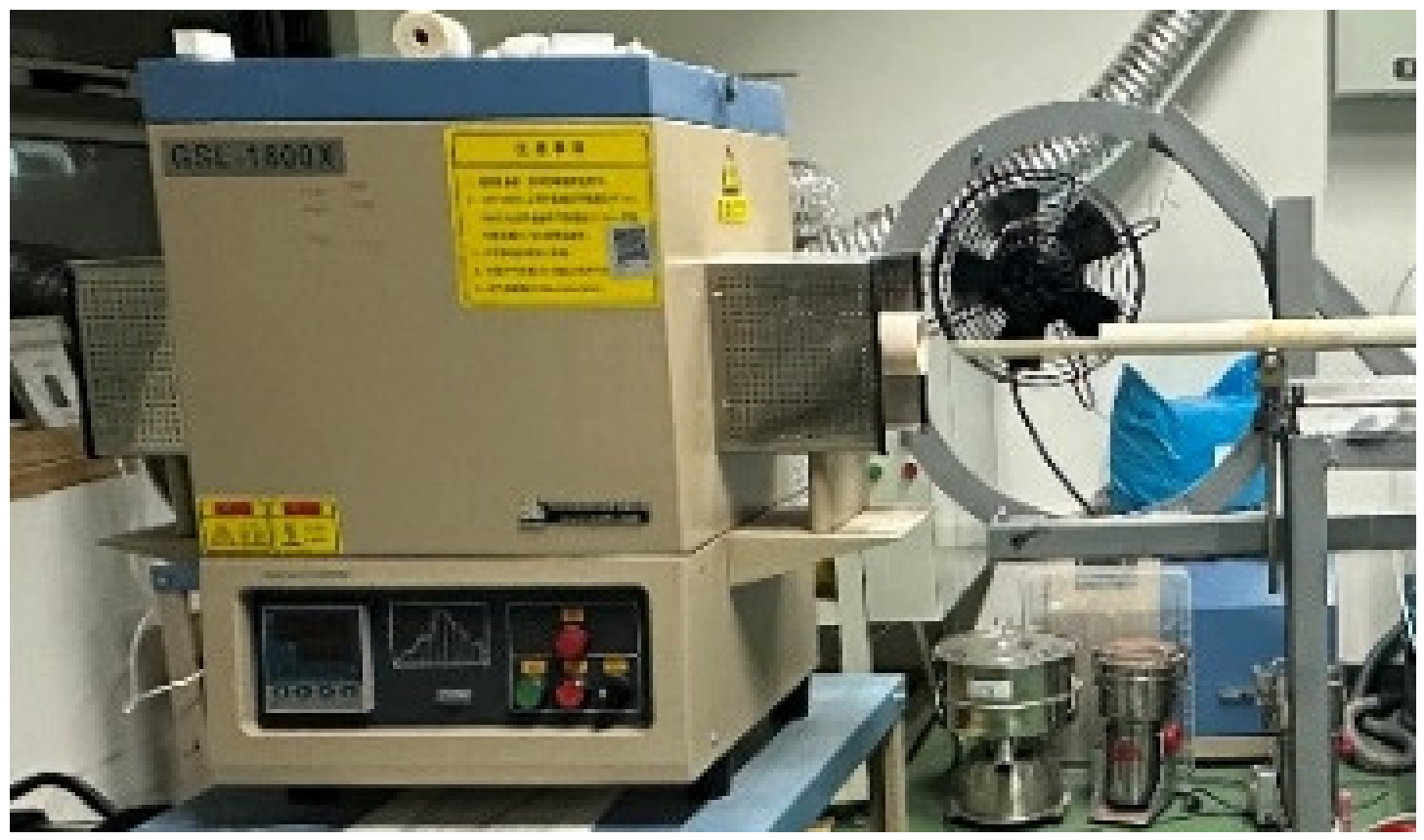
Overheating tests under uniform temperature conditions were conducted by thermal cycling using a GSL 1600X resistive tube furnace (Hefei Kejing Materials Technology Co., Ltd., Hefei, China) shown in Figure 1 and a programmable transfer device. A custom-made quartz long-rod crucible was fixed onto the transfer device to hold the specimens, positioned at the furnace opening. A 24 V industrial fan was placed beside the crucible to cool the specimens. The transfer speed of the device was set to 100 mm/s, and the fan was activated to cool the specimens when they were moved out of the tube furnace.
Under a uniform temperature condition, three groups of specimens were subjected to overheating treatment at 1300 °C for durations of 1 min, 5 min, and 10 min, respectively. For comparison, three additional groups were treated at 1150 °C for 1 min, 5 min, and 10 min. Three test specimens were repeated under each condition.
Subsequently, the overheating-treated specimens were subjected to thermal cycling tests at 1150 °C. Each thermal cycle consisted of a 5 min heating and holding phase followed by a 5 min cooling phase. The test was terminated when the spalled area of the coating surface exceeded 5%, at which point the specimen was considered failed. The spalled area was measured using an image analysis method based on pixel counting.

2.3. Short-Term Overheating Test Under Simulated Service Conditions

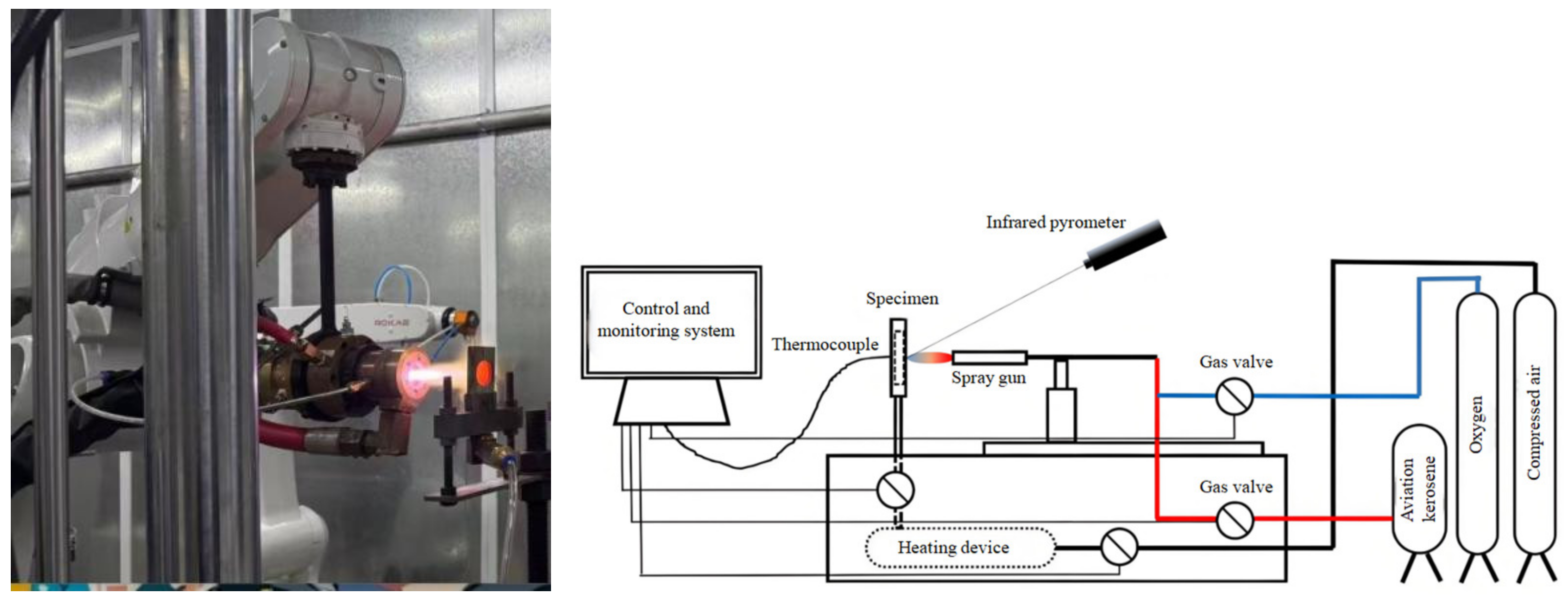
Overheating tests under simulated service conditions were conducted by thermal shock using a custom-built simulation testing platform, as shown in Figure 2. The control system and plasma spray torch were supplied by Zhengzhou Lijia Thermal Spraying Machinery Co., Ltd. (Zhengzhou, China). The cooling system was provided by Taizhou Simpson Electric Heating Technology Co., Ltd. (Taizhou, China). The robotic arm and torch clamping device were manufactured by Luoshi Technology Co., Ltd. (Beijing, China).
The simulated service testing platform generates a plasma flame through ionization of nitrogen gas for surface heating. During the test, the flame was maintained to fully cover the specimen surface, ensuring a uniform temperature distribution. The surface temperature and its uniformity were regulated by adjusting the power parameters, the stand-off distance between the torch and the specimen, and the flow rates of the primary and secondary gases. The backside temperature of the specimen was controlled by regulating the compressed air flow rate from the air compressor. A two-color pyrometer was employed to measure both the surface and backside temperatures. To approximate actual service conditions, the backside temperature was maintained at approximately 550 °C, with a measured deviation within ±10 °C throughout the experiments.
The overheating treatment was performed at 1300 °C for durations of 1 min, 5 min, and 10 min. After overheating treatment, the three groups of specimens were subjected to thermal shock tests under simulated service conditions at 1150 °C. Each cycle consisted of a 5 min heating and holding phase followed by a 5 min forced air cooling phase, resulting in a total cycle duration of 10 min. The tests were conducted following the above cyclic procedure until the coating spalled area on the specimen surface exceeded 5%, at which point the specimen was considered failed. Three test specimens were repeated under each condition. The spalled area was measured using an image analysis method based on pixel counting.

2.4. Coating Characterization

The microstructure of the coatings was examined using scanning electron microscopy (SEM) at an accelerating voltage of 15 keV, a current of 0.8 nA, and a working distance of approximately 15 mm.
Phase constitution was determined via X-ray diffraction (XRD) with a Cu Kα source operated at 15 kV and 1 mA. Data were collected over a 2θ range of 20–90° with a step size of 0.05° and a scan speed of 2°/min.
Residual stresses were evaluated using Raman spectroscopy. A neon laser with a wavelength of 532 nm was employed at a power of 50 mW. Spectra were recorded over the range of 100–800 cm−1 with a resolution of 1 cm−1. For the tetragonal ZrO2 top coat, the peak shift near 640 cm−1 was adopted for stress analysis due to its high signal-to-noise ratio [25]; for TGO, the strongest peak near 418 cm−1 was used.
Raman stress calculation is based on the measurement of the Raman peak shift relative to its stress-free reference position. For a dense, isotropic material under uniaxial stress, the relationship between the Raman peak shift and the stress tensor can be expressed as:
v = v v 0 = U 0 σ U
where v is the peak shift relative to the stress-free state ( v 0 ), U 0 is the stress sensitivity coefficient under uniaxial loading, and σ U is the uniaxial stress. For the 8YSZ material used in this study, the stress sensitivity coefficients have been reported in the literature: U 0 ≈ 1.1 cm−1/GPa under uniaxial stress and H 0 ≈ 2.8–3.2 cm−1/GPa under hydrostatic pressure [25]. The relationship between U 0 and H 0 can be expressed as:
U 0 = 1 3 H 0
Therefore, the stress sensitivity coefficient was approximately taken as 0 ≈ 1.0 cm−1/GPa. Assuming a biaxial stress state, the measured Raman peak shift was converted to stress values using the following relationship:
v = 2 3 H 0 σ t b c I
For the TGO layer, the characteristic Raman peaks were identified and fitted using a pseudo-Voigt profile fitting algorithm. The fitted peak parameters were then compared with the known stress-free reference value of the α-Al2O3 R1 peak. The relationship between the peak shift and the corresponding stress in the TGO can be described as:
v = i j σ i j
where i j is the stress sensitivity coefficient for TGO. Since the TGO thickness varies within the range of 0.5–5 μm during growth, and considering its geometric characteristics, the TGO layer can be idealized as a thin film. Therefore, assuming a biaxial stress state, the measured Raman peak shift was converted to stress using the following relationship:
v = 2 3 ( 11 + 22 + 33 ) σ T G O

3. Results and Discussion

3.1. Appearance of Coating After Failure

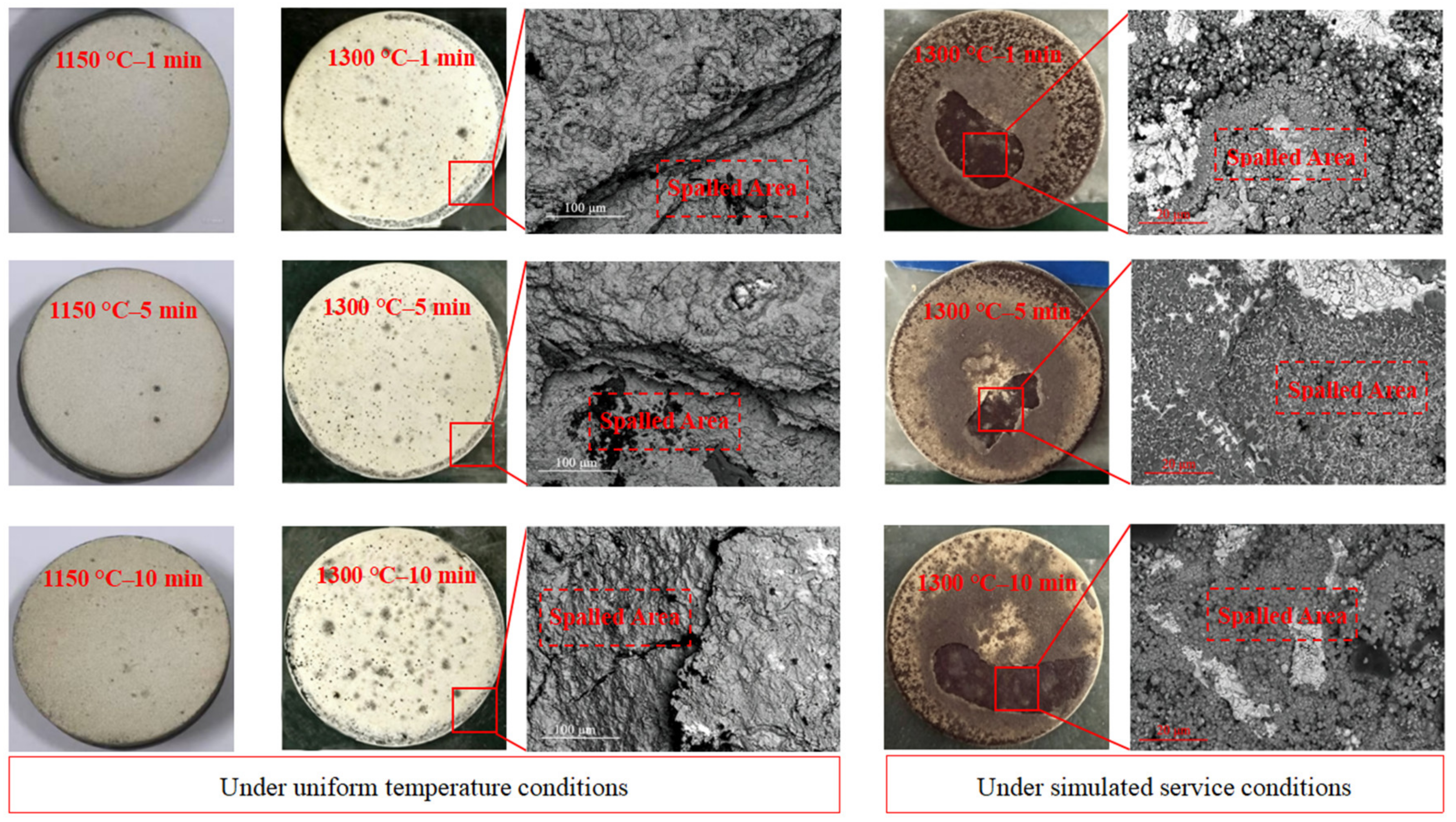
Figure 3 shows the appearance of the coating after failure in short-term overheating tests under different conditions. Under uniform temperature conditions, following a short-term overheating test at 1300 °C, the coating failed after 1500 thermal cycles. Minor defects, characterized by delamination of the ceramic layer, were observed at the edge of all three specimens within the region conventionally defined as one-tenth of the specimen diameter, i.e., within approximately 2.6 mm from the periphery. With increasing overheating duration, the area of edge defects gradually expanded. Scanning electron microscopy revealed a layered spallation morphology, with a partial ceramic layer remaining at the spalled regions. This failure mode is attributed to edge effects governed by geometric factors, which induce thermal stress concentration and subsequently drive delamination and spallation of the ceramic layer at the specimen edges.
In contrast, the reference specimen exposed to 1150 °C exhibited no delamination or spallation defects after 1500 thermal cycles, indicating that overheating at 1300 °C accelerates coating failure.
Under simulated service conditions, the specimen life of the coating after a short-term overheating of 1300 °C for 1 min, 5 min, and 10 min was 41, 30, and 24 times, respectively, with standard deviations of 2.13, 1.81, and 0.88. The longer the overheating duration, the shorter the coating lifetime. Unlike the failure mode observed under uniform temperature conditions, under simulated service conditions, the primary failure location of the coating after thermal shock occurred at the center of the specimen, characterized by large-area spallation of the entire ceramic layer with no residual ceramic remaining. This observation was further confirmed by scanning electron microscopy. This failure mode is likely attributable to the coalescence of cracks within the ceramic layer and interfacial cracks in the TGO layer. Further verification will be provided through subsequent cross-sectional microstructural analysis.

3.2. Microstructural Evolution of Coatings

Figure 4 shows the microstructures of coatings exposed to 1150 °C under uniform temperature conditions for different durations, both before and after thermal cycling tests. The porosity of the coatings after isothermal exposure for 1, 5, and 10 min was determined to be 14.2%, 11.5%, and 9.8%, respectively, through gray-scale threshold image analysis. After 1 min at 1150 °C, no distinct TGO layer was observed. With increasing duration, the TGO thickness gradually increased, reaching 0.3 µm after 5 min and 1.1 µm after 10 min. However, after 1500 thermal cycles, the TGO thickness fluctuated around 3.6 µm for all three specimens, with negligible differences. After thermal cycling, microcracks appeared due to local stress induced by undulations at the ceramic/TGO interface, though crack propagation remained limited.
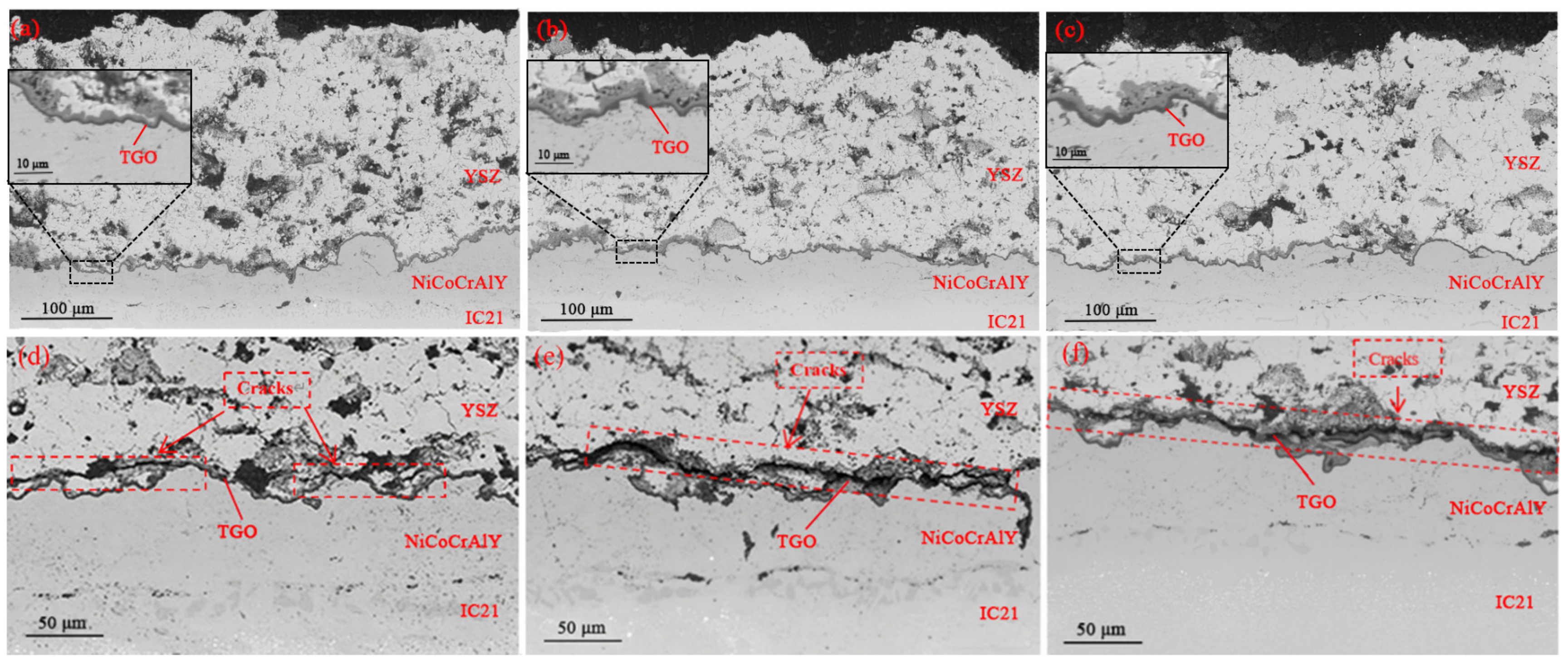
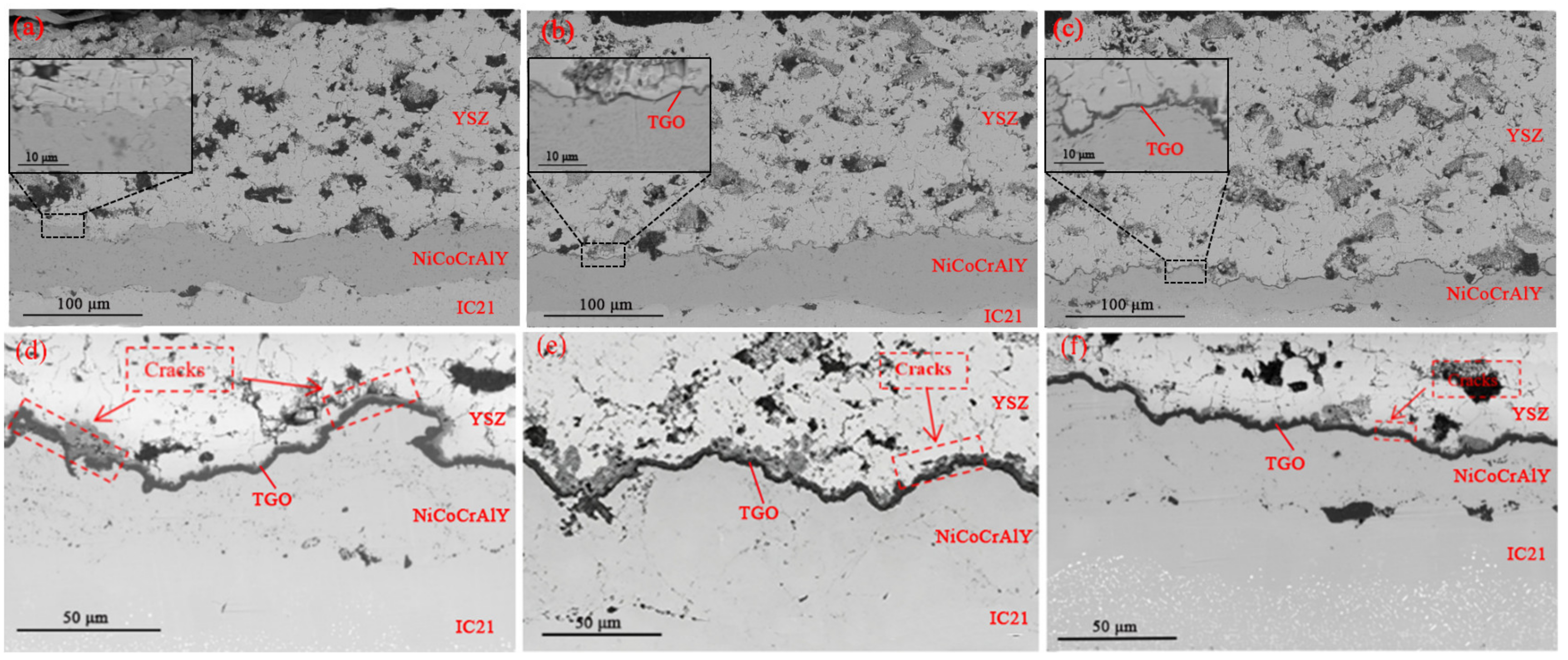
Figure 5 shows the microstructures of coatings exposed to 1300 °C under uniform temperature conditions for different overheating durations, both before and after thermal cycling. After short-term overheating at 1300 °C, TGO growth accelerated significantly, reaching 2.1 µm after just 1 min. The growth rate slowed after 5 min, with a thickness of 2.8 µm, and increased to 3.0 µm after 10 min. Compared to the microstructures after the same durations at 1150 °C, the coating porosity decreased (13.3%, 10.1%, and 8.7%, respectively), and the coating became denser after overheating. Moreover, with increasing overheating duration, porosity exhibited a decreasing trend, indicating sintering of the coating. After 1500 thermal cycles, the TGO thickness fluctuated around 3.6 µm, consistent with that after thermal cycling at 1150 °C. Cracks at the ceramic/TGO interface accelerated and propagated laterally, with microcracks in the specimen overheating for 5 min gradually connecting to form macroscopic cracks.
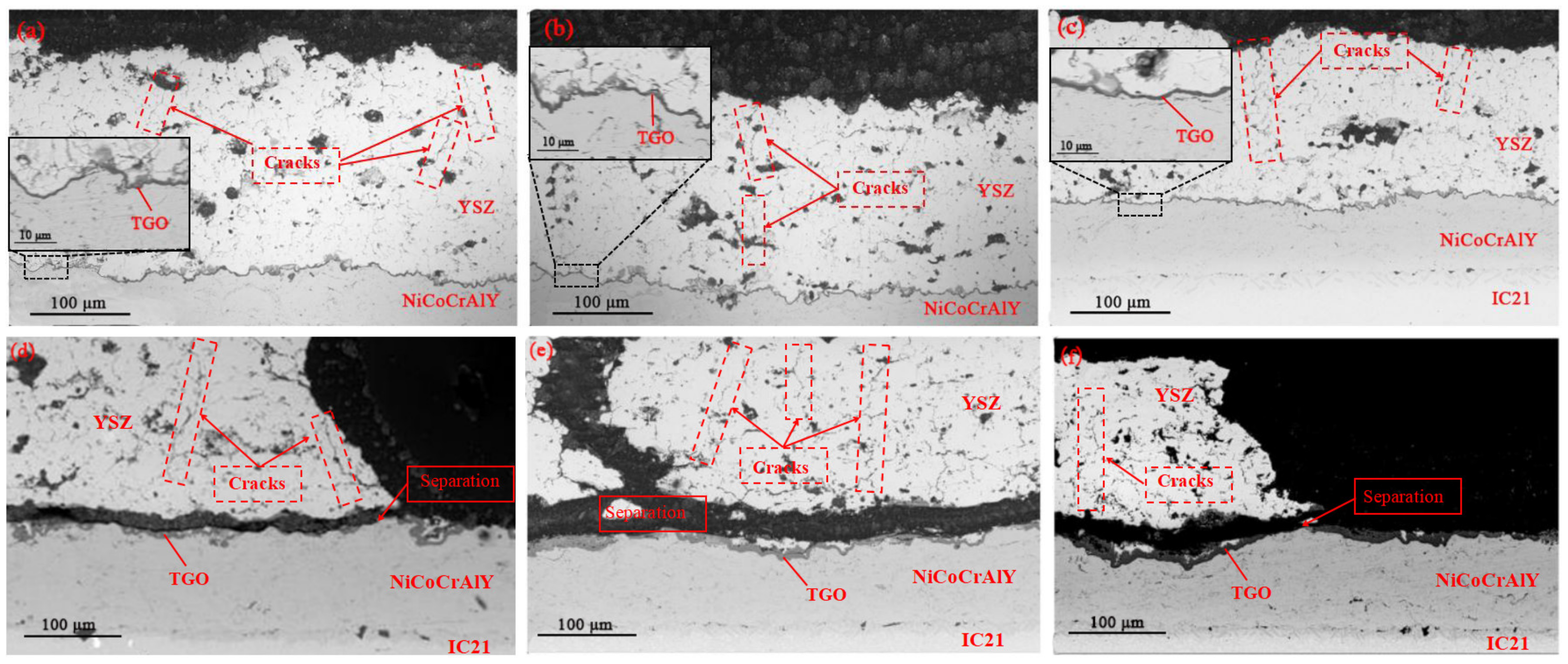
Figure 6 shows the microstructures of coatings exposed to 1300 °C under simulated service conditions for different overheating durations, both before and after thermal shock. Compared with uniform temperature conditions, the TGO thickness was smaller after the same overheating duration under simulated service conditions. For overheating durations of 1 min, 5 min, and 10 min, the TGO thicknesses were 1.5 µm, 2.0 µm, and 2.4 µm, respectively. This difference is attributed to the presence of a temperature gradient within the coating under simulated service conditions, resulting in a lower interface temperature than that under uniform temperature conditions. With increasing overheating duration, the porosity of the ceramic layer decreased (9.6%, 8.6%, and 8.1%, respectively), and sintering occurred. Additionally, vertical cracks appeared within the coating, attributed to the reduced toughness of the sintered ceramic layer under the temperature gradient. The formation of vertical cracks provided pathways for inward oxygen diffusion, accelerating degradation at the interface.
During subsequent gas thermal shock, cracks within the ceramic layer propagated continuously. When interfacial degradation reached a critical level, coating failure occurred. Microstructural examination of the failed coating revealed separation between the ceramic layer and the bond coat, with failure cracks penetrating through the TGO layer. Simultaneously, numerous penetrating cracks were also observed within the ceramic layer. Thus, after short-term overheating, vertical cracks form in the ceramic layer due to the internal–external temperature gradient, and the high-velocity gas impact further promotes rapid crack propagation. Enhanced inward oxygen diffusion accelerates interfacial degradation, which, together with the propagation of vertical cracks in the ceramic layer, leads to large-area spallation at the central region of the coating, thereby significantly reducing the service life. Longer overheating exposure corresponds to shorter coating lifetime.
Combining cross-sectional microstructural analysis with post-failure morphology, it is evident that the failure mechanisms of the coating after short-term overheating differ between the two test conditions. Specifically, the edge delamination and spallation of the coating caused by edge stress concentration governed by geometric factors transitioned to overall central spallation driven by interfacial instability resulting from microstructural evolution at the interface.

3.3. Stress Evolution of Coatings

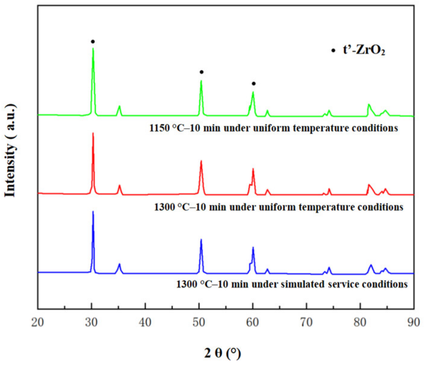
XRD analysis was performed on the coatings after short-term overheating under both testing conditions. The diffraction patterns exhibited exclusively the peaks corresponding to the metastable tetragonal t’-ZrO2 phase, with no additional peaks or peak shifts being detected. This indicates that no phase transformation or formation of new phases occurred in the coatings after short-term overheating and subsequent failure under the two conditions. Figure 7 presents the XRD patterns of the failed coatings after short-term overheating for 10 min under the two conditions.
To investigate the effect of short-term overheating on the stress within TBC systems, Raman spectroscopy was employed to measure the residual stresses in the ceramic layer and the TGO of specimens held for different durations under uniform temperature and simulated service conditions.
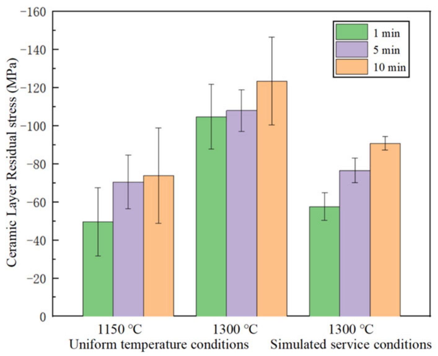
Figure 8 shows the ceramic layer residual stress after different overheating durations. Specimens insulated at 1150 °C under uniform temperature are taken as the reference group. The negative values indicate compressive stress within the ceramic layer. Under uniform temperature conditions at 1150 °C for 1, 5, and 10 min, the ceramic layer stresses were 49.6, 70.6, and 73.9 MPa, respectively. At 1300 °C for the same durations, the stresses were 104.7, 108.0, and 123.5 MPa, respectively. Under uniform temperature conditions, residual stress increases with both overheating duration and temperature; however, the evolution differs across temperatures. For the reference group at 1150 °C, residual stress reached a steady state after 5 min, increasing by only 3.3 MPa after 10 min. In contrast, for the three specimens at 1300 °C, residual stress reached a steady state as early as 1 min, peaking after 10 min. Under simulated service conditions with overheating at 1300 °C, the stress was slightly lower than that under uniform temperature overheating conditions, measuring 57.6, 76.6, and 90.8 MPa after 1, 5, and 10 min, respectively. Combined with microstructural analysis, this reduction is attributed to stress relief caused by sintering-induced cracks within the ceramic layer. The overall increasing trend of residual stress with overheating duration gradually accelerated, and no relative steady state of residual stress was observed after 1 min.
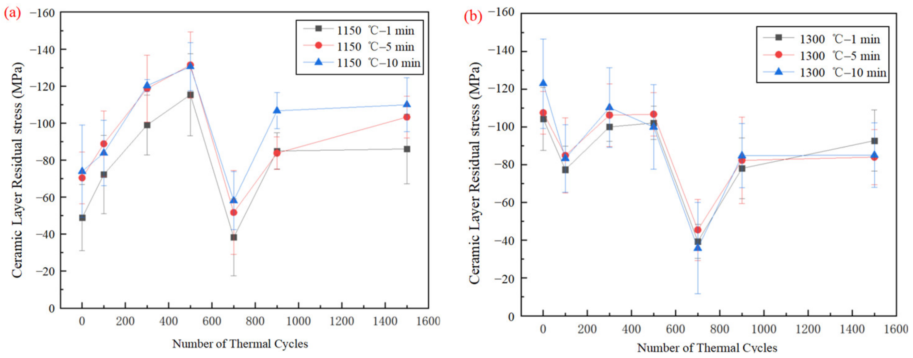
To further understand the evolution of ceramic layer stress during thermal cycling, stress measurements were conducted under uniform temperature conditions after different cycle numbers (100, 300, 500, 700, 900, 1500). Figure 9 shows the stress evolution curve of the ceramic layer during thermal cycling after short-term overheating under uniform temperature conditions. Stress evolution under simulated service conditions was not measured due to the shorter coating cycle life.
Figure 9a shows that, at the same temperature, the general trend of ceramic layer stress with cycle number is largely consistent across the three specimens with different durations. For specimens at 1150 °C, within the first 500 cycles, ceramic layer stress exhibited continuous accumulation, reaching a maximum compressive stress of 130 MPa. At 700 cycles, the compressive stress dropped sharply to 40 MPa, primarily due to stress release caused by damage at the coating interface. Subsequently, stress increased and reached a dynamic equilibrium between 80 and 110 MPa. The overheating duration did not alter the overall stress evolution trend. From Figure 9b, after short-term overheating at 1300 °C, the ceramic layer stress in the three specimens peaked immediately, indicating that significant internal stress was induced during the initial stage of overheating. During subsequent thermal cycling, the compressive stress first released to 80 MPa. Between 300 and 500 cycles, compressive stress re-accumulated to 100 MPa. Similar to the 1150 °C case, after 700 cycles, compressive stress released to a minimum of 40 MPa, then re-accumulated to 80 MPa and reached a dynamic equilibrium between 80 and 100 MPa.
The essence of ceramic layer stress evolution is a dynamic process driven by thermal mismatch stress, involving initiation, evolution, and eventual stabilization of internal damage. Changes in overheating temperature affect the microstructure of the ceramic layer, altering its initial damage state and strength, thereby influencing the stress evolution process. However, overheating duration has a relatively minor effect.
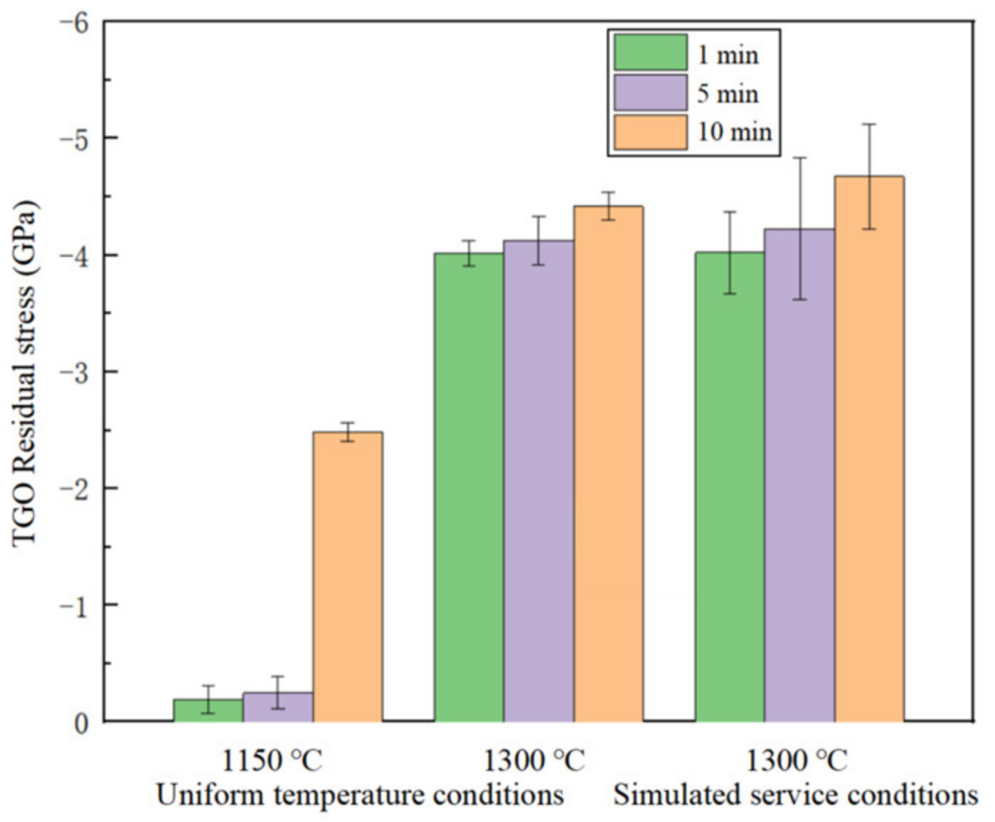
Figure 10 shows the TGO residual stress after different overheating durations. Negative values indicate compressive stress within the TGO. Under uniform temperature conditions, TGO residual stress increased with overheating temperature. For the 1150 °C reference group, residual stresses after 1 and 5 min were relatively low (0.2 and 0.25 GPa, respectively), but increased rapidly to 2.5 GPa after 10 min. For the three specimens at 1300 °C, TGO residual stress quickly increased to 4.0 GPa, with slower subsequent growth: 4.1 GPa and 4.4 GPa after 5 and 10 min, respectively. Under simulated service conditions at 1300 °C, TGO stress was generally consistent with uniform temperature conditions, which were 4.0, 4.2, and 4.6 GPa, respectively, slightly higher by 0.1–0.2 GPa.
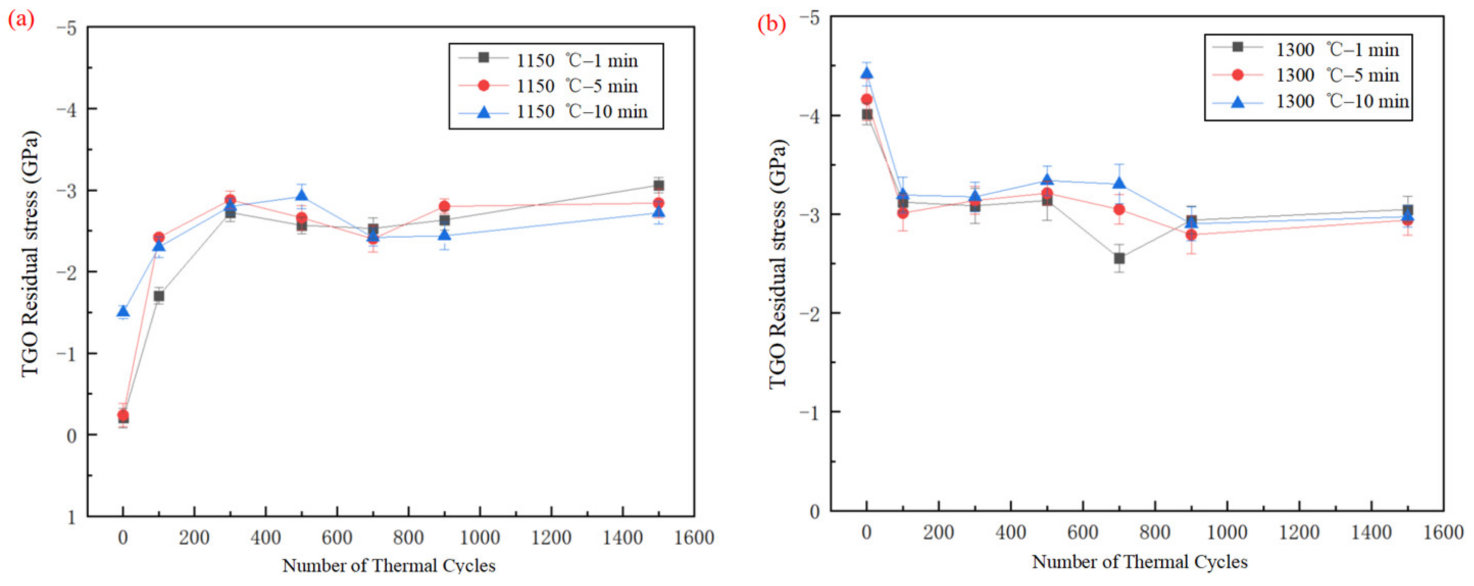
TGO residual stress under uniform temperature conditions was also measured after different cycle numbers (100, 300, 500, 700, 900, 1500). Figure 11 shows the stress evolution curve of the TGO during thermal cycling after short-term overheating under uniform temperature conditions. The figure shows that TGO residual stress remained generally stable during thermal cycling across specimens. For the three specimens at 1150 °C, TGO residual stress stabilized within 2.5–3.0 GPa. When the overheating temperature increased to 1300 °C, TGO residual stress peaked immediately after overheating, gradually released during thermal cycling, and stabilized within 3.0–3.5 GPa. This suggests that overheating treatment at this temperature induces damage within the TGO layer, leading to stress release followed by dynamic equilibrium.
The essence of TGO residual stress evolution is the result of the initial damage at the interface determined by overheating temperature, and the damage accumulation-release mechanism during thermal cycling. During short-term overheating, higher overheating temperatures lead to greater initial damage and TGO compressive stress, more pronounced subsequent stress release and equilibrium behavior, ultimately determining the stable stress range. Overheating duration only affects the magnitude of TGO residual stress but has little influence on its overall evolution trend.

3.4. Mechanisms of Short-Term Overheating Damage of TBCs

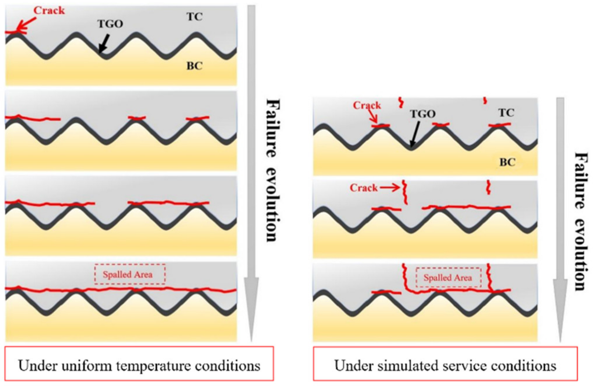
The mechanisms of short-term overheating damage of TBCs vary significantly under different conditions, primarily due to differences in the intensity of thermal-mechanical-chemical coupling and the dominant crack propagation modes. Figure 12 shows the schematic diagram of crack propagation under different conditions.
Under uniform temperature conditions, failure evolution is governed by TGO. Local stresses induced by the undulating topography of the ceramic/TGO interface generate horizontal microcracks within the coating. Meanwhile, interfacial shear stresses arising from edge effects lead to the initiation of interfacial cracks preferentially at the specimen edges. As thermal cycling progresses, these cracks propagate and, synergistically with the continuously thickening TGO, promote the coalescence of microcracks into macroscopic cracks, eventually causing coating failure. Overheating primarily drives the continuous growth of TGO, with stress evolution exhibiting a relatively gradual dynamic process correlated with microstructural changes at the interface.
Under simulated service conditions, the failure mechanism is co-governed by localized degradation of the coating interface and crack propagation within the ceramic layer. The transient heat input from high-velocity hot gas impingement induces vertical cracks inside the ceramic layer. These cracks extend downward under the sustained gas impact and interconnect with the ceramic/TGO interfacial cracks, ultimately triggering local spallation in the central region of the coating. Overheating predominantly causes sintering-induced cracking of the ceramic layer. During this process, the overheating temperature and duration only affect the service life without altering the failure mode. Furthermore, the stress state within the ceramic layer is directly coupled to the initiation and propagation of internal cracks.
In summary, the short-term overheating failure mechanisms of TBCs under different conditions exhibit a transition from edge stress concentration failures governed by geometric factors to overall interface instability driven by microstructural evolution at the central interface, which subsequently leads to local failure of the central coating. As test conditions become more severe, the synergistic effect of temperature gradient and thermal impact accelerates crack initiation and propagation in the ceramic layer as well as interfacial degradation, significantly reducing coating lifetime.
This study is conducted based on the APS process, which remains the most widely applied and cost-effective engineering approach in the field of TBCs. In contrast to the lamellar porous structure characteristic of APS coatings, electron beam-physical vapor deposition (EB-PVD) coatings exhibit a columnar grain structure with higher strain tolerance. Meanwhile, the emerging plasma spray-physical vapor deposition (PS-PVD) technology combines the high deposition efficiency of APS with the columnar-grain advantages of EB-PVD, enabling non-line-of-sight deposition on complex-shaped components, and is widely recognized as a significant direction for the next-generation TBC fabrication techniques. This study focuses on the damage mechanisms of APS coatings under short-term overtemperature conditions. The failure patterns revealed herein are intended to serve as baseline references for subsequent comparative investigations on coatings prepared by advanced processes such as EB-PVD or PS-PVD under analogous extreme conditions. Future work will build upon these findings to further explore the influence of advanced coating processes on overtemperature damage resistance, and to establish cross-process lifetime prediction models integrated with finite element simulations.

4. Conclusions

(1)
Under uniform temperature, failure occurs at the specimen edge as delamination, driven by thermal stress concentration from edge effects, with overheating promoting TGO growth. Under simulated conditions, failure occurs at the specimen center as spallation, governed by crack coalescence between the ceramic layer and TGO, with overheating inducing sintering.
(2)
Stress evolution differs in thermal mismatch stress generation and relaxation: under uniform temperature, stress evolves mildly with microstructure; under simulated conditions, steep thermal gradients generate high non-steady stress relieved by ceramic cracking.
(3)
The damage mechanisms differ in thermal-mechanical-chemical coupling intensity and cracking mode. Uniform temperature leads to long-term interfacial degradation; simulated conditions accelerate degradation through synergistic sintering and TGO destabilization, significantly reducing lifetime.

Author Contributions

Conceptualization, M.Z. and Y.S.; methodology, M.Z., Y.F., Y.S. and J.M.; validation, M.Z. and Y.S.; formal analysis, M.Z., J.Z. and Y.S.; investigation, M.Z., Y.F. and Y.S.; resources, Y.S. and Y.P.; data curation, M.Z., C.L. and Y.S.; writing—original draft preparation, M.Z.; writing—review and editing, M.Z., Y.F. and Y.S.; visualization, M.Z. and Y.S.; supervision, S.G. and Y.P.; project administration, S.G.; funding acquisition, Y.S. All authors have read and agreed to the published version of the manuscript.

Funding

This research was funded by the Funds of the National Key R&D Program of China (No. 2024YFB3715200) and the Key R&D Program of Zhejiang (No. 2024SSYS0075).

Informed Consent Statement

Informed consent was obtained from all subjects involved in the study.

Data Availability Statement

The original contributions presented in this study are included in the article. Further inquiries can be directed to the corresponding author.

Conflicts of Interest

Author Mourui Zhang was employed by the company AECC Shenyang Liming Aero–Engine Co., Ltd. The remaining authors declare that the research was conducted in the absence of any commercial or financial relationships that could be construed as a potential conflict of interest.

References

  1. Mondal, K.; Nuñez, L.; Downey, C.M.; Van Rooyen, I.J. Thermal barrier coatings overview: Design, manufacturing, and applications in high-temperature industrie. Ind. Eng. Chem. Res. 2021, 60, 6061–6077. [Google Scholar] [CrossRef]
  2. Chen, X.H.; Wang, Y.Z.; Long, Y.; Weng, S. Effect of Particle Deposition on Film Cooling from Fan-Shaped Hole. Int. J. Heat Mass Transf. 2021, 181, 122028. [Google Scholar] [CrossRef]
  3. Clarke, D.R.; Oechsner, M.; Padture, N.P. Thermal-barrier coatings for more efficient gas-turbine engines. MRS Bull. 2012, 37, 891–898. [Google Scholar] [CrossRef]
  4. Vaßen, R.; Jarligo, M.O.; Steinke, T.; Mack, D.E.; Stöver, D. Overview on advanced thermal barrier coatings. Surf. Coat. Technol. 2010, 205, 938–942. [Google Scholar] [CrossRef]
  5. Guo, H.B.; Gong, S.K.; Xu, H.B. Progress in Thermal Barrier Coatings for Advanced Aeroengines. Mater. China 2009, 28, 18–26. (In Chinese) [Google Scholar]
  6. Padture, N.P.; Gell, M.; Jordan, E.H. Thermal barrier coatings for gas-turbine engine applications. Science 2002, 296, 280–284. [Google Scholar] [CrossRef] [PubMed]
  7. Sun, R.Y.; Li, Y.M.; Li, Q.; Huang, M.T.; Zhou, M.Z. Study on the high temperature failure mechanism of aero-engine high pressure turbine guide blade. Chin. J. Turbomach. 2023, 65, 87–91. (In Chinese) [Google Scholar]
  8. Pakseresht, A.; Sharifianjazi, F.; Esmaeilkhanian, A.; Bazli, L.; Nafchi, M.R.; Bazli, M.; Kirubaharan, K. Failure mechanisms and structure tailoring of YSZ and new candidates for thermal barrier coatings: A systematic review. Mater. Des. 2022, 222, 111044. [Google Scholar] [CrossRef]
  9. Zhao, W.X.; Li, Y.; Fan, Y.W.; Zhen, Y.R. Facture analysis for second stage rotor turbine blade in aero-engine. J. Mater. Eng. 2012, 8, 39–44. (In Chinese) [Google Scholar]
  10. Bachnio, J.; Izydor, W. Damageability of Gas Turbine Blades—Evaluation of Exhaust Gas Temperature in Front of the Turbine Using a Non-Linear Observer. In Gas Turbine Technology; Benini, E., Ed.; InTech: Shanghai, China, 2011. [Google Scholar]
  11. Giraud, R.; Hervier, Z.; Cormier, J.; Saint-Martin, G.; Hamon, F.; Milhet, X.; Mendez, J. Strain Effect on the γ′ Dissolution at High Temperatures of Single Crystal Superalloy. Metall. Mater. Trans. A 2013, 44, 131–146. [Google Scholar]
  12. Yuan, J.; Hu, H.; Zhang, H.; Wei, C.; Li, S.; Lu, X. Multicomponent high-entropy rare earth hexaaluminate thermal barrier coating with prolonged thermal cycling performanc. Surf. Coat. Technol. 2025, 511, 132255. [Google Scholar] [CrossRef]
  13. Sun, F.; Chen, Y.; Li, D.; Xu, R.; Jiang, P.; Wang, T. Over temperature in thermal barrier coating system induced by local spallation of ceramic layer. Appl. Therm. Eng. 2025, 269, 126121. [Google Scholar] [CrossRef]
  14. Thakare, J.G.; Pandey, C.; Mahapatra, M.M.; Mulik, R. Thermal barrier coatings—A state of the art review. Met. Mater. Int. 2020, 27, 1947–1968. [Google Scholar] [CrossRef]
  15. Liu, Y.W.; Li, C.; Feng, S.Z.; Wang, Y.; Zhou, S.J.; Jin, S. Research Progress on Failure Mechanism, Material Selection and Structural Design of Long-life Thermal Barrier Coatings. China Surf. Eng. 2024, 37, 220–237. (In Chinese) [Google Scholar]
  16. Guo, L.; Gao, Y.; Ye, F.X.; Zhang, X.M. CMAS corrosion behavior and protection method of thermal barrier coatings for aeroengine. Acta Metall. Sin. 2021, 57, 1184–1198. (In Chinese) [Google Scholar]
  17. Feng, Y.; Dong, T.S.; Li, G.L.; Wang, R.; Ma, G.Z.; Zhao, X.W.; Liu, Q. The roles of stress in the thermal shock failure of YSZ TBCs before and after laser remelting. J. Alloys Compd. 2020, 828, 154417. [Google Scholar] [CrossRef]
  18. Park, S.; Kim, D.J.; Kim, J.Y.; Kim, S.J.; Seok, C.S. Thermal Fatigue Life Evaluation of EB-PVD TBC Using Newly Developed Small-scale Burner Rig. J. Korean Soc. Precis. Eng. 2025, 42, 65–73. [Google Scholar] [CrossRef]
  19. Dong, H.; Yang, G.J.; Cai, H.N.; Ding, H.; Li, C.X.; Li, C.J. The Influence of Temperature Gradient across YSZ on Thermal Cyclic Lifetime of Plasma-Sprayed Thermal Barrier Coating. Ceram. Int. 2015, 41, 11046–11056. [Google Scholar] [CrossRef]
  20. Shind, Y.; Hamed, A. Influence of micro-structure on erosion resistance of plasma sprayed 7YSZ thermal barrier coating under gas turbine operating conditions. Wear 2018, 396–397, 34–47. [Google Scholar] [CrossRef]
  21. Hille, T.S.; Nijdam, T.J.; Suiker, A.S.J.; Turteltaub, S.; Sloof, W.G. Damage growth tplatformgered by interface irregularities in thermal barrier coatings. Acta Mater. 2009, 57, 2624–2630. [Google Scholar] [CrossRef]
  22. Yan, W.L.; Yang, L.; Zhou, Y.C.; Yan, G.; Li, C. Research progress of service environment simulation test methods for thermal barrier coatings. Aeronaut. Manuf. Technol. 2023, 66, 38–45. (In Chinese) [Google Scholar]
  23. Zhang, M.; Wang, Y.; Feng, Y.; Shang, Y.; Gong, S.; Cheng, Y. Failure Mechanism Analysis of Thermal Barrier Coatings under a Service Simulation Environment. Coatings 2025, 15, 78. [Google Scholar] [CrossRef]
  24. Ru, Y.; Zhang, H.; Pei, Y.L.; Li, S.; Zhao, X.; Gong, S.K. Improved 1200 ℃ Stress Rupture Property of Single Crystal Superalloys by γ′-Forming Elements Addition. Scr. Mater. 2018, 147, 21–26. [Google Scholar] [CrossRef]
  25. Vasco, T.; Michael, A.; Wolfgang, F.; Buchkremer, H.P.; Stöver, D. Analysis of Residual Stresses in Thermal Barrier Coatings. J. Mater. Process. Technol. 1999, 92–93, 209–216. [Google Scholar] [CrossRef]
Figure 1. GSL 1600X resistive tube furnace.
Coatings 16 00919 g001
Figure 2. The custom-built simulation testing platform.
Coatings 16 00919 g002
Figure 3. The appearance of the coating after failure in short-term overheating tests under different conditions.
Coatings 16 00919 g003
Figure 4. The microstructures of coatings exposed to 1150 °C under uniform temperature conditions for different durations, both before and after thermal cycling tests. (a) 1150 °C–1 min, (b) 1150 °C–5 min, (c) 1150 °C–10 min before thermal cycling tests; (d) 1150 °C–1 min, (e) 1150 °C–5 min after, (f) 1150 °C–10 min after thermal cycling tests.
Coatings 16 00919 g004
Figure 5. The microstructures of coatings exposed to 1300 °C under uniform temperature conditions for different overheating durations, both before and after thermal cycling. (a) 1300 °C–1 min, (b) 1300 °C–5 min, (c) 1300 °C–10 min before thermal cycling tests; (d) 1300 °C–1 min, (e) 1300 °C–5 min after, (f) 1300 °C–10 min after thermal cycling tests.
Coatings 16 00919 g005
Figure 6. The microstructures of coatings exposed to 1300 °C under simulated service conditions for different overheating durations, both before and after thermal shock. (a) 1300 °C–1 min, (b) 1300 °C–5 min, (c) 1300 °C–10 min before thermal shock; (d) 1300 °C–1 min, (e) 1300 °C–5 min after, (f) 1300 °C–10 min after thermal shock.
Coatings 16 00919 g006
Figure 7. The XRD patterns of the failed coatings after short-term overheating for 10 min under the two conditions.
Coatings 16 00919 g007
Figure 8. The ceramic layer residual stress after different overheating durations.
Coatings 16 00919 g008
Figure 9. The stress evolution curve of the ceramic layer during thermal cycling after short-term overheating under uniform temperature conditions (a) at 1150 °C, (b) at 1300 °C.
Coatings 16 00919 g009
Figure 10. The TGO residual stress after different overheating durations.
Coatings 16 00919 g010
Figure 11. The stress evolution curve of the TGO during thermal cycling after short-term overheating under uniform temperature conditions (a) at 1150 °C, (b) at 1300 °C.
Coatings 16 00919 g011
Figure 12. Schematic diagram of crack propagation under different conditions.
Coatings 16 00919 g012
Table 1. The chemical composition of IC21.
CompositionAlTaMoCoCrReNi
wt.%5.4~9.84.0~7.56.9~9.33.7~6.11.3~3.71.4~4.6Bal.
Table 2. The process parameters for HVOF of the bond coat.
NameAir Flow RatePropane Flow RatePowder Feed RateSpraying Distance
Parameter84.2 L/min86.5 L/min20 g/min150 mm
Table 3. The process parameters for APS of the top coat.
NameArc CurrentArc VoltageAr2 Flow RateH2 Flow RatePowder Feed RateSpraying Distance
Parameter560 A59 V35 L/min6.5 L/min40 g/min120 mm
Disclaimer/Publisher’s Note: The statements, opinions and data contained in all publications are solely those of the individual author(s) and contributor(s) and not of MDPI and/or the editor(s). MDPI and/or the editor(s) disclaim responsibility for any injury to people or property resulting from any ideas, methods, instructions or products referred to in the content.