Article

Effect of Pulsed Substrate Bias on the Micromechanical Properties, Edge Integrity, and Machining Performance of Cathodic Arc AlTiN Coatings


1
McMaster Manufacturing Research Institute, McMaster University, Hamilton, ON L8P 0A6, Canada
2
Kennametal GmbH, 91320 Ebermannstadt, Germany
*
Author to whom correspondence should be addressed.
Coatings 2026, 16(6), 639; https://doi.org/10.3390/coatings16060639
Submission received: 28 April 2026 / Revised: 18 May 2026 / Accepted: 21 May 2026 / Published: 25 May 2026
(This article belongs to the Special Issue Tribology of Coatings and Surface Layers)

Abstract

Controlling deposition parameters is fundamental to obtaining the desired properties of cathodic arc physical vapor deposition (PVD) coatings. Achieving uniform coatings on tools with complex, sharp geometries remains a significant challenge due to localized ion flux concentration. Pulsing the substrate bias is an effective way of controlling deposition energy. However, while widely used in cathodic arc PVD, the relationship between the actual bias waveform, coating integrity on sharp tool geometries, and resulting machining performance has not been systematically established. This study investigates the effect of pulsed bias duty cycle (20% to 90%) and frequency (1 to 20 kHz) on the microstructural evolution, residual stress state, and machining performance of AlTiN coated tools. Real-time oscilloscope measurements demonstrated that system inductance and capacitance significantly distort the ideal bias waveform. Microstructural analysis via Focused Ion Beam/Scanning Electron Microscopy (FIB/SEM) cross-sectioning confirmed that all bias parameters generated a dense microstructure. While pulse frequency had no significant influence on micromechanical properties or residual stress states, the duty cycle was the dominant variable. High-energy deposition (90% duty cycle) increased hardness to 33.9 GPa but generated severe compressive residual stresses (−5.2 GPa). This extreme compressive stress led to catastrophic edge delamination on sharp solid carbide endmills. Conversely, a low-energy 20% duty cycle generated a coating with lower hardness (29.4 GPa) and a near-neutral stress state (0.5 GPa), effectively preserving the edge integrity. Unlike the endmills, the turning inserts maintained their edge integrity across all deposition conditions. During the high-speed (350 m/min) dry turning of AISI 304 stainless steel, all evaluated coatings exhibited comparable tool life and cutting forces. Wear progression was characterized by rake cratering, combined with abrasion and adhesion-induced attrition on the flank. The results indicate that tool life in this extreme environment is governed primarily by high-temperature thermo-chemical stability rather than initial room-temperature hardness. Lower-energy pulsed bias deposition therefore represents a robust strategy for coating a wide range of tool geometries, delivering equivalent high-speed machining performance while preventing stress-induced delamination on sharp features.

1. Introduction

Metal cutting processes generate high localized stress, severe plastic strain, and heat accumulation, all of which accelerate tool wear and reduce machining performance [1,2]. To withstand these harsh conditions, physical vapor deposition (PVD) of protective coatings is extensively used to improve tool life and allow higher material removal rates [3]. An ideal coating presents high hardness, anti-friction properties, chemical inertness, and oxidation resistance [4]. Among the available PVD methods, Cathodic Arc Evaporation is largely used for the deposition of hard coatings on cutting tool applications. This technique utilizes a high-current electric arc that vaporizes a metallic target (cathode), creating a highly ionized plasma [5]. In reactive processes, this plasma interacts with background gas and condenses onto a substrate as a thin film [6].
Due to the high mobility of electrons, in most PVD systems, the bulk plasma potential remains slightly positive. Applying a negative bias to the substrate creates a steep potential difference near the substrate that accelerates the positively charged ions towards the substrate surface [5,7]. Controlling the bias, and therefore the energy of arriving ions, directly influences the growth kinetics, adhesion, microstructure, and mechanical properties of the coatings [8,9,10,11,12].
However, coating complex geometries with sharp angles and radii, such as cutting tools, poses a significant challenge [13,14,15]. When a tool interacts with the plasma, a boundary region known as plasma sheath forms around it [7]. While on flat surfaces the electric field within this sheath remains relatively uniform, it becomes severely distorted in geometric transitions, such as the sharp edges of cutting tools [16]. In these regions, the field lines concentrate causing an increased ion flux, often referred to as the “antenna effect” [17]. This uneven, localized bombardment generates a spatial gradient of properties across the tool [18]. If the ion bombardment is excessively aggressive, localized stresses can compromise the tool integrity, leading to coating delamination and even damaging the cutting edge [15].
An effective way of controlling this ion energy is by pulsing the substrate bias [10]. By modulating the duty cycle and frequency of these pulses, the energy of the arriving ions can be finely controlled. Existing literature generally agrees that increasing the duty cycle generates elevated hardness [9] and compressive residual stresses [19]. Furthermore, recent fundamental studies have shown that varying the duty cycle not only affects the energy supplied but also influences the coating growth, microstructure, and defect structure. While a higher duty cycle increases the average ion energy and adatom mobility, the sustained high-energy ion bombardment simultaneously induces atomic peening, generating a structure with increased lattice defect density [9]. The role of pulse frequency is also critical, being predominantly studied regarding its effect on the reduction in the coating’s macroparticle (MP) density [20,21,22], albeit with conflicting conclusions. Beyond that, the pulse frequency is fundamentally important because it interacts directly with the capacitance and inductance of the plasma and power supply. As a result, the actual waveform experienced at the tool surface deviates significantly from the ideal programmed square wave [5,19]. This effect is intensified when using higher frequencies, as the time for each pulse becomes shorter.
While controlling the substrate bias is fundamental to achieving desired coating properties, a critical question remains regarding their practical application in machining. Is a fundamentally harder and denser coating always advantageous for machining? Conventional coating development often aims to maximize hardness [23]. However, achieving this through high-energy bombardment can be detrimental to sharp geometries due to the increased risk of edge delamination [15,24]. If using lower-energy parameters, such as reduced duty cycle, maintains adequate edge integrity across a variety of tool geometries while keeping equivalent machining performance, this would represent a more commercially viable solution. Furthermore, the need for extreme coating hardness is highly dependent on the workpiece material. During machining of materials with a high tendency for adhesion, a moderately hard but significantly tougher coating can achieve superior performance [25]. This enhanced toughness allows the coating to withstand intensive localized sticking and tearing without chipping, ultimately maintaining a more stable performance [2,26,27].
This work aims to investigate the effects of substrate pulsed bias on the edge integrity of cutting tools and their resultant machining performance. AlTiN was selected as the benchmark coating due to its widespread use [28,29,30,31,32,33,34,35,36] and exceptional performance in high-speed machining, where it is often recommended as the first option for stainless steel alloys. To this end, this study evaluates the actual electrical response of the pulsed bias system and investigates how it influences micromechanical properties, coating microstructure, and residual stresses, ultimately correlating these factors to tool life during the high-speed machining of AISI 304 stainless steel.

2. Materials and Methods

2.1. Coating Deposition

AlTiN coatings were deposited in an AIP-S20 Kobelco arc ion plating reactor (Kobe, Japan) using two AlTi 60:40 at.% targets. This specific composition range was selected to ensure the formation of a stable face-centered cubic (fcc) phase, which exhibits superior hardness and toughness compared to the wurtzite w-AlN phase [37], and allows for age-hardening through spinodal decomposition into c-TiN and c-AlN under the high thermal loads generated at the tool–chip interface [38]. Additionally, this higher aluminum content promotes the formation of protective Al-rich oxides (Al2O3) during cutting operations, which act as a protective tribofilm [39].
The coatings were deposited onto three types of substrates: mirror-polished cemented carbide WC-Co (6 wt.% Co) coupons for micromechanical testing and coating characterization, Kennametal (Ebermannstadt, Germany) 3CH0400MS012A solid carbide endmills for edge analysis, and Widia (Latrobe, PA, USA) CNMG 120408 FS K313 turning inserts for machining tests. Prior to deposition, the substrates were heated to 500 °C for 60 min, followed by an Ar etch for 7.8 min (1.33 Pa, −400 V DC bias). Deposition was then carried out for 20 min using a −70 V bias, a 150 A arc current, and a N2 atmosphere at 4 Pa and 550 °C. Substrates were rotated at 5 RPM, utilizing 2-fold rotation for the coupons and inserts, and 3-fold rotation for the endmills.
To evaluate the electrical response and subsequent coating properties, a 22 full factorial experimental design with a center point was employed. The two experimental variables investigated were pulsed bias duty cycle and pulse frequency. As summarized in Table 1 the duty cycle was varied between 20% and 90%, and the frequency from 1 kHz to 20 kHz. A center point (55% duty cycle and 10 kHz frequency) was included to evaluate potential non-linearities and a replicate was performed to account for run-to-run variability. Two coupons were included in each deposition batch to assess special variations within the chamber. During the deposition process, a Tektronix TBS 2074B oscilloscope (Beaverton, OR, USA) connected to the substrate tower recorded the bias voltage. Data acquisition was performed with a sampling interval of 8 ns, corresponding to a real time sampling rate of 125 MS/s, ensuring sufficient temporal resolution for the observed waveforms.

2.2. Micromechanical Properties and Residual Stresses

Hardness was measured by nanoindentation using an Anton Paar NHT3 instrument (Graz, Austria) equipped with a Berkovich indenter, with a minimum of 60 indents performed per sample. The tests utilized an 80 mN/min linear loading and unloading rate, a maximum load of 40 mN, and a 5 s pause at peak load. Hardness and Elastic Modulus values were calculated using the Oliver and Pharr method [40].
Residual stresses on the flat coupons were evaluated via two-dimensional X-ray diffractometry (XRD) using a Bruker D8 Discover (Billerica, MA, USA) equipped with a Co Kα source (λ = 1.7902 Å) operating at 35 kV and 45 mA. The system used a 1 mm collimator aperture and a 2D Eiger detector (Dectris, Baden-Daettwil, Switzerland). The single-tilt method [41] was applied, capturing the (200) peak centered at 51° 2θ at a tilt angle (Ψ) of 30° and 12 evenly spaced azimuthal (Φ) angles from 0° to 330°, with an exposure time of 480 s per frame. The biaxial residual stress was calculated from the resulting Debye–Scherer rings using Bruker Leptos 7 software. The elastic constants were selected based on ab initio calculations for the cubic Ti0.50Al0.50N phase [42].

2.3. Coating Microstructural Analysis

For microstructural analysis, surface topography, and cross-sectional evaluation, scanning electron microscopy (SEM) and energy-dispersive X-ray spectroscopy (EDS) were utilized. Prior to analysis, the samples were mounted and sputter-coated with a 10 nm gold layer to prevent charging during imaging. High-magnification surface topography and cross-sectional imaging were performed using a Thermo Scientific Helios 5 Plasma focused ion beam (PFIB) Dual Beam (Waltham, MA, USA) operating at an accelerating voltage of 5 kV and a beam current of 3.2 nA, with a working distance (WD) of 4 mm. Elemental EDS mapping was conducted at an accelerating voltage of 15 kV, a beam current of 3.2 nA and a working distance (WD) of 10 mm. To accurately measure the coating thickness and assess the integrity of the coating–substrate interface, localized cross-sections were prepared via focused ion beam (FIB) milling. To preserve the top surface integrity, the region of interest was protected by an initial carbon layer deposited by electron beams, followed by a tungsten top layer via ion-beam deposition. A 10 µm wide trench was milled into each sample to cleanly expose the cross-section of the sample.

2.4. Machining Conditions

To evaluate the performance of the coated Widia (Latrobe, PA, USA) CNMG 120408 FS K313 inserts, turning tests were performed on a Nakamura-Tome SC450 (Hakusan, Japan) turning center using AISI 304 stainless steel (SS304) as the workpiece material. The tests were conducted under dry cutting conditions with a cutting speed (vc) of 350 m/min, a feed (f) of 0.15 mm, and a depth of cut (ap) of 0.5 mm. The end-of-life criterion for the tools was defined as a maximum flank wear VBmax of 250 μm.
Cutting forces were measured for all experimental conditions using a Kistler 9255B piezoelectric dynamometer (Winterthur, Switzerland). The signals were conditioned using a Kistler 6157A multi-channel amplifier (Winterthur, Switzerland). Data were acquired at a sampling rate of 2500 Hz, capturing forces in the machine coordinate system, where Fx, Fy, and Fz correspond to the macroscopic radial, tangential, and feed directions, respectively. The raw force data were analyzed using Kistler Dynoware software (Version 3.1.0.0).
Prior to all machining evaluations, the cutting edges of the as-coated turning inserts were systematically inspected using a Keyence VHX950 optical microscope (Osaka, Japan) and 3D optical profilometry using an Alicona G5 Infinite Focus microscope (Bartlett, IL, USA). These inspections confirmed that the initial cutting edges were uniform and free of stress-induced delamination across all coating conditions.
During machining tests, tool wear progression was evaluated periodically using the Keyence (Osaka, Japan) and Alicona G5 (Bartlett, IL, USA) microscopes to measure flank wear and map volumetric wear respectively. It should be noted that the machining tests involved periodic interruptions for optical wear inspections. Each active cutting interval corresponded to a cutting length of approximately 150 m. Under the high-speed dry turning parameters utilized, this interval is sufficient to rapidly establish and maintain a steady-state thermal and tribological regime at the tool–chip interface.
Finally, a JEOL 6610LV SEM (Akishima, Japan) coupled with an Oxford Instruments EDS system (Abingdon, UK) was utilized to evaluate the tool wear mechanisms on the turning inserts, and for detailed edge integrity assessment of the solid carbide endmill after deposition.

3. Results and Discussions

3.1. Electrical Response and Actual Bias Waveform

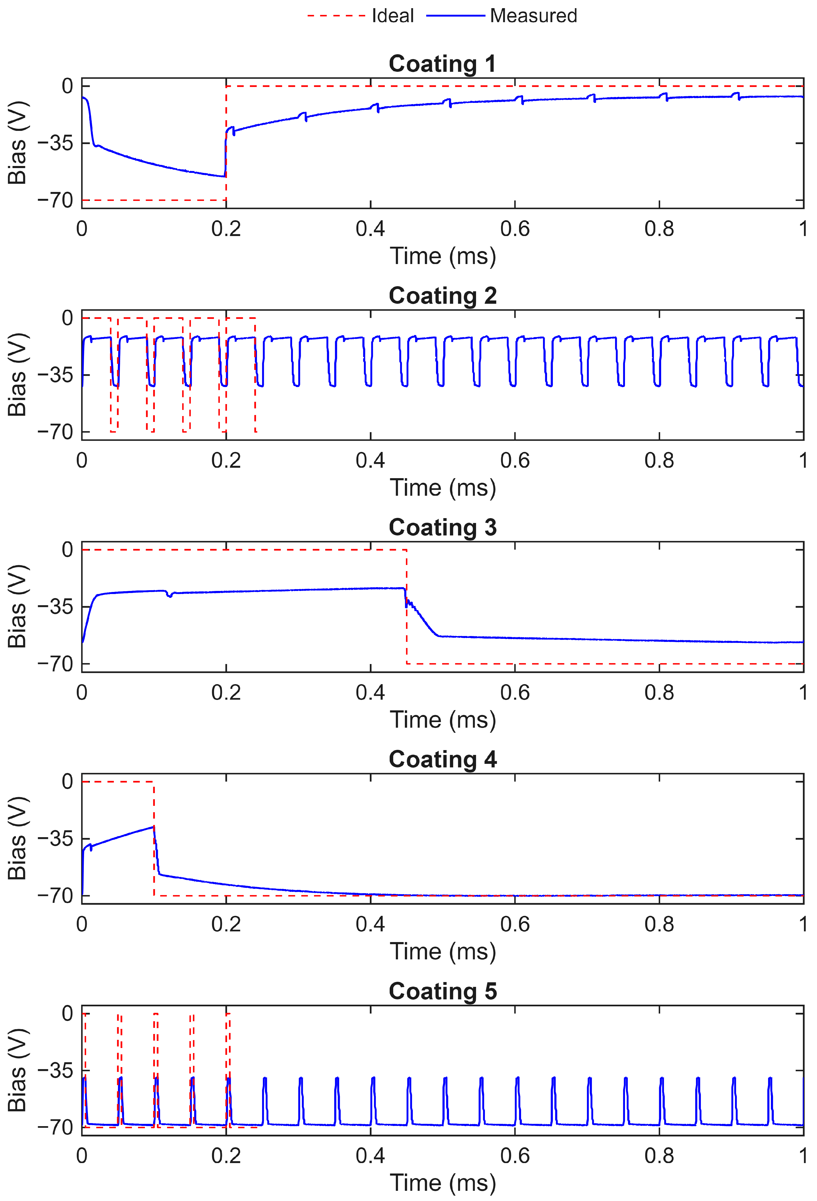
The electrical response of the deposition system was captured in real time using an oscilloscope connected to the substrate tower. As illustrated in Figure 1 (plotted on a 1 ms time scale to capture at least one complete cycle for all tested configurations), the measured bias voltage deviates significantly from an ideal programmed square wave. Because the power supply requires a finite transition time to switch between the base floating potential and the target bias (−70 V on-time), the actual waveform applied to the substrate is highly dependent on both the programmed duty cycle and frequency.
The dynamic response of the pulsed bias waveform is limited by a transition lag driven by the system’s inherent electrical impedance and the capacitive load of the plasma sheath [5,19]. At high duty cycles, the short off-time prevents the system from completely discharging, meaning the voltage does not return to the base floating potential. On the other side, at low duty cycles, the short on-time period ends before the system can fully charge, preventing the pulse from reaching the targeted bias (−70 V). These distortions are intensified when using a higher frequency, as it reduces the cycle time available for charging and discharging.
As shown in Table 2, the measured substrate bias exhibits a reduced amplitude compared to the programmed target values. For instance, at a 1 kHz frequency and 20% duty cycle (Coating 1), the extended off-time (800 µs) allows the substrate potential to discharge to −4.0 V. When the frequency is increased to 20 kHz at that same 20% duty cycle (Coating 2), the substrate only discharges to −11.0 V, and the significantly shorter on-time (10 µs) prevents the system from reaching the programmed bias, limiting the peak potential to only −42.3 V. Conversely, at a 90% duty cycle and 20 kHz (Coating 5), the short off-time (5 µs) prevents the substrate from discharging beyond −39.1 V before the subsequent pulse is triggered.
Although the pulse frequency restricts the voltage amplitude, the duty cycle remains the dominant factor governing the time-averaged substrate bias, which is commonly used as a first-order indicator of ion energy in industrial PVD systems. Table 3 compares the measured average bias against the ideal theoretical average for each configuration. As the average bias increases with higher actual duty cycles, the arriving ions possess higher kinetic energy. This enhances adatom mobility to drive the formation of a denser coating structure, simultaneously inducing higher hardness and compressive residual stress through atomic peening [9,43].
Despite variations in instantaneous ion energy across the pulse cycle, the time-average substrate bias serves as a practical indicator of relative ion energy input. Assuming a comparable ion flux under the stable plasma conditions of this study, the duty cycle emerges as the primary variable influencing the resulting microstructural and mechanical properties.

3.2. Phase Constitution and Microstructural Evaluation

To isolate the growth characteristics and morphological evolution of the AlTiN coatings from the influence of complex substrate geometries, the characterizations detailed in this section were performed on flat, mirror-polished cemented carbide coupons.
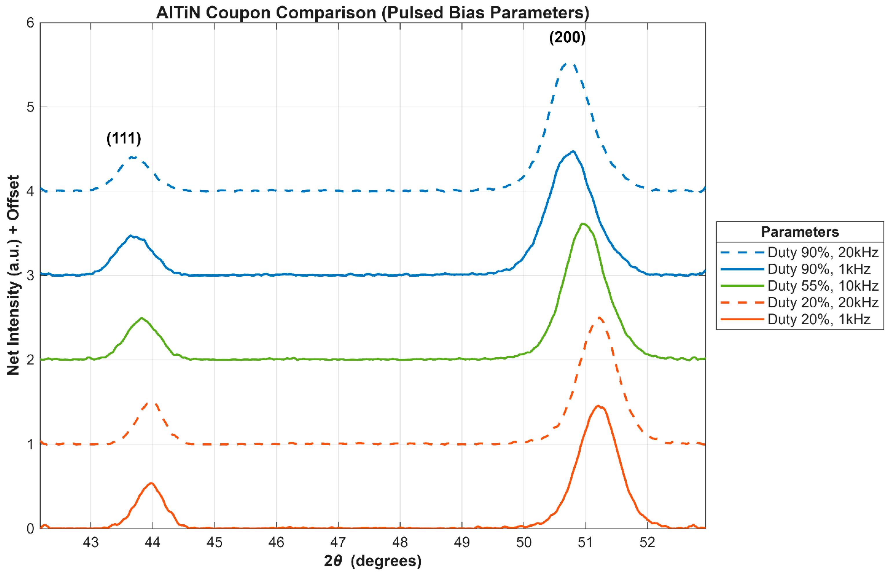
XRD was used to evaluate the crystallographic architecture of the AlTiN coatings. Phase analysis (Figure 2) confirmed the formation of a single-phase, face-centered cubic (fcc) solid solution across all samples, with a strong preferred growth orientation along the (200) plane relative to the (111) plane. As the deposition duty cycle was increased, the diffraction peaks shifted toward lower 2θ angles, alongside peak broadening. While peak broadening may also reflect changes in grain refinement, the dominant shift toward lower 2θ values with increasing duty cycle indicates lattice expansion associated with defect generation and compressive stress, reinforcing the higher ion bombardment argument discussed in Section 3.1.
Notably, the diffraction patterns for the 1 kHz and 20 kHz variants at equivalent duty cycles are nearly identical. This, combined with the electrical data in Section 3.1, provides strong evidence that pulse frequency has a negligible influence on the bulk phase constitution and lattice parameter changes. Consequently, a representative “Duty Cycle Series” was selected for high-resolution microstructural and composition characterization. This series, consisting of Coating 2 (20% duty), Coating 3 (55% duty, center point), and Coating 5 (90% duty), effectively isolates the dominant effect of time-averaged ion energy on the physical evolution of the coating.
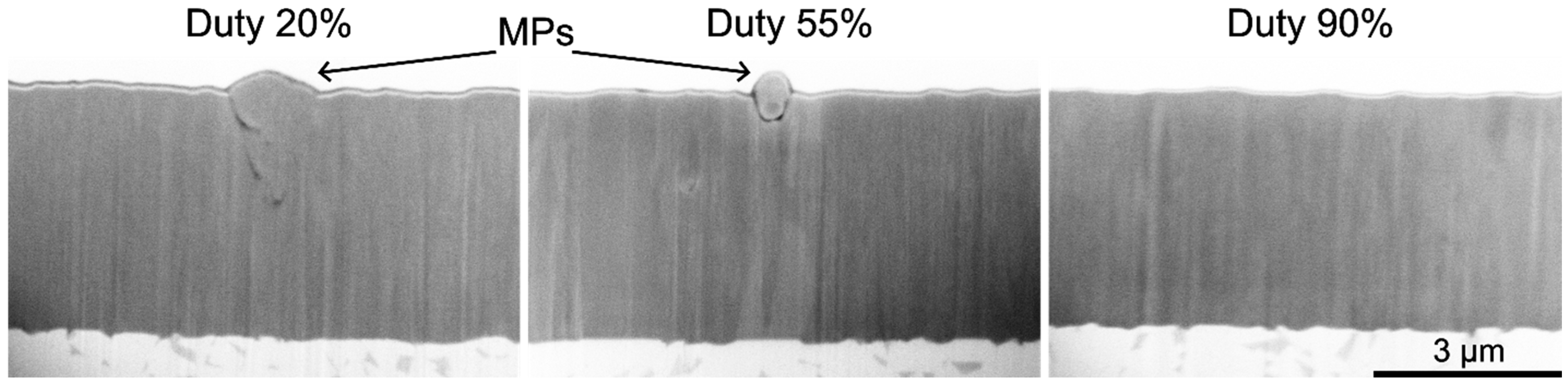
Surface topography and cross-sectional architecture of AlTiN coatings were evaluated using SEM coupled with FIB. The cross-sectional analysis (Figure 3) shows a fully dense microstructure well adhered to the cemented carbide substrate across the series. The micrographs for 20% and 55% duty illustrate the presence of macroparticles (MPs) near the surface of the coating. The distinct vertical lines extending through the film were identified as FIB-milling artifacts (curtaining) rather than coating defects, as these features extend uninterrupted across the substrate.
In addition to evaluating the coating morphology, the cross-sectional images were utilized to measure coating thickness. Coatings deposited at 20% and 55% duty cycles (low and intermediate energy levels) presented a consistent thickness of approximately 4.0 μm. In contrast, the coating deposited at 90% duty cycle (highest energy level) was slightly thinner at 3.7 μm. While this reduction might be associated with enhanced densification from increased ion bombardment, the 0.3 μm difference is well within the expected batch-to-batch variance and could be related to slight fluctuations in the deposition rate.
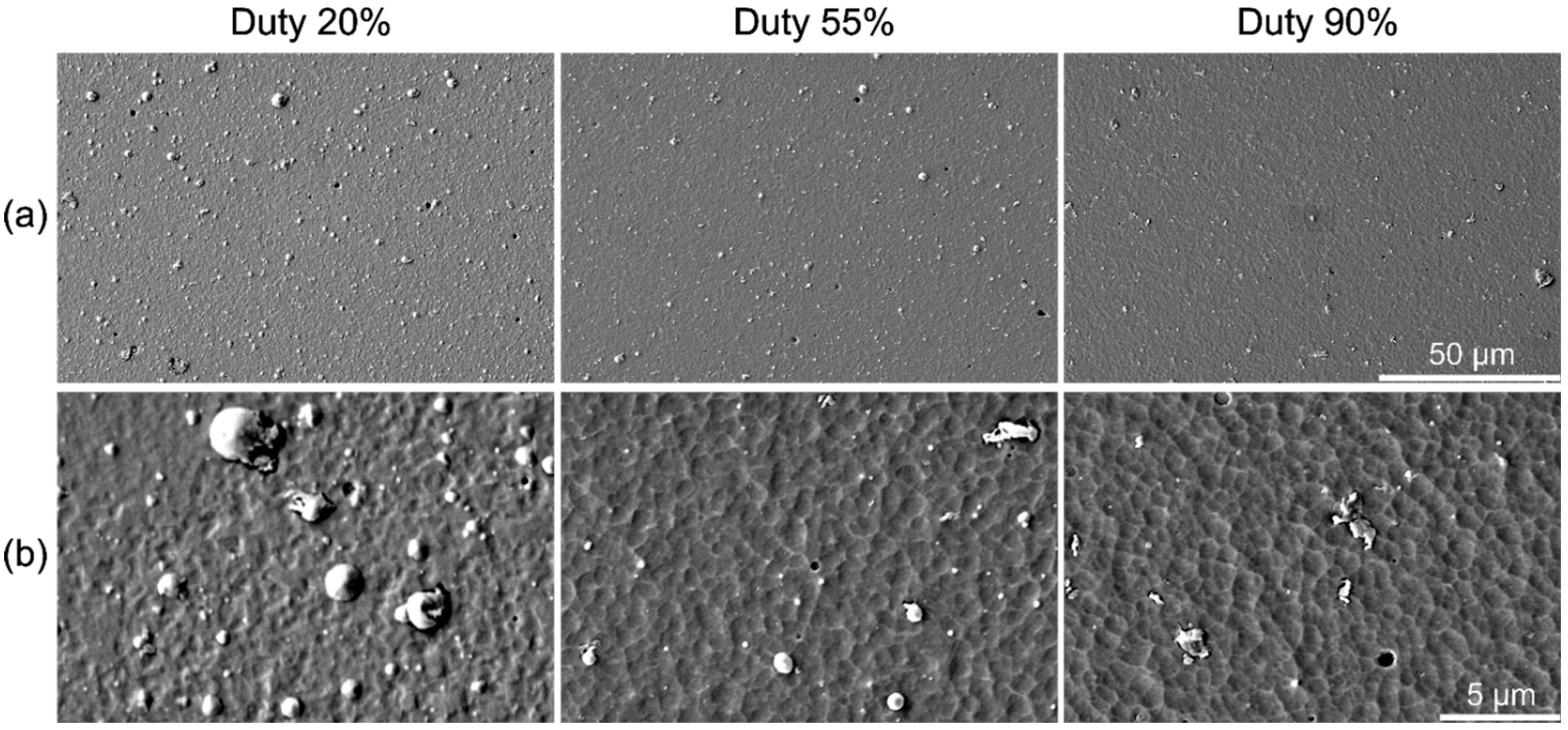
The surface topography (Figure 4), on the other hand, was significantly affected by the deposition energy. Although substrate bias parameters do not directly influence the initial generation of MPs at the cathodic source, they dictate their incorporation into the growing film. While this assessment is qualitative and intended to illustrate relative trends rather than establish a direct quantitative correlation, when using a 20% duty cycle, the surface visually appears more heavily populated with macroparticles, or droplets, that are characteristic of arc evaporation processes [5]. At this lower duty cycle, the reduced time-averaged substrate bias results in lower effective ion bombardment energy, limiting the resputtering and partial re-melting of metallic droplets during growth. As a result, a higher fraction of MPs remain embedded at or near the coating surface. Because these macroparticles often are predominantly metallic, they have a much lower hardness when compared to the surrounding nitride coating [44]. Under the extreme high-pressure and seizure conditions characteristic of machining, these droplets are rapidly sheared away. This localized material removal leaves behind a surface with craters and pinholes. These defects act as mechanical anchor points for workpiece material and create pathways for accelerated oxidation and diffusion [45]. When machining materials with high tendency for adhesion, this becomes even more critical. The localized adhesion at these sites can cause micro-chipping and eventual spallation of the surrounding coating.
As the duty cycle was increased to 55% and 90%, the apparent area density of macroparticles was significantly reduced. A primary hypothesis for this effect is that the higher energy ion bombardment effectively resputters these loosely adhered droplets during growth [46,47]. It’s important to note, however, that due to the limitations of this qualitative assessment, sub-micron macroparticles, beyond the resolution limit of the current micrographs, may still be present in the coating.
Apart from the droplet density and size distribution, all coatings exhibited a highly dense surface without the deep, open grain boundaries characteristic of typical Zone 2 columnar growth. Instead, the topography shows a fine, shallow structure, indicative of a Zone T morphology [48]. Had the deposition energy been significantly lower, the limited adatom mobility could have resulted in an underdense, porous coating, which would compromise the coating’s protective properties [48]. On the other hand, if the energy levels were too high, this could induce excessively high residual stresses, leading to poor adhesion and spontaneous spallation of the coating, or even shift to a dominant resputtering mode [49]. This confirms that within the deposition parameter range investigated, all coatings present a structural integrity adequate for comparative machining evaluation.
Elemental composition was determined via EDS analysis on the flat surfaces of the polished coupons. While the AlTi cathodic arc targets had a nominal composition of 60:40 at.%, the deposited coatings consistently exhibited a reduction in aluminum content, averaging approximately 55 at.% Al and 45% at.% Ti. This deviation relative to the target stoichiometry is a well-documented phenomenon in the reactive cathodic arc deposition of AlTiN and is primarily driven by two mechanisms [4]. First, the lighter Al atoms experience a wider scattering angle during transit through the plasma compared to the heavier Ti atoms, therefore reducing the effective Al flux reaching the substrate. Second, the intense ion bombardment induced by the substrate bias leads to preferential resputtering of the lighter Al atoms from the growing film surface.
Finally, to quantify the magnitude of the lattice distortion observed in the XRD patterns, macroscopic residual stresses were evaluated using the single-tilt sin2ψ method focused at the dominant (200) peak. The results of these calculations, and their correlation with micromechanical properties, are detailed in Section 3.3.

3.3. Micromechanical Properties

To evaluate the micromechanical properties of the AlTiN coatings, nanoindentation tests were performed on the surface of polished, AlTiN-coated cemented carbide coupons. The results for hardness (H) and reduced elastic modulus (Er), alongside the residual stress (σ) obtained from the XRD analysis, are summarized in Table 4.
To isolate the effects of pulsed bias parameters (frequency and duty cycle), a multiple regression analysis was conducted using a standard least-squares fit model in JMP Student Edition software, version 17. The statistical evaluation confirmed that bias frequency had no significant main effect on any of the measured properties (p > 0.05). While modulating the frequency between 1 kHz and 20 kHz changes the absolute duration of individual pulses, it does not directly alter the cumulative on-time of the power supply. Consequently, the time-averaged ion energy remains essentially constant across varying frequencies at a fixed duty cycle.
Beyond that, nanoindentation results showed that the reduced elastic modulus (Er) remained statistically invariant across all deposition conditions, with a stable value of approximately 400 GPa. While properties like hardness and yield strength are highly sensitive to processing-induced defects, grain sizes, and residual stress, the elastic modulus is an intrinsic material property governed primarily by interatomic bond strength and phase composition [50]. Because all coatings were deposited utilizing identical AlTi (60:40 at.%) targets and maintained a consistent stoichiometry of 55:45 at.% confirmed by EDS, the fundamental bonding architecture remained the same. Therefore, the Elastic Modulus was not influenced by the applied bias duty cycle.
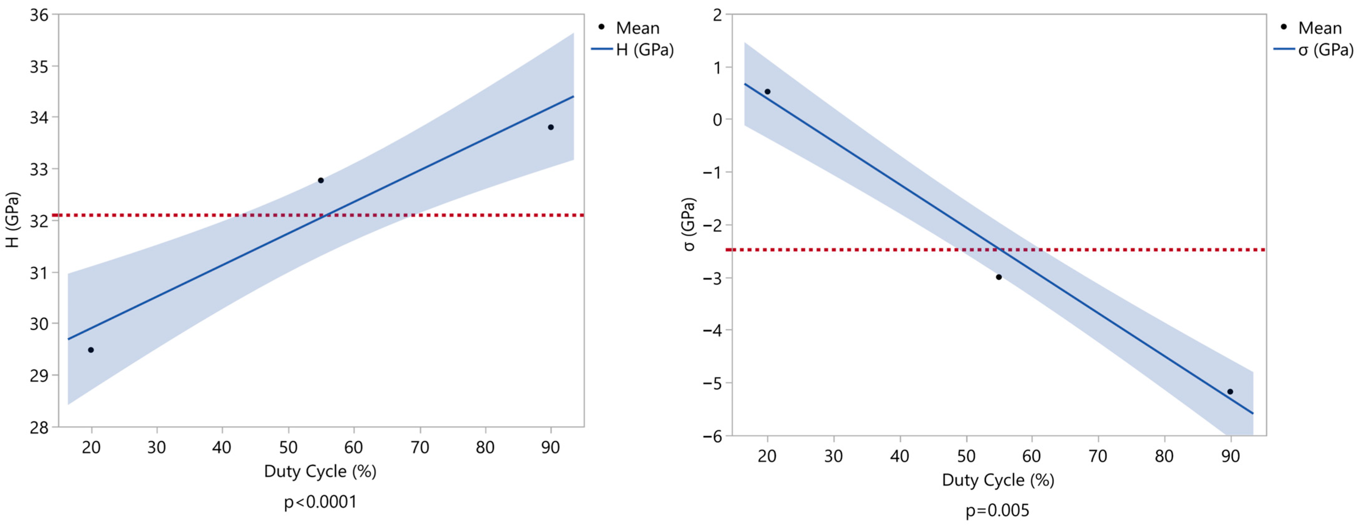
In contrast, the duty cycle presented as a highly significant main effect (p < 0.01) influencing both the coating hardness and residual stress. As shown in Table 4, deposition at a low duty cycle (20%—Coatings 1 and 2) generated a coating with a slightly tensile residual stress of approximately +0.5 GPa. Increasing the duty cycle to an intermediate level (55%—Coating 3) shifted the stress to a compressive state of −3.0 GPa, while a high duty cycle (90%—Coatings 4 and 5) resulted in even higher compressive residual stresses, reaching up to −5.2 GPa. This transition from a near-neutral/tensile state to a highly compressive state shows the effect of atomic peening on macroscopic stresses as ion bombardment energy increases.
As shown by the leverage plot (Figure 5), the coating hardness is directly correlated with the residual stress state. The accumulation of compressive stress caused a statistically significant increase in hardness, rising from approximately 29.4 GPa at the lowest duty cycle (20%) to a maximum of 33.9 GPa at the 90% duty cycle. This finding validates the initial hypothesis: while frequency alters the bias pulse shape, the duty cycle is the primary driver of the energetic ion–surface interactions that dictate the final mechanical state of the AlTiN film.
It is important to note that these quantitative stress measurements were performed on flat, mirror-polished coupons. On actual cutting tools, the localized residual stress fields at sharp cutting edges and flute valleys will inevitably differ due to the non-uniform ion flux and plasma sheath concentration around complex geometric features [16]. Nevertheless, the fundamental mechanism remains consistent; higher duty cycles generate substantially higher compressive stresses by maximizing the time-averaged kinetic energy of the arriving ions. This establishes a critical trade-off between the high hardness desired for wear resistance and the structural integrity required for sharp tool geometries.

3.4. Edge Integrity and Geometric Effects

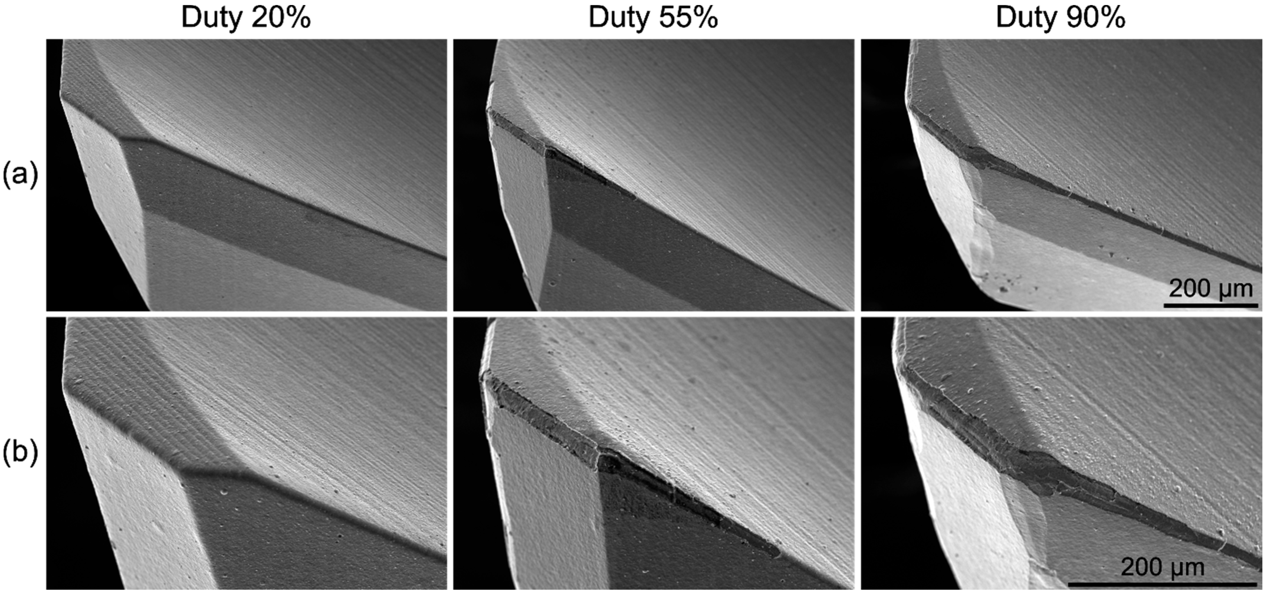
Prior to machining tests, the influence of varying deposition energies on the structural integrity of the coated tools was evaluated. The AlTiN coatings were deposited onto two distinct tool geometries: solid carbide endmills (Kennametal 3CH0400MS012A) and cemented carbide turning inserts (Widia CNMG 120408 FS K313). SEM analysis revealed that the applied duty cycle had a direct impact on coating integrity, specifically localized at the sharp cutting edges of the endmills. As illustrated in the SEM micrographs (Figure 6), high-energy depositions (55% and 90% duty cycles) resulted in spontaneous coating delamination and inadequate corner coverage. Conversely, the low-energy 20% duty cycle produced a uniformly well-adhered coating across the entire endmill geometry.
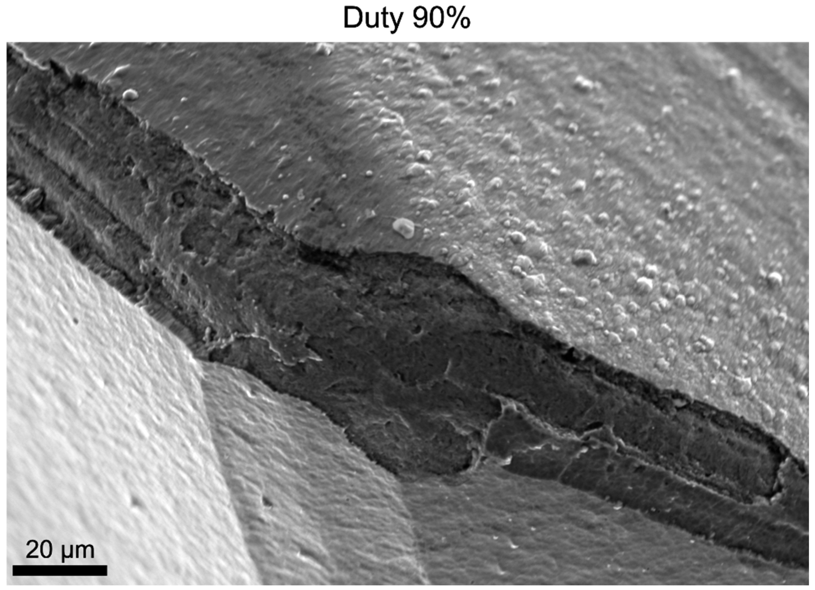
Higher magnification SEM evaluation of the 90% duty cycle endmill (Figure 7) shows that while the coating remained well adhered to the planar flank and rake faces, the intense high-energy deposition severely damaged the cutting edge, fundamentally changing the initially designed edge radius.
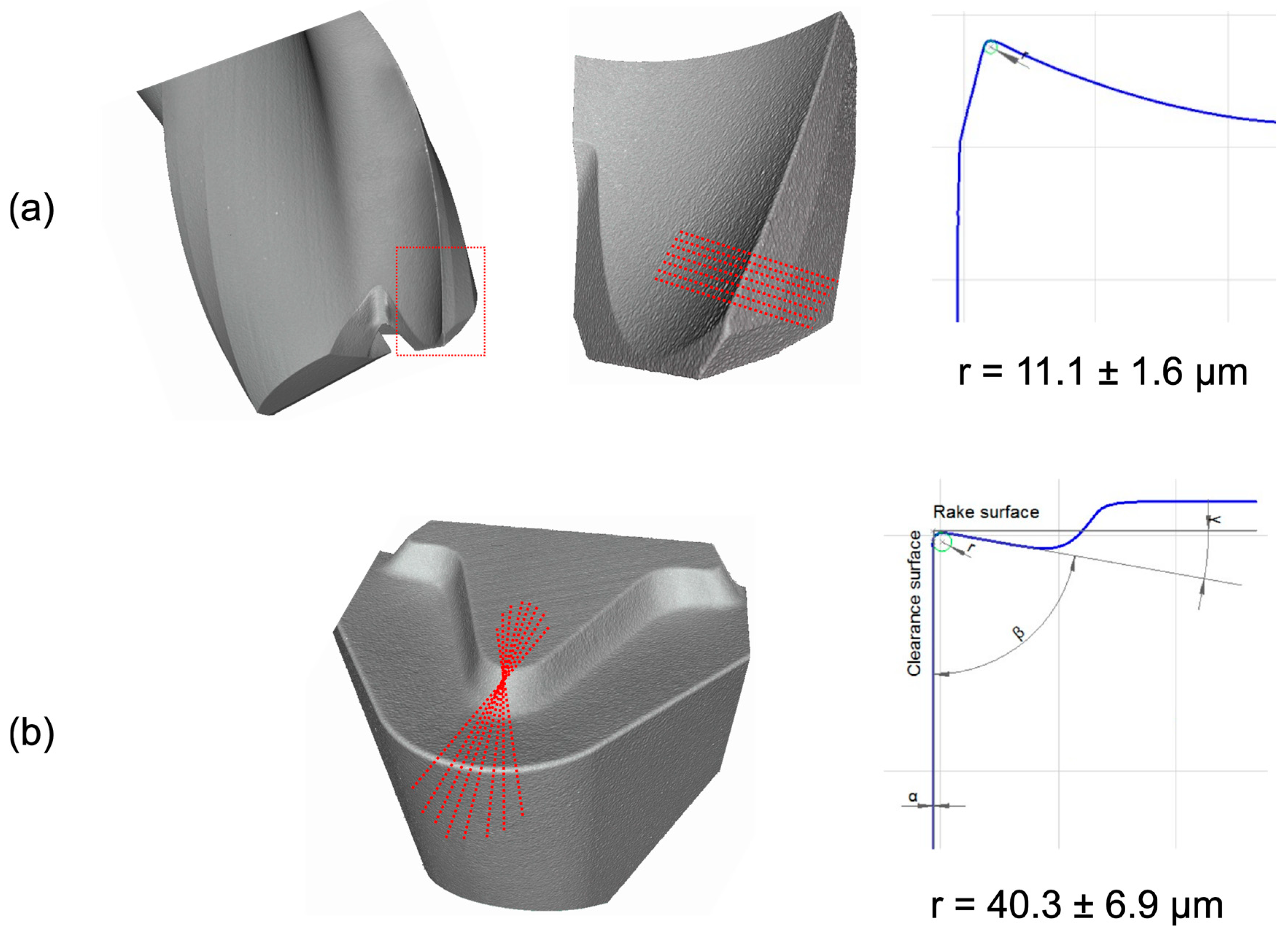
These edge integrity issues were not observed on the turning inserts across any of the tested duty cycles. This is attributed to the distinct geometric profile of the inserts, which have a significantly less acute wedge angle (macro-geometry) alongside a substantially larger cutting-edge radius (micro-geometry). To quantify this geometric difference, 3D optical profilometry was performed using an Alicona system. As shown in Figure 8, the turning inserts exhibited an average edge radius of 40.3 µm, nearly four times larger than the 11.1 µm radius on the solid carbide endmills.
The localized failure observed on the sharper endmill edges is likely driven by three complementary factors. First, the Antenna Effect causes the electric field lines to concentrate at the sharp cutting edges [5,17]. This significantly increases both the local ion flux and the average kinetic energy of the arriving ions, driving the local residual stress beyond the coating’s cohesive strength at the cutting edge. Second, the acute geometry of the endmill edge induces a non-uniform angle of incidence. While ions arrive primarily normal to flat surfaces, sharp edges are subjected to ion bombardment from a wide angular range. This is critical because the resputtering yield increases as the angle deviates from the surface normal [16,51]. Under high-energy conditions, this effectively removes portions of the coating during growth. Third, the significantly higher surface-to-volume ratio of small solid endmills compared to the turning inserts limits their capacity for heat dissipation. This leads to a higher localized temperature rise at the cutting edge, potentially intensifying thermal-mismatch stresses upon cooling.
Because structural integrity of the coatings on the turning inserts remained visually indistinguishable at both the lowest (20%) and highest (90%) duty cycles, they represent the ideal tool geometry to evaluate intrinsic machining performance. Utilizing these inserts allows for a comparative analysis of the distinct coatings’ wear behavior, isolating the true machining performance from the premature spontaneous edge failure induced by the deposition process.

3.5. Machining Performance

To evaluate machining performance, turning tests were performed on a Nakamura-Tome SC450 turning center using SS304 as the workpiece material. Due to its low thermal conductivity and high work-hardening rate, SS304 tends to concentrate intense thermal energy directly at the tool’s cutting edge, creating an aggressive tribological and thermal environment [52], particularly at high cutting speeds. Initially, an uncoated control insert of identical geometry was tested. The cutting conditions were so severe that the tool suffered catastrophic failure in under 5 s, showing that an uncoated substrate is completely unsuitable for these parameters. Next, three AlTiN-coated inserts deposited at 20%, 55%, and 90% duty cycle were tested. For each coated variant, two independent turning tests were performed under identical cutting conditions.
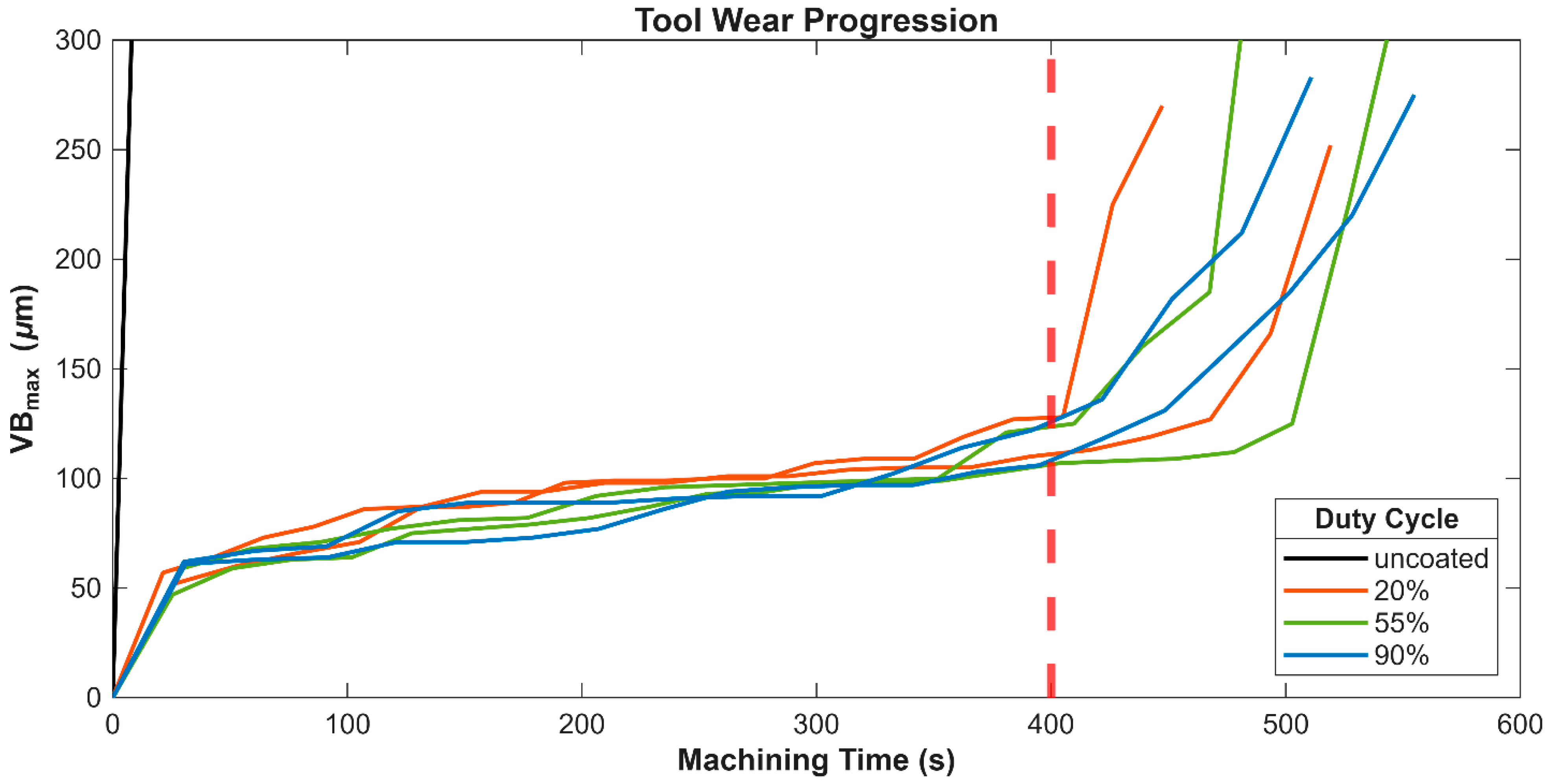
At room temperature, the coating exhibiting the highest hardness and compressive stress (90% duty cycle) is theoretically expected to provide superior resistance against abrasive wear mechanisms, thereby extending tool life. However, the progression of tool wear, shown in Figure 9, reveals a similar performance across all tested coatings. Because conventional statistical descriptors are not meaningful for a sample size of two, the individual wear trajectories for each replicate are presented. For the first 400 s of machining, wear progression remained stable and nearly identical regardless of the coating. After this stable phase, between 400 and 550 s, the wear rate became more unstable, growing rapidly toward the failure criteria. Given the variance between the replicates during this unstable phase, no significant difference in terms of tool life can be established considering the subset tested. Nevertheless, these tests highlight the critical protective role of the AlTiN coatings, regardless of the specific deposition parameters used.
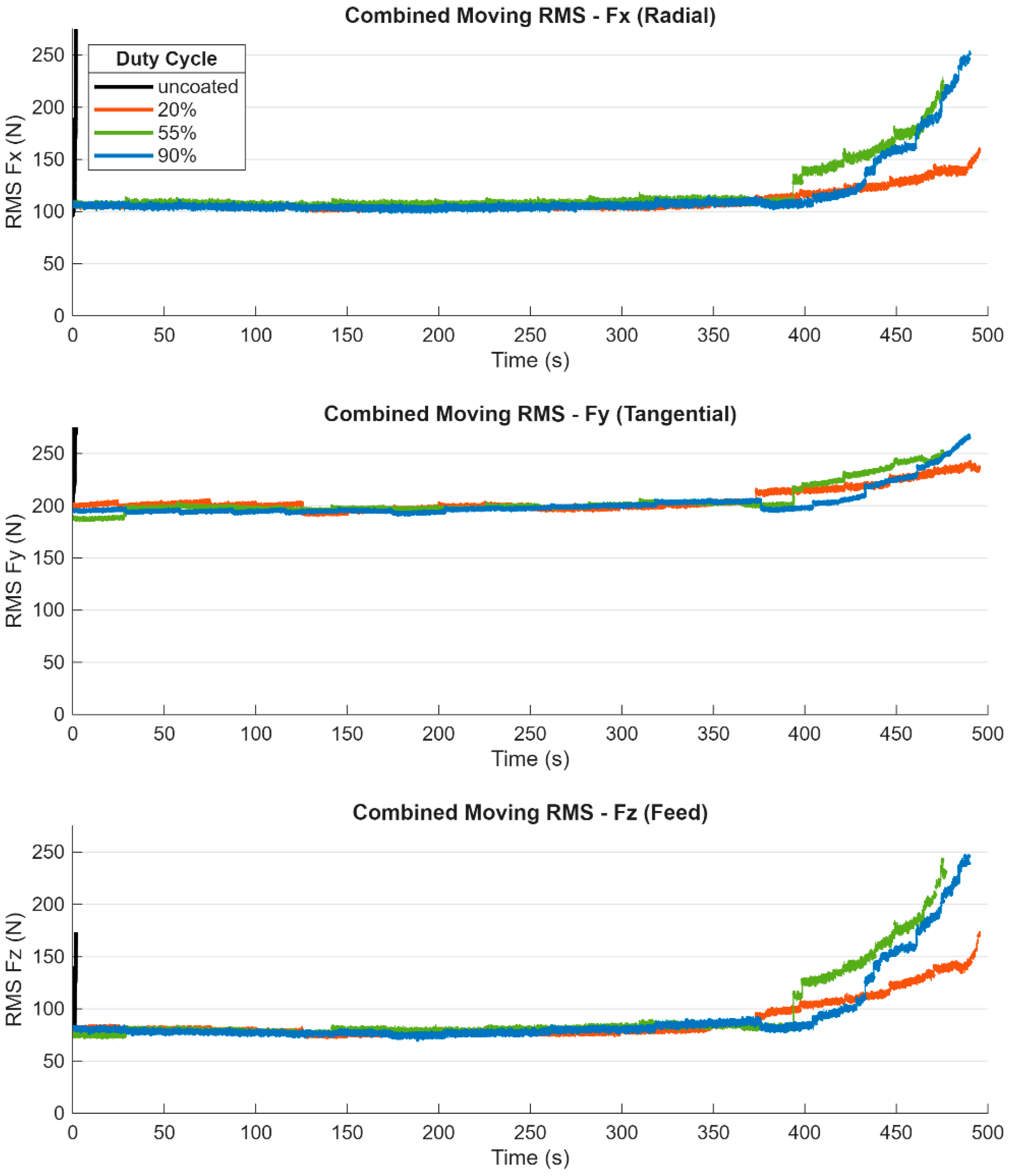
The tool wear progression presents a good correlation with the cutting force data. As shown in the moving root-mean-square (RMS) force plot (Figure 10), the principal cutting forces (Fx, Fy, Fz) exhibited nearly identical profiles across all coated tools throughout the stable cutting phase. Consistent with the flank wear measurements, the RMS forces remained relatively steady for the first 400 s before showing a rapid increase. This spike in cutting forces mirrors the start of unstable wear, indicating the rapid degradation of the cutting edge.
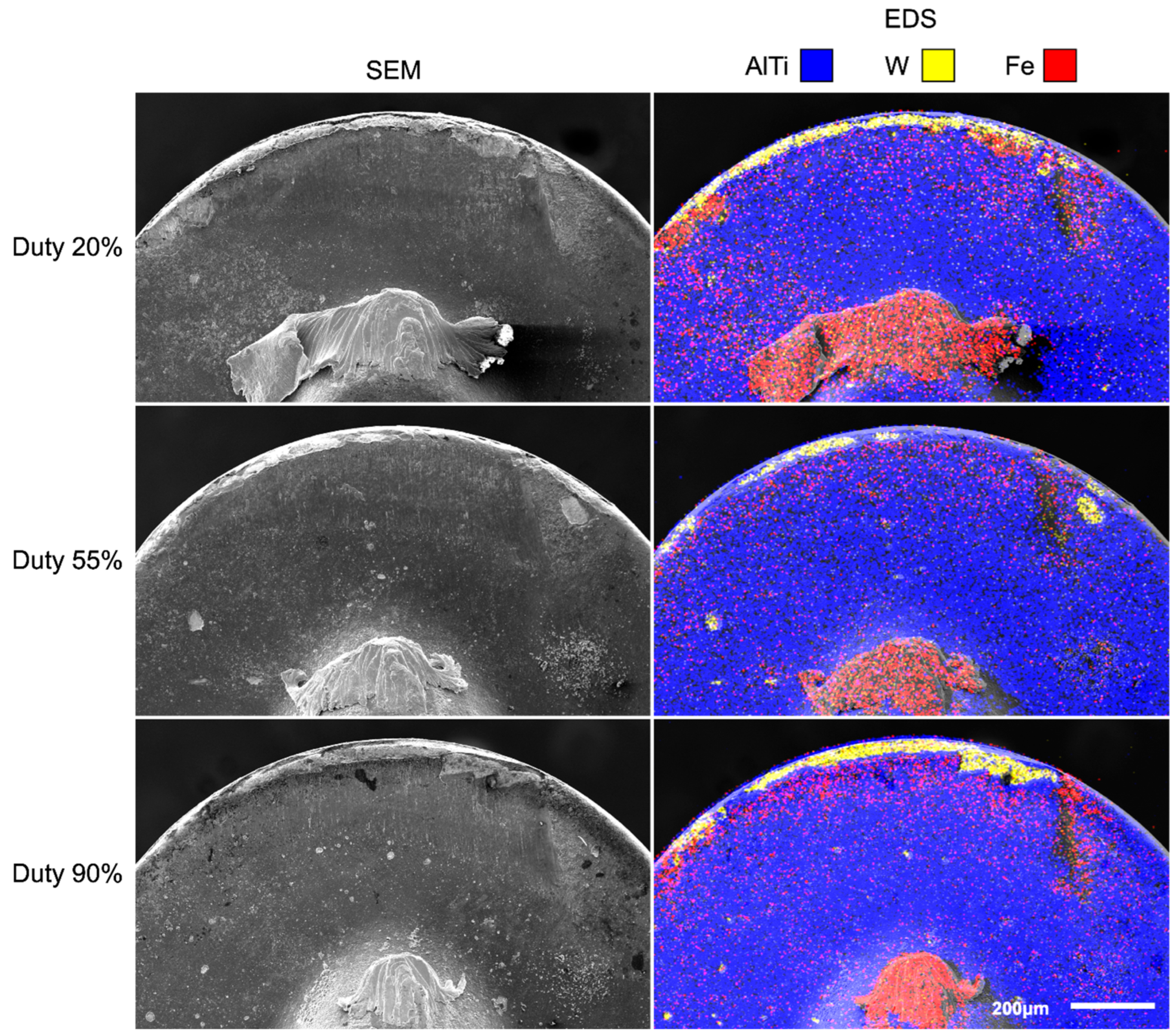
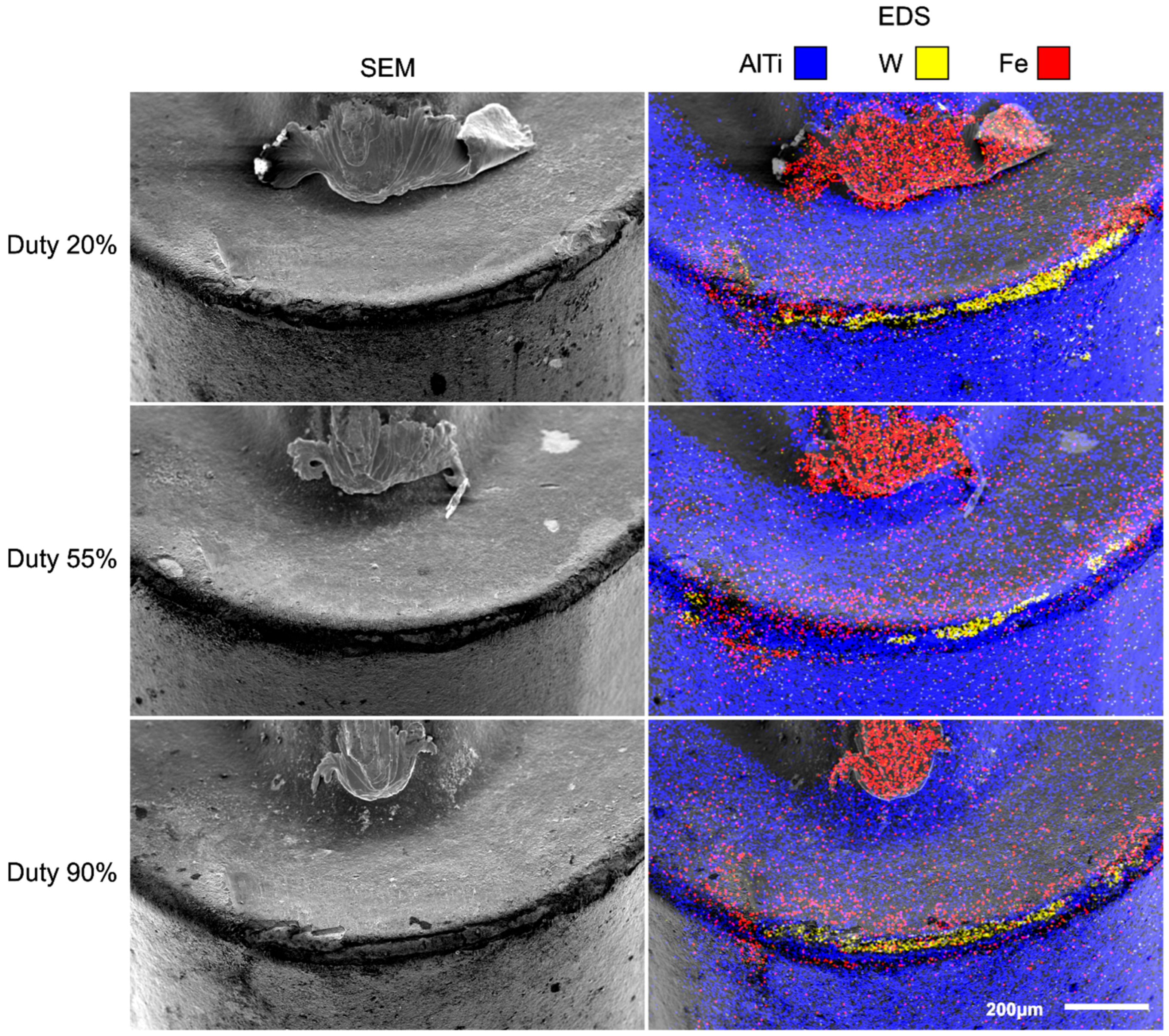
The wear mechanisms were evaluated across all coated tools at various machining intervals. SEM and EDS were used after 30 s of machining to assess the initial tool wear progression at the cutting edge (Figure 11) and rake face (Figure 12). The images show a good adhesion of the AlTiN coating to the substrate on both the rake and flank faces. This stability corroborates the uniform and steady cutting forces observed in the moving RMS data.
Figure 11 shows the cutting-edge morphology and EDS mapping. As expected, minor substrate exposure (indicated by the yellow tungsten signal) is visible at the very edge, alongside some adhered material (red iron signal), mainly on the chip breaker section but also small amounts on the rake surface and near the cutting edge. Comparing the tools, the one coated at a 55% duty cycle exhibited the least substrate exposure at the cutting edge, highlighting the critical role of deposition parameters during early stages of tool wear. The rake face evaluation (Figure 12) corroborates the observations from the edge analysis. The coating deposited at a 55% duty cycle exhibits superior adhesion near the cutting zone, while the others (20% and 90%) show comparable levels of substrate exposure on the rake face. Despite these localized differences, flank wear progression at the 30 s mark remains minimal and consistent across all coated tools.
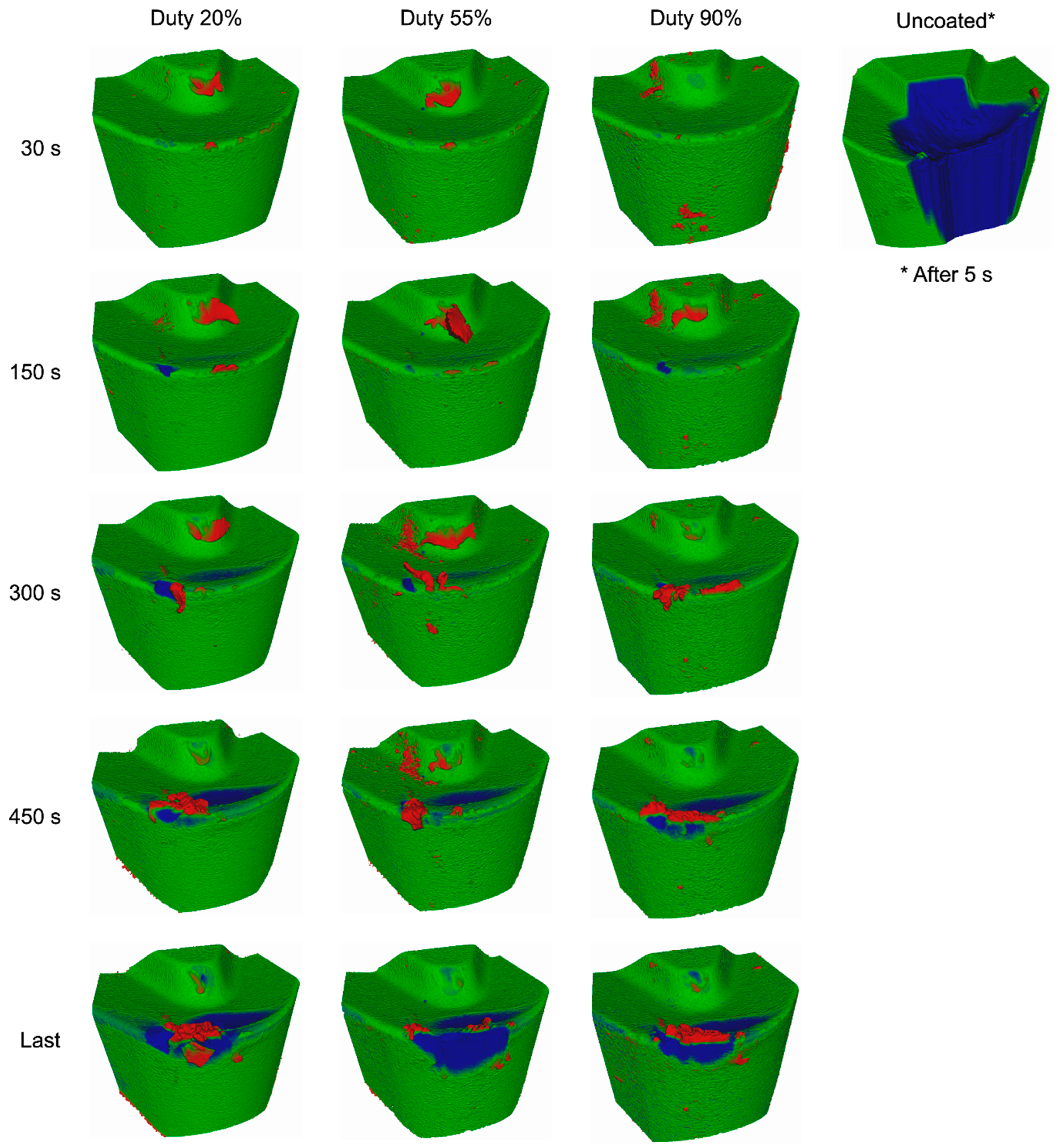
To quantify volumetric wear progression, 3D optical profilometry (Alicona) was performed (Figure 13). Scans of new tools were compared against scans taken in different machining intervals, from 30 s to the end of the tool life. This generates a topographical map showing regions above and below the original reference surface. Blue regions indicate material loss while red regions show material build up (adhered material), and features within ±5 µm from the original new tool are shown in green.
The analysis immediately confirms that the uncoated carbide tool is unsuitable for this application, experiencing catastrophic failure with severe edge deformation and material loss within just 5 s of machining. For the AlTiN-coated tools, volumetric wear at 30 s is within the ±5 µm tolerance, with only minor signs of adhesion near the edge and chips getting stuck in the chip breaker section.
By 150 s, signs of notch wear start becoming visible, more pronounced on the 20% and 90% duty cycle tools. At 300 s, the 55% and 90% show similar performance. The 20% tool at this stage shows a larger crater wear zone and a more significant notch, though the flank wear remains controlled, keeping all the tools within the stable regime. This accelerated wear in the 20% tool can likely be attributed to increased adhesion and diffusion mechanisms. The apparent higher density of macroparticles on this coating could generate more nucleation sites for mechanical anchoring of chips and material diffusion, promoting earlier localized wear. Despite the large cratering, the consistent RMS force data and comparable flank wear measurements indicate that the overall integrity of the tools was still maintained.
Beyond 400 s, tool wear intensifies. Cratering expands across all tools, remaining more severe for the 20% tool, and flank wear becomes more visible. The 55% duty cycle tool continues to exhibit the lowest wear levels. While optical 2D measurements of flank wear remain similar across all tools (as shown in the tool life curves), 3D volumetric analysis shows that the 55% tool retains slightly more of its original geometry.
All tools remain functional at this stage, but degradation starts to accelerate significantly, entering an unstable phase. During the final passes (from 450 to 550 s) intense adhesion and rapid increase in tool forces lead to unpredictable wear patterns. Because this failure phase is characterized by a more chaotic adhesion and fracture mechanics rather than a steady state wear, the final volumetric differences do not necessarily indicate that one coating definitively outperforms the others. For instance, the 55% duty cycle coated tool, despite presenting the smallest level of volumetric tool wear throughout the entire test, had a sharper increase in wear volume on the last passes. Given the similar tool life for all variants tested, the performance of all tools is likely equivalent.
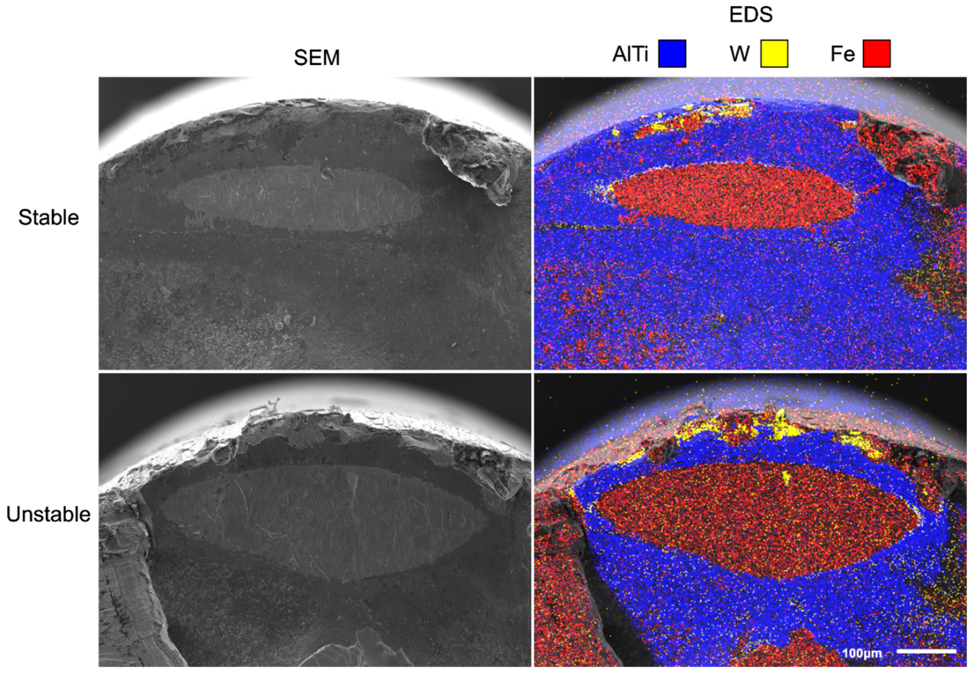
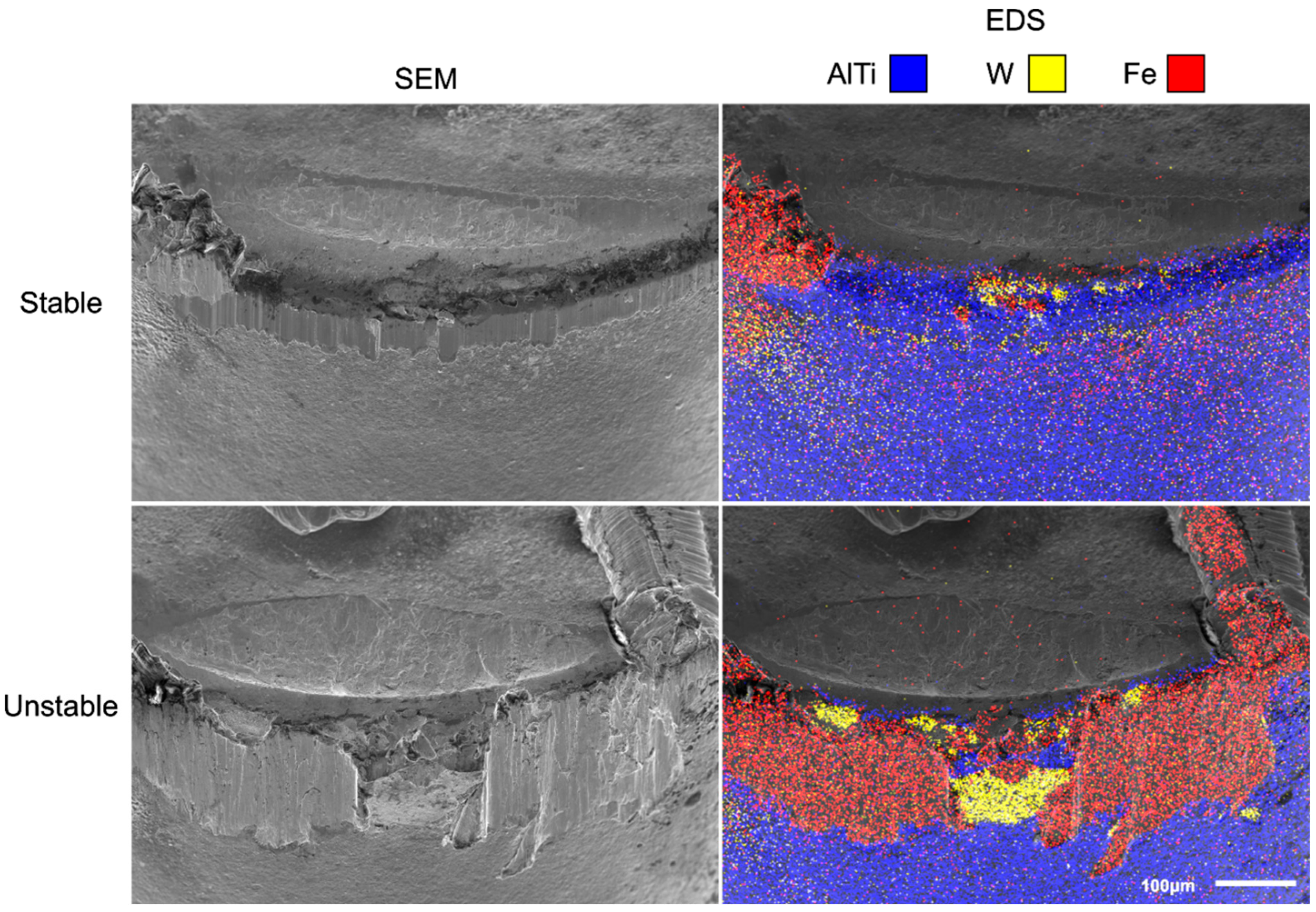
Because the wear progression was consistent across all AlTiN-coated tools, representative SEM/EDS images of a single tool (the 55% duty cycle variant) were selected for detailed analysis of the wear mechanisms. Figure 14 and Figure 15 illustrate the morphology and composition of the flank and rake faces, respectively, under two conditions: a stable mid-life cutting regime (300 s) and the unstable regime observed near the tool’s final pass.
While flank face has a dominant role in overall machining stability, the rake face resists the most severe thermal loads and prolonged contact, especially at the seizure zone. Across all coatings tested, even in the stable mid-life condition, significant crater wear is already visible. The corresponding EDS map shows that this initial crater consists of exposed cemented carbide substrate (W, yellow) that has been rapidly filled and covered by adhered workpiece material (Fe, red). By the final passes (unstable region), this cratering is intensified. This localized wear is driven by the extreme temperatures and chemical affinity between the sliding SS304 chips and the tool surface. Once the protective AlTiN coating (AlTi, blue) is thermally degraded and stripped away, the cemented carbide substrate is directly exposed to the chip flow. This facilitates adhesion and rapid atomic diffusion between the chip and the tool, accelerating the growth of the crater.
Despite this severe diffusive wear on the rake face, the cutting mechanics can often tolerate cratering for an extended period. The primary cause for process instability often lies on the flank face, which governs the interaction between the tool and the highly stressed, newly machined workpiece surface. The AlTiN coating acts as a critical tribological barrier, providing the hot hardness and lubricity required to maintain this stability.
The EDS elemental maps in Figure 14 clearly illustrate the effects of flank surface coating removal in machining performance. During the stable regime, the AlTiN coating (AlTi, blue) remains predominantly preserved across the flank face. While minor, localized exposure of the tungsten carbide substrate (W, yellow) is visible, workpiece adhesion (Fe, red) is largely restricted to a narrow built-up edge. Conversely, the unstable regime presents a very different morphology. A significant portion of the coating has been removed, exposing a large area of the underlying substrate. This exposed cemented carbide region is accompanied by a massive workpiece material adhesion, shown by the dense concentration of iron (red) overlapping the areas of coating failure.
This severe adhesion triggers an accelerated unstable wear, causing the cutting mechanics transition from a more efficient shearing to intense rubbing and ploughing. Because SS304 is a highly ductile alloy prone to work-hardening, the workpiece material continuously extrudes and welds to the exposed substrate, forming a built-up edge (BUE). The cyclical adhesion and sliding of the workpiece material causes severe attrition wear. As the BUE is repeatedly sheared away during cutting, it removes fragments of the tool’s carbide substrate, and these fractured hard particles are then dragged down the flank face. Attrition thus acts as a continuous source of hard particles that facilitate secondary three-body abrasion, causing the deep irregular grooves observed in the SEM images. Ultimately, this destructive cycle of attrition-induced abrasion, combined with the thermal softening caused by high-friction rubbing, drives the process into total instability and primary tool failure.
Despite significant initial differences in room-temperature hardness and residual stress states, tool life and wear progression were remarkably similar across all evaluated AlTiN coatings. Two primary hypotheses are proposed to explain this behaviour during the high-speed, dry turning of SS304.
First, because the tool integrity in this application depends on resisting both high-temperature abrasion and subsequent severe adhesion, initial room-temperature hardness is not the primary determinant of overall machining performance. Instead, hot hardness and thermo-chemical stability dictate the tool life. In processes dominated by these wear mechanisms, such as the dry machining of ductile SS304, the high-temperature chemical stability and oxidation resistance of the tool surface are the defining metrics. Because all coatings shared the same AlTiN elemental composition, they exhibit nearly identical chemical affinity with the workpiece, and comparable resistance to diffusive wear at high temperatures. Notably, even the higher macroparticle density observed in the 20% duty cycle coating was insufficient to compromise its overall machining performance. These coatings defects are considered a secondary, local effect that may act as initiation sites that accelerated localized cratering, largely confined to the more forgiving rake face. As long as the AlTiN remained attached on the critical flank face, the stability of the process was maintained.
Secondly, the similar performance may be attributed to the rapid thermal relaxation of the coatings’ initial residual stress states during the machining process. While in situ high-temperature mechanical or structural characterizations were not performed in this study, it is hypothesized based on established literature for PVD nitride coatings [53,54,55] that the extreme, localized thermal loads generated at the cutting zone can provide sufficient activation energy to drive relaxation mechanisms, such as defect annihilation. Consequently, it is assumed that this intense heat effectively relieves a portion of the highly compressive residual stresses, such as the −5.2 GPa state generated by the high energy 90% duty cycle deposition. As a result, the initial differences in room-temperature hardness likely became negligible at operational temperatures, suggesting that the hot hardness of all three coatings effectively converged under the thermal loads of the cutting process.
In summary, while it is standard practice to engineer PVD coatings with some compressive residual stress to maximize room-temperature hardness and crack resistance, the operational thermal environment ultimately dictates the coating performance in high-speed machining. In this context, the low-energy 20% duty cycle represents an optimal overall strategy, particularly for coating a diverse range of tool geometries. It delivers equivalent high-temperature machining performance while maintaining a significant lower residual stress state. This is critical for successfully coating complex tools with sharp edge radii, as it prevents the localized delamination associated with excessive ion bombardment. Consequently, utilizing lower-energy parameters serves as an effective, and sometimes necessary, strategy for balancing edge integrity and overall tool life.

4. Conclusions

This study investigated the effects of pulsed substrate bias parameters (duty cycle and frequency) on the electrical response, microstructure, and machining performance of cathodic arc PVD AlTiN coatings. The key conclusions are:
  • Electrical Response and Ion Energy: System electrical impedance and capacitive loading cause the actual bias waveform to deviate significantly from the programmed parameters. Duty cycle is the dominant variable controlling the time-average substrate bias, whereas pulse frequency (within the 1 to 20 kHz range) has a negligible effect on the overall bias, hardness and residual stress.
  • Microstructure and Hardness: All coatings exhibited a highly dense surface indicative of Zone T-type morphology. Room-temperature hardness increased from 29.4 GPa to 33.9 GPa as the duty cycle was raised from 20% to 90%, while the elastic modulus remained largely unchanged.
  • Residual Stress and Edge Integrity: The 90% duty cycle induced a high compressive residual stress state (−5.2 GPa), contrasting with the slightly tensile state (+0.5 GPa) observed at 20%. While beneficial on flat surfaces, this highly compressive residual stress caused catastrophic delamination on sharp tool geometries (solid endmills) due to localized ion flux concentration.
  • Thermal relaxation and Machining Performance: During high-speed dry turning of SS304, all evaluated AlTiN-coated turning inserts exhibited similar wear progression, cutting forces, and failure mechanisms. It is hypothesized that the extreme thermal loads at the tool–chip interface likely provided sufficient activation energy to relieve the initial compressive residual stresses, causing the operational hot hardness of the coatings to converge. Consequently, the coating’s high-temperature thermo-chemical stability proved to be more critical than their initial room-temperature hardness.
Overall, designing PVD coatings purely to maximize room-temperature hardness is an incomplete and potentially detrimental strategy for cutting tools. Lower-energy deposition parameters, such as a 20% duty cycle, provided equivalent machining performance for turning inserts while preserving the structural integrity of complex, sharp-edge tools.

Author Contributions

Conceptualization, V.S.; Methodology, V.S.; Validation, J.K. and S.V.; formal analysis, V.S.; Investigation, V.S.; resources, J.K. and S.V.; Writing—original draft preparation, V.S.; writing—review and editing, V.S., J.K. and S.V.; supervision, S.V. All authors have read and agreed to the published version of the manuscript.

Funding

We acknowledge the support of the Natural Sciences and Engineering Research Council of Canada (NSERC), funding reference numbers RGPIN-2024-06690 and ALLRP 597438-24, and the support of the Ontario Ministry of Colleges, Universities, Research Excellences and Security (MCURES), funding reference number ORF RE012-030.

Institutional Review Board Statement

Not applicable.

Informed Consent Statement

Not applicable.

Data Availability Statement

All data are presented in the current manuscript. For further queries, communicate with the corresponding author.

Conflicts of Interest

Author Joern Kohlscheen was employed by the company Kennametal (Germany) GmbH. The remaining authors declare that the research was conducted in the absence of any commercial or financial relationships that could be construed as a potential conflict of interest.

Abbreviations

The following abbreviations are used in this manuscript:
PVDPhysical Vapor Deposition
SEMScanning Electron Microscopy
EDSEnergy-Dispersive X-ray Spectroscopy
PFIBPlasma Focused Ion Beam
FIBFocused Ion Beam
MPMacroparticle

References

  1. Shawn, M.C. Metal Cutting Principles, 2nd ed.; Oxford University Press: New York, NY, USA, 2005; 759p. [Google Scholar]
  2. Diniz, A.E.; Machado, Á.R.; Corrêa, J.G. Tool wear mechanisms in the machining of steels and stainless steels. Int. J. Adv. Manuf. Technol. 2016, 87, 3157–3168. [Google Scholar] [CrossRef]
  3. Bobzin, K. High-performance coatings for cutting tools. CIRP J. Manuf. Sci. Technol. 2017, 18, 1–9. [Google Scholar] [CrossRef]
  4. PalDey, S.; Deevi, S.C. Single layer and multilayer wear resistant coatings of (Ti,Al)N. Mater. Sci. Eng. A 2003, 342, 58–79. [Google Scholar] [CrossRef]
  5. Anders, A. Cathodic Arcs: From Fractal Spots to Energetic Condensation. In Springer Series on Atomic, Optical, and Plasma Physics; Springer: New York, NY, USA, 2008. [Google Scholar]
  6. Anders, A. A review comparing cathodic arcs and high power impulse magnetron sputtering (HiPIMS). Surf. Coat. Technol. 2014, 257, 308–325. [Google Scholar] [CrossRef]
  7. Lieberman, M.A.; Lichtenberg, A.J. Principles of Plasma Discharges and Materials Processing, 2nd ed.; John Wiley & Sons: Hoboken, NJ, USA, 2005. [Google Scholar]
  8. Alhafian, M.R.; Chemin, J.-B.; Fleming, Y.; Bourgeois, L.; Penoy, M.; Useldinger, R.; Soldera, F.; Mücklich, F.; Choquet, P. Comparison on the structural, mechanical and tribological properties of TiAlN coatings deposited by HiPIMS and Cathodic Arc Evaporation. Surf. Coat. Technol. 2021, 423, 127529. [Google Scholar] [CrossRef]
  9. Salamania, J.; Johnson, L.; Schramm, I.; Calamba, K.; Boyd, R.; Bakhit, B.; Rogström, L.; Odén, M. Influence of pulsed-substrate bias duty cycle on the microstructure and defects of cathodic arc-deposited Ti1-xAlxN coatings. Surf. Coat. Technol. 2021, 419, 127295. [Google Scholar] [CrossRef]
  10. Zhang, G.P.; Gao, G.; Wang, X.; Lv, G.; Zhou, L.; Chen, H.; Pang, H.; Yang, S. Influence of pulsed substrate bias on the structure and properties of Ti–Al–N films deposited by cathodic vacuum arc. Appl. Surf. Sci. 2012, 258, 7274–7279. [Google Scholar] [CrossRef]
  11. Zubizarreta, C.; Hernández, O.; Fernández-Martínez, I.; Ciarsolo, I.; Díez-Sierra, J.; Carreras, L.; Barriga, J. The effect of Bias configuration on the properties of AlCrN based thick coatings deposited by Cathodic Arc Evaporation. Appl. Surf. Sci. 2023, 610, 155543. [Google Scholar] [CrossRef]
  12. Taghavi Pourian Azar, G.; Er, D.; Ürgen, M. The role of superimposing pulse bias voltage on DC bias on the macroparticle attachment and structure of TiAlN coatings produced with CA-PVD. Surf. Coat. Technol. 2018, 350, 1050–1057. [Google Scholar] [CrossRef]
  13. Zimmer, O.; Krülle, T.; Litterst, T. The Influence of Bias Voltage and Gas Pressure on Edge Covering during the Arc-PVD Deposition of Hard Coatings. Coatings 2024, 14, 732. [Google Scholar] [CrossRef]
  14. Panjan, P.; Drnovšek, A.; Mahne, N.; Čekada, M.; Panjan, M. Surface Topography of PVD Hard Coatings. Coatings 2021, 11, 1387. [Google Scholar] [CrossRef]
  15. Macak, E.B.; Rodenburg, J.M. Internal structure of TiAlN/VN coating deposited on sharp edges by ion-assisted physical vapor deposition. J. Vac. Sci. Technol. A 2004, 22, 1195–1199. [Google Scholar] [CrossRef]
  16. Čekada, M.; Panjan, P.; Drnovšek, A.; Drobnic, M. Increase of coating thickness on sharp edges, deposited by cathodic arc evaporation. Surf. Coat. Technol. 2021, 405, 126691. [Google Scholar] [CrossRef]
  17. Kubečka, M.; Obrusník, A.; Zikán, P.; Jílek, M., Jr.; Vencels, J.; Bonaventura, Z. Predictive simulation of antenna effect in PVD processes using fluid models. Surf. Coat. Technol. 2019, 379, 125045. [Google Scholar] [CrossRef]
  18. Meindlhumer, M.; Jäger, N.; Spor, S.; Rosenthal, M.; Keckes, J.; Hruby, H.; Mitterer, C.; Daniel, R.; Keckes, J.; Todt, J. Nanoscale residual stress and microstructure gradients across the cutting edge area of a TiN coating on WC Co. Scr. Mater. 2020, 182, 11–15. [Google Scholar] [CrossRef]
  19. Pohler, M.; Franz, R.; Ramm, J.; Polcik, P.; Mitterer, C. Influence of pulsed bias duty cycle variations on structural and mechanical properties of arc evaporated (Al,Cr)2O3 coatings. Surf. Coat. Technol. 2015, 282, 43–51. [Google Scholar] [CrossRef]
  20. Ryabchikov, A.I.; Sivin, D.O.; Bumagina, A.I. Application of high frequency short-pulsed negative biasing for the decreasing of macroparticle content on substrate immersed in vacuum arc plasma. Appl. Surf. Sci. 2014, 310, 130–133. [Google Scholar] [CrossRef]
  21. Lin, G.; Zhao, Y.; Guo, H.; Wang, D.; Dong, C.; Huang, R.; Wen, L. Experiments and theoretical explanation of droplet elimination phenomenon in pulsed-bias arc deposition. J. Vac. Sci. Technol. A 2004, 22, 1218–1222. [Google Scholar] [CrossRef]
  22. Aharonov, R.; Chhowalla, M.; Dhar, S.; Fontana, R.P. Factors affecting growth defect formation in cathodic arc evaporated coatings. Surf. Coat. Technol. 1996, 82, 334–343. [Google Scholar] [CrossRef]
  23. Wang, Y.X.; Zhang, S. Toward hard yet tough ceramic coatings. Surf. Coat. Technol. 2014, 258, 1–16. [Google Scholar] [CrossRef]
  24. Saciotto, V.; He, Q.; Guimaraes, M.C.; DePaiva, J.M.; Kohlscheen, J.; Fontana, L.C.; Veldhuis, S.C. A Comparative Study on Al0.6Ti0.4N Coatings Deposited by Cathodic Arc and HiPIMS in End Milling of Stainless Steel 316L. Coatings 2024, 14, 811. [Google Scholar] [CrossRef]
  25. Beake, B.D. The influence of the H/E ratio on wear resistance of coating systems—Insights from small-scale testing. Surf. Coat. Technol. 2022, 442, 128272. [Google Scholar] [CrossRef]
  26. Chowdhury, M.S.I.; Bose, B.; Yamamoto, K.; Shuster, L.; Paiva, J.; Fox-Rabinovich, G.; Veldhuis, S. Wear performance investigation of PVD coated and uncoated carbide tools during high-speed machining of TiAl6V4 aerospace alloy. Wear 2020, 446–447, 203168. [Google Scholar] [CrossRef]
  27. Chowdhury, M.S.I.; Bose, B.; Rawal, S.; Fox-Rabinovich, G.; Veldhuis, S. Investigation of the Wear Behavior of PVD Coated Carbide Tools during Ti6Al4V Machining with Intensive Built Up Edge Formation. Coatings 2021, 11, 266. [Google Scholar] [CrossRef]
  28. Endrino, J.L.; Fox-Rabinovich, G.S.; Gey, C. Hard AlTiN, AlCrN PVD coatings for machining of austenitic stainless steel. Surf. Coat. Technol. 2006, 200, 6840–6845. [Google Scholar] [CrossRef]
  29. Hamdan, A.; Sarhan, A.A.D.; Hamdi, M. An optimization method of the machining parameters in high-speed machining of stainless steel using coated carbide tool for best surface finish. Int. J. Adv. Manuf. Technol. 2011, 58, 81–91. [Google Scholar] [CrossRef]
  30. Grguras, D.; Kern, M.; Pusavec, F. Cutting performance of solid ceramic and carbide end milling tools in machining of nickel based alloy Inconel 718 and stainless steel 316L. Adv. Prod. Eng. Manag. 2019, 14, 27–38. [Google Scholar] [CrossRef]
  31. Santhakumar, J.; Rajasekaran, T.; Johnson, E. Investigation on the Effect of Tool Coating Thickness in Pocket Milling using Austenite Ss316. Indian J. Sci. Technol. 2016, 9, 1–8. [Google Scholar] [CrossRef]
  32. Silva, F.; Martinho, R.P.; Martins, C.; Lopes, H.; Gouveia, R.M. Machining GX2CrNiMoN26-7-4 DSS Alloy: Wear Analysis of TiAlN and TiCN/Al2O3/TiN Coated Carbide Tools Behavior in Rough End Milling Operations. Coatings 2019, 9, 392. [Google Scholar] [CrossRef]
  33. Martinho, R.P.; Silva, F.J.G.; Martins, C.; Lopes, H. Comparative study of PVD and CVD cutting tools performance in milling of duplex stainless steel. Int. J. Adv. Manuf. Technol. 2019, 102, 2423–2439. [Google Scholar] [CrossRef]
  34. Chang, Y.-Y.; Chuang, C.-C. Deposition of Multicomponent AlTiCrMoN Protective Coatings for Metal Cutting Applications. Coatings 2020, 10, 605. [Google Scholar] [CrossRef]
  35. He, Q.; DePaiva, J.M.; Kohlscheen, J.; Beake, B.D.; Veldhuis, S.C. Study of wear performance and tribological characterization of AlTiN PVD coatings with different Al/Ti ratios during ultra-high speed turning of stainless steel 304. Int. J. Refract. Met. Hard Mater. 2021, 96, 105488. [Google Scholar] [CrossRef]
  36. He, Q.; DePaiva, J.M.; Kohlscheen, J.; Veldhuis, S.C. Analysis of the performance of PVD AlTiN coating with five different Al/Ti ratios during the high-speed turning of stainless steel 304 under dry and wet cooling conditions. Wear 2022, 492–493, 204213. [Google Scholar] [CrossRef]
  37. Mendez, A.; Monclus, M.; Santiago, J.; Fernandez-Martinez, I.; Rojas, T.; Garcia-Molleja, J.; Avella, M.; Dams, N.; Panizo-Laiz, M.; Molina-Aldareguia, J. Effect of Al content on the hardness and thermal stability study of AlTiN and AlTiBN coatings deposited by HiPIMS. Surf. Coat. Technol. 2021, 422, 127513. [Google Scholar] [CrossRef]
  38. Mayrhofer, P.H.; Hultman, L.; Schneider, J.M.; Staron, P.; Clemens, H. Spinodal decomposition of cubic Ti1−xAlxN: Comparison between experiments and modeling. Int. J. Mat. Res. 2007, 98, 1054–1059. [Google Scholar] [CrossRef]
  39. Fox-Rabinovich, G.S.; Gershman, I.S.; Endrino, J.L. Accelerated Tribo-Films Formation in Complex Adaptive Surface-Engineered Systems under the Extreme Tribological Conditions of Ultra-High-Performance Machining. Lubricants 2023, 11, 221. [Google Scholar] [CrossRef]
  40. Oliver, W.C.; Pharr, G.M. An improved technique for determining hardness and elastic modulus using load and displacement sensing indentation experiments. J. Mater. Res. 1992, 7, 1564–1583. [Google Scholar] [CrossRef]
  41. He, B.B. Single Tilt Method for Residual Stress Evaluation with 2D Detectors. Mater. Res. Proc. 2018, 6, 3–8. [Google Scholar] [CrossRef]
  42. Wang, F.; Holec, D.; Odén, M.; Mücklich, F.; Abrikosov, I.A.; Tasnádi, F. Systematic ab initio investigation of the elastic modulus in quaternary transition metal nitride alloys and their coherent multilayers. Acta Mater. 2017, 127, 124–132. [Google Scholar] [CrossRef]
  43. Yi, B.; Zhou, S.; Qiu, Z.; Zeng, D. The influences of pulsed bias duty cycle on tribological properties of solid lubricating TiMoCN coatings. Vacuum 2020, 180, 109552. [Google Scholar] [CrossRef]
  44. Tkadletz, M.; Mitterer, C.; Sartory, B.; Letofsky-Papst, I.; Czettl, C.; Michotte, C. The effect of droplets in arc evaporated TiAlTaN hard coatings on the wear behavior. Surf. Coat. Technol. 2014, 257, 95–101. [Google Scholar] [CrossRef]
  45. Panjan, P.; Čekada, M.; Panjan, M.; Kek-Merl, D. Growth defects in PVD hard coatings. Vacuum 2009, 84, 209–214. [Google Scholar] [CrossRef]
  46. Gilewicz, A.; Jedrzejewski, R.; Myslinski, P.; Warcholinski, B. Influence of Substrate Bias Voltage on Structure, Morphology and Mechanical Properties of AlCrN Coatings Synthesized Using Cathodic Arc Evaporation. Tribol. Ind. 2019, 41, 484–497. [Google Scholar] [CrossRef]
  47. Anders, A. Approaches to rid cathodic arc plasmas of macro and nanoparticles: A review. Surf. Coat. Technol. 1999, 120–121, 319–330. [Google Scholar] [CrossRef]
  48. Anders, A. A structure zone diagram including plasma-based deposition and ion etching. Thin Solid Film. 2010, 518, 4087–4090. [Google Scholar] [CrossRef]
  49. Mayrhofer, P.H.; Mitterer, C.; Hultman, L.; Clemens, H. Microstructural design of hard coatings. Prog. Mater. Sci. 2006, 51, 1032–1114. [Google Scholar] [CrossRef]
  50. Callister, W.D.R.; David, G. Materials Science and Engineering: An Introduction, 10th ed.; Wiley: Hoboken, NJ, USA, 2018; 975p. [Google Scholar]
  51. Watterson, P.A. Child-Langmuir sheath structure around wedgeshaped cathodes. J. Phys. D Appl. Phys. 1989, 22, 1300–1307. [Google Scholar] [CrossRef]
  52. Zhang, L.; Zhong, Z.-Q.; Qiu, L.-C.; Shi, H.-D.; Layyous, A.; Liu, S.-P. Coated cemented carbide tool life extension accompanied by comb cracks: The milling case of 316L stainless steel. Wear 2019, 418–419, 133–139. [Google Scholar] [CrossRef]
  53. Mitterer, C.; Mayrhofer, P.H.; Musil, J. Thermal stability of PVD hard coatings. Vacuum 2003, 71, 279–284. [Google Scholar] [CrossRef]
  54. Bartosik, M.; Daniel, R.; Zhang, Z.; Deluca, M.; Ecker, W.; Stefenelli, M.; Klaus, M.; Genzel, C.; Mitterer, C.; Keckes, J. Lateral gradients of phases, residual stress and hardness in a laser heated Ti0.52Al0.48N coating on hard metal. Surf. Coat. Technol. 2012, 206, 4502–4510. [Google Scholar] [CrossRef]
  55. Karlsson, L.; Hörling, A.; Johansson, M.; Hultman, L.; Ramanath, G. The influence of thermal annealing on residual stresses and mechanical properties of arc-evaporated TiCxN1-x (x = 0, 0.15 and 0.45) thin films. Acta Mater. 2002, 50, 5103–5114. [Google Scholar] [CrossRef]
Figure 1. Time-resolved oscilloscope traces of the measured substrate bias voltage, compared with the ideal programmed square-wave signals for Coatings 1 to 5. The measured waveforms deviate from the ideal shape due to system capacitance, inductance, and finite transition times of the power supply. Variations in duty cycle primarily affect the time-average substrate bias, while higher pulse frequencies limit the peak voltage amplitude by reducing the effective charging and discharging time.
Coatings 16 00639 g001
Figure 2. X-ray diffraction (XRD) patterns of the AlTiN coatings (Co Kα radiation) deposited under varying pulsed duty cycles and frequencies, with the primary (111) and (200) Miller indices of the fcc phase annotated.
Coatings 16 00639 g002
Figure 3. Cross-sectional FIB-SEM micrographs of the coatings deposited at 20%, 55%, and 90% duty cycles. The image shows a fully dense microstructure across all variants, while highlighting representative MPs for 20% and 55% conditions.
Coatings 16 00639 g003
Figure 4. Surface topography of the AlTiN coatings deposited at 20%, 55%, and 90% duty cycles. Micrographs are shown at (a) 1500× and (b) at 10,000× magnification. A higher density of apparent macroparticles is observed for the low-energy 20% duty cycle condition, while increasing the duty cycle leads to a progressive reduction in visible macroparticles.
Coatings 16 00639 g004
Figure 5. Multiple regression leverage plots illustrating the statistically significant main effect of the duty cycle on coating hardness (H) and residual stress (σ). The trends demonstrate that increasing the duty cycle from 20% to 90% results in an increase in room-temperature hardness and a corresponding transition toward a highly compressive residual stress state. The horizontal dashed red line denotes the overall mean of the response variable, and the shaded blue region represents the 95% confidence interval for the line of fit.
Coatings 16 00639 g005
Figure 6. SEM micrographs illustrating the edge integrity of Kennametal 3CH0400MS012A endmills coated at 20%, 55%, and 90% duty cycles, viewed at (a) 150× and (b) 300× magnification. High-energy deposition conditions (55% and 90% duty cycles) result in localized coating delamination and edge damage, whereas the 20% duty cycle preserves the cutting edge.
Coatings 16 00639 g006
Figure 7. High-magnification SEM micrograph (750×) of the 90% duty cycle coated endmill, detailing severe coating delamination at the cutting edge. The damage is localized at the sharp edge region, while adjacent rake and flank surface remain coated.
Coatings 16 00639 g007
Figure 8. 3D optical profilometry measurements of the initial cutting-edge geometries for (a) the solid carbide endmill and (b) the turning insert, highlighting the significant difference in average edge radius (r). The annotations denote the extracted cross-sectional paths (red dashed lines), the 2D surface profile (blue line), and the edge radius (green circle).
Coatings 16 00639 g008
Figure 9. Tool wear progression (maximum flank wear, VBmax) as a function of machining time for the uncoated baseline and the AlTiN-coated inserts deposited at 20%, 55%, and 90% duty cycles. The red dashed line indicates the approximate transition point from stable to unstable cutting for the majority of the tested tools.
Coatings 16 00639 g009
Figure 10. Moving RMS profiles (calculated using a 0.1 s sliding window) of the principal cutting forces (Fx, Fy, Fz) as a function of machining time for the uncoated baseline and AlTiN-coated tools. The closely overlapping trajectories demonstrate consistent, steady-state cutting mechanics across all coated variants prior to the onset of unstable wear.
Coatings 16 00639 g010
Figure 11. SEM micrographs and corresponding Energy Dispersive X-ray Spectroscopy (EDS) elemental maps of the cutting edges after 30 s of machining for tools coated at 20%, 55%, and 90% duty cycles. The EDS maps highlight the AlTiN coating (blue), exposed tungsten from the substrate (yellow), and adhered iron form the workpiece (red).
Coatings 16 00639 g011
Figure 12. SEM micrographs and corresponding EDS elemental maps of the rake surface after 30 s of machining for tools coated at 20%, 55%, and 90% duty cycles. The EDS maps highlight the AlTiN coating (blue), exposed tungsten from the substrate (yellow), and adhered iron form the workpiece (red).
Coatings 16 00639 g012
Figure 13. 3D volumetric wear progression of the uncoated and AlTiN-coated turning inserts at 20%, 55%, and 90% duty cycles measured via optical profilometry. Green regions indicate the original reference surface (±5 µm), blue regions represent material loss (wear), and red regions indicate material build-up (adhesion).
Coatings 16 00639 g013
Figure 14. SEM micrographs and corresponding EDS elemental maps of the cutting edge and flank face for the representative 55% duty cycle AlTiN-coated tool. The comparison illustrates the transition from the stable machining phase (300 s) to the unstable failure phase. The unstable stage is characterized by widespread coating removal on the flank face, significant substrate exposure, and severe workpiece material adhesion. EDS maps identify the AlTiN coating (blue), exposed tungsten substrate (yellow), and adhered iron (red).
Coatings 16 00639 g014
Figure 15. SEM micrographs and corresponding EDS elemental maps of the rake face for the representative 55% duty cycle AlTiN-coated tool. The comparison between the stable phase (300 s) and the final passes (unstable) reveals the intensification of crater wear and workpiece material adhesion (red) following the removal of the protective AlTiN coating (blue) and subsequent exposure of the underlying substrate (yellow).
Coatings 16 00639 g015
Table 1. Experimental design matrix for the AlTiN coatings, showing the combinations of pulsed substrate bias duty cycle and frequency used.
Coating12345
Duty cycle [%]2020559090
Pulse frequency [kHz]12010120
Table 2. Characterization of the actual substrate bias waveform: measured minimum (bias-off) and maximum (bias-on) voltages for each deposition condition.
Coating12345
Minimum Voltage (Bias Off)−4.0−11.0−23.6−27.8−39.1
Maximum Voltage (Bias On)−55.5−42.3−57.0−70.1−68.8
Table 3. Comparison between the measured time-average substrate bias and the ideal theoretical average for the various deposition configurations.
Coating12345
Average Voltage (Measured)−17.8−18.0−41.5−64.6−65.3
Average Voltage (Ideal)−14.0−14.0−38.5−63.0−63.0
Table 4. Micromechanical properties and residual stress states of the AlTiN coatings.
Coatings12345
H (GPa)29.6 ± 5.329.4 ± 6.632.6 ± 7.633.9 ± 7.433.7 ± 8.4
Er (GPa)404 ± 47392 ± 55405 ± 48405 ± 48395 ± 56
σ (GPa)0.47 ± 0.070.57 ± 0.08−3.00 ± 0.11−5.20 ± 0.16−5.15 ± 0.14
Disclaimer/Publisher’s Note: The statements, opinions and data contained in all publications are solely those of the individual author(s) and contributor(s) and not of MDPI and/or the editor(s). MDPI and/or the editor(s) disclaim responsibility for any injury to people or property resulting from any ideas, methods, instructions or products referred to in the content.