
Article

Laser Cladding of FeCoCrNiNb0.5 High-Entropy Alloy Coating: Microstructure, Nanoindentation Behavior and Wear Behavior

1
Faculty of Engineering, Universiti Malaya, Kuala Lumpur 50000, Malaysia
2
School of Mechanical and Energy Engineering, Shanghai Technical Institute of Electronics & Information, Shanghai 201411, China
*
Author to whom correspondence should be addressed.
Coatings 2026, 16(5), 595; https://doi.org/10.3390/coatings16050595
Submission received: 20 March 2026 / Revised: 4 May 2026 / Accepted: 8 May 2026 / Published: 14 May 2026
(This article belongs to the Section Corrosion, Wear and Erosion)

Abstract

FeCoCrNi coating and FeCoCrNiNb0.5 HEA coatings were deposited onto the surface of a stainless-steel motor main shaft using laser cladding technology. This study investigated the effect of Nb addition on the microstructure, phase composition, crystallographic properties, nanoindentation response, and wear behavior of the FeCoCrNi coating. The results indicated that the FeCoCrNiNb0.5 coating consisted of an FCC phase and a Laves phase. Furthermore, the solid solution of Nb increased the lattice distortion of the FCC phase and enhanced its solute strengthening effect. The addition of Nb significantly improved the nanohardness of the coating. The nanohardness of the FeCoCrNiNb0.5 coating reached 6.47 ± 0.23 GPa, markedly higher than that of the Nb-free FeCoCrNi coating. In addition, the FeCoCrNiNb0.5 coating exhibited higher H/E and H3/E2 ratios, suggesting improved resistance to plastic deformation. Owing to the increased nanohardness, the FeCoCrNiNb0.5 coating demonstrated superior wear resistance, with an average friction coefficient of 0.52 and a wear volume of 5.49 × 105 μm3. The dominant wear mechanisms were identified as abrasive wear, adhesive wear, and oxidative wear.

1. Introduction

With the continuous progress of science and technology, high-speed motors find extensive applications in wind power generation, the automotive industry, and manufacturing sectors [1]. Operating under extreme conditions, such as high speed, heavy load, and elevated temperature and pressure, high-speed motors face significant challenges [2]. The performance and service life of motor spindles, as a core component of high-speed motors, directly impact the reliability and efficiency of high-speed motor systems. Among the various causes of motor spindle failure, wear stands out as one of the most common issues. To address this, surface strengthening technology emerges as a viable solution to enhance and repair the surface of motor spindles, thereby improving their wear resistance [3,4,5]. Currently, widely employed techniques for surface strengthening and repair include electroplating, cladding, plasma cladding, thermal spraying, laser cladding, and others [6].
Laser cladding, an advanced surface strengthening and repair technology, is extensively utilized for enhancing various high-value industrial components [7]. Coatings produced through laser cladding exhibit fine organization and a low dilution rate, forming a robust metallurgical bond with the substrate [8]. Consequently, utilizing laser cladding for the preparation of wear-resistant coatings on substrate surfaces proves to be an economical and effective method.
FeCoCrNi-based high-entropy alloy coatings exhibit excellent corrosion resistance and good formability, and are therefore among the most extensively studied high-entropy alloy coating systems [9,10,11]. However, their single face-centered cubic (FCC) structure results in lower hardness and weaker wear resistance, limiting their applications. To address this, HEA coatings are now designed with multiphase or non-isotropic structures. Multiphase HEA typically consist of supersaturated solid solutions and intermetallic compounds [12], such as densely arranged hexagonal Laves phase. These intermetallic compounds exhibit high hardness and modulus of elasticity, significantly enhancing material hardness and wear resistance [13,14]. Studies indicate that Nb element, at higher temperatures, can generate intermetallic compounds (Laves phase) with Co, Ni, Fe, and other elements, contributing to increased hardness [15]. The Nb-rich Laves phase exhibits high thermal stability and superior wear resistance, contributing to improved mechanical performance of FeCoCrNi-based high-entropy alloy coatings. He et al. [16] developed a CoCrFeNiNbx (x = 0.1, 0.25, 0.5, 0.8) eutectic HEA which exhibits high strength and ductility. The alloy was characterized by a fine lamellar microstructure consisting of a face-centered cubic (FCC) phase and a hard Laves phase, contributing to its excellent plasticity and well-balanced mechanical properties. The optimal comprehensive mechanical properties were achieved at a Nb content of x = 0.5.
However, excessive Nb addition can promote the formation of a large fraction of Laves phase in high-entropy alloy coatings, which may induce cracking and eventual coating failure. A detailed investigation of the microstructure and tribological performance of CoCrFeNiNbx (x = 0.5, 0.65, 0.8) eutectic high-entropy alloys was reported by Yu et al. [17]. Their results showed that when x = 0.8, a substantial amount of Laves phase formed. Although this phase contributes to increased hardness, it significantly reduces toughness, thereby increasing brittleness. Overall, Nb addition to FeCoCrNi-based high-entropy alloys can markedly enhance the microhardness and wear resistance of the coatings. However, previous studies reporting the superior properties of CoCrFeNiNbx alloys (particularly at x ≈ 0.5) were primarily based on conventional preparation techniques, such as casting or arc melting, which involve near-equilibrium solidification conditions. These methods are characterized by relatively low cooling rates, leading to microstructures close to equilibrium, where the phase constitution, as well as the morphology and distribution of the Laves phase, are well-established. In contrast, laser cladding, a typical surface modification technique, involves extremely high cooling rates and induces rapid non-equilibrium solidification. Under such conditions, solute diffusion is significantly restricted, and both the thermodynamic driving forces and kinetic pathways of phase transformations differ markedly from those under equilibrium conditions. This may give rise to unique microstructural features, including supersaturated FCC solid solutions, refined dendritic structures, metastable phase formation, and nanoscale Laves phase precipitation. At present, systematic investigations into the microstructural evolution, phase formation sequence, and the resulting mechanical and tribological properties of FeCoCrNiNb0.5 coatings under laser cladding conditions remain limited. Based on the above considerations, FeCoCrNiNb0.5 was selected in this study to mitigate cracking associated with excessive Laves phase formation. The effects of Nb addition on phase constitution, microstructure, elemental distribution, and crystallographic characteristics of the coating were systematically investigated. Furthermore, the influence of Nb on nanoindentation behavior and tribological performance was analyzed in detail. The ultimate aim is to develop a high-hardness, wear-resistant high-entropy alloy coating suitable for the surface repair of electric motor spindles.

2. Experimental Details

2.1. Materials and Specimen Preparation

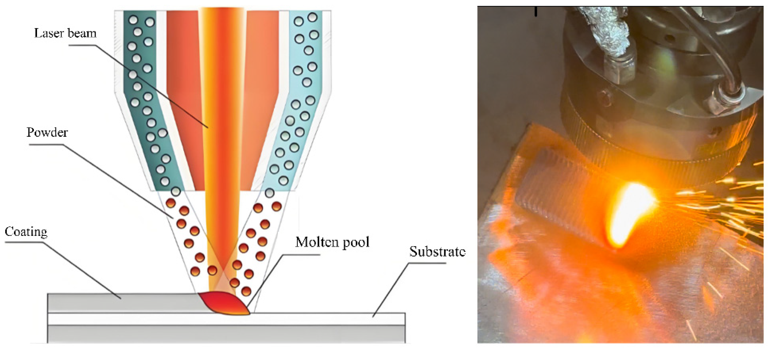
Prior to laser cladding, the surface of the 316 stainless steel substrate (200 mm × 200 mm × 15 mm) was ground and polished to remove the oxide layer and surface contaminants. The chemical composition of the substrate is presented in Table 1. The raw material powders consisted of Fe, Co, Cr, and Ni in equimolar proportions, with Nb added at a molar ratio of 0.5. All powders had a purity of 99.9%. The powder particle size ranged from 53 to 105 µm. The powders were uniformly mixed using ball milling under the following conditions: a ball-to-powder mass ratio of 10:1, a rotation speed of 100 rpm, and a milling duration of 5 h. The mixed powder was then dried in a vacuum drying oven at 90 °C for 3 h. The FeCoCrNiNb0.5 high-entropy alloy coating was deposited using a Trudiode 5000 fiber laser system equipped with a coaxial powder-feeding unit. The processing parameters included a laser power of 2500 W, a scanning speed of 750 mm·min−1, a powder feed rate of 22 g·min−1, a spot diameter of 2.5 mm, and an overlap ratio of 50%. Argon shielding gas was employed to prevent oxidation of the molten pool, with a flow rate of 20 L/min. A schematic diagram of the laser cladding process is shown in Figure 1.

2.2. Microstructure Characteristics

Metallographic specimens of FeCoCrNi and FeCoCrNiNb0.5 coatings were prepared using EDM wire-cutting technology. The specimen dimensions were 10 mm × 10 mm × 10 mm. Subsequently, specimens were ground and polished to achieve a scratch-free surface following the standard metallographic specimen preparation method. For corrosion resistance assessment, the metallographic specimens underwent corrosion with a VHCL/VHNO3 = 3:1 solution for 15 s. The phase composition of the coatings was analyzed using X-ray diffraction (XRD) with a detection angle ranging from 20 to 100°, a scanning speed of 4°/min, and voltages and currents set at 40 kV and 15 mA, respectively. The microstructure of the coatings was examined using field emission scanning electron microscopy (SEM, Zeiss, Germany) and energy dispersive spectroscopy (EDS, Oxford, UK). SEM and EDS were employed to investigate the microscopic morphology and elemental distribution of the coatings. Electron backscattering diffraction (EBSD) was utilized to detect the crystallographic features of the coatings, focusing on a representative cross-section of the coatings. Before EBSD characterization, the samples were electropolished using a 10% HClO4–alcohol solution with liquid nitrogen cooling. The electropolishing parameters were 20 V, −20 °C, and a step size of 0.5 μm.

2.3. Microhardness, Nano-Indentation and Wear Behavior

Nanoindentation measurements on the surfaces of FeCoCrNi and FeCoCrNiNb0.5 coatings were carried out using a nanoindenter. Prior to testing, the samples were ground and polished to minimize the influence of surface roughness. The testing parameters included a maximum load of 15 mN, a Poisson’s ratio of 0.3, and loading/unloading rates of 5 mN/min. For each sample, seven indents were performed, and the average value was reported. The cross-sectional microhardness was evaluated using a microhardness tester (Huayin, China,) under a load of 500 g with a dwell time of 5 s. Measurements were conducted from the top surface of the coating toward the substrate. At each depth, three indentations were performed to ensure reliability, and the mean value was calculated. To ensure testing accuracy, the average value was calculated after conducting the test seven times for each sample. For evaluating wear behavior, a reciprocating friction and wear testing machine was utilized. Reciprocating wear tests were conducted using a GCr15 steel ball (5 mm in diameter, Bruker, Germany) as the counterbody, with a sliding distance of 7 mm, a duration of 30 min, and a sliding speed of 700 mm/min. The worn surfaces were subsequently examined by SEM to elucidate the wear mechanisms.

3. Results and Discussion

3.1. Formed Phases of Two Coatings

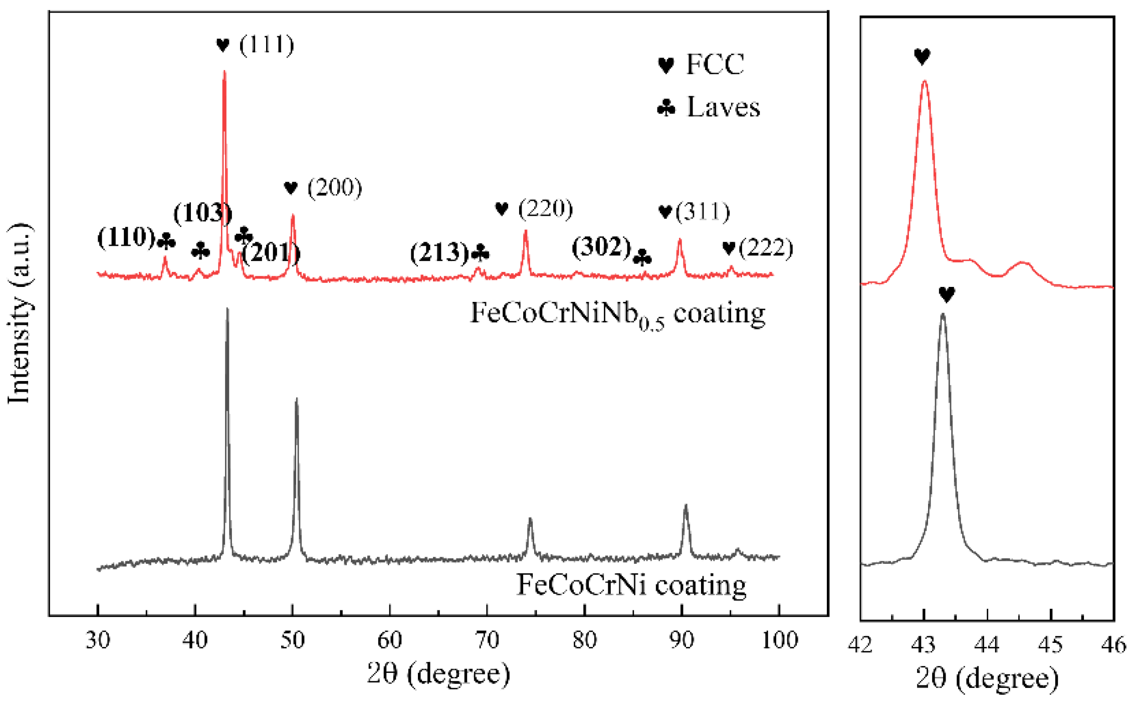
Figure 2 presents the XRD diffractograms comparing the FeCoCrNi coating with the FeCoCrNiNb0.5 HEA coating. In the case of the FeCoCrNi coating, the phase composition reveals a singular FCC phase structure. However, the FeCoCrNiNb0.5 HEA coating exhibits not only the FCC phase but also the presence of the Laves phase. Previous studies indicate that the introduction of Nb promotes the generation of the Laves phase, contributing significantly to the coating’s strength and hardness [18]. In Figure 2, the diffraction peaks of the FCC phase are evident in both HEA coatings within the range of 42–46°. The results demonstrate diffraction angles of 43.05° and 43.36° for the FeCoCrNi and FeCoCrNiNb0.5 coatings, respectively. These values are compared with the standard PDF (33-0397) of the FCC phase, which has a diffraction angle of 43.58°. The diffraction peaks of the FCC phase in both coatings are shifted to a lower angle, indicating a change in the lattice constants of the FCC phase. The lattice constant (a) of the FCC phase can be calculated using Bragg’s law of diffraction [19]:
d = a h 2 + k 2 + l 2
d h k l = λ 2 sin θ
Here, d represents the crystallographic spacing, h, k, l are the crystallographic indices, a is the lattice parameter, λ is the X-ray wavelength (1.5406 Å), and θ is the diffraction angle. According to the formula above, a shift in the diffraction angle toward lower angles corresponds to an increase in the lattice parameter, indicating enhanced lattice distortion within the FCC phase. The atomic radius of Nb (~146 pm) is substantially larger than those of Fe (117 pm), Cr (118 pm), Co (116 pm), and Ni (115 pm). Therefore, when Nb is dissolved into the FCC phase, it induces pronounced lattice distortion and generates a substantial coherent strain field. In addition, the high electronegativity and electron concentration of Nb disrupt the original chemical bonding network, leading to long-range electronic redistribution [20]. This combined effect is confirmed by XRD analysis, where the diffraction peaks of the Nb0.5 alloy shift toward lower angles, indicating lattice expansion. Such lattice distortion plays a key role in enhancing solid-solution strengthening and provides the driving force for the subsequent precipitation of the Laves phase. Moreover, the rapid thermal cycling associated with laser cladding further contributes to lattice distortion in the FCC phase, which accounts for the observed shift in FCC diffraction peaks toward lower angles in FeCoCrNi coatings.

3.2. Microstructure of Two HEA Coatings

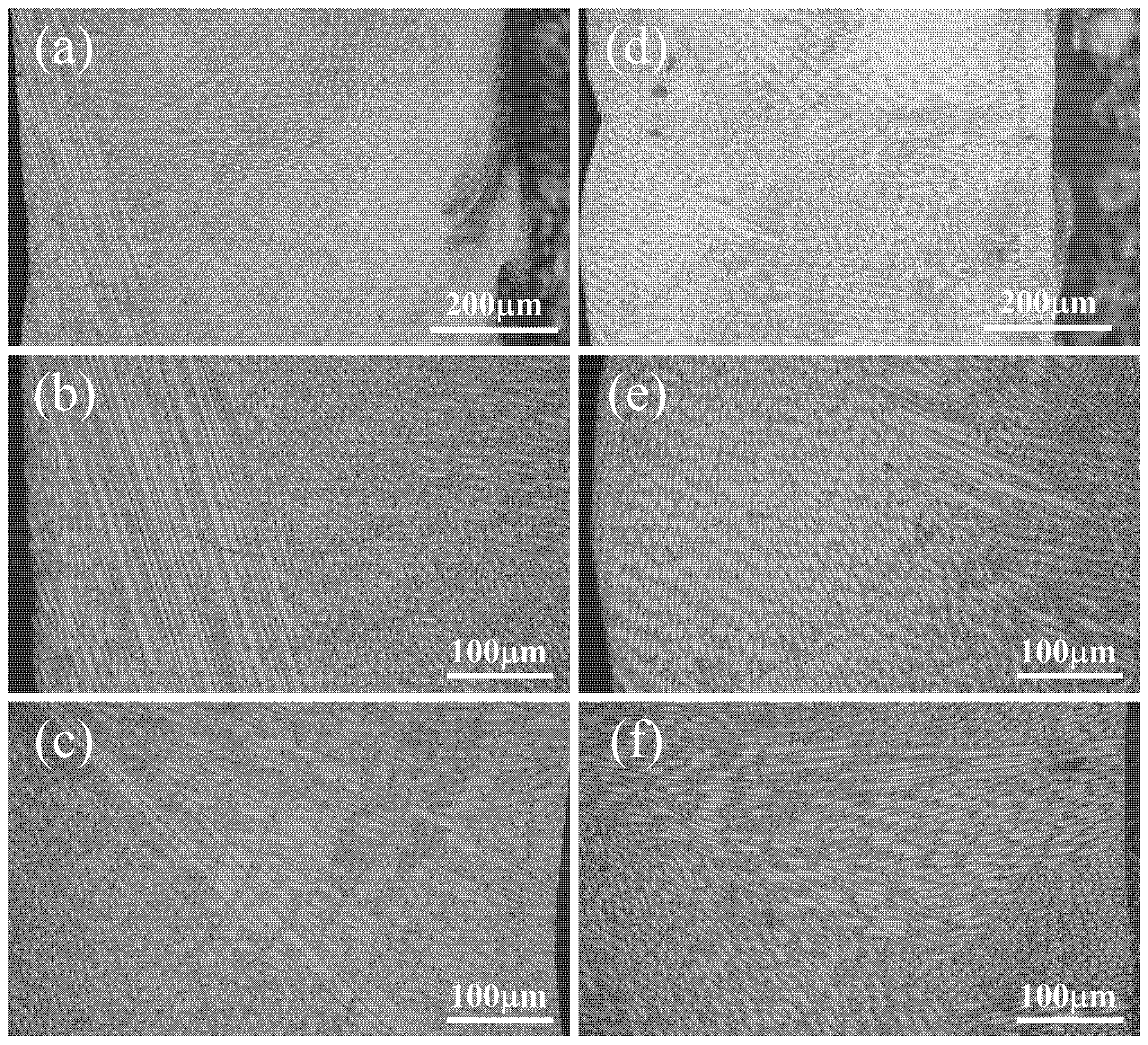
Figure 3 presents the microstructure and morphology of the FeCoCrNi and FeCoCrNiNb0.5 coatings. Both coatings exhibit a well-defined metallurgical bond with the substrate, with no obvious defects such as pores or cracks. Figure 3a–c show the microstructural evolution of the FeCoCrNi coating from the substrate to the top surface. The coating is primarily composed of dendritic structures. Near the coating–substrate interface, a thin layer of fine equiaxed grains is observed. This solidification behavior is consistent with non-equilibrium solidification theory [21]. The microstructural morphology is governed by the temperature gradient (G) and solidification rate (R), with the G/R ratio determining the growth mode. In the bonding region, the high temperature gradient and relatively low growth rate result in a large G/R value, leading to planar growth. As G decreases and R increases, the morphology transitions from planar to cellular and dendritic structures. When the G/R value becomes sufficiently low, equiaxed grains form within the coating [22]. Figure 3d–f show that the microstructure of the FeCoCrNiNb0.5 HEA coating is similar to that of the FeCoCrNi coating, consisting mainly of dendritic and equiaxed grains. A thin planar growth layer is also observed at the bonding interface. This consistent microstructural evolution further confirms the good metallurgical bonding and structural integrity of both coatings.
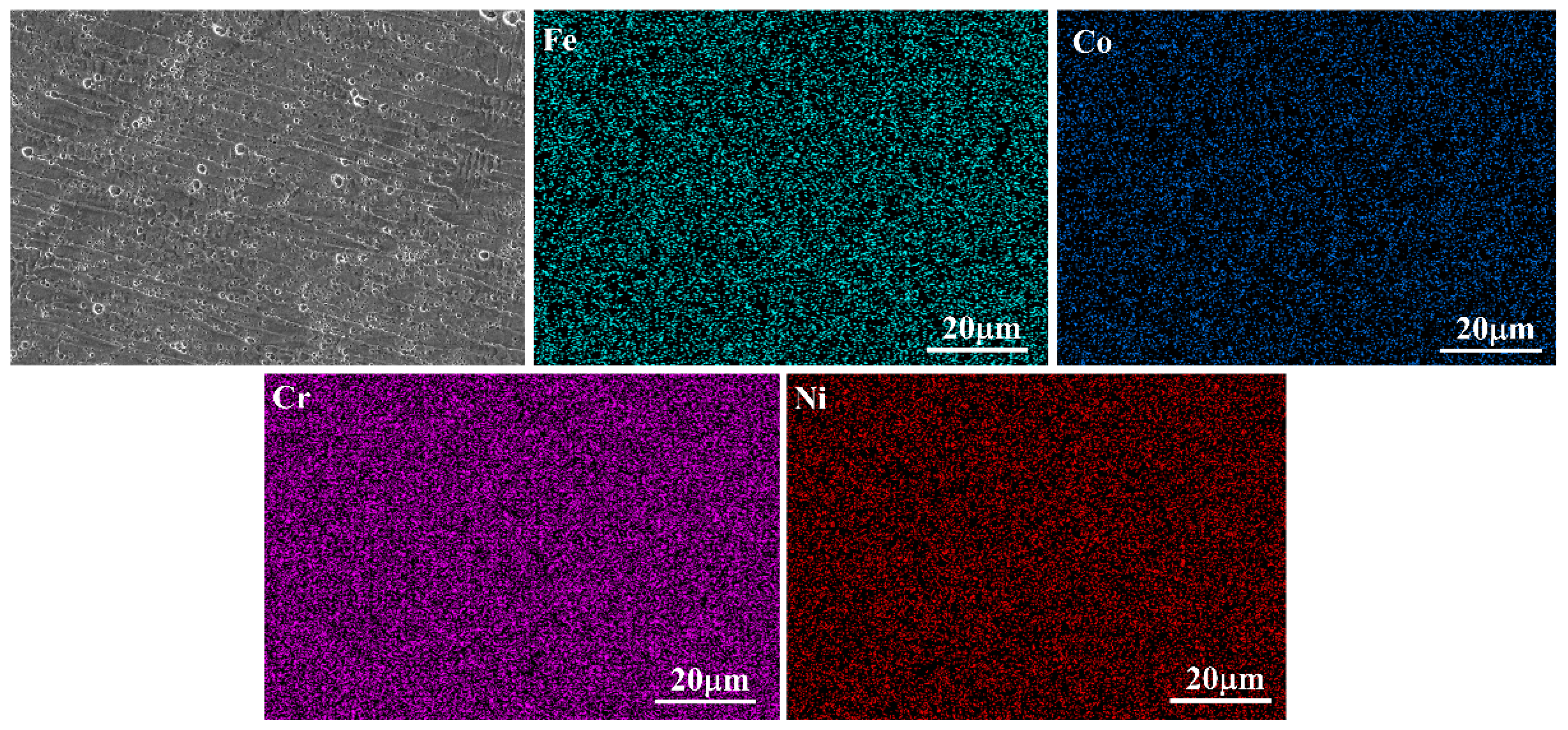
To further investigate the microstructure and elemental distribution of the FeCoCrNi and FeCoCrNiNb0.5 coatings, scanning electron microscopy (SEM) combined with energy-dispersive spectroscopy (EDS) was employed. Figure 4 presents the representative microstructure and corresponding elemental maps of the FeCoCrNi coating. The coating consists of dendrites and an interdendritic matrix, with a relatively uniform elemental distribution and no evident segregation, consistent with the metallographic observations.
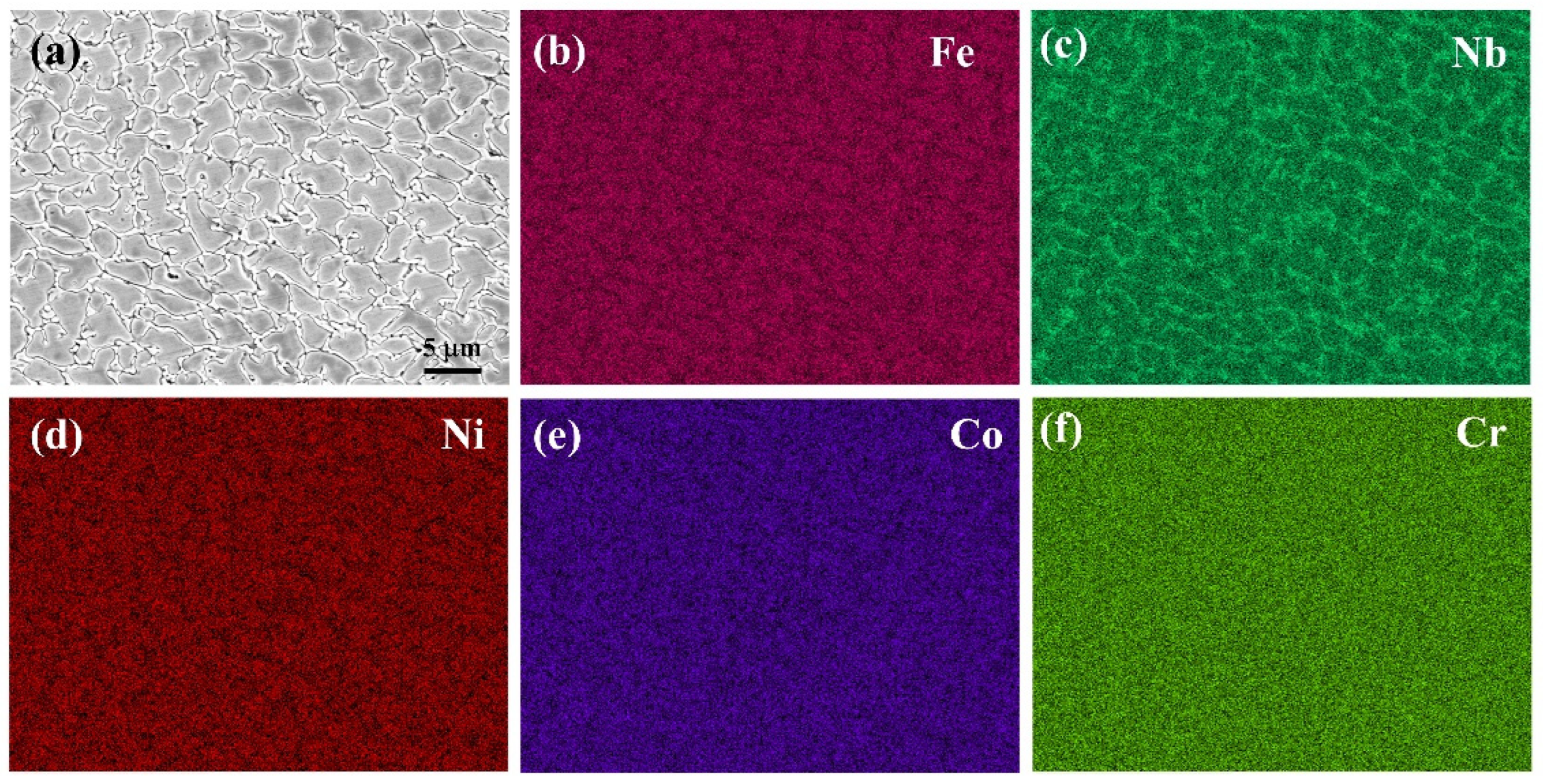
Figure 5 shows the typical microstructure of the FeCoCrNiNb0.5 coating, which is characterized by a cellular structure with fine second-phase particles distributed in the intercellular regions. EDS mapping reveals that Nb is depleted at the dendrite cores and preferentially segregates into the interdendritic regions. The pronounced Nb enrichment in these regions indicates that Nb segregation plays a key role in the formation of second-phase particles.

3.3. EBSD Analysis

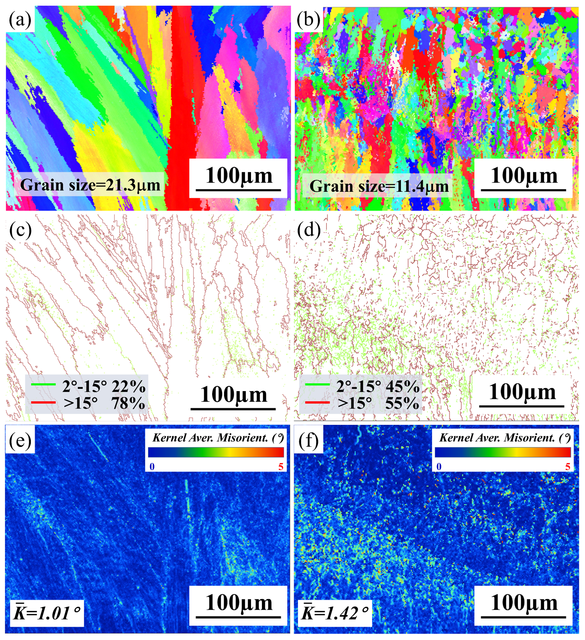
To further characterize the crystallographic features of the FeCoCrNi and FeCoCrNiNb0.5 coatings, electron backscatter diffraction (EBSD) was performed on representative regions. Figure 6a,b present the inverse pole figure (IPF) maps of the two coatings. The average grain sizes of the FeCoCrNi and FeCoCrNiNb0.5 coatings are 21.3 μm and 11.4 μm, respectively, indicating that Nb addition leads to significant grain refinement. Nb is preferentially segregated in the interdendritic regions, where Nb-rich intermetallic compounds are formed. These intermetallics promote heterogeneous nucleation, thereby refining the grain structure [23]. In addition, owing to the high melting point of Nb, its incorporation enhances compositional undercooling in the melt pool, further increasing the overall undercooling and contributing to grain refinement [24]. As a result, the FeCoCrNiNb0.5 coating exhibits a finer microstructure. Moreover, due to the Marangoni effect in the melt pool during laser cladding, convective flow leads to a certain degree of randomness in grain orientation in both coatings.
Figure 6c,d show the grain boundary distribution maps for the FeCoCrNi and FeCoCrNiNb0.5 coatings. In the FeCoCrNi coating, the fractions of high-angle grain boundaries (HAGBs) and low-angle grain boundaries (LAGBs) are 78% and 22%, respectively. In contrast, the FeCoCrNiNb0.5 coating exhibits 55% HAGBs and 45% LAGBs. The increased proportion of LAGBs indicates a higher internal dislocation density within the coating [25]. This is consistent with the kernel average misorientation (KAM) maps shown in Figure 6e,f. The average KAM values for the FeCoCrNi and FeCoCrNiNb0.5 coatings are 1.01° and 1.42°, respectively. With the KAM values, the geometrically necessary dislocation densities (ρGND) of the two coatings can be calculated using the following formula [26]:
ρ G N D = 2 K A M a v e μ b
Here, μ is the test step selected for EBSD testing (0.5 μm), and b is the Burgers vector (2.35 × 10⁻¹⁰). The calculated ρ G N D for the FeCoCrNi and FeCoCrNiNb0.5 coatings are 1.71 × 10¹⁵ m−2 and 2.42 × 10¹⁵ m−2, respectively. This indicates that the FeCoCrNiNb0.5 coating possesses a higher dislocation density, which is consistent with the observation from the grain-boundary distribution maps. A higher dislocation density can increase the energy required for crack propagation, thereby enhancing the toughness of the material [27]. Consequently, the FeCoCrNiNb0.5 coating exhibits improved strength.

3.4. Hardness Properties

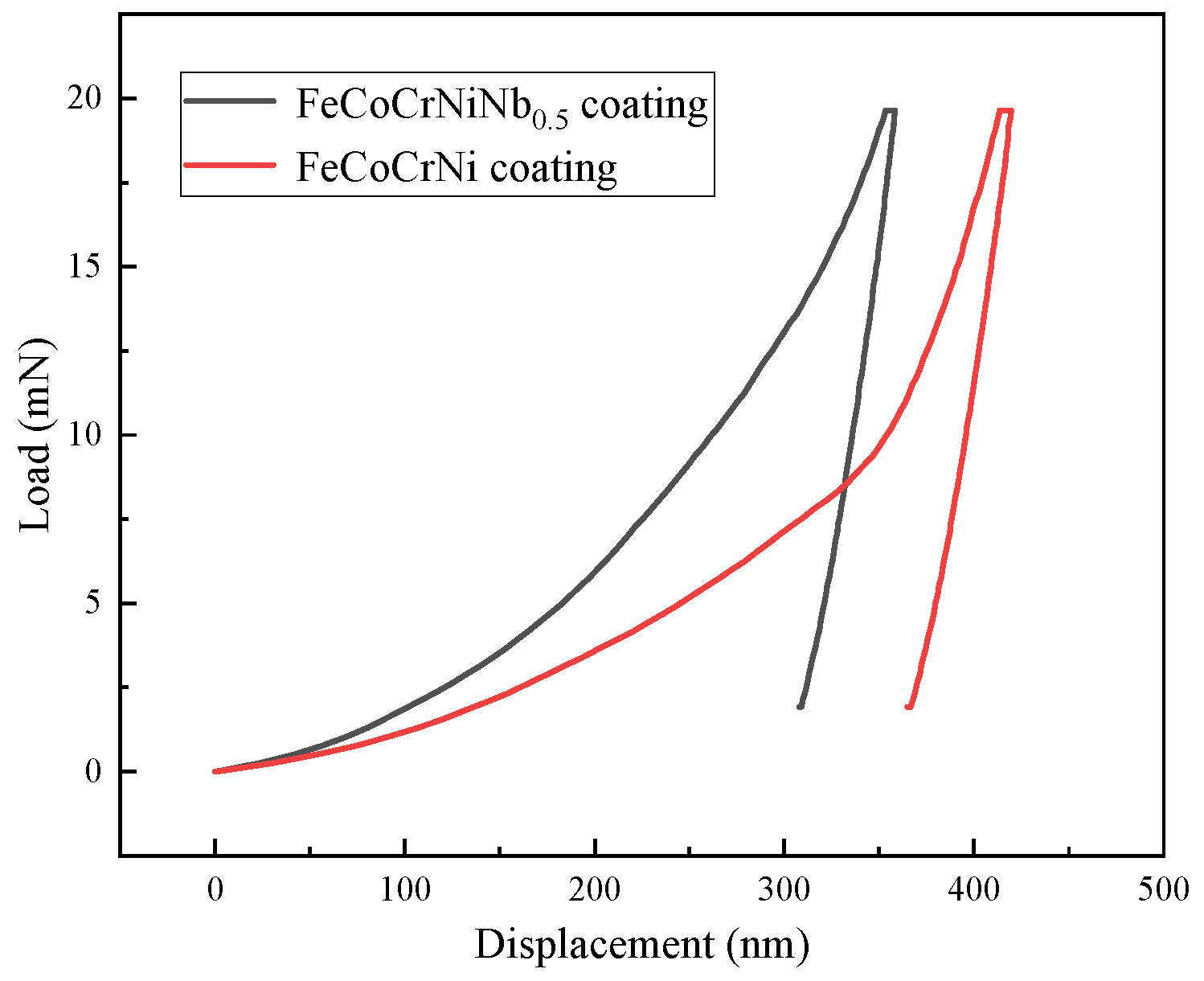
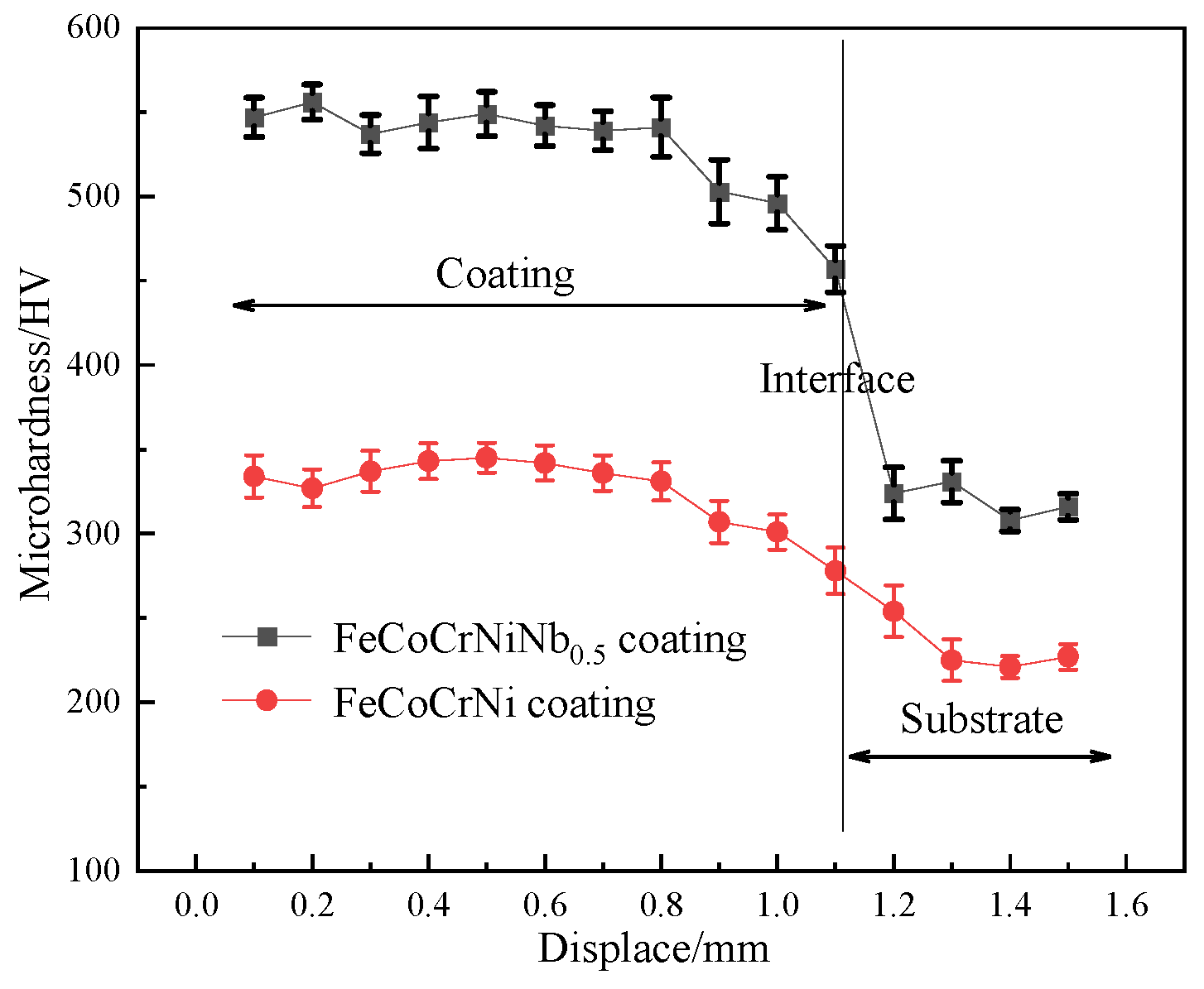
Figure 7 presents the load–displacement curves obtained from nanoindentation tests on the FeCoCrNi and FeCoCrNiNb0.5 coatings. The maximum indentation depth (dmax), nanohardness (H), and elastic modulus (E) were derived from these tests. Using these data, the ratios H/E and H3/E2 were calculated, as summarized in Table 1. The results show that under the same load, the dmax values for the FeCoCrNi and FeCoCrNiNb0.5 coatings are 354.62 nm and 279.45 nm, respectively, indicating that the Nb-containing coating possesses superior resistance to deformation. The nanohardness of the FeCoCrNi and FeCoCrNiNb0.5 coatings is 3.89 ± 0.17 GPa and 6.47 ± 0.23 GPa, respectively, demonstrating that the addition of Nb significantly enhances the nanohardness of the coating. Furthermore, the cross-sectional microhardness of both coatings was measured, as shown in Figure 8. The average microhardness of the FeCoCrNiNb0.5 coating is about 534 ± 12.7 HV, while that of the FeCoCrNi coating is about 327 ± 10.5 HV. Thus, the hardness of the FeCoCrNiNb0.5 coating is approximately 1.6 times that of the base alloy coating. Furthermore, the microhardness of the FeCoCrNiNb0.5 coating prepared in this work is significantly higher than that of the corresponding cast alloy [17] (Table 2).
The enhanced nanohardness of the FeCoCrNiNb0.5 high-entropy alloy coating is attributed to the synergistic effect of multiple strengthening mechanisms, including solid-solution strengthening, second-phase strengthening, grain-refinement strengthening, and dislocation strengthening. The analysis of these mechanisms is as follows. (1) Solid-solution strengthening: Combined XRD analysis and EDS mapping indicate that a portion of Nb atoms dissolves into the FCC phase, inducing severe lattice distortion. This distortion produces a solid-solution strengthening effect in the FCC matrix, thereby increasing its hardness [28]. (2) Second-phase strengthening: XRD results confirm the presence of a certain volume fraction of Laves phase uniformly distributed in the coating. As reported extensively, this Nb-rich Laves phase possesses high intrinsic hardness and acts as a second-phase strengthening constituent, significantly improving the overall coating hardness [29]. (3) Grain-refinement strengthening: According to EBSD results, the addition of Nb notably refines the coating’s grain size, increasing the density of grain boundaries. In line with the Hall–Petch relationship, a smaller grain size corresponds to a greater resistance to plastic deformation and thus higher hardness [30]. Therefore, the grain-refinement effect induced by Nb also contributes to the enhanced nanohardness. (4) Dislocation strengthening: The dislocation densities of the two coatings calculated via Equation (3) show that the FeCoCrNiNb0.5 coating possesses a higher dislocation density. During plastic deformation, dislocation intersections impede further slip, raising the stress required for deformation and thereby increasing the material’s strength and hardness [31,32]. In summary, the improved hardness of the FeCoCrNiNb0.5 high-entropy alloy coating results from the combined action of solid-solution strengthening by Nb atoms, second-phase strengthening by the Nb-rich Laves phase, grain-refinement strengthening due to Nb addition, and dislocation strengthening.
Additionally, the elastic modulus of the material also influences wear resistance. The H/E ratio represents the maximum load-carrying capacity of the material within its elastic limit, and wear resistance is directly proportional to the H/E value [33]. The H3/E2 value indicates the coating’s resistance to plastic deformation [34]. The H/E values for FeCoCrNiNb0.5 HEA coating and FeCoCrNi coating are 0.026 and 0.017, respectively, and the H3/E2 values are 0.0044 and 0.0012, respectively. These results indicate that FeCoCrNiNb0.5 HEA coatings possess superior wear resistance and resistance to plastic deformation.

3.5. Wear Behavior

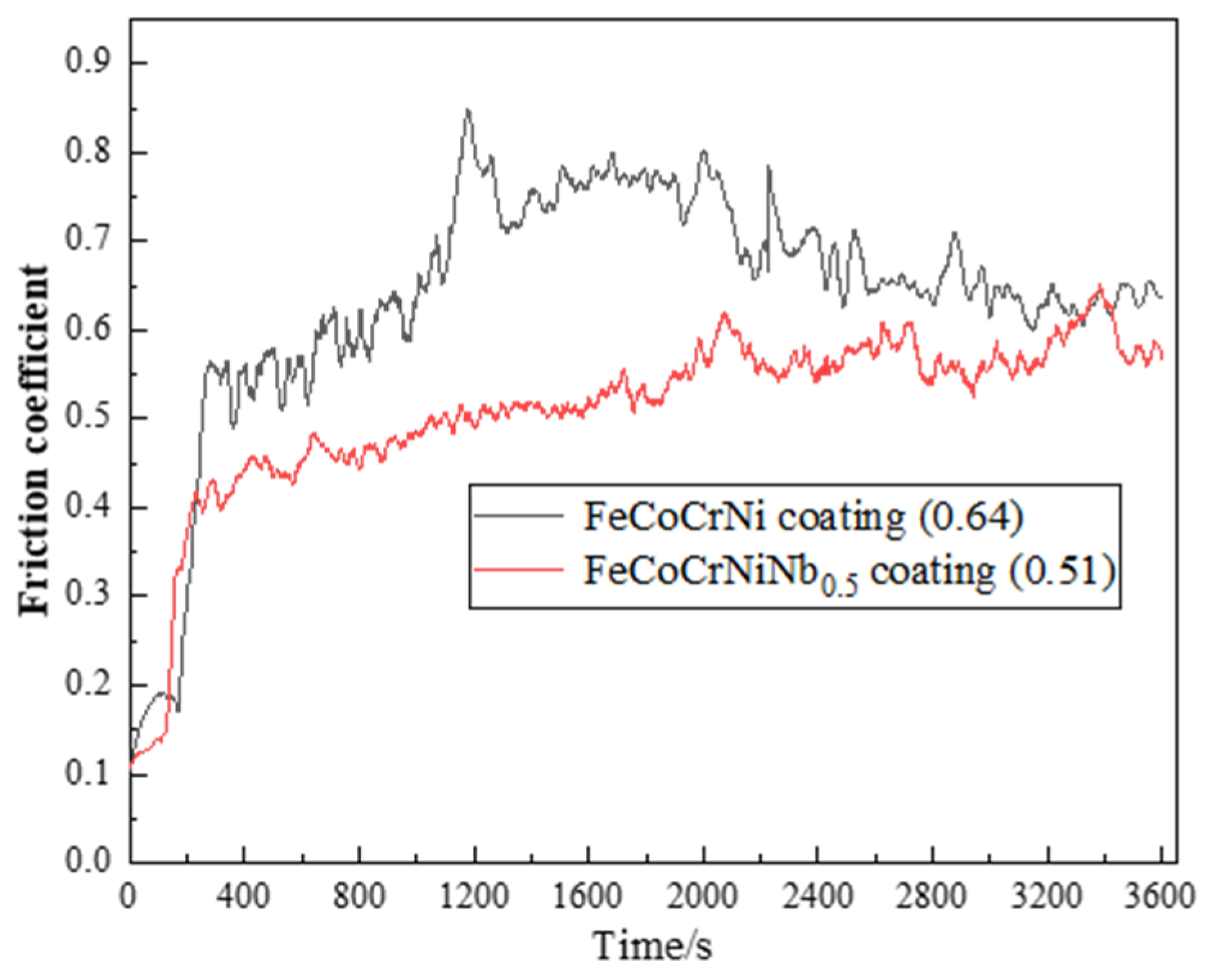
Figure 9 illustrates the dry sliding friction coefficient versus time curves for the FeCoCrNi coating and the FeCoCrNiNb0.5 HEA coating. The average dry sliding friction coefficients for the FeCoCrNi coating and the FeCoCrNiNb0.5 HEA coating are 0.69 and 0.52, respectively. Observations from the figure indicate that both coatings exhibit sharp fluctuations in the friction coefficient during the early stages of wear. This phenomenon is attributed to the severe plastic deformation of the coatings at the onset of wear, leading to increased surface roughness and resulting in sharp fluctuations in the friction coefficient [35,36]. As wear behavior progresses beyond 200 s, the friction coefficient tends to stabilize. However, the friction coefficient fluctuation of the FeCoCrNi coating is more pronounced. This is attributed to the lower hardness of the coating, where the frictional contact of the wear surface repeatedly chips, leading to coating peeling and causing fluctuations in the friction coefficient. In contrast, the Laves phase generated in the FeCoCrNiNb0.5 HEA coating has high hardness, acting as a support in the wear process. This prevents wear and spalling of the soft matrix FCC phase, avoiding more severe plastic deformation of the coating and reducing the coefficient of friction.
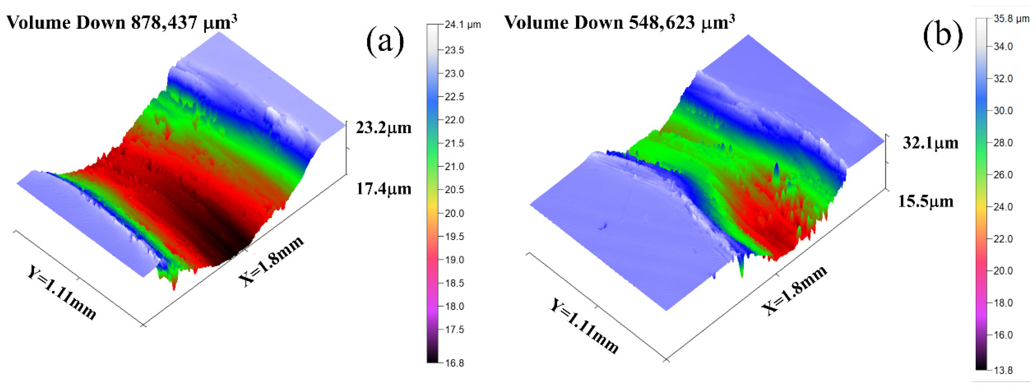
Figure 10 displays representative three-dimensional wear morphologies of the two high-entropy alloy coatings. The wear volume of the FeCoCrNi coating is 8.78 × 105 μm3, while that of the FeCoCrNiNb0.5 coating is 5.49 × 105 μm3. Evidently, the addition of Nb significantly reduces the wear volume and enhances the wear resistance of the coating. This observation aligns with the nanoindentation results for hardness, H/E, and H3/E2. The improved wear performance is attributed to the combined effects of solid-solution strengthening from Nb and the formation of a Laves phase. During wear, the hard Laves phase acts as a load-bearing constituent, mitigating direct wear of the FCC matrix. Furthermore, solid-solution strengthening by Nb also increases the hardness and wear resistance of the FCC phase itself [37].
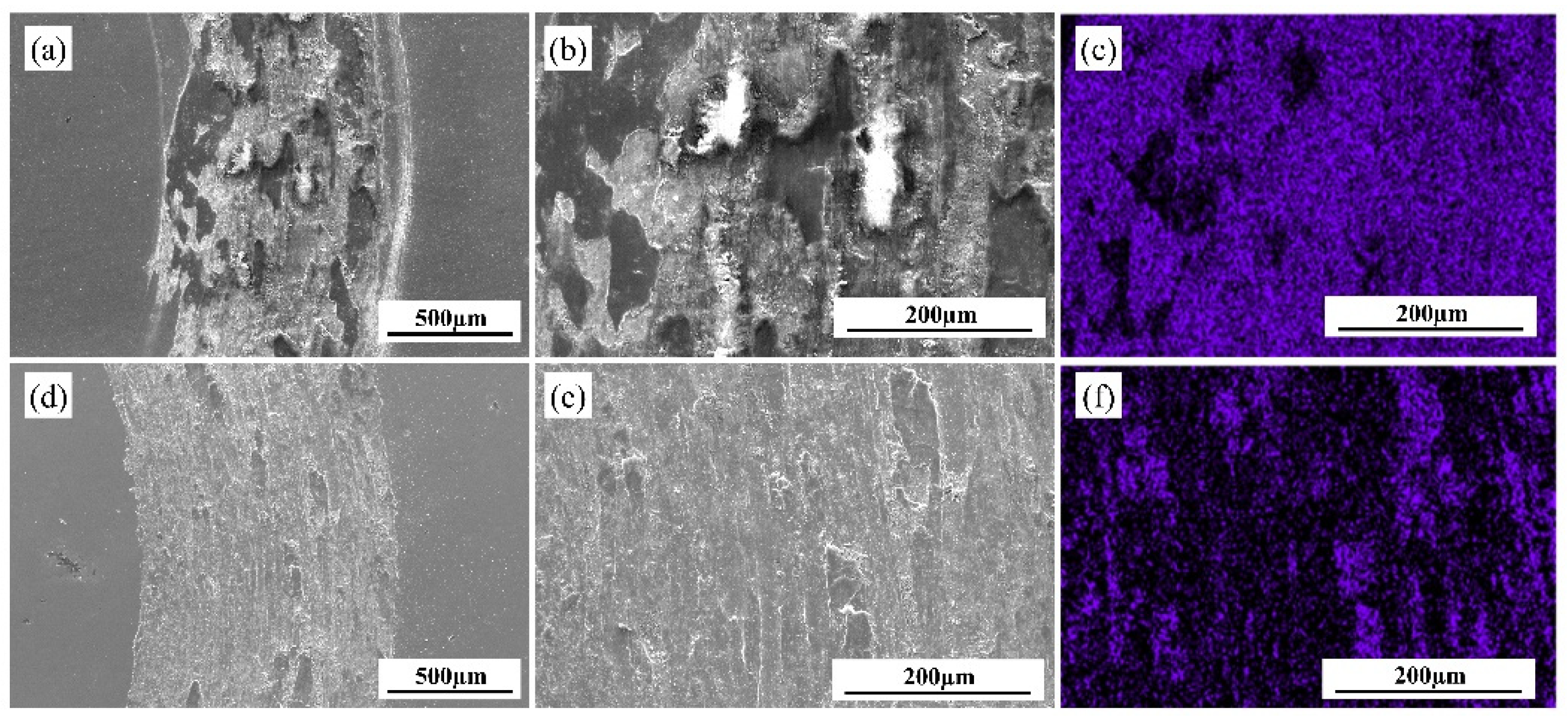
To further investigate the dry-sliding wear mechanisms of the two coatings, the worn surfaces were examined by scanning electron microscopy (SEM). Figure 11a–c show the wear morphology of the FeCoCrNi coating. Scattered debris, delamination pits, and adhesive zones are visible, along with severe plastic deformation and distinct grooves on the wear scar. During sliding, repeated contact between the counterpart and the coating induced cold welding, leading to material removal and thus adhesive wear. The detached debris then participated in three-body abrasion, repeatedly ploughing the wear surface and forming grooves, which corresponds to abrasive wear [38]. Moreover, the high applied load caused severe plastic deformation, and the combined effect of cyclic loading and wear exceeded the coating’s endurance limit, resulting in surface cracking and surface fatigue wear [39]. Therefore, the wear mechanisms of the FeCoCrNi coating are identified as adhesive wear, surface fatigue wear, and abrasive wear.
Figure 11d–f presents the wear morphology of the FeCoCrNiNb0.5 coating. Grooves and adhesive zones are observed, indicating that abrasive wear and adhesive wear are active mechanisms. However, compared with the FeCoCrNi coating, the addition of Nb significantly reduces both the extent of adhesion and the depth of the grooves. This is attributed to the presence of hard Nb-rich Laves phase precipitated in the interdendritic regions, which lowers the susceptibility of the FCC matrix to scratching and delamination. In addition, solid-solution strengthening by Nb enhances the strength and deformation resistance of the FCC phase, further reducing the tendency for material removal [40].
Furthermore, energy-dispersive X-ray spectroscopy (EDS) was performed on the worn surfaces to evaluate oxidative wear. Oxygen was detected on both coatings, confirming that oxidative wear occurred during sliding. However, the oxygen content on the FeCoCrNiNb0.5 coating was markedly lower than that on the FeCoCrNi coating, indicating a less pronounced oxidative wear effect. In other words, oxidative wear was more severe in the FeCoCrNi coating.
In summary, the wear mechanisms of the FeCoCrNi coating comprise adhesive wear, surface fatigue wear, abrasive wear, and oxidative wear, whereas those of the FeCoCrNiNb0.5 coating are adhesive wear, abrasive wear, and a milder degree of oxidative wear. Based on the average friction coefficient, wear volume, and wear morphology, it is evident that the addition of Nb significantly improves the wear resistance of the FeCoCrNi coating.

4. Conclusions

In this study, FeCoCrNi and FeCoCrNiNb0.5 high-entropy alloy coatings were successfully fabricated by laser cladding, and the role of Nb under rapid non-equilibrium solidification conditions was systematically clarified. The main conclusions are summarized as follows:
(1)
Nb addition significantly alters the phase constitution and microstructural evolution. While the FeCoCrNi coating consists of a single FCC phase, the FeCoCrNiNb0.5 coating exhibits a dual-phase structure composed of FCC and Nb-rich Laves phase. The formation of the Laves phase is closely associated with Nb segregation in interdendritic regions under non-equilibrium solidification, highlighting the strong coupling between composition redistribution and phase selection during laser cladding.
(2)
The introduction of Nb leads to pronounced grain refinement and increased lattice distortion, which are reflected by reduced grain size and elevated KAM and dislocation density. This behavior originates from the combined effects of heterogeneous nucleation induced by Nb-rich intermetallics and enhanced compositional undercooling caused by the high melting point of Nb.
(3)
As a result of the synergistic strengthening mechanisms—including grain refinement, solid-solution strengthening, dislocation strengthening, and Laves phase strengthening—the FeCoCrNiNb0.5 coating exhibits significantly improved mechanical performance, as evidenced by higher hardness and enhanced resistance to plastic deformation (higher H/E and H3/E2 values). Notably, the strengthening effect achieved under laser cladding conditions is more pronounced than that reported for cast alloys, emphasizing the advantage of non-equilibrium processing.
(4)
The FeCoCrNiNb0.5 coating demonstrates superior tribological performance, with a reduced friction coefficient (0.52 vs. 0.69) and lower wear volume. The improved wear resistance is attributed to the enhanced load-bearing capacity and deformation resistance provided by the Laves phase, which suppresses severe plastic deformation and mitigates material removal during sliding.

Author Contributions

Investigation, C.Q., T.W. and Z.L.; Data curation, T.W. and Z.L.; Writing—review & editing, C.Q.; Funding acquisition, T.W. All authors have read and agreed to the published version of the manuscript.

Funding

This research was funded by National Natural Science Foundation of China (grant number 52177047).

Institutional Review Board Statement

Not applicable.

Informed Consent Statement

Not applicable.

Data Availability Statement

The original contributions presented in this study are included in the article. Further inquiries can be directed to the corresponding author.

Conflicts of Interest

The authors declare no conflict of interest.

References

  1. Gu, X.; Tian, H.; Wang, J.; Liang, T.; Wei, T.; Niu, X.; Cai, G. Operational instability of a high-rotational-speed electric pump in a hybrid rocket motor. Aerosp. Sci. Technol. 2023, 140, 108496. [Google Scholar] [CrossRef]
  2. Gao, Q.; Wang, X.; Zhang, Y. Multi–physical-field characteristics modeling and structure optimization for kW-level ultra-high-speed PM motors with integrated support system. Chin. J. Aeronaut. 2023, 36, 455–467. [Google Scholar] [CrossRef]
  3. Liu, X.; Xu, D.; Lin, J.; Zhang, L.; Zeng, Y.; Chen, Q. Failure analysis and factors influencing spline wear in hydraulic motors of charging pumps in nuclear power plants. Eng. Fail. Anal. 2024, 156, 107780. [Google Scholar] [CrossRef]
  4. Sang, H.; Zeng, J.; Qi, Y.; Mu, J.; Gan, F. Study on wheel wear mechanism of high-speed train in accelerating conditions. Wear 2023, 516–517, 204597. [Google Scholar] [CrossRef]
  5. Wang, Z.; Wang, R.; Crosbee, D.; Allen, P.; Ye, Y.; Zhang, W. Wheel wear analysis of motor and unpowered car of a high-speed train. Wear 2020, 444–445, 203136. [Google Scholar] [CrossRef]
  6. Xu, T.Z.; Zhang, S.; Wang, Z.Y.; Zhang, C.H.; Zhang, D.X.; Wang, M.; Wu, C.L. Wear behavior of graphite self-lubricating Babbitt alloy composite coating on 20 steel prepared by laser cladding. Eng. Fail. Anal. 2022, 141, 106698. [Google Scholar] [CrossRef]
  7. Qunshuang, M.; Yajiang, L.; Juan, W.; Kun, L. Microstructure evolution and growth control of ceramic particles in wide-band laser clad Ni60/WC composite coatings. Mater. Des. 2016, 92, 897–905. [Google Scholar] [CrossRef]
  8. Liu, Q.-S.; Liu, X.-B.; Wang, G.; Liu, Y.-F.; Meng, Y.; Zhang, S.-H. Effect of Cu content on microstructure evolution and tribological behaviors of Ni60 composite coatings on 45# steel by laser cladding. Opt. Laser Technol. 2022, 156, 108549. [Google Scholar] [CrossRef]
  9. Cai, Y.; Zhu, L.; Cui, Y.; Han, J. Manufacturing of FeCoCrNi + FeCoCrNiAl laminated high-entropy alloy by laser melting deposition (LMD). Mater. Lett. 2021, 289, 129445. [Google Scholar] [CrossRef]
  10. Jadhav, M.S.; Sahane, D.; Verma, A.; Singh, S. Thermal stability and thermal expansion behavior of FeCoCrNi2Al high entropy alloy. Adv. Powder Technol. 2021, 32, 378–384. [Google Scholar] [CrossRef]
  11. Leila Panahi, S.; Garcia-Ramón, M.; Pineda, E.; Bruna, P. New (FeCoCrNi)-(B,Si) high-entropy metallic glasses, study of the crystallization processes by X-ray diffraction and Mössbauer spectroscopy. J. Non-Cryst. Solids 2020, 547, 120301. [Google Scholar] [CrossRef]
  12. Zhou, R.; Chen, G.; Liu, B.; Wang, J.; Han, L.; Liu, Y. Microstructures and wear behaviour of (FeCoCrNi)1-x(WC)x high entropy alloy composites. Int. J. Refract. Met. Hard Mater. 2018, 75, 56–62. [Google Scholar] [CrossRef]
  13. Dai, C.; Zhao, T.; Du, C.; Liu, Z.; Zhang, D. Effect of molybdenum content on the microstructure and corrosion behavior of FeCoCrNiMox high-entropy alloys. J. Mater. Sci. Technol. 2020, 46, 64–73. [Google Scholar] [CrossRef]
  14. Peng, Y.B.; Zhang, W.; Mei, X.L.; Wang, H.J.; Zhang, M.Y.; Wang, L.; Li, X.F.; Hu, Y. Microstructures and mechanical properties of FeCoCrNi-Mo High entropy alloys prepared by spark plasma sintering and vacuum hot-pressed sintering. Mater. Today Commun. 2020, 24, 101009. [Google Scholar] [CrossRef]
  15. Li, L.Y.; Sun, C.H.; Ruan, Y.; Wei, B. Duplex corrosion mechanisms correlated to α/γ phase selection in containerlessly processed Fe-Cr-Ni-Mo alloy. Corros. Sci. 2023, 221, 111311. [Google Scholar] [CrossRef]
  16. He, F.; Wang, Z.; Cheng, P.; Wang, Q.; Li, J.; Dang, Y.; Wang, J.; Liu, C.T. Designing eutectic high entropy alloys of CoCrFeNiNbx. J. Alloys Compd. 2016, 656, 284–289. [Google Scholar] [CrossRef]
  17. Yu, Y.; He, F.; Qiao, Z.; Wang, Z.; Liu, W.; Yang, J. Effects of temperature and microstructure on the triblogical properties of CoCrFeNiNbx eutectic high entropy alloys. J. Alloys Compd. 2016, 775, 1376–1385. [Google Scholar] [CrossRef]
  18. Liang, H.; Miao, J.; Gao, B.; Deng, D.; Wang, T.; Lu, Y.; Cao, Z.; Jiang, H.; Li, T.; Kang, H. Microstructure and tribological properties of AlCrFe2Ni2W0.2Mo0.75 high-entropy alloy coating prepared by laser cladding in seawater, NaCl solution and deionized water. Surf. Coat. Technol. 2020, 400, 126214. [Google Scholar] [CrossRef]
  19. Yang, H.; Meng, L.; Luo, S.; Wang, Z. Microstructural evolution and mechanical performances of selective laser melting Inconel 718 from low to high laser power. J. Alloys Compd. 2020, 828, 154473. [Google Scholar] [CrossRef]
  20. Xu, T.Z.; Zhang, S.; Wang, L.; Du, Y.; Wu, C.L.; Zhang, C.H.; Sun, X.Y.; Chen, H.T.; Chen, J. Influence of scanning speed on the microstructure, nanoindentation characteristics and tribological behavior of novel maraging steel coatings by laser cladding. Mater. Charact. 2023, 205, 113335. [Google Scholar] [CrossRef]
  21. Cen, L.; Du, W.; Gong, M.; Lu, Y.; Zhang, C.; Gao, M. Effect of high-frequency beam oscillation on microstructures and cracks in laser cladding of Al-Cu-Mg alloys. Surf. Coat. Technol. 2022, 447, 128852. [Google Scholar] [CrossRef]
  22. Shi, L.; Jiang, L.; Gao, M. Numerical research on melt pool dynamics of oscillating laser-arc hybrid welding. Int. J. Heat Mass Transf. 2022, 185, 122421. [Google Scholar] [CrossRef]
  23. Li, Z.; Taheri, M.; Torkamany, P.; Heidarpour, I.; Torkamany, M.J. Laser cladding of NiCrCoFeNbMoX high-entropy alloy to increase resistance to corrosion of gas turbine blades. Vacuum 2024, 219, 112749. [Google Scholar] [CrossRef]
  24. Zhu, C.; Xu, L.; Liu, M.; Guo, M.; Wei, S. A review on improving mechanical properties of high entropy alloy: Interstitial atom doping. J. Mater. Res. Technol. 2023, 24, 7832–7851. [Google Scholar] [CrossRef]
  25. Jiang, D.; Cui, H.; Chen, H.; Zhao, X.; Ma, G.; Song, X. Wear and corrosion properties of B4C-added CoCrNiMo high-entropy alloy coatings with in-situ coherent ceramic. Mater. Des. 2021, 210, 110068. [Google Scholar] [CrossRef]
  26. Xu, W.; Chen, M.; Lu, X.; Zhang, D.-W.; Singh, H.-P.; Yu, J.-S.; Pan, Y.; Qu, X.-H.; Liu, C.-Z. Effects of Mo content on corrosion and tribocorrosion behaviours of Ti-Mo orthopaedic alloys fabricated by powder metallurgy. Corros. Sci. 2020, 168, 108557. [Google Scholar] [CrossRef]
  27. Juan, Y.F.; Li, J.; Jiang, Y.Q.; Jia, W.L.; Lu, Z.J. Modified criterions for phase prediction in the multi-component laser-clad coatings and investigations into microstructural evolution/wear resistance of FeCrCoNiAlMox laser-clad coatings. Appl. Surf. Sci. 2019, 465, 700–714. [Google Scholar] [CrossRef]
  28. Guo, Y.; Liu, L.; Zhang, Y.; Qi, J.; Wang, B.; Zhao, Z.; Shang, J.; Xiang, J. A superfine eutectic microstructure and the mechanical properties of CoCrFeNiMox high-entropy alloys. J. Mater. Res. 2018, 33, 3258–3265. [Google Scholar] [CrossRef]
  29. Chen, X.-G.; Qin, G.; Gao, X.-F.; Chen, R.-R.; Song, Q.; Cui, H.-Z. Strengthening CoCrFeNi high-entropy alloy by Laves and boride phases. China Foundry 2022, 19, 457–463. [Google Scholar] [CrossRef]
  30. Shu, F.; Zhang, B.; Liu, T.; Sui, S.; Liu, Y.; He, P.; Liu, B.; Xu, B. Effects of laser power on microstructure and properties of laser cladded CoCrBFeNiSi high-entropy alloy amorphous coatings. Surf. Coat. Technol. 2019, 358, 667–675. [Google Scholar] [CrossRef]
  31. Wang, J.; Zou, J.; Yang, H.; Liu, Z.; Ji, S. High strength and ductility of an additively manufactured CrCoNi medium-entropy alloy achieved by minor Mo doping. Mater. Sci. Eng. A 2022, 843, 143129. [Google Scholar] [CrossRef]
  32. Wang, W.; Wang, J.; Sun, Z.; Li, J.; Li, L.; Song, X.; Wen, X.; Xie, L.; Yang, X. Effect of Mo and aging temperature on corrosion behavior of (CoCrFeNi)100-xMox high-entropy alloys. J. Alloys Compd. 2020, 812, 152139. [Google Scholar] [CrossRef]
  33. Dai, C.; Luo, H.; Li, J.; Du, C.; Liu, Z.; Yao, J. X-ray photoelectron spectroscopy and electrochemical investigation of the passive behavior of high-entropy FeCoCrNiMox alloys in sulfuric acid. Appl. Surf. Sci. 2020, 499, 143903. [Google Scholar]
  34. Brownlie, F.; Hodgkiess, T.; Pearson, A.; Galloway, A.M. A study on the erosion-corrosion behaviour of engineering materials used in the geothermal industry. Wear 2021, 477, 203821. [Google Scholar] [CrossRef]
  35. Duan, C.; Kostka, A.; Li, X.; Peng, Z.; Kutlesa, P.; Pippan, R.; Werner, E. Deformation-induced homogenization of the multi-phase senary high-entropy alloy MoNbTaTiVZr processed by high-pressure torsion. Mater. Sci. Eng. A 2023, 871, 144923. [Google Scholar] [CrossRef]
  36. Gong, N.; Karyappa, R.; Meng, T.L.; Wang, Y.; Teo, S.L.; Cao, J.; Lin, M.; Huang, X.; Tan, C.K.I.; Suwardi, A.; et al. Synthesis and structural characterizations of CrCoFeNiMnx (0 ≤ x ≤ 1) high-entropy-alloy thin films by thermal reduction in hydrogen. J. Mater. Sci. 2023, 58, 12058–12069. [Google Scholar] [CrossRef]
  37. Wei, S.-Y.; Wang, C.-M.; Peng, W.-Y.; Luo, R.-K.; Chen, Y.; Wan, Z.-Z.; Jin, Y. Effects of process parameters and annealing on microstructure and properties of CoCrFeMnNi high-entropy alloy coating prepared by plasma cladding. China Foundry 2023, 20, 491–502. [Google Scholar] [CrossRef]
  38. Liu, T.-Y.; Lou, Y.-C.; Zhang, S.; Zhu, Z.-H.; Zhao, J.; Liu, S.-B.; Shi, K.; Zhao, N. A novel Ti-5.55Al-6.70Zr-1.50V-0.70Mo-3.41Nb-0.21Si alloy designed using cluster-plus-glue-atom model for laser additive manufacturing. China Foundry 2023, 20, 414–422. [Google Scholar] [CrossRef]
  39. Wei, Y.-P.; Yang, H.; Cheng, J.-C.; Gao, P.; Shi, J.; Lin, F.; Yu, B. Compression behavior of 316L lattice structures produced by indirect additive manufacturing. China Foundry 2023, 20, 83–88. [Google Scholar] [CrossRef]
  40. Brownlie, F.; Hodgkiess, T.; Fanicchia, F. Erosion-corrosion behaviour of CoCrFeNiMo0.85 and Al0.5CoCrFeNi complex concentrated alloys produced by laser metal deposition. Surf. Coat. Technol. 2021, 423, 127634. [Google Scholar] [CrossRef]
Figure 1. Schematic diagram of laser cladding.
Coatings 16 00595 g001
Figure 2. XRD patterns of the FeCoCrNi coating and FeCoCrNiNb0.5 HEA coating.
Coatings 16 00595 g002
Figure 3. Metallographic micromorphology of FeCoCrNi coating and FeCoCrNiNb0.5 HEA coating. (ac) FeCoCrNi coating; (df) FeCoCrNiNb0.5 HEA coating.
Coatings 16 00595 g003
Figure 4. SEM morphology and EDS element distribution of FeCoCrNi coating.
Coatings 16 00595 g004
Figure 5. SEM morphology and EDS element distribution of FeCoCrNiNb0.5 HEA coating. (a): SEM morphology; (bf): EDS element distribution.
Coatings 16 00595 g005
Figure 6. IPF map of the two coatings: (a,c,e) FeCoCrNi coating; (b,d,f) FeCoCrNiNb0.5 HEA coating.
Coatings 16 00595 g006
Figure 7. Load–displacement curves of two HEA coatings.
Coatings 16 00595 g007
Figure 8. The cross-sectional microhardness of the two coatings.
Coatings 16 00595 g008
Figure 9. Friction coefficient profiles of two HEA coatings under dry sliding wear conditions.
Coatings 16 00595 g009
Figure 10. 3D wear morphology of two coatings: (a) FeCoCrNi coating; (b) FeCoCrNiNb0.5 HEA coating.
Coatings 16 00595 g010
Figure 11. Dry sliding wear morphology of two coatings: (ac) FeCoCrNi coating; (df) FeCoCrNiNb0.5 HEA coating.
Coatings 16 00595 g011
Table 1. Chemical composition of 316 steel (Wt.%).
ElementCrNiMoFeMnC
Wt.%16.3012.122.21Bal.0.110.08
Table 2. Nanoindentation-derived parameters for the two coatings.
SampleH (GPa)E (GPa)dmax (nm)H/EH3/E2
FeCoCrNiNb0.57.81 ± 0.13244.61256.580.0320.0079
FeCoCrNi4.33 ± 0.16222.20340.740.0200.0016
Disclaimer/Publisher’s Note: The statements, opinions and data contained in all publications are solely those of the individual author(s) and contributor(s) and not of MDPI and/or the editor(s). MDPI and/or the editor(s) disclaim responsibility for any injury to people or property resulting from any ideas, methods, instructions or products referred to in the content.