Article

Load and Velocity Dependence of Friction at Iron–Silica Interfaces: An Atomic-Scale Study

by
Xiang Jiao
1,
Guochen Huang
2,
Ouwen Chen
2,
Qian Cheng
2,
Chenchen Peng
1 and
Guoqing Wang
2,*
1
School of Automobile and Traffic Engineering, Wuxi University of Technology, Wuxi 214121, China
2
College of Mechanical and Electronic Engineering, Nanjing Forestry University, Nanjing 210037, China
*
Author to whom correspondence should be addressed.
Coatings 2025, 15(11), 1252; https://doi.org/10.3390/coatings15111252
Submission received: 22 September 2025 / Revised: 21 October 2025 / Accepted: 25 October 2025 / Published: 29 October 2025

Abstract

Understanding the microscopic interaction between agricultural tillage tools and soil is essential for improving wear resistance. In this study, molecular dynamics (MD) simulations are employed to investigate the tribological behavior of the Fe–SiO2 interface under varying loads and sliding velocities. The results demonstrate that the coefficient of friction increases with both normal load and sliding velocity, accompanied by a clear running-in stage. Under high loads, significant plastic deformation occurs, characterized by asymmetric atomic pile-up, expansion of the strain field, and heterogeneous von Mises strain distribution. Energy analysis reveals intensified kinetic and potential energy variations, indicating enhanced defect accumulation and interfacial non-equilibrium states. Temperature distributions are highly localized at the interface, with thermal saturation observed under high-velocity conditions. Mean square displacement (MSD) results confirm that higher loads and velocities promote atomic migration and plastic flow. This study provides atomic-scale insights into wear mechanisms under extreme mechanical conditions, offering theoretical support for the design of durable soil-engaging components in agricultural machinery.

1. Introduction

Agricultural machinery is extensively used in soil-engaging operations such as tillage, planting, and harvesting, where tools inevitably experience severe friction and wear due to long-term contact with soil particles [1,2,3,4]. Excessive wear of tillage tools not only shortens their service life but also leads to increased energy consumption, reduced operational efficiency, and higher maintenance costs [5]. Consequently, understanding the underlying mechanisms of tool–soil interactions is of great significance for improving the wear resistance of key components and ensuring the durability and reliability of agricultural machinery.
Over the past few decades, considerable efforts have been devoted to exploring the tribological performance of soil-engaging tools. Experimental studies have investigated wear mechanisms [6], material modifications [7], and surface engineering approaches [8,9,10] such as coatings and heat treatments to enhance tool durability. Meanwhile, theoretical and numerical models, including finite element analysis (FEA) [11] and the discrete element method (DEM) [12,13], have been widely applied to simulate soil–tool interactions and predict wear behavior under different working conditions. While these approaches provide valuable macroscopic or mesoscopic insights, they cannot capture the fundamental atomic-scale processes that govern friction, deformation, and wear at the interface between tool materials and soil particles.
Compared with continuum-based models such as FEA and DEM, MD simulation offers unique advantages in revealing the atomic-scale mechanisms of friction and wear. It enables direct tracking of atomistic trajectories, interfacial deformation, and energy dissipation with femtosecond-level temporal resolution, which are inaccessible to experiments or mesoscale simulations. Moreover, by employing well-established interatomic potentials that have been widely validated in previous tribological studies of Fe–SiO2 and similar systems, the present MD approach ensures credible results.
At the microscopic level, soil mainly consists of hard mineral particles, among which silica (SiO2) is a typical and representative component. On the other hand, ferrous alloys are widely used in manufacturing agricultural tools due to their high strength and availability [14]. Thus, the Fe–SiO2 contact can be regarded as a representative model system for studying the interfacial frictional behavior between agricultural tools and soil [15,16]. However, despite its importance, the tribological mechanisms of the Fe–SiO2 interface under varying operating conditions, such as different loads and sliding velocities, remain poorly understood. In particular, how interfacial deformation, energy dissipation, and atomic migration contribute to wear evolution under extreme mechanical conditions has not been systematically investigated.
Molecular dynamics (MD) simulation offers a powerful means to address these challenges by providing atomic-scale resolution of friction and wear processes [17,18,19]. Unlike continuum-based methods, MD allows for direct observation of interfacial deformation, defect generation, temperature evolution, and atomic migration during sliding contact. Previous studies have applied MD to various material systems: for example, Pan et al. [20] investigated atomic-scale wear mechanisms of metal–ceramic contacts under different loads, revealing the roles of plastic deformation and defect accumulation; Wang et al. [21] explored SiO2 interfaces and clarified how sliding velocity influences atomic migration and energy dissipation. Lenzi et al. [22] simulated the tribological behavior of coated tools, showing that surface modifications can alter interfacial stress distributions and frictional responses. Despite these advances, the application of MD to soil–tool systems, particularly the Fe–SiO2 interface representative of agricultural tillage, remains limited, and the atomic-scale mechanisms of friction, deformation, and wear under varying loads and velocities are still poorly understood.
This study uses MD simulations to examine the tribological behavior of the Fe–SiO2 interface under different normal loads and sliding velocities. The analysis focuses on friction evolution, interfacial deformation, strain distribution, and atomic pile-up. Energy changes are evaluated to understand defect accumulation and non-equilibrium states, while temperature and MSD results reveal localized thermal effects and atomic migration. The results provide atomic-scale insights into wear mechanisms, highlighting the governing roles of load and velocity and offering theoretical guidance for the design of durable soil-engaging components in agricultural machinery.

2. Simulation and Method

2.1. Simulation Setup and Potential Parameters

MD simulations were performed using the Large-scale Atomic/Molecular Massively Parallel Simulator (LAMMPS) [23] to investigate the atomic-scale friction between an iron (Fe) plowshare and silica (SiO2) abrasive particles. The simulation system, as illustrated in Figure 1, consisted of an Fe substrate and a rigid SiO2 abrasive particle. The Fe substrate was modeled as a single crystal with dimensions of approximately 150 Å (x) × 78 Å (y) × 39 Å (z), while the SiO2 particle was initially positioned above the Fe surface. Periodic boundary conditions were applied in all three dimensions (x, y, z). The velocity-Verlet algorithm was used to integrate the equations of motion with a timestep of 1 fs to ensure numerical stability and energy conservation [24].

2.2. Simulation Procedure

The simulation procedure encompassed three consecutive stages: energy minimization, equilibration, and the friction simulation. The initial system configuration was first energy-minimized using the conjugate gradient algorithm to eliminate unrealistic atomic overlaps and achieve a stable low-energy state. The system was then equilibrated at 298.15 K for 50 ps in the NVE ensemble. A Langevin thermostat was applied to a designated thermostat layer (z between 5–15 Å) to maintain the target temperature [25]. During this stage, the bottom layer of the Fe substrate (z < 5 Å) and the upper 5 Å region of the SiO2 particle were constrained to remain fixed in order to maintain structural stability and avoid rigid-body motion during the simulation. After the system reached thermal equilibrium, the normal loading phase was initiated. In this phase, the SiO2 particle was driven downward toward the Fe substrate at a constant velocity of 0.1 Å/ps for 50 ps, until the predefined normal load was achieved. The resulting steady-state normal force (Fz) was recorded. This process was repeated to simulate different normal loads of 40 nN, 60 nN, 80 nN, and 100 nN. Subsequently, the frictional sliding phase was conducted. The SiO2 particle was dragged horizontally along the x-direction over the Fe surface at constant velocities of 0.2 Å/ps, 1.0 Å/ps, 1.5 Å/ps, and 2.0 Å/ps for a duration of 50 ps. Throughout the sliding phase, the bottom layer of the Fe substrate remained fixed, and the thermostat layer was maintained at 298.15 K using the Langevin thermostat. The Newtonian layer [26] (z between 15–39 Å) was allowed to evolve under the NVE ensemble to facilitate realistic heat dissipation.
A hybrid potential scheme was employed to accurately describe the interatomic interactions within this complex system. The Fe-Fe interactions were modeled using the Embedded Atom Method (EAM/FS) potential [27], which effectively reproduces the metallic bonding and mechanical properties of iron. The covalent bonding within the SiO2 particle was described by the Tersoff potential [28,29]. The critical interfacial interactions between Fe and SiO2 were characterized by Lenn-Jones (LJ) potentials [30], with parameters carefully selected from the literature as summarized in Table 1.

3. Results and Discussion

3.1. Effect of Applied Loads on the Tribological Properties

Figure 2 illustrates the evolution of the friction coefficient during sliding under varied normal loads (velocity = 0.2 Å/ps). The coefficient of friction (COF) was calculated in real time using the relation COF = |Fx|/|Fz| [31], where Fx represents the total friction force obtained by summing the horizontal force components acting on the SiO2 atom group, and Fz denotes the corresponding steady-state normal load. A characteristic two-stage behavior is consistently observed across all loading conditions: the friction coefficient initially increases rapidly, reaching a peak at approximately 300 ps, followed by a slight decrease and eventual stabilization. This transient behavior is indicative of a running-in process wherein the contact interface undergoes significant morphological and chemical modifications before attaining a steady state. Notably, the steady-state friction coefficient exhibits a positive correlation with the applied normal load, increasing progressively as the load intensifies from 40 nN to 100 nN. This load-dependent behavior suggests that the friction mechanism in the Fe–SiO2 system deviates from simple Coulombic friction, likely dominated by enhanced plowing effects, more severe plastic deformation, and potentially increased adhesive interactions at higher contact pressures.
Figure 3 displays the wear scar morphologies on the Fe surface under varied applied loads, with atomic height distribution statistically analyzed within the range of 37 Å to 43 Å. At a normal load of 40 nN, only minor atomic pile-up is observed, indicating relatively mild plastic deformation. As the normal load increases, the degree of atomic accumulation becomes progressively more pronounced. Notably, under the maximum load of 100 nN, significant and non-uniform material pile-up is evident. A distinct asymmetry in pile-up height is observed along the sliding direction, with the upper section of the wear scar exhibiting substantially greater accumulation compared to the lower section. This asymmetrical material redistribution suggests a strong influence of the sliding direction on plastic flow dynamics, likely resulting from the combined effects of shear-induced plastic deformation and progressive abrasive grooving under elevated contact pressure [32].
Figure 4 illustrates the distribution of von Mises equivalent strain within the Fe substrate under progressively increasing normal loads. At a load of 40 nN, significant strain localization is observed primarily in the initial contact region beneath the SiO2 particle, indicating the onset of yield and plastic deformation. As the applied load intensifies, a substantial expansion in both the magnitude and spatial extent of the strain field is evident. The region of high equivalent strain not only deepens into the substrate but also propagates laterally, resulting in a pronounced widening of the plastically affected zone. This progressive broadening and intensification of the strain distribution under higher loads signify a transition from localized yielding to extensive plastic flow, accompanied by possible grain refinement or microstructural evolution in the subsurface region [33]. The gradient in strain distribution further correlates with the asymmetrical material pile-up observed in Figure 3, suggesting that strain accumulation drives the directional plastic flow and morphological changes during sliding contact. The pronounced strain delocalization at elevated loads underscores the role of severe shear deformation in governing the tribological behavior and damage accumulation in the Fe subsurface.
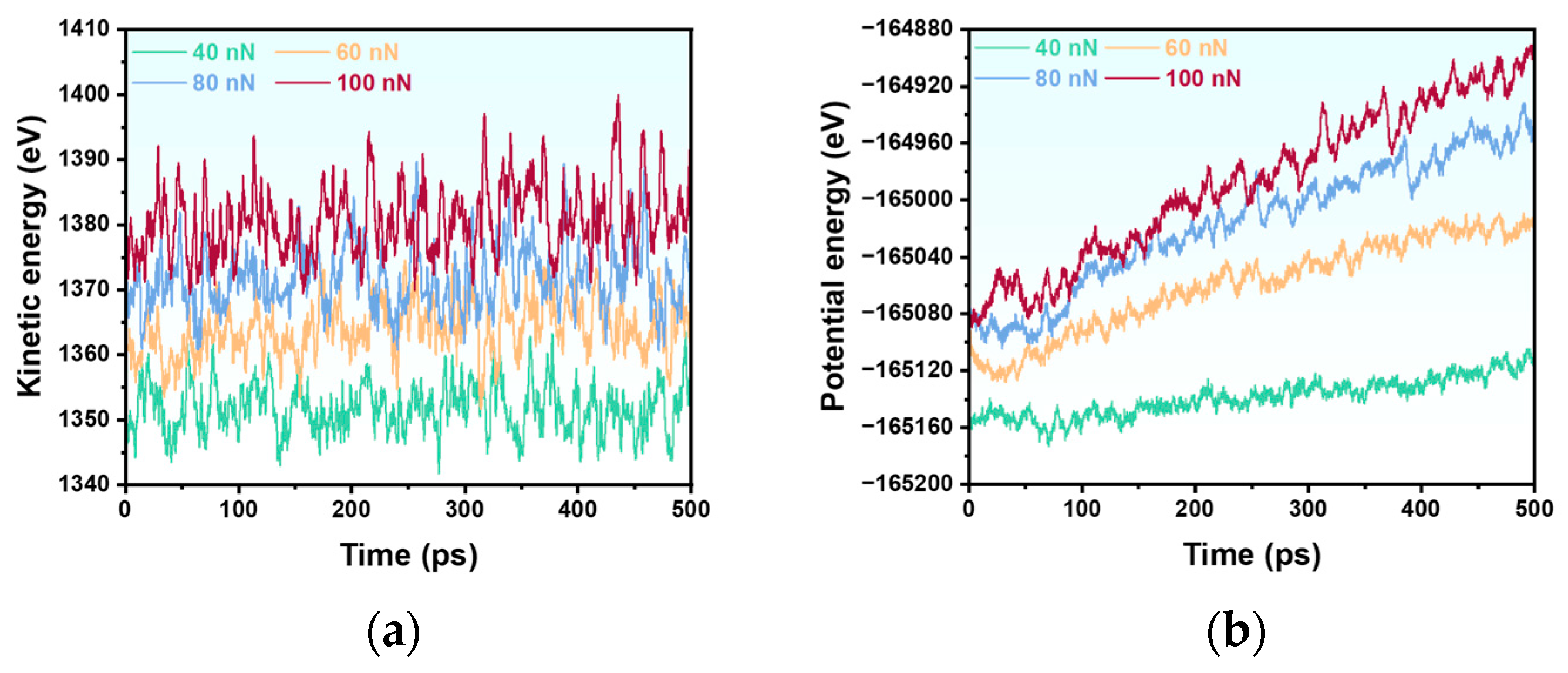
Figure 5 presents the energy evolution during the friction process, depicting (a) the kinetic energy and (b) the potential energy of the Fe–SiO2 interface under varying normal loads. The kinetic energy exhibits a clear positive correlation with the applied load, increasing from approximately 1350 eV at 40 nN to 1360 eV at 60 nN, 1367 eV at 80 nN, and 1379 eV at 100 nN. Notably, the fluctuation amplitude of kinetic energy becomes more pronounced with increasing load, indicating enhanced atomic disorder and more intense thermal-mechanical motion at the sliding interface. Meanwhile, the potential energy curve shifts to higher energy levels as the load increases, with the most significant rise observed between 40 nN and 60 nN. This substantial increase in potential energy suggests considerable atomic rearrangement and accumulation of lattice defects during the initial loading stage [34]. The subsequent elevation from 80 nN to 100 nN is relatively modest, implying that the interface may be approaching a saturation state in terms of defect concentration or structural transformation. The complementary evolution of kinetic and potential energy reflects the energy redistribution process during frictional sliding, where mechanical work is continuously converted into both thermal motion and structural disorder within the interfacial region.
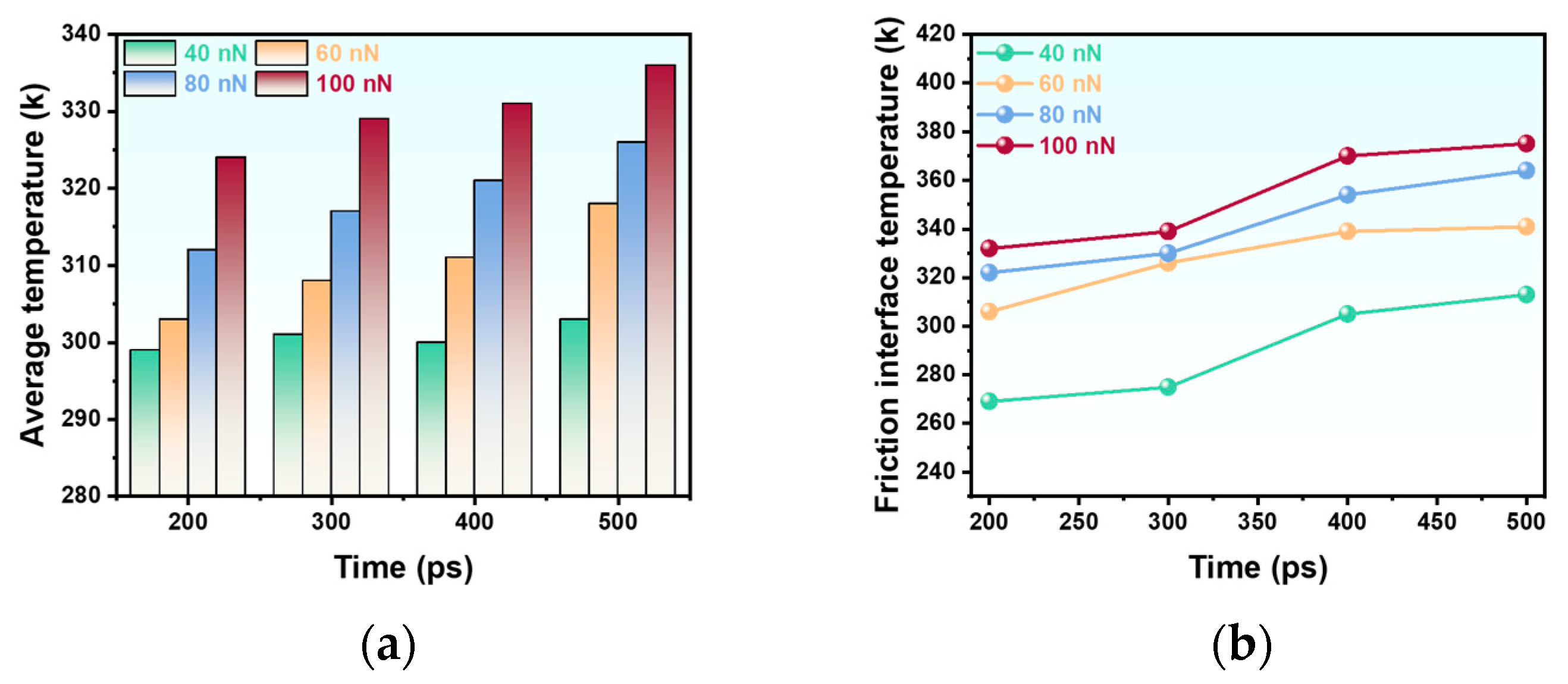
In Figure 6a, the average system temperature extracted at 200, 300, 400, and 500 ps demonstrates a consistent positive correlation with the applied load. Notably, for loads exceeding 60 nN, the temperature exhibits a continuous rise over time, with the incremental differences between loads remaining nearly constant across different time intervals. This suggests a stable, load-dependent thermal input mechanism dominates at higher contact pressures. In contrast, at 40 nN, the temperature increase is negligible, with the system temperature remaining essentially constant between 300 and 400 ps, indicating that the frictional energy dissipation at this threshold load is insufficient to drive significant bulk heating. Figure 6b reveals a more pronounced thermal response at the friction interface, defined within a 5 Å depth from the Fe surface. The interface temperature increases markedly with load, exhibiting the most significant jump between 40 nN and 60 nN. This abrupt rise implies a possible transition in the dominant friction mechanism, such as enhanced plastic dissipation or the onset of localized adhesive junction shearing. Beyond 60 nN, the rate of temperature increase diminishes, suggesting a saturation effect in interfacial heat generation or improved heat dissipation into the substrate at severe loading conditions. The stark contrast between the moderate bulk heating and the extreme interfacial temperature rise highlights the highly localized nature of frictional energy dissipation, emphasizing that global temperature measurements significantly underestimate the thermal severity at the actual sliding interface.
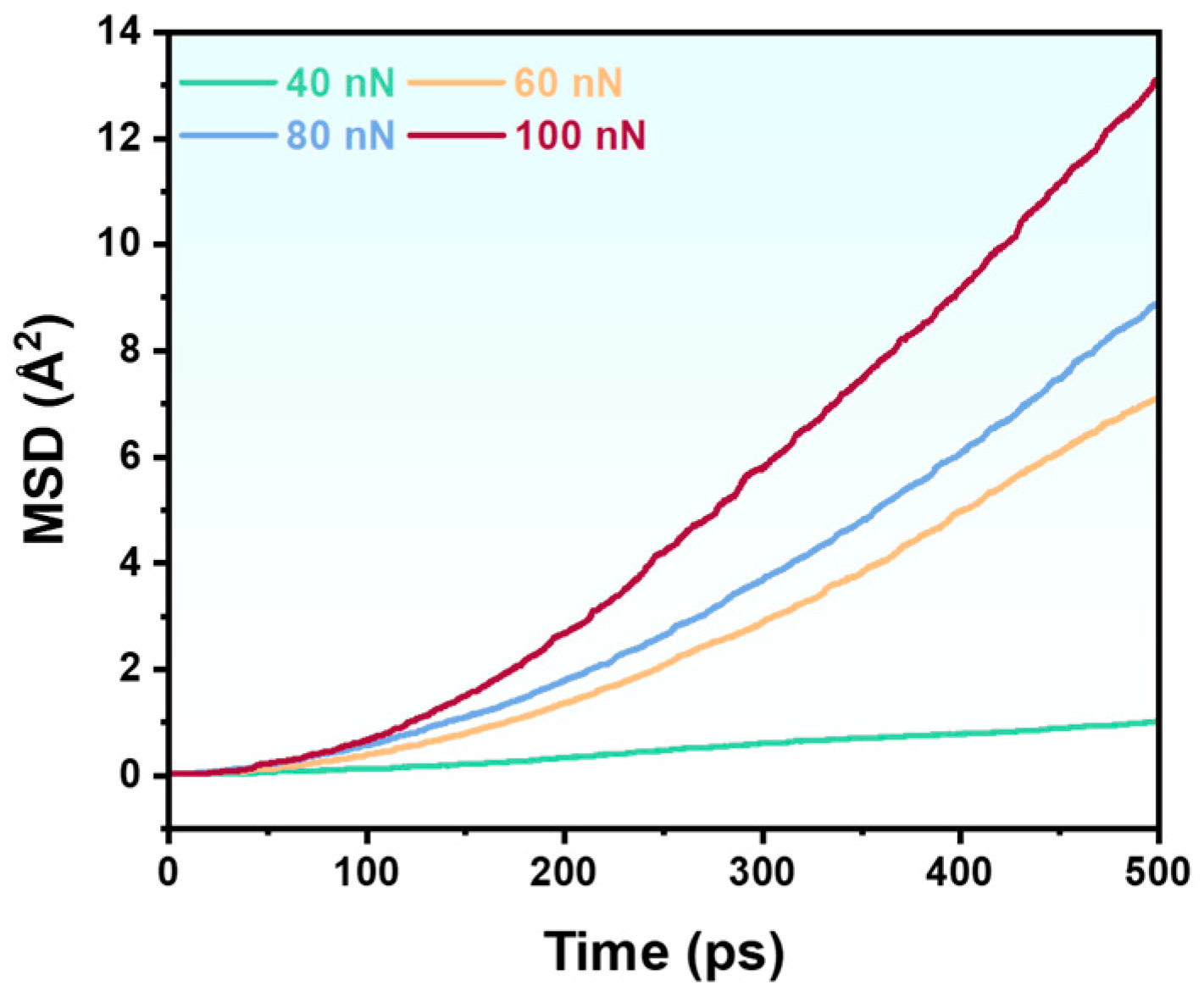
Figure 7 illustrates the evolution of the mean square displacement (MSD) [35] of Fe atoms during the friction process under varying normal loads, providing critical insights into atomic-scale plastic flow and deformation mechanisms. A pronounced load-dependent behavior is observed, with the MSD values exhibiting a monotonic increase as the normal load intensifies from 40 nN to 100 nN. The most significant enhancement in atomic mobility occurs between 40 nN and 60 nN, indicating a threshold-like response where interfacial plasticity initiates more extensively beyond a critical contact pressure. This accelerated rise in MSD under elevated loads reflects greater cumulative shear-induced atomic rearrangements and increasingly irreversible plastic deformation [36]. The enhanced atomic mobility signifies a transition from predominantly elastic or mildly plastic regimes to widespread dislocation-mediated slip or even localized amorphization at the interface. The continuous increase in MSD with load correlates strongly with the observed rise in friction coefficient (Figure 1), interfacial strain localization (Figure 4), and asymmetric pile-up morphology (Figure 3), suggesting that atomic diffusion and plastic flow constitute the fundamental mechanisms governing macroscopic tribological behavior. Furthermore, the increasing trend of MSD with load underscores the role of severe shear deformation in facilitating atomic transport, which is further amplified by frictional heating as evidenced in Figure 6. The interplay between mechanical forcing and thermal activation promotes non-affine atomic motions, leading to permanent deformation and microstructural evolution in the subsurface region. The MSD evolution not only quantifies the degree of plasticity but also serves as a key indicator of the transition from mild to severe wear regimes, providing atomistic validation of the load-dependent damage accumulation in the Fe substrate.

3.2. Effect of Sliding Velocities on the Tribological Properties

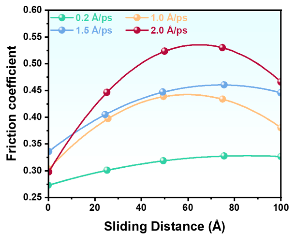
Figure 8 depicts the evolution of the friction coefficient at the Fe–SiO2 interface under varying sliding velocities (applied load = 60 nN), revealing a strong velocity-dependent strengthening behavior. The overall trend demonstrates a positive correlation between the friction coefficient and sliding velocity, indicating a transition in the dominant energy dissipation mechanism as a function of speed. At the lowest velocity of 0.2 Å/ps, the friction coefficient remains remarkably low throughout the sliding process, suggesting a quasi-static deformation regime where interfacial adhesion and plastic shearing are limited. In contrast, higher velocities (1.0, 1.5, and 2.0 Å/ps) exhibit significant instability during the initial sliding stage, reflecting rapid microstructural evolution and transient adhesive interactions. Particularly at 2.0 Å/ps, the friction coefficient displays the steepest growth rate, reaching a pronounced peak at a sliding distance of approximately 55 Å before undergoing rapid decay. This behavior indicates a critical transition in interfacial dynamics, likely associated with the onset of severe plastic flow, strain localization, or thermal softening effects. Similar though less dramatic trends are observed at 1.0 and 1.5 Å/ps, suggesting a universal velocity-activated mechanism across intermediate and high speeds.
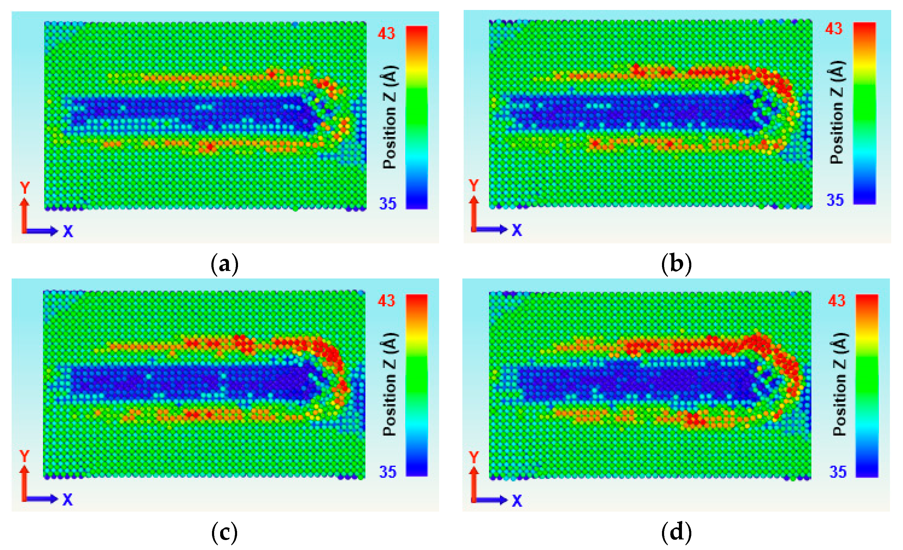
Figure 9 exhibits the wear scar morphologies and corresponding atomic height distribution on the Fe surface within the range of 35–43 Å under varied sliding velocities, providing critical insights into velocity-dependent wear mechanisms. At the lowest velocity of 0.2 Å/ps, only minor atomic pile-up is observed, indicating limited plastic deformation and a mild wear regime dominated by elastic and reversible microstructural changes. As the sliding velocity increases, a pronounced escalation in atomic accumulation is evident, with the most severe pile-up occurring at 2.0 Å/ps. This heightened deformation suggests a transition to a severe wear regime where enhanced strain rate sensitivity, adiabatic heating, and insufficient stress relaxation promote extensive plastic flow and material redistribution. Notably, the pile-up morphology exhibits significant spatial asymmetry, with the upper section of the wear scar demonstrating substantially greater accumulation compared to the lower region. This asymmetry likely arises from the combined effects of shear gradient localization, velocity-dependent strain partitioning, and progressive accumulation of plastic strain in the direction of sliding [37]. The pronounced velocity dependence of pile-up severity and asymmetry underscores the role of kinetic effects in controlling interfacial damage evolution, linking directly to the velocity-strengthening behavior of the friction coefficient observed in Figure 8.
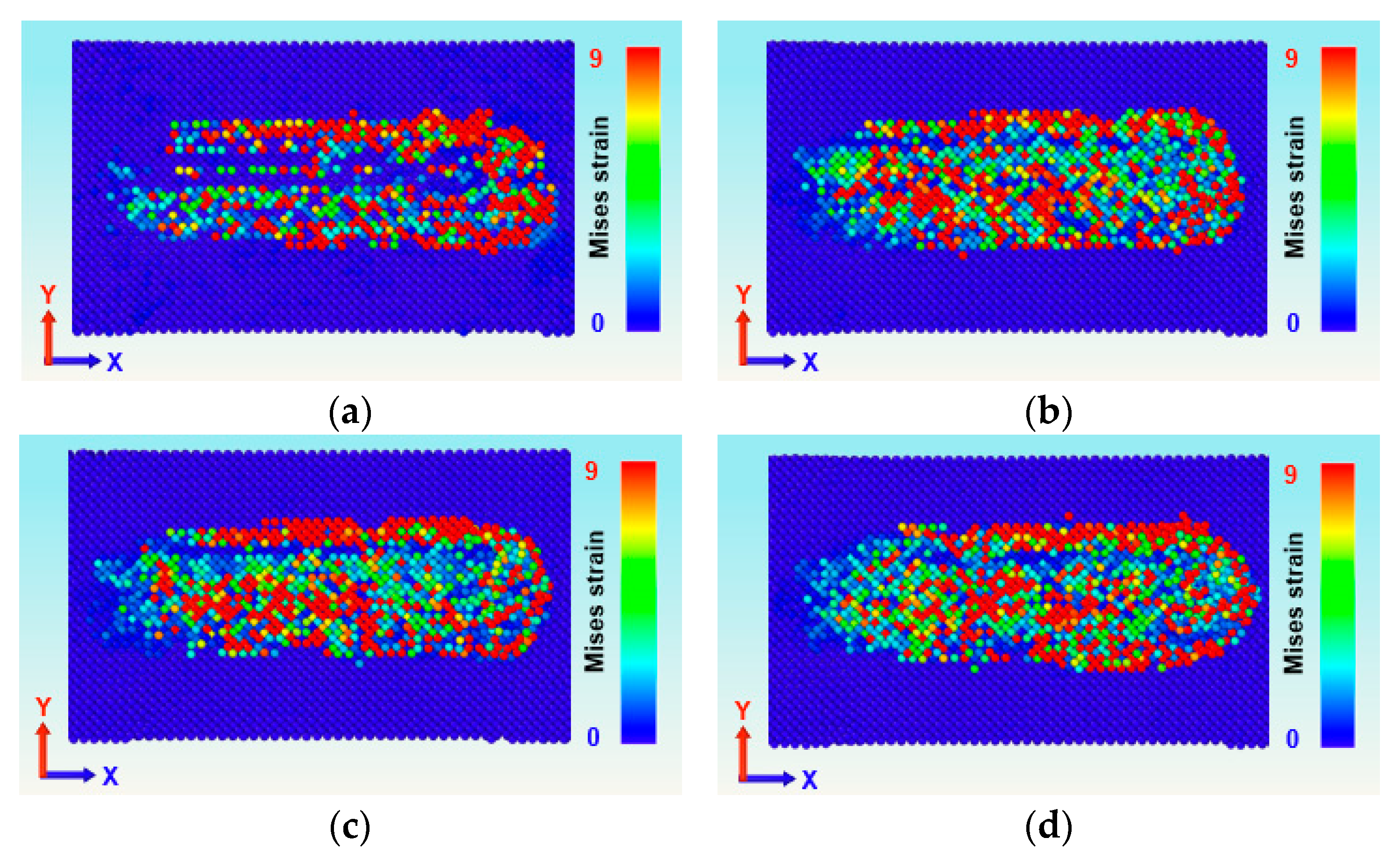
Figure 10 illustrates the distribution of von Mises equivalent strain within the Fe substrate under varying sliding velocities, revealing pronounced velocity-dependent plastic deformation characteristics. Under lower sliding velocities, the strain field remains relatively localized, confined to a narrow region beneath the contact interface. This suggests a quasi-static deformation regime where plastic flow is limited and strain gradients are steep. As the sliding velocity increases, a significant expansion in both the spatial extent and magnitude of the strain field is observed. The region of high equivalent strain propagates deeper into the substrate and spreads laterally, indicating enhanced plasticity and more extensive microstructural reorganization [38]. Notably, all strain distributions exhibit marked heterogeneity, with alternating bands of high and low strain intensity, reflecting the unstable and localized nature of plastic flow under high-strain-rate deformation.
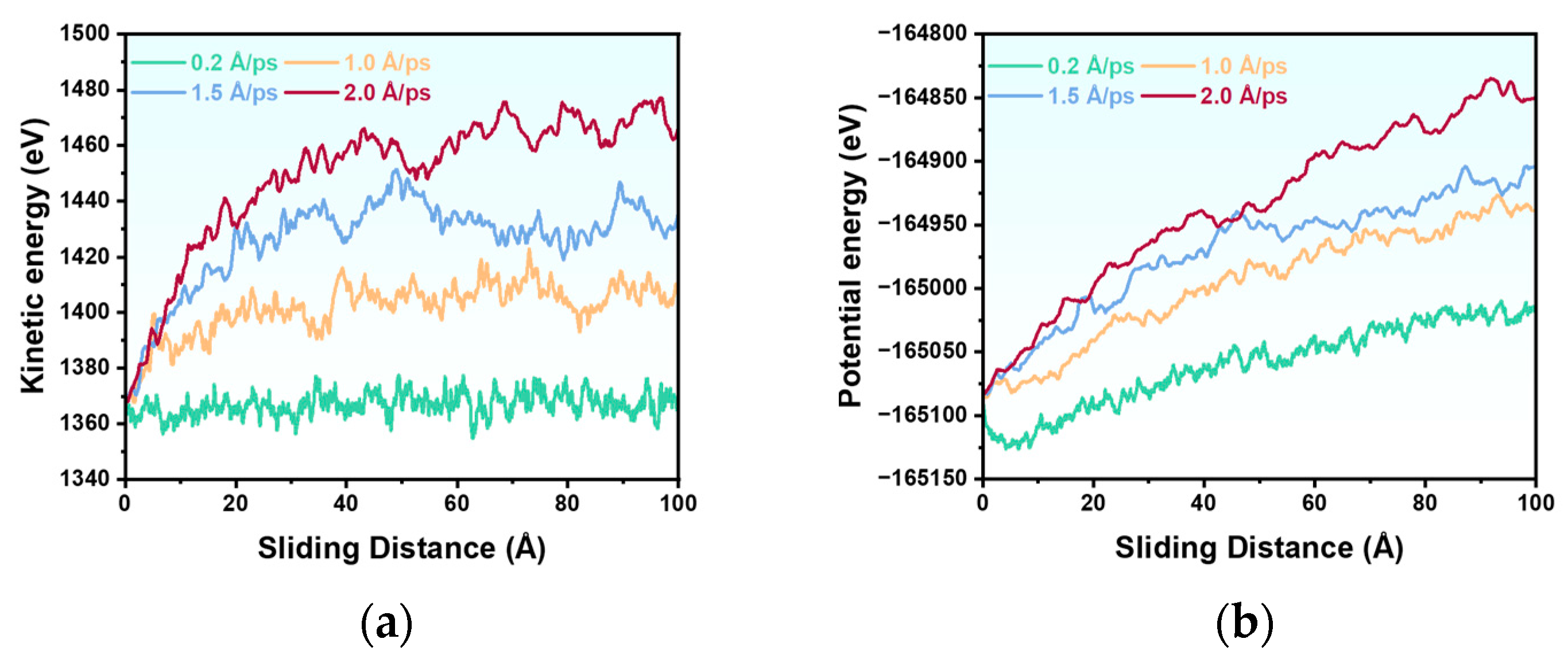
In Figure 11a, the kinetic energy exhibits a strong velocity dependence, increasing systematically with higher sliding speeds. At the lowest velocity of 0.2 Å/ps, the kinetic energy remains relatively constant with minor fluctuations, indicating limited thermal activation and quasi-static sliding conditions. In contrast, at elevated velocities, the kinetic energy demonstrates rapid growth during initial sliding, reaching a stable plateau at approximately 30 Å. This behavior suggests a transition to a thermally activated regime where frictional heating significantly enhances atomic vibrations and disorder at the interface. Figure 11b reveals that the potential energy shifts to higher absolute values with increasing velocity, accompanied by reduced fluctuation amplitudes. The upward shift in potential energy indicates accumulation of lattice defects, structural disordering, and enhanced atomic miscoordination at higher sliding speeds [39]. The suppression of fluctuations suggests that the system enters a more continuous plastic flow regime with reduced elastic recovery, as the interface undergoes progressive microstructural evolution under high-strain-rate deformation.
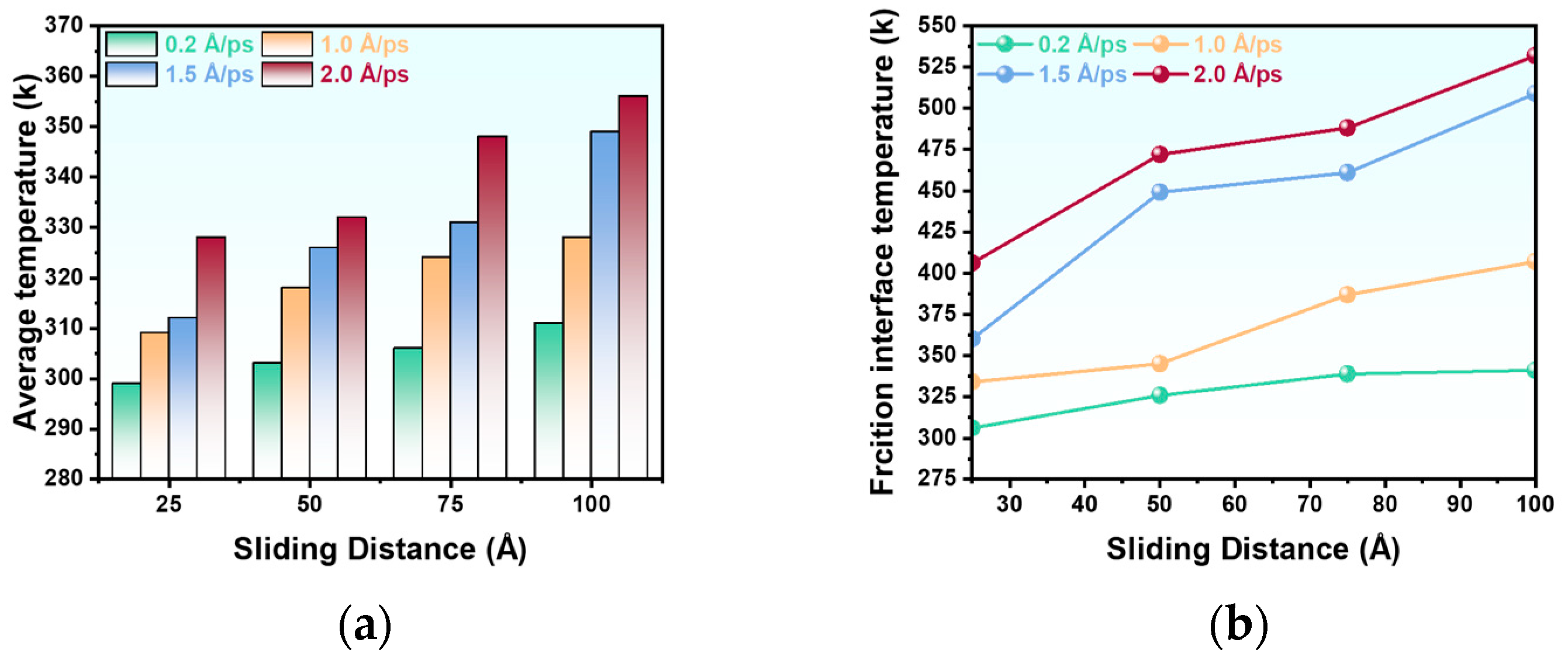
As depicted in Figure 12a, the average system temperature, extracted at sliding distances of 25, 50, 70, and 100 Å, exhibits a consistent positive correlation with both sliding velocity and cumulative sliding distance. Higher velocities generate significantly greater frictional heating, resulting in elevated global temperatures across all recorded intervals. This trend highlights the transition from quasi-isothermal conditions at lower speeds to pronounced thermomechanical coupling at higher velocities, where the limited timescale for heat dissipation leads to substantial bulk heating. Figure 12b reveals an even more pronounced thermal response at the friction interface, characterized within a confined 5 Å layer beneath the Fe surface. The interfacial temperature increases markedly with velocity, with the most significant jump observed between 1.0 and 1.5 Å/ps. This abrupt rise suggests a critical transition in the dominant heating mechanism, likely associated with the onset of severe plastic deformation, strain localization, and enhanced viscous dissipation within the interfacial layer [40]. Beyond 1.5 Å/ps, the rate of temperature increase diminishes, indicating a possible saturation in energy conversion efficiency or improved conductive heat transfer into the substrate under extreme sliding conditions. The stark contrast between the moderate bulk temperature rise and the extreme interfacial heating underscores the highly localized nature of frictional energy dissipation, emphasizing that global temperature measurements significantly underestimate the thermal severity at the actual sliding interface. This velocity-dependent thermal response correlates strongly with the observed evolution of kinetic energy and defect accumulation shown in Figure 11, suggesting that thermal softening and microstructural transformation play crucial roles in accommodating high-strain-rate deformation.
Figure 13 illustrates the evolution of the MSD of Fe atoms during the friction process under varying sliding velocities, revealing a distinctive velocity-dependent diffusion behavior characterized by critical transitions in atomic mobility. The overall trend demonstrates a positive correlation between MSD and sliding velocity, indicating enhanced atomic-scale plasticity and irreversible deformation at higher speeds. A particularly pronounced increase in MSD occurs within the velocity range of 0.2 to 1.0 Å/ps, suggesting a threshold-like transition from quasi-static sliding to a regime where strain rate sensitivity and thermal activation significantly promote atomic mobility. Notably, for velocities of 1.0, 1.5, and 2.0 Å/ps, the MSD curves exhibit remarkable convergence during the initial sliding stage (up to ~60 Å), indicating that short-term deformation mechanisms remain relatively similar across this velocity range. Beyond this critical sliding distance, the curves diverge systematically, with higher velocities producing progressively greater MSD accumulation. This delayed divergence suggests that velocity-dependent effects become dominant only after sufficient cumulative shear strain has been applied, potentially corresponding to the establishment of a steady-state tribological layer or the activation of additional plasticity mechanisms. The transition in MSD evolution around 60 Å coincides with the observed stabilization of kinetic energy (Figure 11) and the saturation of interfacial temperature (Figure 12), implying the formation of a dynamically stable interfacial structure that mediates subsequent deformation. The post-60 Å divergence highlights how higher velocities enhance long-term atomic mobility through continued damage accumulation, thermal softening, and microstructural refinement.

4. Conclusions

This study employs MD simulations to comprehensively analyze the microscopic response of the Fe–SiO2 friction interface under varying normal loads and sliding velocities. The main conclusions are as follows:
(1)
The coefficient of friction shows strong dependence on both normal load and sliding velocity, with a transition from elastic-dominated deformation under low load/velocity to severe plastic deformation under high-load/velocity conditions.
(2)
Interfacial plastic deformation intensifies with increasing load, exhibiting asymmetric atomic pile-up and expansion of strain field from localized to global distribution.
(3)
Energy analysis reveals significant conversion of mechanical work to heat and defects, with the most dramatic potential energy change occurring at 40–60 nN, indicating critical defect accumulation.
(4)
Temperature distribution shows high localization at the interface, with the most significant thermal response occurring between 1.0–1.5 Å/ps, suggesting a transition in heating mechanisms.
(5)
Atomic diffusion displays velocity-dependent staging, with MSD showing threshold behavior at 0.2–1.0 Å/ps and delayed divergence beyond 60 Å sliding distance for higher velocities.
These atomic-scale insights offer valuable perspectives for the design of abrasion-resistant agricultural tillage tools. The observation that severe plastic deformation and thermal effects become markedly more pronounced within specific parameter ranges underscores the necessity of employing materials with high mechanical strength and thermal stability to withstand demanding operational conditions. Furthermore, the detailed understanding of the running-in period and the transitions in deformation mechanisms provides a scientific basis for optimizing tool geometries and operational parameters.

Author Contributions

Conceptualization, X.J. and G.W.; methodology, G.W.; software, G.H.; validation, O.C., Q.C. and C.P.; formal analysis, X.J.; investigation, X.J.; resources, G.W.; data curation, Q.C. and O.C.; writing—original draft preparation, X.J., G.H. and G.W.; writing—review and editing, X.J., Q.C. and G.W.; visualization, Q.C.; supervision, C.P.; project administration, C.P.; funding acquisition, X.J. and G.W. All authors have read and agreed to the published version of the manuscript.

Funding

This research was funded by National Natural Science Foundation of China, grant number 52505192, Natural Science Foundation of Jiangsu Province, grant number BK20250710, Wuxi Soft Science Research Project, grant number KX-25-B30 and Natural Science Research Project of Wuxi Institute of Technology, grant number ZK2023010.

Institutional Review Board Statement

Not applicable.

Informed Consent Statement

Not applicable.

Data Availability Statement

The original contributions presented in this study are included in the article. Further inquiries can be directed to the corresponding author.

Conflicts of Interest

The authors declare no conflicts of interest.

References

  1. Peng, Y.; Jin, T.; Ding, J.; Shi, Y.; Wang, Y.; Zhang, W. Integrated manufacturing of heterogeneous-material tillage wear-resisting parts based on selective laser melting. J. Alloys Compd. 2025, 1014, 178723. [Google Scholar] [CrossRef]
  2. Wang, Y.; Li, D.; Nie, C.; Gong, P.; Yang, J.; Hu, Z.; Li, B.; Ma, M. Research progress on the wear resistance of key components in agricultural machinery. Materials 2023, 16, 7646. [Google Scholar] [CrossRef]
  3. Wei, M.; Zhu, L.; Luo, F.; Zhang, J.-W.; Dong, X.-W.; Jen, T.-C. Share-soil interaction load and wear at various tillage conditions of a horizontally reversible plough. Comput. Electron. Agric. 2019, 162, 21–30. [Google Scholar] [CrossRef]
  4. Malvajerdi, A.S. Wear and coating of tillage tools: A review. Heliyon 2023, 9, e16669. [Google Scholar] [CrossRef]
  5. Aramide, B.; Pityana, S.; Sadiku, R.; Jamiru, T.; Popoola, P. Improving the durability of tillage tools through surface modification—A review. Int. J. Adv. Manuf. Technol. 2021, 116, 83–98. [Google Scholar] [CrossRef]
  6. Wang, X.; Zhang, S.; Du, R.; Zhou, H.; Ji, J. Recent sdvances in biomimetic methods for tillage resistance reduction in agricultural soil-engaging tools. Agronomy 2024, 14, 2163. [Google Scholar] [CrossRef]
  7. Xu, Z.; Qi, H.; Gao, P.; Wang, S.; Liu, X.; Ma, Y. Biomimetic design of soil-engaging components: A review. Biomimetics 2024, 9, 358. [Google Scholar] [CrossRef]
  8. Barzegar, M.; Hashemi, S.J.; Nazokdast, H.; Karimi, R. Evaluating the draft force and soil-tool adhesion of a UHMW-PE coated furrower. Soil Tillage Res. 2016, 163, 160–167. [Google Scholar] [CrossRef]
  9. Dushyant, S.; Ramesh Kumar, S.; Narendra Singh, C.; Dilip, J.; Anand Kumar, V.; Ashis Kumar, B.; Anurag, P. Metallurgical requirements of soil engaging component under conservation agriculture practices. J. Agric. Eng. 2022, 59. [Google Scholar] [CrossRef]
  10. Zheng, X.; Sun, B.; Gao, G.; Wang, H.; Qi, Y.; Zhao, G.; Ren, J.; Zhang, Y. Tribological performance and failure mechanisms of soil-engaging components with brazed WC–Ni coatings. Tribol. Int. 2026, 214, 111139. [Google Scholar] [CrossRef]
  11. Pásthy, L.; József Farkas, Z.; Haba, T.; Tamás, K. Development of a multi-way coupled discrete-finite element method simulation procedure for modelling soil-passive vibration tool interaction. Comput. Electron. Agric. 2024, 216, 108459. [Google Scholar] [CrossRef]
  12. Tekeste, M.Z.; Balvanz, L.R.; Hatfield, J.L.; Ghorbani, S. Discrete element modeling of cultivator sweep-to-soil interaction: Worn and hardened edges effects on soil-tool forces and soil flow. J. Terramechanics 2019, 82, 1–11. [Google Scholar] [CrossRef]
  13. Sadek, M.A.; Chen, Y. Feasibility of using PFC3D to simulate soil flow resulting from a simple soil-engaging tool. Trans. ASABE 2015, 58, 987–996. [Google Scholar] [CrossRef]
  14. Haynes, R.J. A contemporary overview of silicon availability in agricultural soils. J. Plant Nutr. Soil Sci. 2014, 177, 831–844. [Google Scholar] [CrossRef]
  15. Ren, J.; He, H.; Lau, K.-C.; Senetakis, K. Influence of iron oxide coating on the tribological behavior of sand grain contacts. Acta Geotech. 2022, 17, 2907–2929. [Google Scholar] [CrossRef]
  16. Zhao, Z.; Wu, M.; Jiang, X. A review of contact models’ properties for discrete element simulation in agricultural engineering. Agriculture 2024, 14, 238. [Google Scholar] [CrossRef]
  17. Dong, Y.; Li, Q.; Martini, A. Molecular dynamics simulation of atomic friction: A review and guide. J. Vac. Sci. Technol. A 2013, 31, 030801. [Google Scholar] [CrossRef]
  18. Komanduri, R.; Chandrasekaran, N.; Raff, L.M. Molecular dynamics simulation of atomic-scale friction. Phys. Rev. B 2000, 61, 14007–14019. [Google Scholar] [CrossRef]
  19. Zhang, Y.; Zhang, Z.; Guo, Y.; Robertson, J.; Wu, S.; Liu, S.; Sun, Y. Recent advances in molecular dynamics simulations for dry friction on rough substrate. J. Phys. D Appl. Phys. 2024, 57, 473003. [Google Scholar] [CrossRef]
  20. Pan, A.; Wang, W.; Xie, J.; Zhang, H.; Hao, S. Molecular dynamics simulations of interface structure and deformation mechanisms in metal/ceramic composites under tension. Mech. Mater. 2023, 184, 104688. [Google Scholar] [CrossRef]
  21. Wang, J.; Xing, Z.; Zhu, J.; Li, H.; Han, Z.; Ren, H.; Li, Q. Adhesion-diffusion behavior and interfacial degradation mechanism of copper–aluminum under current-carrying friction conditions. J. Phys. D Appl. Phys. 2025, 58, 205502. [Google Scholar] [CrossRef]
  22. Lenzi, V.; Marques, L. Molecular dynamics simulation of Ti metal cutting using a TiN: Ag self-lubricating coated tool. Materials 2023, 16, 1344. [Google Scholar] [CrossRef]
  23. Plimpton, S. Fast parallel algorithms for short-range molecular dynamics. J. Comput. Phys. 1995, 117, 1–19. [Google Scholar] [CrossRef]
  24. Batcho, P.F.; Schlick, T. Special stability advantages of position-Verlet over velocity-Verlet in multiple-time step integration. J. Chem. Phys. 2001, 115, 4019–4029. [Google Scholar] [CrossRef]
  25. Toprak, K. Understanding neural network tuned Langevin thermostat effect on predicting thermal conductivity of graphene-coated copper using nonequilibrium molecular dynamics simulations. Model. Simul. Mater. Sci. Eng. 2024, 32, 025008. [Google Scholar] [CrossRef]
  26. Shao, W.; Shi, Z.; Rao, L.; Zhang, S.; Xing, X.; Zhou, Y.; Yang, Q. High-temperature sliding friction behavior of amorphous carbon films: Molecular dynamics simulation. Langmuir 2020, 36, 15319–15330. [Google Scholar] [CrossRef]
  27. Duan, L.; Liu, Y. Relationships between elastic constants and EAM/FS potential functions for cubic crystals. Acta Met. Sin 2020, 56, 112–118. [Google Scholar] [CrossRef]
  28. Hoang, V.V. Molecular dynamics simulation of amorphous SiO2 nanoparticles. J. Phys. Chem. B 2007, 111, 12649–12656. [Google Scholar] [CrossRef]
  29. Deb Nath, S.K. Study of the effect of sizes on the structural properties of SiO2 glass by molecular dynamics simulations. J. Non-Cryst. Solids 2013, 376, 50–60. [Google Scholar] [CrossRef]
  30. Liang, T.; Zhou, M.; Zhang, P.; Yuan, P.; Yang, D. Multilayer in-plane graphene/hexagonal boron nitride heterostructures: Insights into the interfacial thermal transport properties. Int. J. Heat Mass Transfer 2020, 151, 119395. [Google Scholar] [CrossRef]
  31. Zhao, C.; Yao, M.; Han, X.; Qi, W.; Su, L.; Fu, R.; Gao, F. Temperature distribution and COF change of C/C-SiC friction pair. Ind. Lubr. Tribol. 2025. [Google Scholar] [CrossRef]
  32. Chandross, M.; Argibay, N. Friction of metals: A review of microstructural evolution and nanoscale phenomena in shearing contacts. Tribol. Lett. 2021, 69, 119. [Google Scholar] [CrossRef]
  33. Xu, L.-Z.; Qiao, G.-Y.; Ma, Y.-L.; Gu, Y.; Xu, K.; Chen, X.-W.; Xiao, F.-R. Plastic damage mechanism and grain orientation evolution along the thickness direction in heavy-walled submarine pipelines during the progressive forming process. Mater. Sci. Eng. A 2025, 919, 147524. [Google Scholar] [CrossRef]
  34. Zhang, Y.; Stocks, G.M.; Jin, K.; Lu, C.; Bei, H.; Sales, B.C.; Wang, L.; Béland, L.K.; Stoller, R.E.; Samolyuk, G.D.; et al. Influence of chemical disorder on energy dissipation and defect evolution in concentrated solid solution alloys. Nat. Commun. 2015, 6, 8736. [Google Scholar] [CrossRef]
  35. Vural, D.; Hong, L.; Smith, J.C.; Glyde, H.R. Long-time mean-square displacements in proteins. Phys. Rev. E 2013, 88, 052706. [Google Scholar] [CrossRef]
  36. Bhuiyan, F.H.; Li, Y.-S.; Kim, S.H.; Martini, A. Shear-activation of mechanochemical reactions through molecular deformation. Sci. Rep. 2024, 14, 2992. [Google Scholar] [CrossRef]
  37. Adam, J.; Urai, J.L.; Wieneke, B.; Oncken, O.; Pfeiffer, K.; Kukowski, N.; Lohrmann, J.; Hoth, S.; van der Zee, W.; Schmatz, J. Shear localisation and strain distribution during tectonic faulting—New insights from granular-flow experiments and high-resolution optical image correlation techniques. J. Struct. Geol. 2005, 27, 283–301. [Google Scholar] [CrossRef]
  38. Ulyanenkov, A.; Darowski, N.; Grenzer, J.; Pietsch, U.; Wang, K.H.; Forchel, A. Evaluation of strain distribution in freestanding and buried lateral nanostructures. Phys. Rev. B 1999, 60, 16701–16714. [Google Scholar] [CrossRef]
  39. Zhao, S.; Chen, D.; Yeli, G.; Kai, J.J. Atomistic insight into the effects of order, disorder and their interface on defect evolution. J. Alloys Compd. 2021, 859, 157770. [Google Scholar] [CrossRef]
  40. Karantza, K.D.; Manolakos, D.E. A Review on the Adiabatic Shear Banding Mechanism in Metals and Alloys Considering Microstructural Characteristics, Morphology and Fracture. Metals 2023, 13, 1988. [Google Scholar] [CrossRef]
Figure 1. Schematic of the MD friction simulation model for the Fe–SiO2 system.
Coatings 15 01252 g001
Figure 2. Friction coefficient of the Fe–SiO2 interface under varied loads.
Coatings 15 01252 g002
Figure 3. Wear scar morphologies on the Fe surface under varied applied loads. (a) Load = 40 nN; (b) Load = 60 nN; (c) Load = 80 nN; (d) Load = 1000 nN.
Coatings 15 01252 g003
Figure 4. Distribution of von Mises equivalent strain in the Fe substrate under different loads. (a) Load = 40 nN; (b) Load = 60 nN; (c) Load = 80 nN; (d) Load = 1000 nN.
Coatings 15 01252 g004
Figure 5. Energy evolution during friction: (a) kinetic energy and (b) potential energy of the Fe–SiO2 interface under different loads.
Coatings 15 01252 g005
Figure 6. Temperature evolution under different loads: (a) average temperature of the entire system and (b) localized temperature at the friction interface.
Coatings 15 01252 g006
Figure 7. Evolution of the MSD during the friction process under different loads.
Coatings 15 01252 g007
Figure 8. Friction coefficient of the Fe–SiO2 interface under varied velocities.
Coatings 15 01252 g008
Figure 9. Wear scar morphologies on the Fe surface under varied velocities. (a) Velocity = 0.2 Å/ps; (b) Velocity = 1.0 Å/ps; (c) Velocity = 1.5 Å/ps; (d) Velocity = 2.0 Å/ps.
Coatings 15 01252 g009
Figure 10. Distribution of von Mises equivalent strain in the Fe substrate under different velocities. (a) Velocity = 0.2 Å/ps; (b) Velocity = 1.0 Å/ps; (c) Velocity = 1.5 Å/ps; (d) Velocity = 2.0 Å/ps.
Coatings 15 01252 g010
Figure 11. Energy evolution during friction: (a) kinetic energy and (b) potential energy of the Fe–SiO2 interface under different velocities.
Coatings 15 01252 g011
Figure 12. Temperature evolution under different velocities: (a) average temperature of the entire system and (b) localized temperature at the friction interface.
Coatings 15 01252 g012
Figure 13. Evolution of the MSD during the friction process under different velocities.
Coatings 15 01252 g013
Table 1. LJ potential energy parameters.
Interaction Pairδ/(Å)ε/(eV)
Fe-Si3.21040.0031348
Fe-O2.85620.0012
Disclaimer/Publisher’s Note: The statements, opinions and data contained in all publications are solely those of the individual author(s) and contributor(s) and not of MDPI and/or the editor(s). MDPI and/or the editor(s) disclaim responsibility for any injury to people or property resulting from any ideas, methods, instructions or products referred to in the content.