1. Introduction
Large-span dome roofs are widely adopted in petrochemical and bulk material storage facilities, such as silos and oil tanks, due to their superior load-bearing capacity and spatial efficiency [
1,
2]. As the scale of industrial production expands, the demand for these high-capacity storage structures continues to grow. To ensure structural stability under large-span conditions—defined for temporary structures as formwork support systems exceeding an 18 m span [
3]—roof systems typically employ dome or reticulated shell configurations. Whether utilizing metallic or reinforced concrete composite systems, these roofs are critical for the safety and serviceability of industrial facilities [
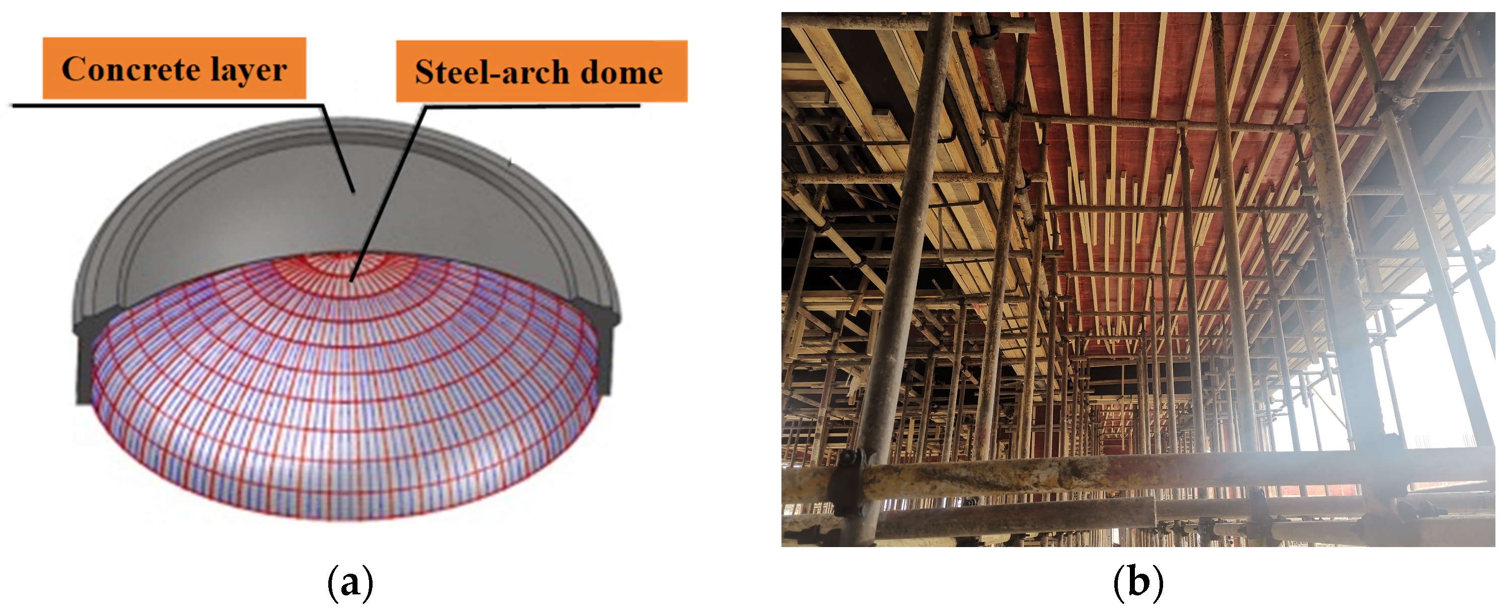
4]. Consequently, the rational design of temporary formwork and support systems is indispensable for maintaining geometric accuracy and structural integrity during concrete casting. In petrochemical applications, dome roofs are typically installed atop cylindrical storage tanks, frequently utilizing single-layer steel domes as the primary roof-supporting system [
5]. These systems not only provide temporary support for formwork and fresh concrete loads during construction but also function as isolation or pressure-retaining boundaries during service operations [
6] (
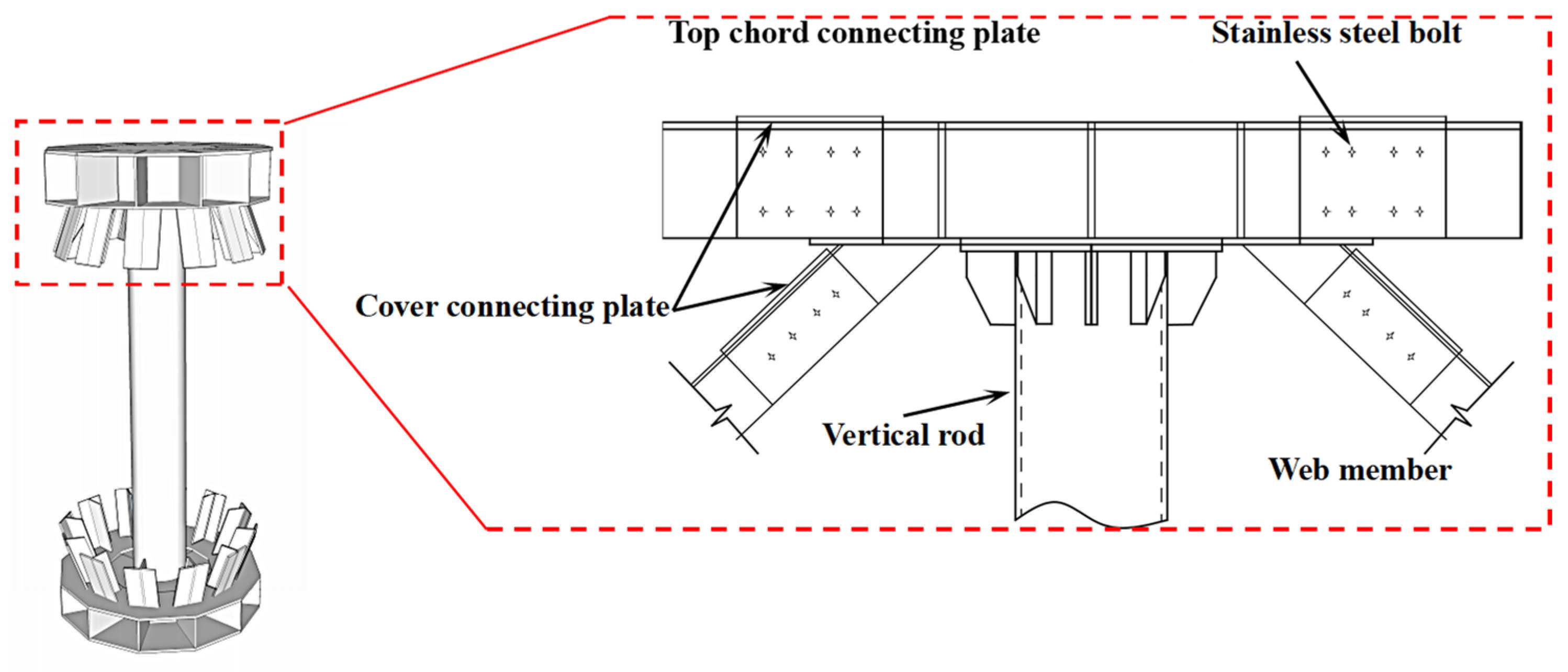
Figure 1a). This configuration has been successfully implemented across diverse engineering applications, including steel liner domes for nuclear containment structures [
7] and large public building roofs, such as the Atlanta Mosque [
8].
However, constructing large-span dome roofs is typically constrained by challenging conditions, including elevated working heights, restricted sites, and limited operational space. Consequently, roof-level formwork erection and concrete casting are characterized by heightened safety risks, complex procedures, and significant logistical challenges [
9]. In practice, removable temporary support platforms are frequently employed to satisfy load-bearing requirements during the construction stage. As storage diameters continue to increase, conventional construction schemes often rely on central derricks or large-scale steel support systems to enhance global stiffness and load-carrying capacity; this inevitably leads to labor-intensive installation, extensive space occupation, high costs, and pronounced safety risks associated with high-altitude operations. When traditional steel tubular scaffolding systems are utilized [
10,
11], the dense frame spacing restricts working space, while intricate erection and dismantling processes demand substantial material and labor inputs, hindering the balance between economic efficiency and construction safety. Conversely, cantilever-type support systems are limited by span length and structural configuration; their load-bearing capacity often fails to meet dome construction demands, thereby increasing construction control difficulties. Furthermore, platform systems supported by steel lattice columns typically necessitate additional concrete foundations and reinforcement, which not only escalate costs but also introduce potential risks to overall structural stability. Overall, while existing steel lattice column platforms and scaffolding systems can adequately meet basic load-bearing demands, they remain hindered by inherent limitations, including complex configurations, extended construction periods, high costs, poor adaptability, and limited reusability.
Extensive research has been conducted to mitigate the challenges and safety risks associated with high-altitude operations during large-span dome construction. For instance, Lu et al. [
12] proposed an integral lifting truss-based falsework system that eliminates the need for high-altitude erection by assembling the large-span steel truss at ground level. Liang et al. [
13] addressed the incompatibility between wall slip-form construction and dome formwork installation by employing a synchronously lifted radial steel truss platform, thereby significantly reducing construction risks. Nie et al. [
14] introduced permanent stay-in-place metal mesh formwork for liquefied natural gas storage tanks to enhance construction efficiency, while Jin et al. [
15] designed an adjustable steel truss-supported roof formwork system adaptable to varying silo diameters. Furthermore, conventional steel tubular scaffolding systems remain widely utilized due to their favorable global stability and construction convenience [
16]. Liu et al. [
17] experimentally investigated the load-carrying capacity and stiffness characteristics of disk-lock steel tubular scaffolding under horizontal loads, revealing failure modes across various structural parameters. Similarly, Meng et al. [
18] conducted full-scale static tests and finite element analyses on a modular dome-type rigid platform for large-diameter silos, providing a reliable basis for engineering applications. However, a critical limitation of these aforementioned studies is their primary focus on construction techniques, conceptual designs, and static load-bearing capacities. Systematic investigations into the dynamic mechanical behavior of these temporary systems remain largely insufficient. Specifically, comprehensive analyses regarding progressive deformation, mechanical responses under complex staged loading scenarios (e.g., concrete pouring), and intricate internal force distributions within the spatial framing members are rarely addressed.
In recent years, modular and prefabricated construction methods have attracted increasing attention for temporary structural systems, primarily to improve construction efficiency, reduce labor intensity, and enhance sustainability. Compared to conventional steel support systems, modular aluminum alloy systems offer notable advantages, including a lightweight nature, superior corrosion resistance, and high reusability [
19]. However, the practical application of modular aluminum alloy systems in large-span dome formwork supports remains relatively limited. Existing studies focus predominantly on material properties or the mechanical behavior of individual components; the global structural performance under staged construction loads has not yet been systematically investigated [
20,
21,
22]. Overall, current research on temporary support structures concentrates heavily on steel support towers, scaffolding systems, and conventional formwork frames, paying insufficient attention to large-span dome formwork systems characterized by complex spatial load-transfer mechanisms. Specifically, systematic studies examining the deformation evolution, internal force redistribution, and construction-stage safety of modular aluminum alloy dome formwork systems remain lacking, thereby constraining their broader engineering application.
Furthermore, deformation control during the concrete casting stage represents a critical challenge in dome formwork construction [
23]. Due to the large spans of dome structures and the relatively slender nature of formwork members, significant deflections and localized stress concentrations are prone to occur under construction loads, particularly in ring beams, radial trusses, and key connection regions. Introducing externally applied prestressing establishes a favorable initial internal force state, which enhances global stiffness and controls deformation. For instance, in reciprocal spatial structures, prestressing has been applied via flexible cables routed through struts beneath rigid beams. By investigating the interactions among these beam-strut-cable members, studies have demonstrated that prestressing effectively optimizes load-transfer paths, increasing global stiffness by 17% and reducing steel consumption by 12% [
24]. Similarly, in beam string structures, prestressing is typically introduced by tensioning bottom cables connected to upper compression members (e.g., steel tubes or aluminum blocks) [
25]. This active load-bearing mechanism effectively controls structural deflections while providing significant material-saving benefits. Although these prestressing techniques have been successfully validated in permanent spatial structures, their application in temporary modular formwork systems for large-span dome construction remains insufficiently explored. Therefore, systematically evaluating the effectiveness of prestressing in such systems is essential to determine appropriate prestressing levels and clarify their influence on stress distribution and overall deformation control.
However, while introducing external prestress enhances the overall system stiffness, it simultaneously renders the structure highly sensitive to the initial stress states of critical components. In the event of a local prestress loss, the structure undergoes significant internal force redistribution [
26]. When evaluating these large-span prestressed support systems, local prestress loss must not be treated merely as a simple load case; instead, it should be fundamentally conceptualized as a critical “initial vulnerability” or “pre-damage” state of the overall system. This conceptual framework strongly parallels recent findings in structural retrofitting. For instance, studies on reinforced concrete structures by Huang et al. [
27,
28] demonstrate that the mechanism and severity of a component’s initial pre-damage fundamentally dictate the structure’s residual capacity and the efficacy of subsequent strengthening methods, such as HPFL and BSP techniques. Similarly, in prestressed formwork systems, local prestress loss acts as an “initial damage” condition that severely weakens global constraints. Recognizing this potential vulnerability underscores the critical importance of establishing and maintaining a reliable initial prestress baseline during typical sequential pouring operations. Therefore, it is essential to first determine how varying initial prestress levels affect structural responses and deformation evolution throughout complex construction loading stages.
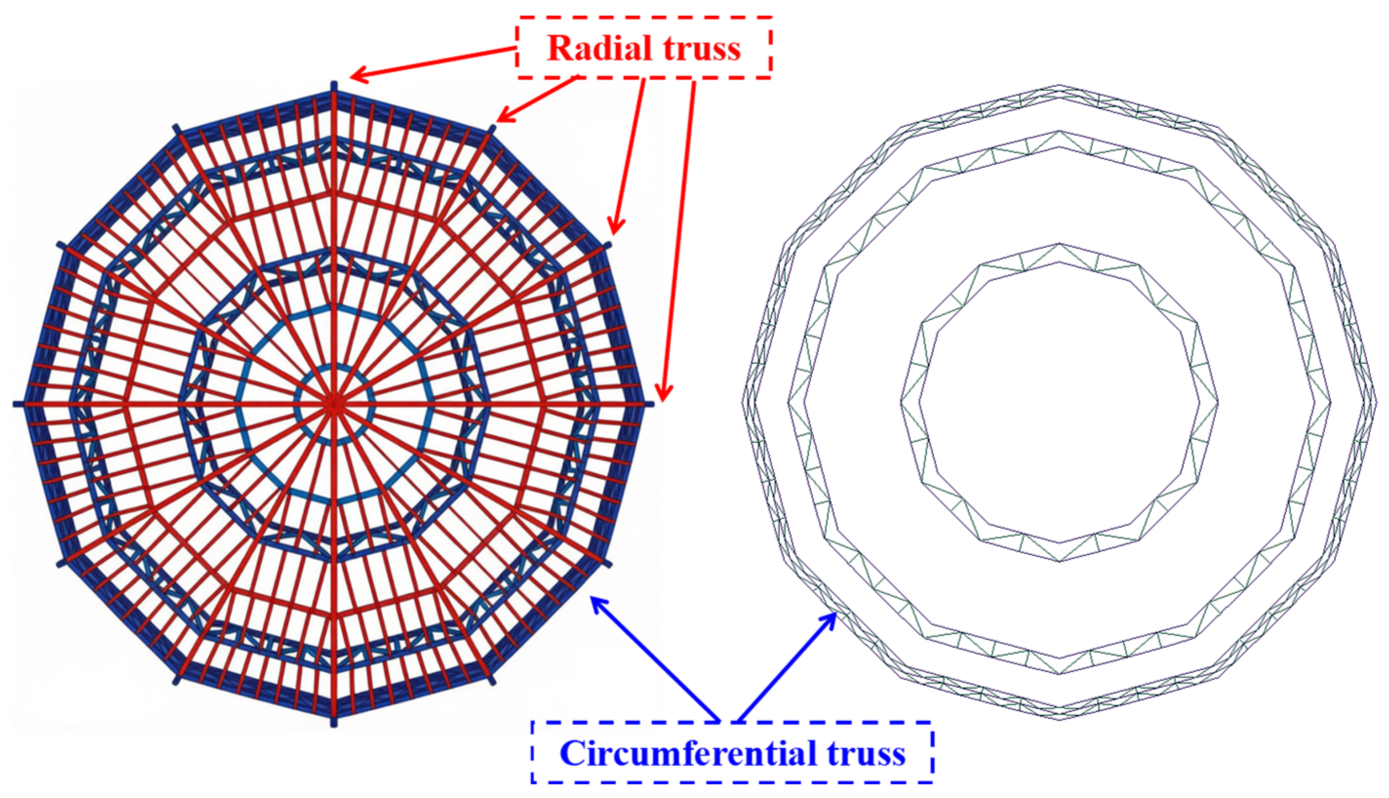
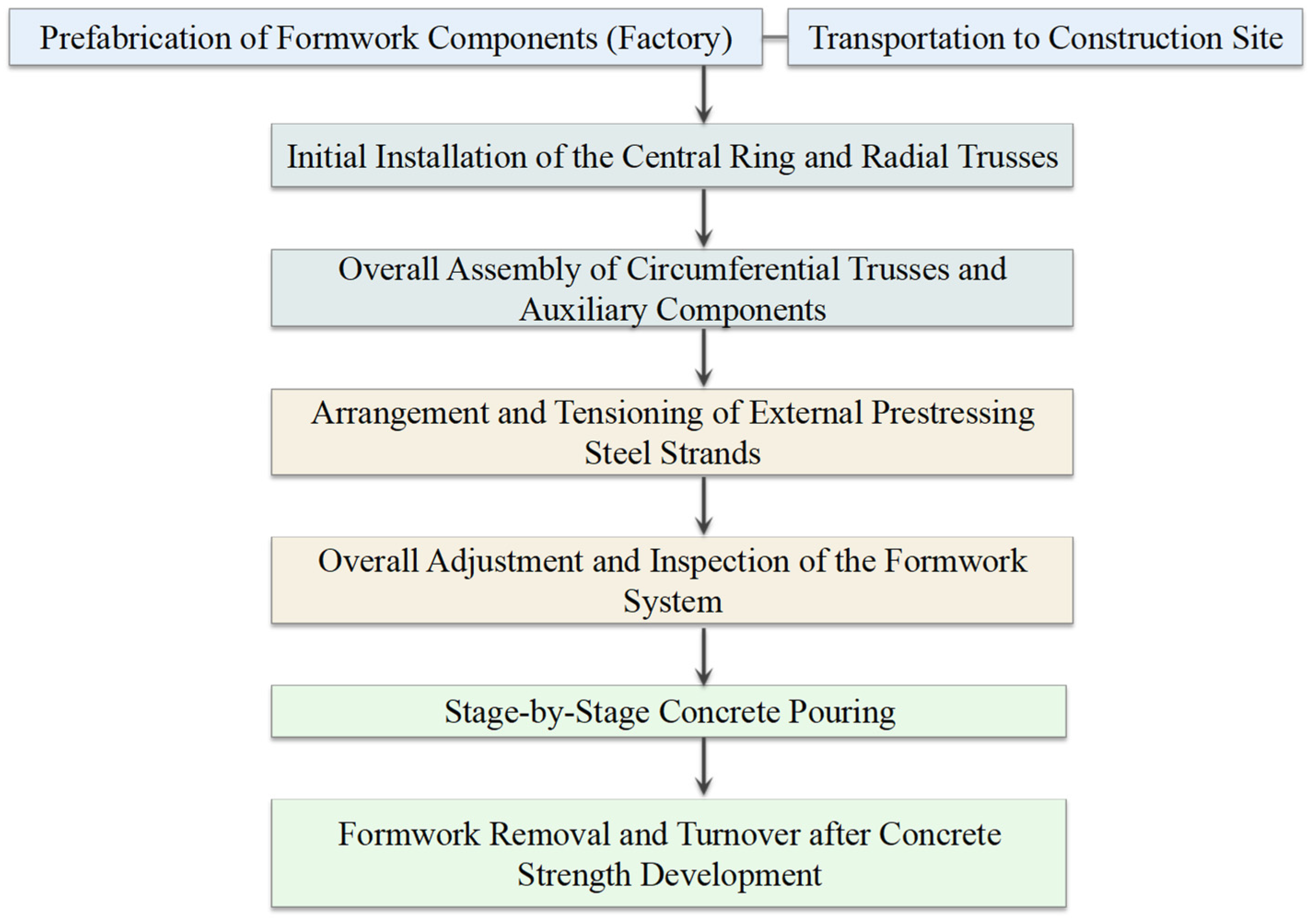
Motivated by these identified challenges, this study proposes a novel externally prestressed modular aluminum alloy formwork system for large-span concrete dome construction. The system adopts a spatial truss configuration comprising radial and circumferential members assembled entirely with bolted connections; it incorporates external prestressing via steel strands to enhance global stiffness. Finite element models are developed to simulate the construction process under staged loading and prestressing conditions, facilitating a detailed analysis of deformation characteristics and stress distributions at critical construction stages. Furthermore, comparative investigations are conducted to assess the effects of varying concrete casting schemes and prestressing levels. Ultimately, this research aims to provide theoretical support and practical guidance for the safe and efficient construction of large-span dome formwork systems.
3. Finite Element Modeling and Construction-Stage Analysis Methodology
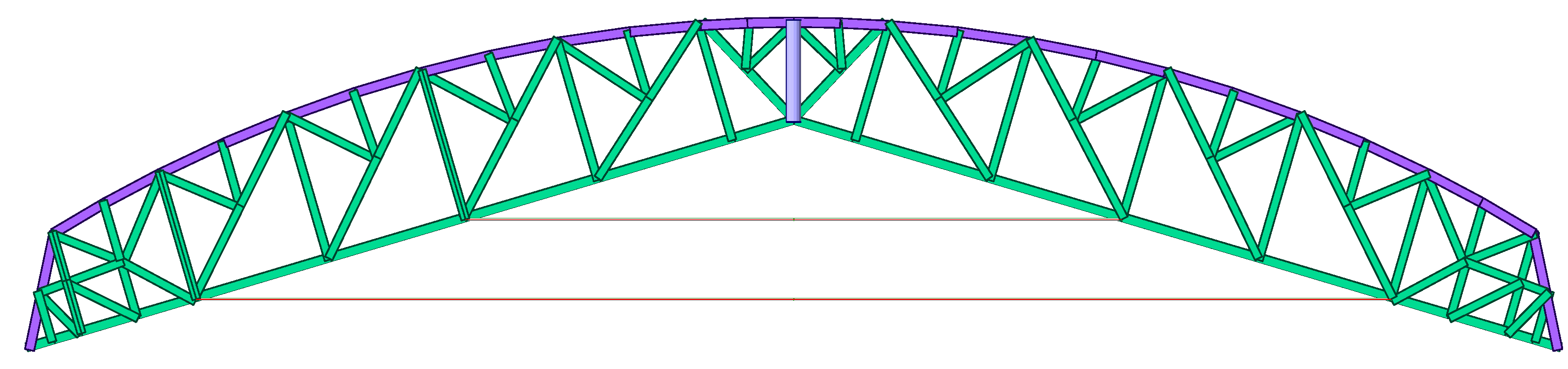
To investigate the global mechanical performance of the prestressed modular aluminum alloy dome formwork during construction, a finite element (FE) numerical approach is adopted to simulate the stress and deformation responses under various construction scenarios. Given that the proposed framework represents a typical spatial truss structure, and because this study focuses on global construction-stage responses rather than local member buckling, the modeling strategy primarily utilizes three-dimensional bar (truss) elements. The structure is consequently idealized as a spatial truss system, employing 3D truss elements for both the aluminum members and the external prestressing tendons. To reflect the primary load-transfer mechanism, all joints are idealized as perfectly pinned connections. Each physical member is represented by a single corresponding truss element to optimize computational efficiency while maintaining macroscopic accuracy.
The finite element model is developed using the commercial software package MIDAS/Gen 2020 [
30], which has proven highly robust and reliable for analyzing spatial truss structures, simulating construction sequences, and evaluating prestressed structural systems. Owing to its strong engineering applicability, this platform has been extensively utilized in prior research focusing on temporary structures and construction-phase structural analyses.
3.1. Material Properties
The primary load-bearing members of the modular framework (e.g., chords and web members) are fabricated from aluminum alloy. Because the design stress level of the structure throughout the entire construction process is strictly controlled within the elastic range, a bilinear elastoplastic constitutive model is adopted to characterize the material behavior of the 6061-T6 aluminum alloy, thereby enhancing modeling clarity. The key mechanical properties of this aluminum alloy—including its elastic modulus, Poisson’s ratio, and yield strength—are determined based on material testing and relevant design specifications, with specific values summarized in
Table 3. Furthermore, the external prestressing mechanism utilizes high-strength, low-relaxation steel strands with a nominal tensile strength of 1860 MPa. In the numerical simulation, these steel strands are modeled using a linear elastic constitutive relationship, and the prestressing effect is simulated by introducing an initial strain.
3.2. Finite Element Model Development
To simulate the stress and deformation evolution of the assembled aluminum alloy dome formwork during concrete casting, the structure is idealized as a spatial truss system. All joints are modeled as perfectly pinned connections; consequently, member behavior is assumed to be governed exclusively by axial forces, entirely neglecting joint rotational stiffness. The concrete casting loads are converted into equivalent nodal loads via a tributary load-transfer surface and subsequently distributed to the upper chord nodes.
The external prestressing is introduced via a mid-tensioning approach. In the initial analysis step, only the structural self-weight of the framework is considered. During the prestressing stage, the applied force is modeled as an equivalent external nodal load, temporarily neglecting the stiffness contribution of the steel strands. Because the tendons are configured as straight, unbonded external cables lacking curvature, frictional losses and path-dependent stress redistributions are strictly negligible. Consequently, the equivalent load method provides a highly accurate representation of the structure’s initial stress state. Upon transitioning to the construction loading stage, the steel strands and the framework act compositely; thus, the axial stiffness of the strands is activated and incorporated into the global structural stiffness matrix. Given that the maximum deflection-to-span ratio during construction is only about 1/857—ensuring a substantial stability margin—the construction-stage analysis is conducted under the small-deformation assumption. At these minimal deformation levels, second-order geometric (P-Delta) effects are deemed negligible and do not significantly alter internal force redistribution.
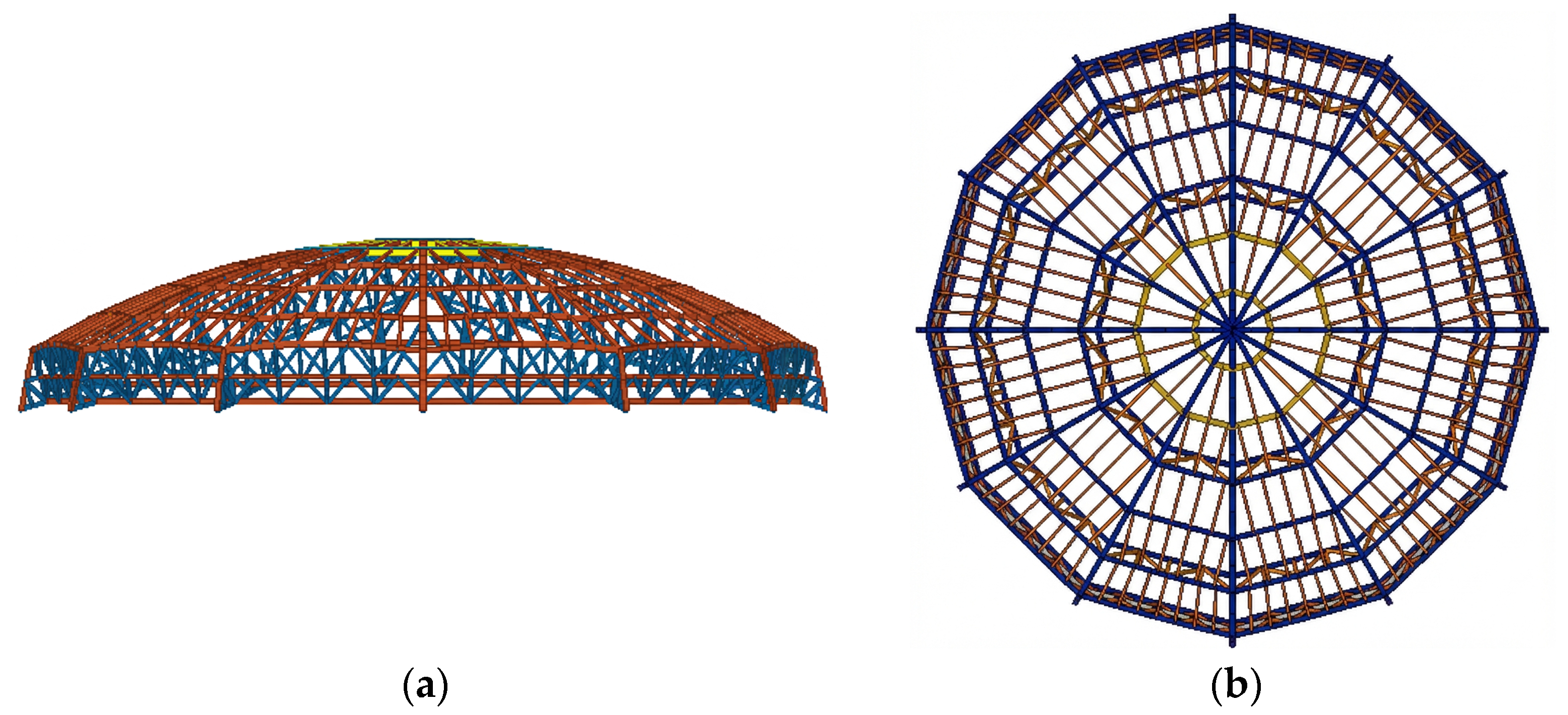
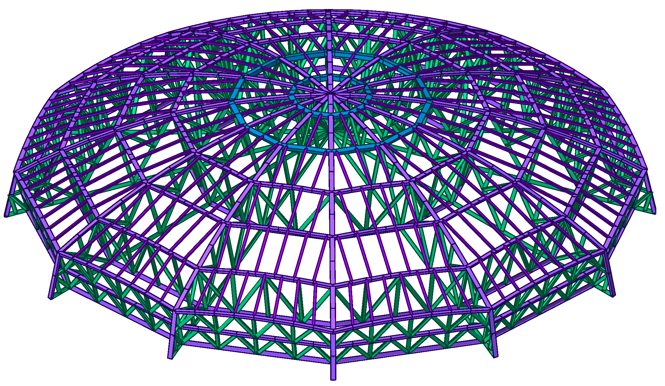
The boundary conditions of the formwork system are modeled via sliding pinned supports at the perimeter, which permit radial translational movement while releasing all rotational degrees of freedom. Conversely, the translational degrees of freedom in the tangential and vertical directions are strictly restrained to prevent uncontrolled displacements. This specific support configuration alleviates secondary internal forces induced by temperature variations and geometric incompatibilities during dome construction, thereby providing a more realistic representation of the framework’s structural behavior throughout the construction sequence. The complete finite element model is illustrated in
Figure 7. Ultimately, this boundary assumption represents a conservative modeling strategy, as it prevents the overestimation of in-plane restraint stiffness at the perimeter.
3.3. Load Definition and Construction Scenarios
3.3.1. Load Definition
During the construction stage of the dome, the aluminum alloy formwork system is primarily subjected to dead loads and live loads. The dead loads include the self-weight of the formwork system, the self-weight of the reinforced concrete dome, the weight of construction formwork, as well as the weights of purlins and timber planks. The live loads are mainly attributed to construction personnel, construction equipment and material stacking, concrete vibration operations, and additional dynamic effects generated during construction.
In accordance with the provisions of the Technical Code for Safety of Formwork in Construction [
31], the standard value of the formwork self-weight is specified as 0.5 kN/m
2. Based on the Load Code for the Design of Building Structures (GB 50009-2012) [
32], the standard unit weight of reinforced concrete is taken as 25 kN/m
3. Given the structural characteristics of the earth-covered tank dome, the concrete casting thickness varies linearly from 500 mm at the perimeter to 200 mm at the apex. Accordingly, within the finite element model, the wet concrete load is represented as a distributed area load that varies linearly from the apex to the perimeter. Specifically, the concrete load is calculated as 12.5 kN/m
2 (25 × 0.5) at the perimeter and 5.0 kN/m
2 (25 × 0.2) at the apex. The live loads acting on the formwork encompass the weight of construction personnel, equipment, material stacking, concrete vibration operations, and associated dynamic effects. Pursuant to Ref. [
32], for a truss-type framework, the standard value of the construction live load is established at 2.0 kN/m
2.
The live loads acting on the construction formwork include loads from construction personnel, construction tools and material stacking, concrete vibration operations, and dynamic effects during construction. According to Ref. [
32], when a truss-type formwork system is adopted, the standard value of the construction live load is taken as 2.0 kN/m
2. The specific load application procedure is conducted as follows:
First, virtual tributary surfaces are established to facilitate accurate load distribution.
Second, surface loads are applied to these virtual surfaces along the global Z-axis utilizing the software’s pressure load function.
Third, the software automatically converts these surface pressures into equivalent nodal loads, distributing them precisely to the upper chord nodes.
Last, load combinations are formulated, and the computational analysis of the framework is performed under various operational load cases.
3.3.2. Definition of Construction Scenarios
Because the construction framework investigated in this study is classified as a temporary structure, seismic actions are excluded from the analysis. This aligns with standard design provisions, which generally exempt temporary structures from seismic design requirements. Regarding load combinations, the temporary framework strictly adheres to the provisions stipulated in the General Code for Engineering Structures (GB 55001-2021) [
33]. Consequently, the partial load factors are specified as 1.3 for dead loads and 1.5 for live loads.
To account for two typical concrete casting schemes for dome construction—namely, layered casting and circumferential casting—four representative construction scenarios are defined to evaluate the structural response of the framework throughout the construction process. The load combinations acting on the framework across various construction stages are detailed in
Table 4. Notably, aluminum alloys exhibit a relatively high coefficient of thermal expansion (approximately 2.3 × 10
−5/°C). In outdoor environments, significant temperature variations can induce axial deformations in structural members and potentially alter prestress levels within cable-supported systems. However, temperature effects are not explicitly incorporated into the current numerical analysis. This exclusion is justified by the relatively short construction duration, ensuring that prestress application and concrete casting are completed within tightly controlled operational timeframes. Furthermore, as previously established, the radially sliding boundary configuration permits limited in-plane displacement, which naturally alleviates restraint-induced thermal stresses. Consequently, thermal actions are not expected to govern the structural response during this temporary construction phase.
The current structural analysis primarily focuses on the most unfavorable vertical load combinations under gravity-dominated construction scenarios. Wind loading is not explicitly considered, as the framework is a temporary structure with a highly limited duration of wind exposure. Furthermore, on-site operations are strictly governed by wind-speed control regulations, and temporary safety measures—such as guy cables and lateral restraint systems—are deployed to guarantee lateral stability. However, during intermediate construction stages in practice, the structure typically exhibits incomplete geometry, reduced global stiffness, and non-uniform load paths. These factors render the framework potentially more vulnerable to wind-induced pressures, suction effects, and aeroelastic instabilities that cannot be fully captured by a purely gravity-dominated analysis. Existing literature demonstrates that wind actions can induce significant out-of-plane displacements and second-order (P-Δ) effects in spatial dome structures [
34], potentially triggering complex aeroelastic responses due to unfavorable flow-structure interactions [
35]. Moreover, wind-induced vulnerabilities and overall aerodynamic characteristics play a critical role in the ultimate safety of various dome-type structures [
36,
37]. Therefore, future research should explicitly investigate wind actions and aeroelastic effects within a geometrically nonlinear analysis framework. This will account for potential stiffness degradation and ensure the adequate safety of the framework under adverse environmental conditions.
3.4. Determination of Prestressing Force
3.4.1. Preliminary Determination of the Prestressing Level
According to existing design provisions [
38], the control stress of prestressing tendons, σ_con, in prestressed concrete structures is typically taken within the range of 0.4f
ptk–0.75f
ptk. However, for prestressed aluminum alloy structures, a unified standard for the prestressing control stress has not yet been clearly defined, owing to pronounced differences in internal force transfer mechanisms and deformation characteristics associated with different truss configurations.
In prestressed aluminum alloy structural systems, steel strands are generally arranged externally. Compared with internal prestressing systems in prestressed concrete structures, externally applied prestressing systems usually exhibit relatively limited durability and safety redundancy. Therefore, the prestressing control stress should be conservatively limited within the commonly adopted range for prestressed concrete structures.
Based on the above considerations, the prestressing control stress of the steel strands in this study is preliminarily defined within the range of 0.4fptk–0.75fptk, subject to the satisfaction of the following conditions.
3.4.2. Calculation of Prestress Losses
According to the relevant design provisions [
39], the prestress losses of low-relaxation steel strands mainly include anchorage slip loss and stress relaxation loss. These two types of prestress losses are considered in the present study.
For low-relaxation prestressing steel strands, the anchorage slip loss is calculated using Equation (1):
where
is the effective anchorage slip length (taken as 1 mm for threaded anchorage and 2 mm for wedge anchorage),
is the cross-sectional area of the steel strand,
is the elastic modulus of the steel strand, and
is the effective length of the prestressing tendon.
In addition, the stress relaxation loss of the prestressing steel strands is calculated according to the following expressions:
where
is the prestressing control stress and
is the characteristic tensile strength of the prestressing steel strand.
Considering that the prestressing system investigated in this study is externally applied and serves a temporary construction purpose, other long-term prestress losses, such as creep and shrinkage of concrete, are not considered. The adopted prestress loss calculation approach is therefore consistent with the structural characteristics and service conditions of the proposed formwork system.
3.4.3. Numerical Investigation of the Applied Prestressing Level
To identify an appropriate prestressing level for the steel strands, a parametric finite element analysis is performed under the most unfavorable construction scenario. Three representative prestressing control stress levels, namely 0.3fptk, 0.5fptk, and 0.7fptk, are applied to the assembled dome formwork system.
The effects of different prestressing levels on the structural performance are systematically evaluated by comparing the maximum vertical displacement, the maximum tensile stress of members, and the radial displacement of supports. These response indices are selected to comprehensively assess the deformation control efficiency, internal force distribution, and boundary behavior of the formwork system.
- (1)
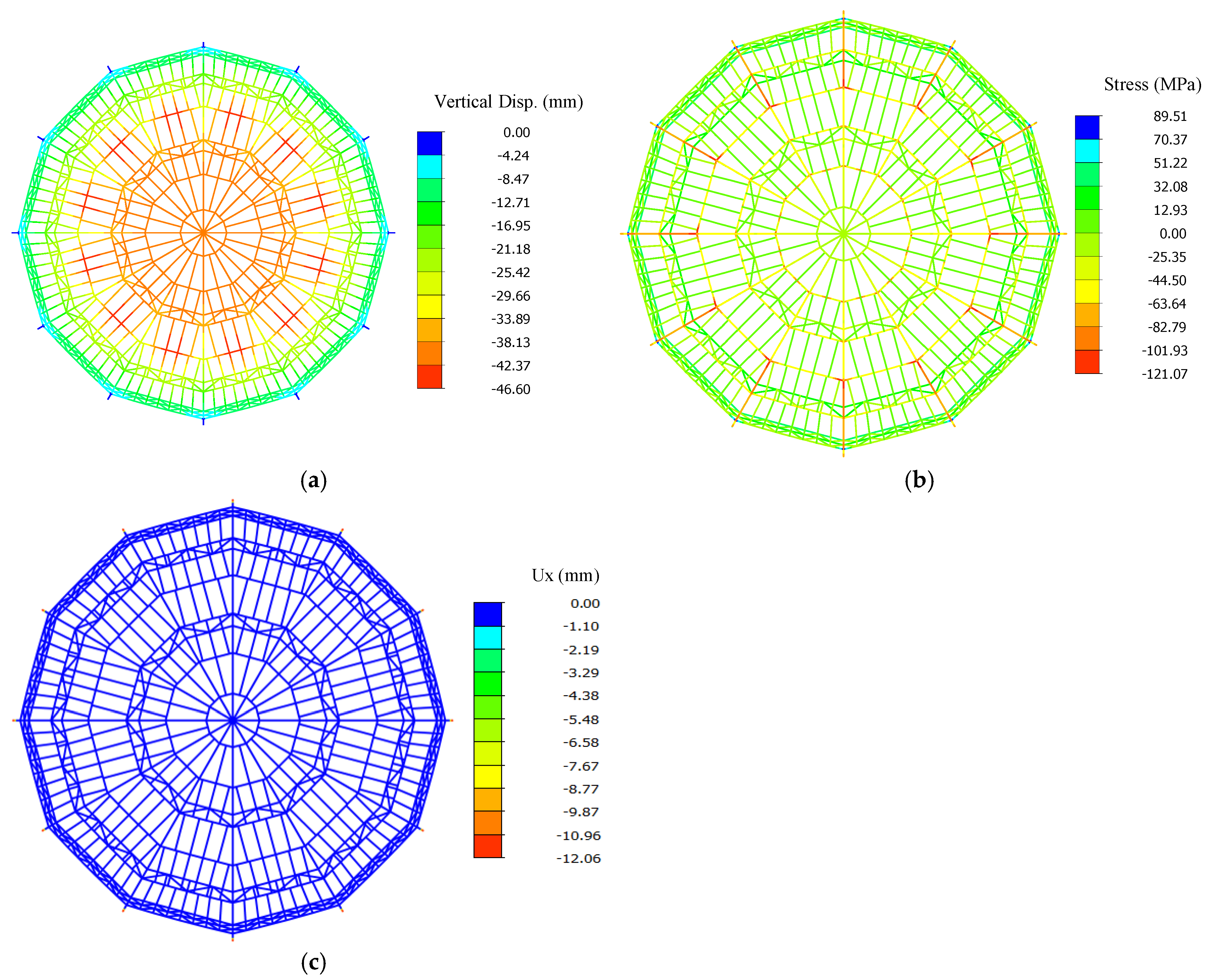
Finite element analysis results under a prestressing level of 0.3f
ptk (see
Figure 8)
Under a prestressing level of 0.3fptk, the displacement field and member internal force distribution of the construction formwork exhibit clear centrosymmetric characteristics. The maximum vertical displacement reaches 46.60 mm, while the maximum tensile stress of members is 89.51 MPa. In addition, the radial displacement of the supports in the X direction attains a maximum value of 12.06 mm.
The vertical displacement increases gradually from the supports toward the central ring and then decreases, reaching its peak at the mid-span region. In contrast, the tensile stress in members increases progressively from the central ring toward the supports, with the maximum value occurring in the web members near the support region.
- (2)
Finite element analysis results and discussion under a prestressing level of 0.5fptk (see
Figure 9)
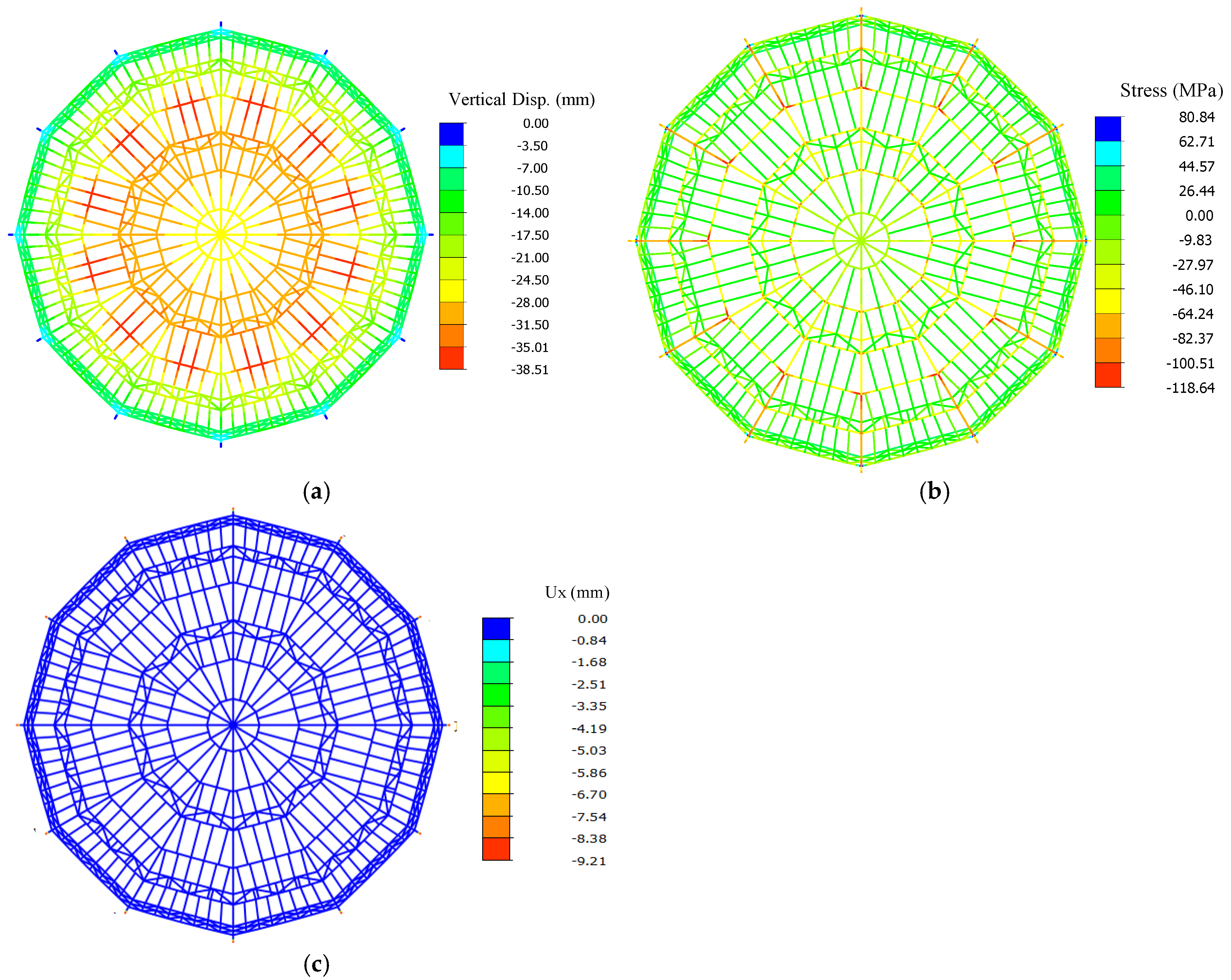
Under a prestressing level of 0.5fptk, the maximum vertical displacement of the construction formwork is reduced to 38.51 mm, representing an approximately 18% decrease compared with the 0.3fptk case. Meanwhile, the maximum tensile stress of members decreases to 80.84 MPa, corresponding to a reduction of about 10%. The radial displacement of the supports in the X direction is further reduced to 9.21 mm, exhibiting a decrease of approximately 24%.
These results indicate that increasing the prestressing level of the steel strands leads to a consistent reduction in vertical displacement, member tensile stress, and radial support displacement of the construction formwork system.
- (3)
Finite element analysis results and discussion under a prestressing level of 0.7f
ptk (see
Figure 10)
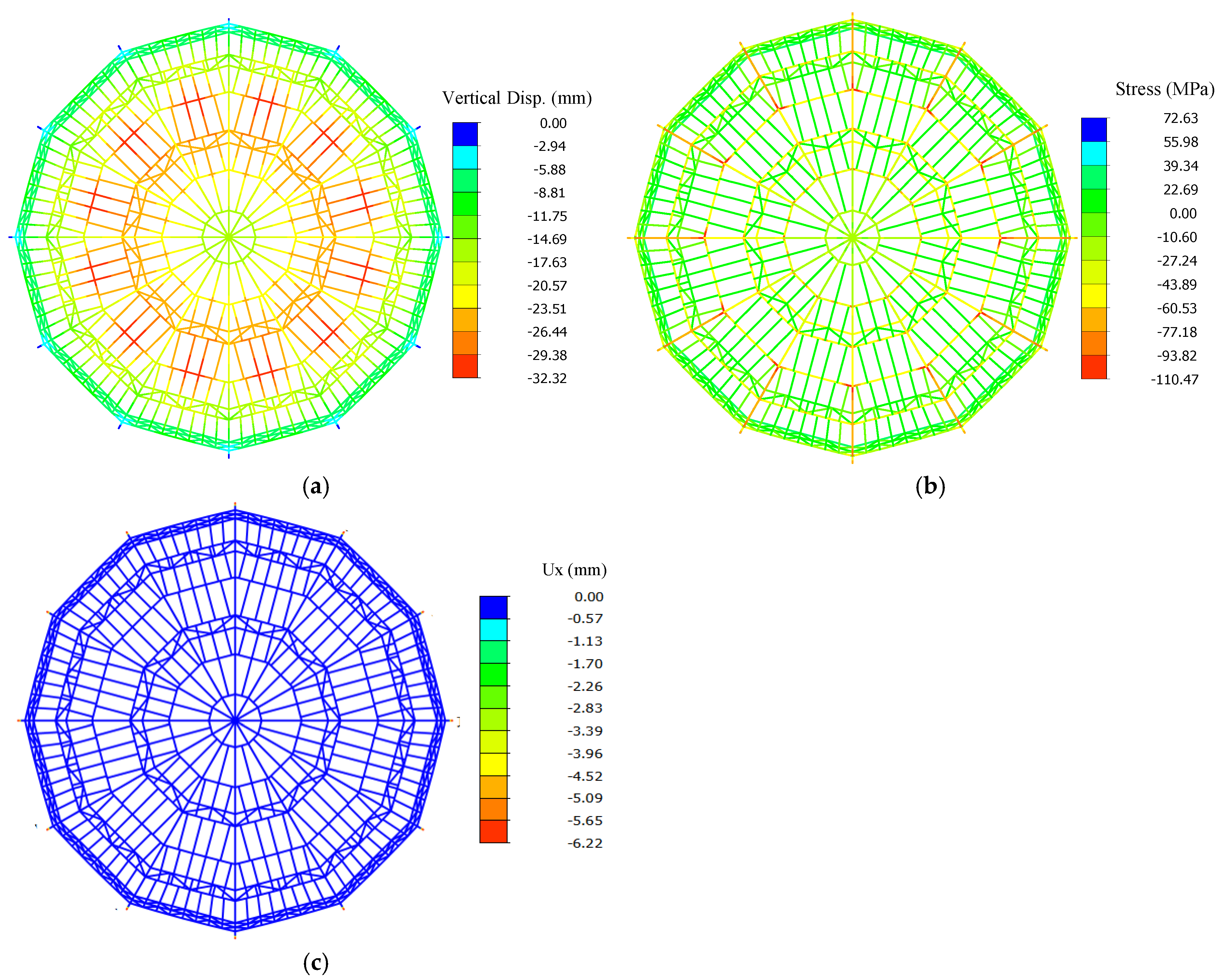
Under a prestressing level of 0.7fptk, further reductions in vertical displacement, member tensile stress, and radial support displacement in the X direction are observed compared with the lower prestressing levels. The maximum vertical displacement decreases to 32.32 mm, the maximum tensile stress of members reduces to 72.63 MPa, and the radial displacement of the supports in the X direction decreases to 6.22 mm.
The numerical results obtained under the three prestressing levels are summarized in
Table 5.
The results indicate that, with increasing prestressing level of the steel strands, the maximum vertical displacement and the radial displacement of the supports decrease significantly, while the maximum tensile stress of members is reduced simultaneously. All three response indices exhibit an approximately linear variation trend with respect to the prestressing level.
By comprehensively evaluating the numerical analysis results alongside practical construction feasibility, this study recommends a control prestress level of $0.5fptk (930 MPa). This recommendation is contingent upon the premise that stresses within both the framework members and the prestressing steel strands remain strictly within their respective design limits. After accounting for anticipated prestress losses, the effective prestressing levels are established at 914.8 MPa for the large-diameter strands and 902.2 MPa for the small-diameter strands. Furthermore, within the investigated range, structural displacement varies almost linearly in response to the applied tension level. Around the recommended prestress level of $0.5fptk, a ±5% variation in the initial cable tension is estimated to induce a mere ±1 mm fluctuation in the maximum vertical displacement. This negligible deflection suggests that the global dome geometry is not highly sensitive to standard field tensioning tolerances. Nevertheless, controlled tensioning procedures and rigorous on-site verification remain highly recommended to guarantee absolute construction accuracy.
4. Overall Structural Performance Analysis of the Construction Formwork
Based on the finite element modeling approach and construction-stage scenarios described above, the global mechanical performance of the prestressed modular aluminum alloy dome construction formwork is systematically investigated under different construction stages. The analysis focuses on the structural response characteristics during concrete casting, with particular attention paid to deformation behavior and its variation under different construction schemes.
4.1. Deformation Analysis Under Different Concrete Casting Schemes
Structural deformation during the construction phase serves as a critical indicator for evaluating the global stiffness and load-bearing performance of the temporary framework.
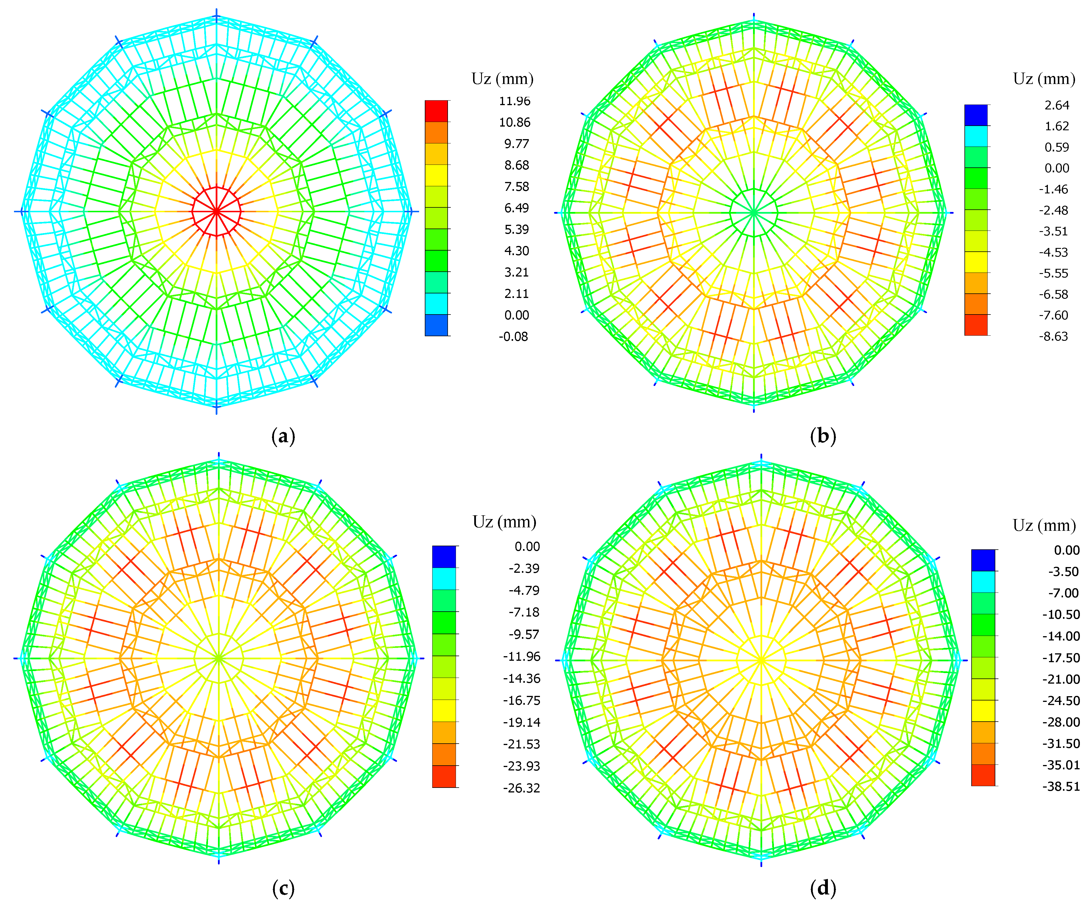
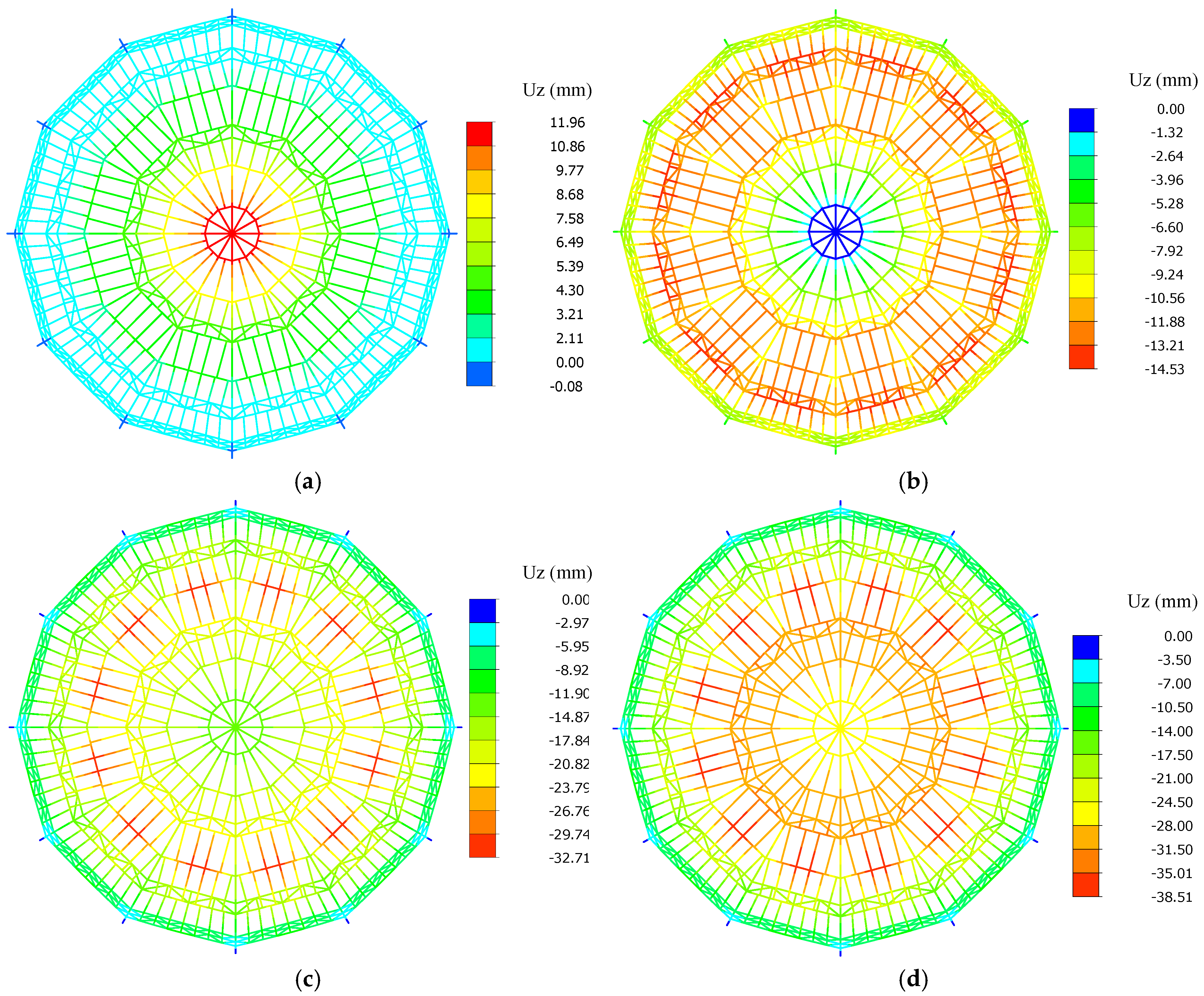
Table 6 details the maximum vertical displacements of the dome framework across four representative construction scenarios, comparing two distinct concrete casting schemes: layered casting and circumferential casting.
Figure 11 and
Figure 12 illustrate the corresponding finite element deformation contours for these two casting methodologies, respectively. Notably, all calculated maximum displacements strictly satisfy the allowable deflection limit of 1/250 of the span, as mandated by the Technical Specification for Space Frame Structures [
40]. To maintain this structural integrity in practice, strict quality control measures must be implemented during actual construction. These measures will ensure continuous and symmetric concrete placement, actively mitigating the risk of irregular or asymmetric casting sequences that could induce uneven load distributions.
Based on the finite element results obtained from MIDAS/Gen, the vertical displacement distributions of the dome construction formwork exhibit generally consistent patterns under the two construction schemes and four representative construction scenarios. The vertical displacement increases gradually from the central ring toward the supports and then decreases, reaching its maximum near the mid-span region of the truss, while the displacement at the supports remains minimal due to boundary constraints.
As indicated in
Table 6, although the overall displacement distribution patterns are similar for different concrete casting schemes, noticeable differences exist in the maximum vertical displacement. Specifically, the layered casting scheme results in relatively smaller maximum vertical displacements, whereas slightly larger displacements are observed under the circumferential casting scheme.
4.2. Stress Distribution Characteristics of Structural Members
The stress distributions of the primary members of the construction formwork during the construction stage are summarized in
Table 7 and
Table 8. The results indicate that different types of members exhibit distinct stress characteristics during construction. Specifically, the lower chords in the radial trusses are predominantly subjected to tensile forces, whereas the upper chords mainly experience axial compression. In contrast, the web members exhibit alternating tensile and compressive stress states at different construction stages.
These stress distribution characteristics are consistent with the load-transfer mechanism of spatial truss systems, reflecting the different structural roles played by various members during the construction process.
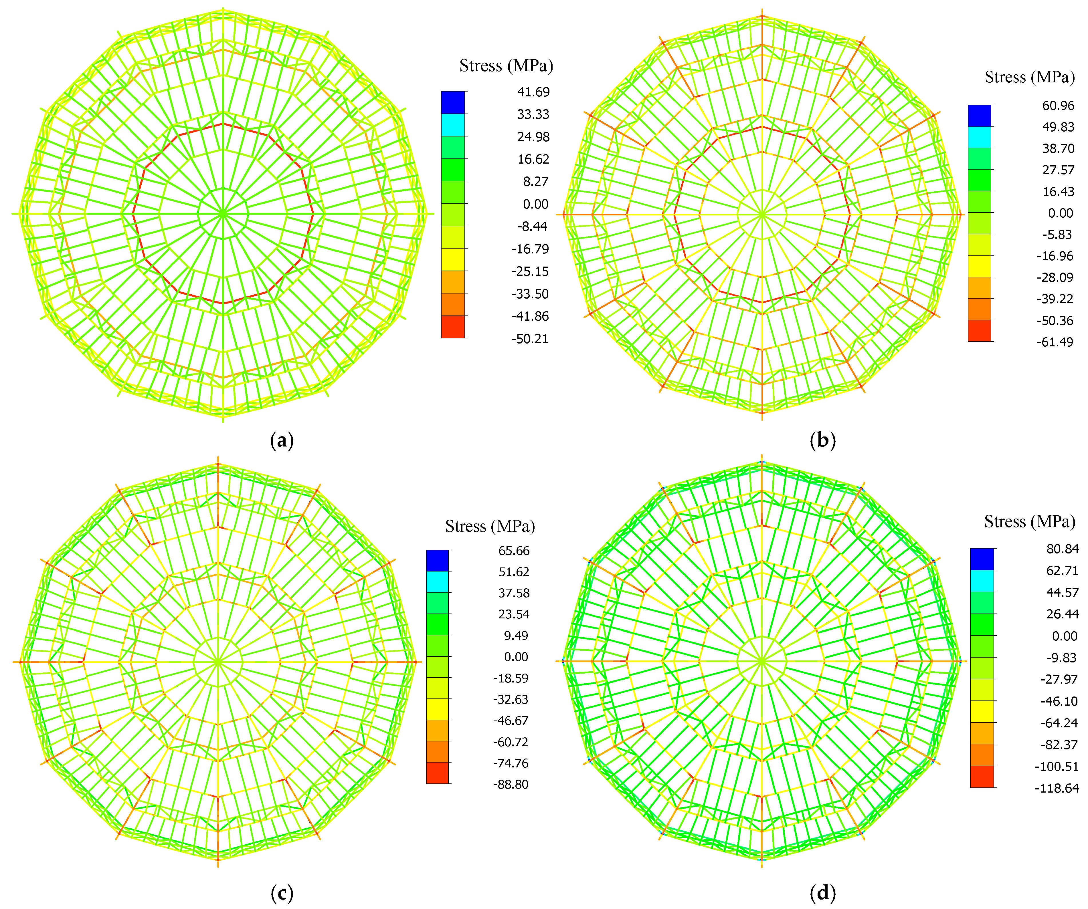
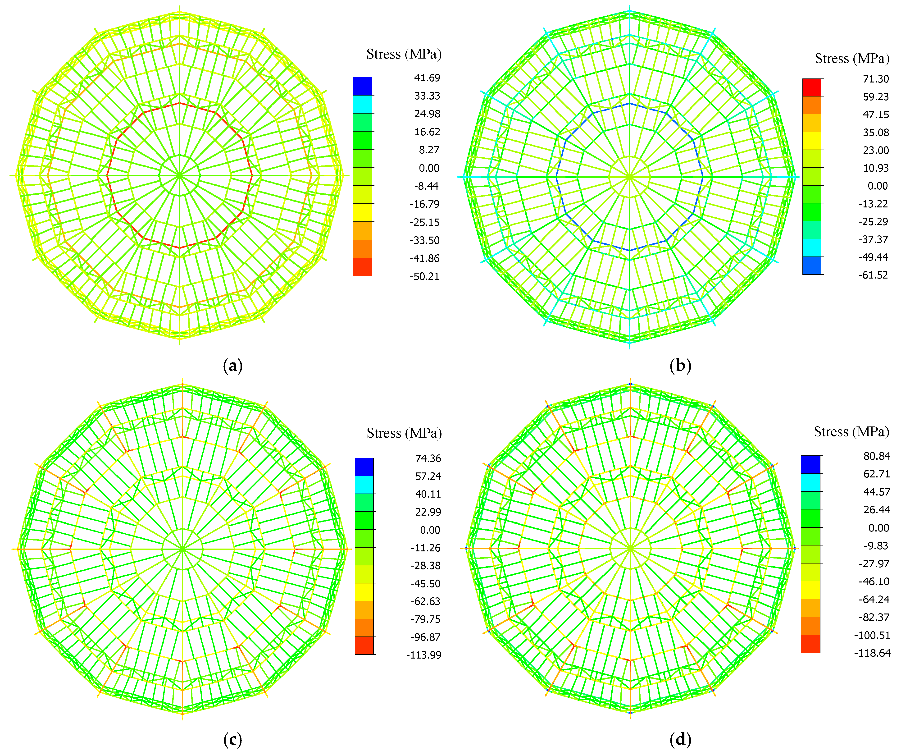
Under the fully cast concrete condition, the maximum stresses of various structural members are primarily concentrated in the mid-span region of the radial trusses, which generally coincides with the locations of maximum global deformation. The stress contours of structural members under different casting schemes are presented in
Figure 13 and
Figure 14, respectively, where the lower chords of the radial trusses exhibit relatively high tensile stress levels and act as one of the primary load-bearing components during construction. As the construction process progresses, the stresses in the structural members show an overall increasing trend, while the stress growth rates differ among member types. This behavior reflects the internal force redistribution process inherent in the spatial truss system during construction.
4.3. Stability Analysis of the Construction Formwork
The stability of formwork members is one of the key factors governing the structural safety during construction. The stress ratio of compression members is an important indicator for evaluating the potential instability of structural members. According to relevant design provisions, the stability stress ratio of axially compressed aluminum alloy members can be calculated as follows:
where
is the axial compressive force acting on the member (
N); φ is the stability coefficient of the axially compressed member, taken as the smaller value corresponding to the two principal axes;
is the cross-sectional area of the member (mm
2); and fff is the design compressive strength of the aluminum alloy material (N/mm
2). Furthermore, the width-to-thickness ratios of all aluminum members strictly satisfy the non-slender section requirements stipulated in the relevant structural design provisions, ensuring that local plate buckling does not govern the design.
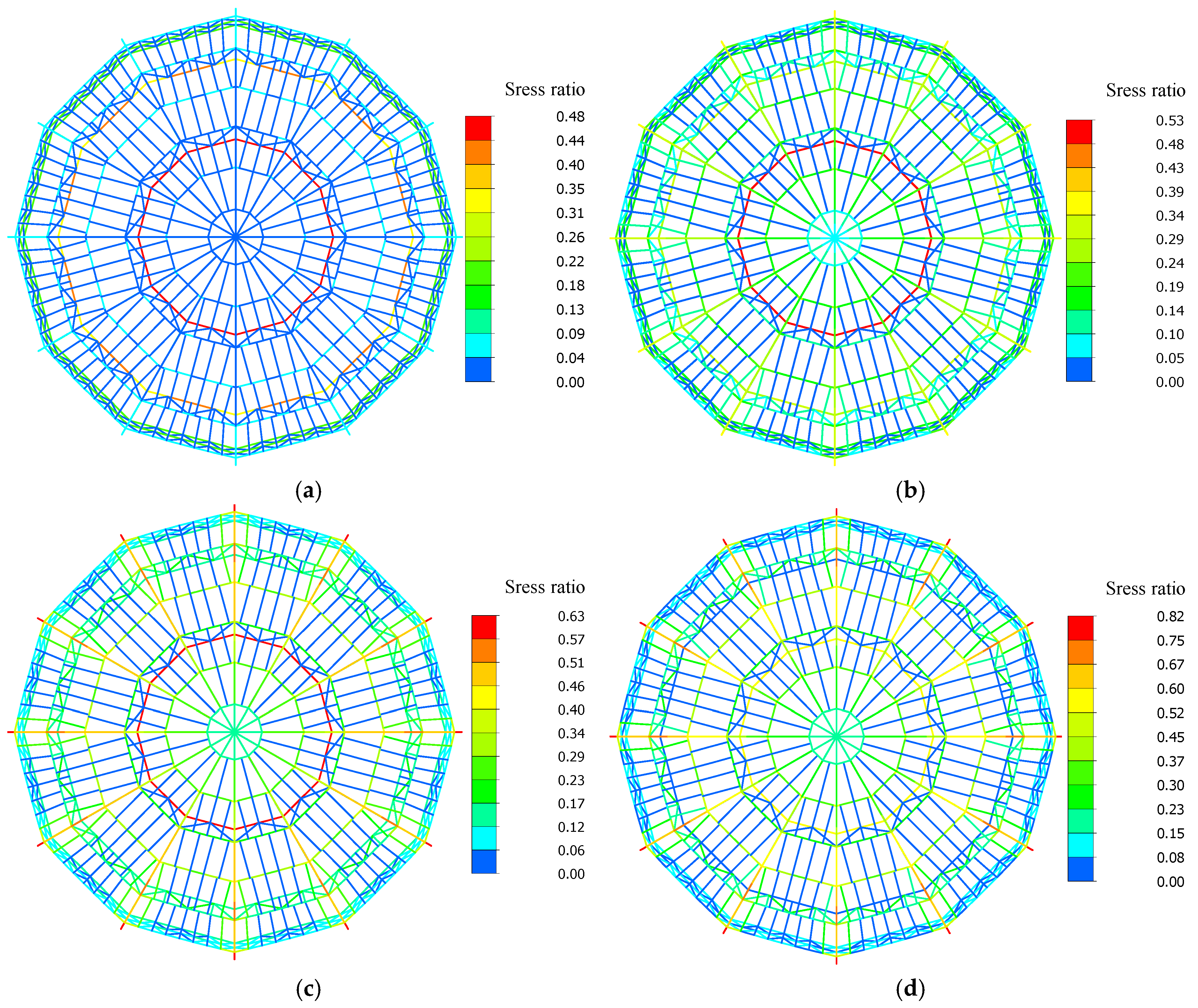
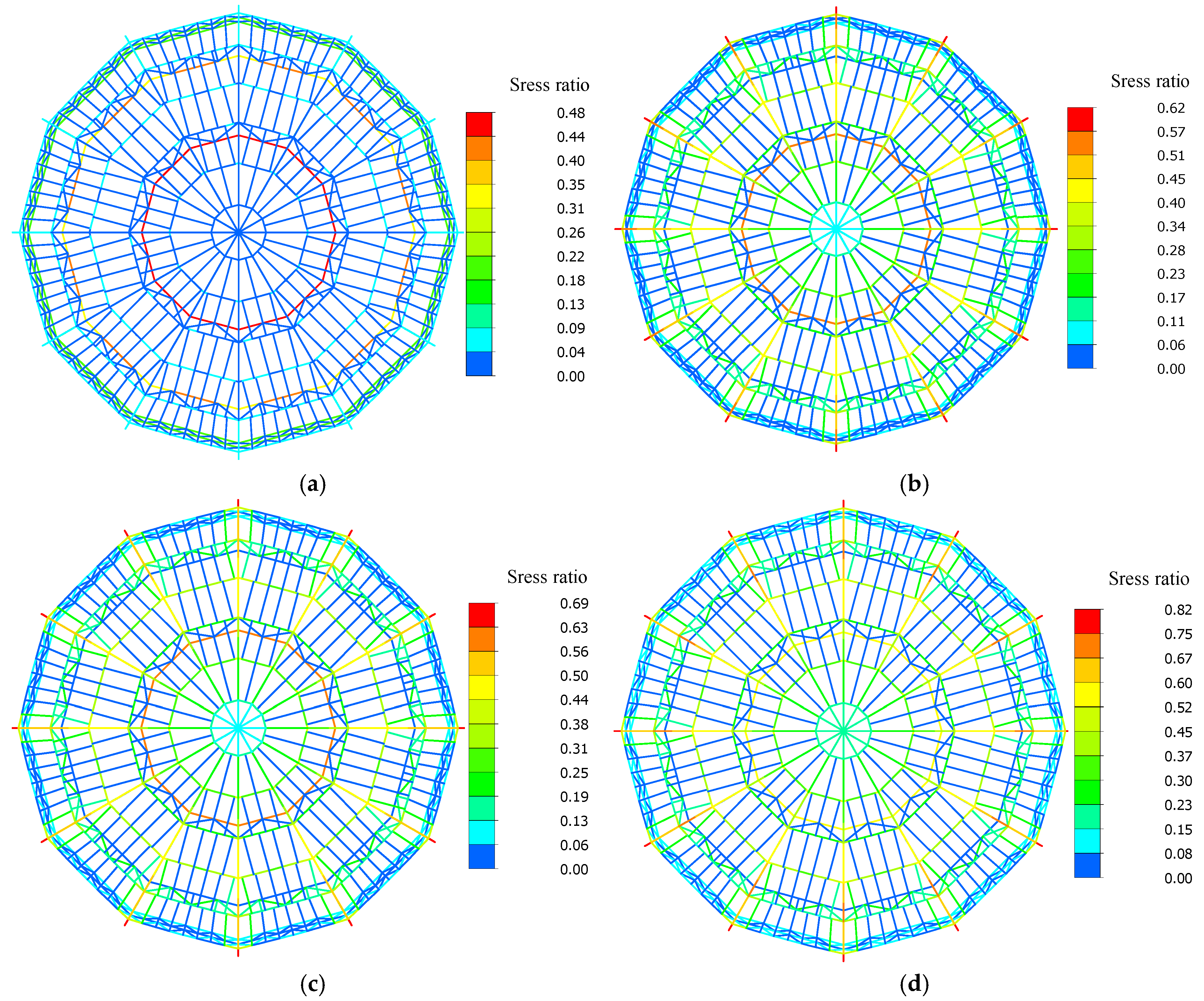
Based on finite element analyses conducted using MIDAS/Gen, the stability stress ratios of compression members in the construction formwork are evaluated under four representative construction scenarios for both the layered casting and circumferential casting schemes. The contour distributions of the stability stress ratios are presented in
Figure 15 and
Figure 16. It should be noted that the elastic modulus of aluminum alloy (E = 71,542 Mpa) is significantly lower than that of structural steel. In the present finite element model, the flexural rigidity (EI) of each compression member directly incorporates this reduced elastic modulus. Therefore, the calculated buckling eigenvalues inherently reflect the influence of aluminum’s lower stiffness.
Under Scenario 1, the maximum stability stress ratio of the compression members in the construction formwork is the smallest, with a value of 0.48. In contrast, under Scenario 4, the maximum stability stress ratio reaches 0.82, which is the largest among all scenarios and still satisfies the stability control requirement of 0.82 < 0.9. A comparison between the two concrete casting schemes indicates that, under Scenarios 2 and 3, the stability stress ratios of members in the layered casting scheme are consistently lower than those in the circumferential casting scheme. This observation demonstrates that the layered casting scheme is more favorable for maintaining the structural stability of the formwork during construction.
4.4. Linear Buckling Analysis
Linear buckling analysis is generally applicable to idealized structural systems, in which initial geometric imperfections as well as material and geometric nonlinearities are not taken into account. This method is commonly used to evaluate the elastic stability characteristics of structures. In this study, linear buckling analysis of the dome construction formwork is conducted using the finite element software MIDAS/Gen, and the resulting buckling eigenvalues are expressed in the form of load multipliers.
Under the most unfavorable construction-stage load combination, i.e., 1.3 times the dead load plus 1.5 times the live load, linear buckling analysis is performed for the assembled aluminum alloy dome formwork with a diameter of 33 m. The first six buckling mode eigenvalues are summarized in
Table 9. In the buckling analysis model, the dead load is defined as a constant load, while the live load is defined as a variable load, so as to ensure the rationality and code consistency of the calculated buckling eigenvalues.
As indicated in
Table 9, under the most unfavorable load combination (1.3 times the dead load plus 1.5 times the live load), the first linear buckling eigenvalue of the assembled aluminum alloy construction formwork is 23.04, and the eigenvalues of the first six buckling modes are very close to each other. This result suggests that multiple competing instability paths may exist near the critical buckling state, and the buckling response is sensitive to the stiffness distribution of local members.
Meanwhile, no typical global flexural–torsional buckling or overall lateral sway instability mode is observed. All buckling eigenvalues exceed 23, indicating that the critical buckling load of the structure is significantly higher than the applied design load level under the considered load combination. Therefore, the formwork system retains a substantial margin of load-carrying capacity and stability, and global buckling is not a governing failure mode during the construction stage.
4.5. Nonlinear Buckling Analysis
In the nonlinear buckling analysis, the displacement field of the first buckling mode obtained from the linear buckling analysis is adopted as the shape of the initial geometric imperfection. The imperfection shape is scaled according to a prescribed imperfection amplitude and introduced into the numerical model as the initial configuration. Subsequently, the structural response from the elastic stage to the buckling and post-buckling stages is traced within an incremental–iterative solution framework, enabling the determination of the ultimate load-carrying capacity of the construction formwork.
According to the Technical specification for space frame structures [
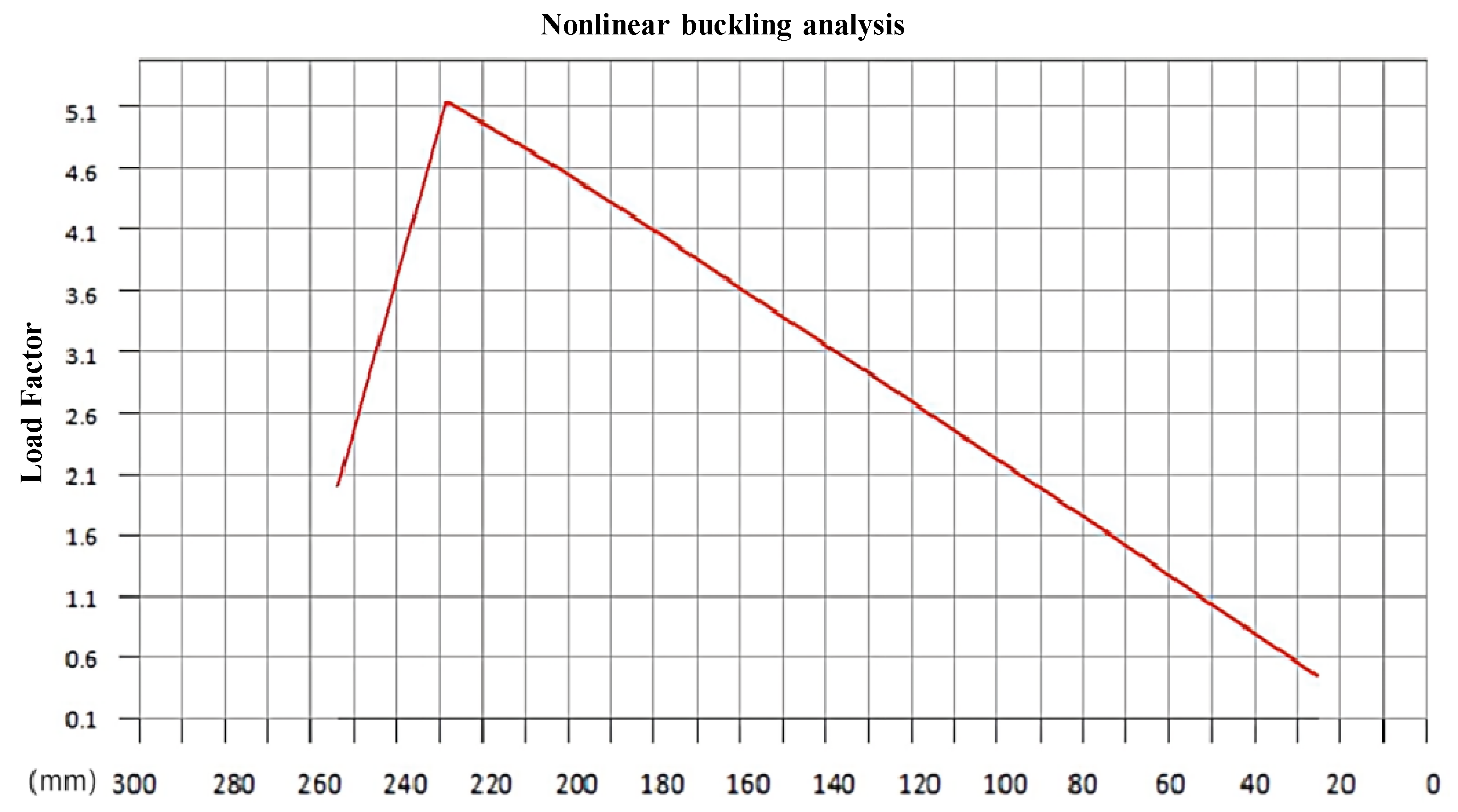
40], the maximum initial geometric imperfection is taken as 1/300 of the span of the construction formwork. Based on the above imperfection modeling strategy, nonlinear buckling analysis is performed, and the resulting load factor–displacement curve is presented in
Figure 17.
After introducing an initial geometric imperfection equivalent to 1/300 of the span of the construction formwork, the nonlinear buckling analysis indicates that the load factor exhibits pronounced nonlinear evolution with increasing control displacement. The load factor reaches a peak value of 5.1 and then gradually decreases, corresponding to a maximum displacement of approximately 228 mm at the control node.
Incorporating the unfavorable effects of initial geometric imperfections, the critical load factor of the dome construction framework is determined to be K = 5.1. This comfortably satisfies the code-specified stability safety requirement of
$K > 4.2
$. This result demonstrates that, even under the most unfavorable construction-stage loading conditions, the framework retains a robust margin of stability and substantial load-carrying capacity. Furthermore, although aluminum alloys entail a higher initial material cost compared to conventional scaffolding systems, existing lifecycle cost research [
41] demonstrates that aluminum framework systems exhibit significant long-term economic advantages. These benefits stem from a high reuse frequency, reduced labor demands, shortened construction durations, and lower maintenance requirements. Consequently, the proposed prestressed modular aluminum dome framework is anticipated to achieve highly favorable amortized lifecycle cost performance across large-span dome construction projects.