Article

Thermal Stress Evolution and Microstructural Development in Simulated Lunar Regolith During Microwave Sintering and Cooling


1
School of Materials Science and Engineering, Hebei University of Technology, Tianjin 300401, China
2
Hebei Key Laboratory of Scale-Span Intelligent Equipment Technology, School of Mechanical Engineering, Hebei University of Technology, Tianjin 300401, China
3
Beijing Institute of Spacecraft Environment Engineering, Beijing 100094, China
*
Author to whom correspondence should be addressed.
Coatings 2026, 16(2), 222; https://doi.org/10.3390/coatings16020222
Submission received: 29 December 2025 / Revised: 4 February 2026 / Accepted: 6 February 2026 / Published: 9 February 2026

Abstract

Microwave sintering technology is widely regarded as one of the most promising construction techniques for in situ resource utilization in lunar bases due to its high energy efficiency and unique heating mechanism. However, the extremely low-temperature environment on the lunar surface creates a transient temperature gradient of over a thousand degrees Celsius between the sintered body’s surface and its interior. This temperature difference induces significant thermal stress during the cooling process, leading to macroscopic surface cracks and even structural failure, which severely limits the engineering feasibility of this technology. To evaluate the surface integrity of lunar in situ sintered bodies and determine the safe processing window for microwave sintering, this study develops a multiphysics computational model that couples electromagnetic, thermal, and stress fields. The results show that when the cooling rate is below 15 °C/min, the surface stress remains below the material’s tensile strength threshold, effectively preventing crack formation. However, at a cooling rate of 16 °C/min, the surface stress exceeds this threshold, leading to crack initiation. Further analysis reveals that the cooling rate significantly affects the microstructure, with slow cooling maintaining a dense structure, while fast cooling promotes the formation of microcracks, particularly in regions with low Si/Al content. This study provides a reference for the microwave sintering process of lunar regolith and proposes a strategy of controlling the cooling rate below 15 °C/min.

1. Introduction

The Moon serves as an important forward base for deep-space exploration, rich in rare earth elements and water resources, giving it high strategic and economic value [1,2]. Due to the prohibitively high cost of transporting construction materials from Earth, utilizing in situ resources to build energy, transportation, and habitation infrastructure is crucial for sustainable exploration [3,4,5]. Therefore, in situ resource utilization (ISRU) is essential, particularly using lunar regolith as feedstock to fabricate structural components [6,7]. Sintering is considered one of the most promising ISRU techniques for early lunar base construction, especially because it does not require binders from Earth [8].
Given the scarcity of authentic lunar regolith, terrestrial regolith simulants are commonly employed in such studies [9]. Researchers have evaluated multiple sintering methods to consolidate these simulants [10]. Pressureless sintering (PLS) can produce consolidated simulants with strengths up to 232 MPa, but it requires long sintering times (91–350 min) and, in vacuum, causes loss of volatile components [11,12]. Spark plasma sintering (SPS) enables rapid densification and yields compressive strengths above 200 MPa, but its complex equipment and high energy demands limit its applicability for lunar missions [13]. Laser sintering (LS) is well-suited for producing high-precision, complex parts, but its millimeter-scale effective penetration depth restricts the production of large structures [14,15]. Solar sintering (SS) can directly harness solar radiation, but its limited energy penetration depth (<10 mm) often results in parts with inadequate strength [16,17]. Compared to conventional methods, microwave sintering offers significant advantages for lunar in situ construction by directly converting electromagnetic energy into heat through volumetric heating. This approach enables higher energy efficiency, faster processing, and uniform densification of thicker components, making it a promising technique for lunar base development [18].
Although microwave sintering of lunar regolith simulants has been demonstrated, previous studies have mainly focused on densification mechanisms and the mechanical properties of the sintered bodies [19,20,21]. However, the substantial surface thermal stresses arising under the Moon’s cold conditions and the resulting cracking during cooling have not been systematically examined. Therefore, quantifying these cooling-induced thermal stresses and determining the critical conditions to prevent crack initiation are crucial.
Motivated by the above issues, this study develops an electromagnetic-thermal-mechanical multiphysics model to simulate the cooling process of sintered lunar regolith simulants. The model is validated with complementary ground experiments. To elucidate crack initiation mechanisms, the microstructure, phase composition, and elemental valence states of samples subjected to different cooling regimes are characterized. This study aims to identify key cooling conditions that suppress crack formation and provide guidance for optimizing the microwave sintering process.

2. Materials and Methods

2.1. Material and Preparation

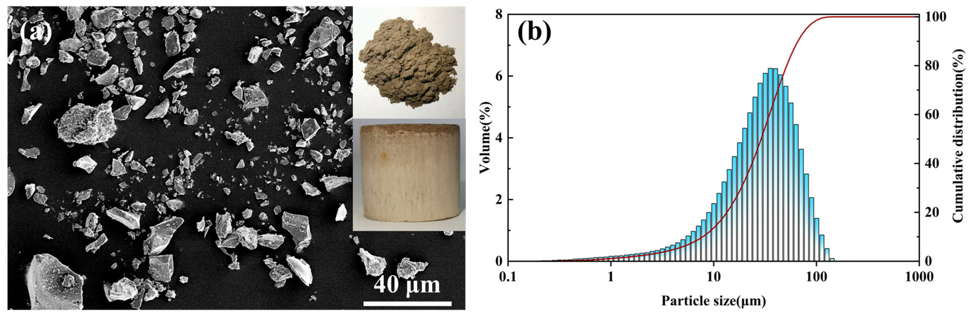
This study uses a laboratory-prepared lunar regolith simulant as the raw material. The XRF analysis results in Table 1 show that the elemental composition of the simulant closely resembles that of lunar regolith [22]. As shown in Figure 1a, the particles exhibit irregular polyhedral morphologies with relatively sharp edges. Particle size analysis (Figure 1b) indicates a median diameter (D50) of 28.92 μm, with most particles below 75 μm. Prior to experimentation, the powder was dried at 110 °C for 12 h in a forced air oven to remove moisture. The dried powder was then uniaxially compacted at 10 MPa in a die with a 15 mm inner diameter to form cylindrical green bodies approximately 10 mm in height (Figure 1a).

2.2. Microwave Sintering Procedure

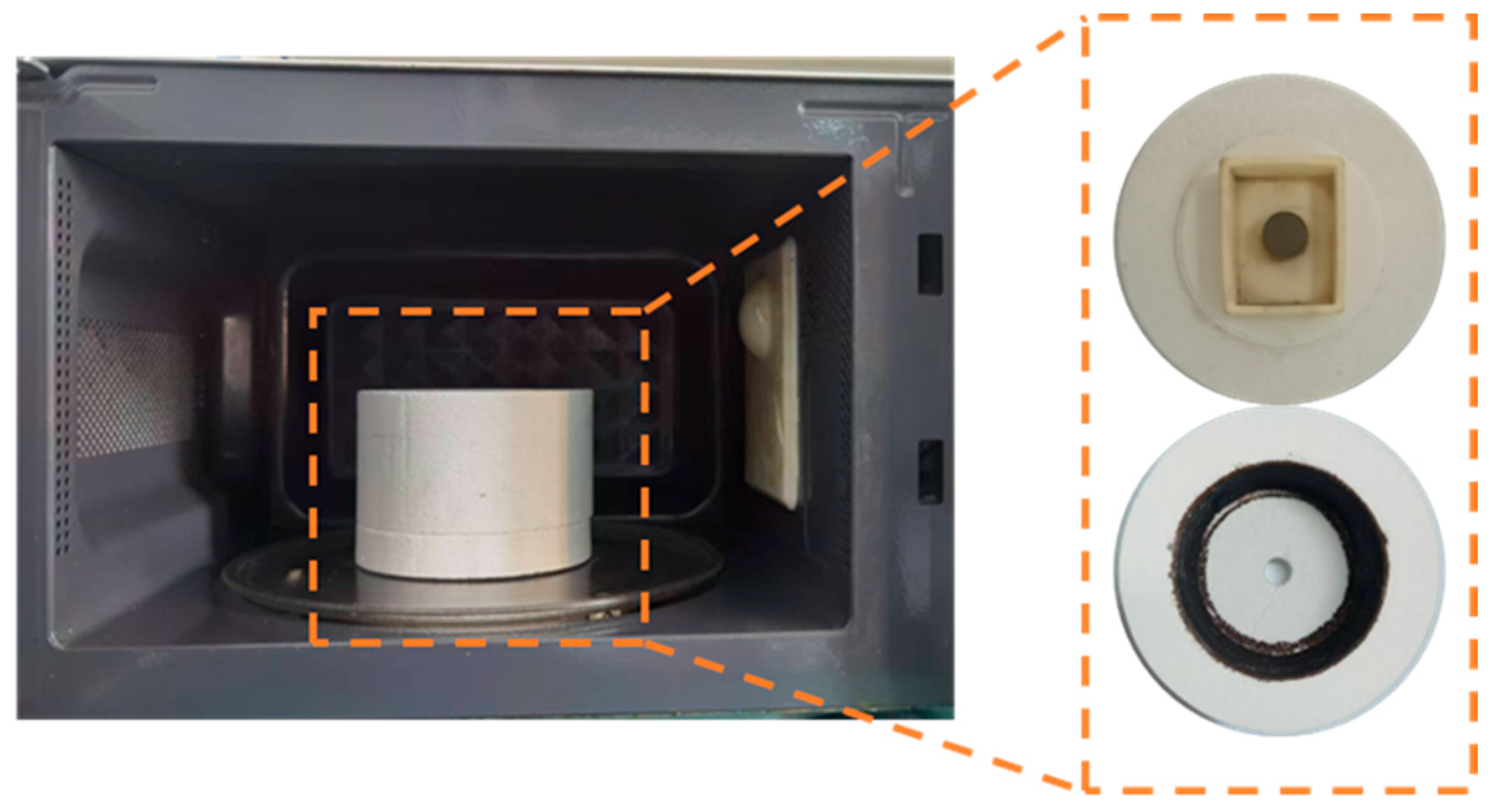
The microwave sintering experiments were conducted using a microwave oven (frequency: 2.45 GHz, rated output power: 750 W) as the energy source, with all experiments carried out in continuous wave mode at maximum power. The heating chamber consisted of a ceramic fiber microwave furnace (Dingrong High Temperature Materials, Zibo, China), with an inner diameter of 80 mm and a height of 45 mm. The furnace’s outer layer was constructed from ceramic fiber, while the inner walls were coated with silicon carbide (SiC). A schematic of the experimental setup is shown in Figure 2. SiC, acting as an efficient microwave absorber, facilitates the effective conversion of microwave energy into heat [23]. To ensure consistent heating conditions, the SiC coating used was either brand new or had been used fewer than 20 times, with no noticeable degradation or peeling of the coating observed before or after each experiment.
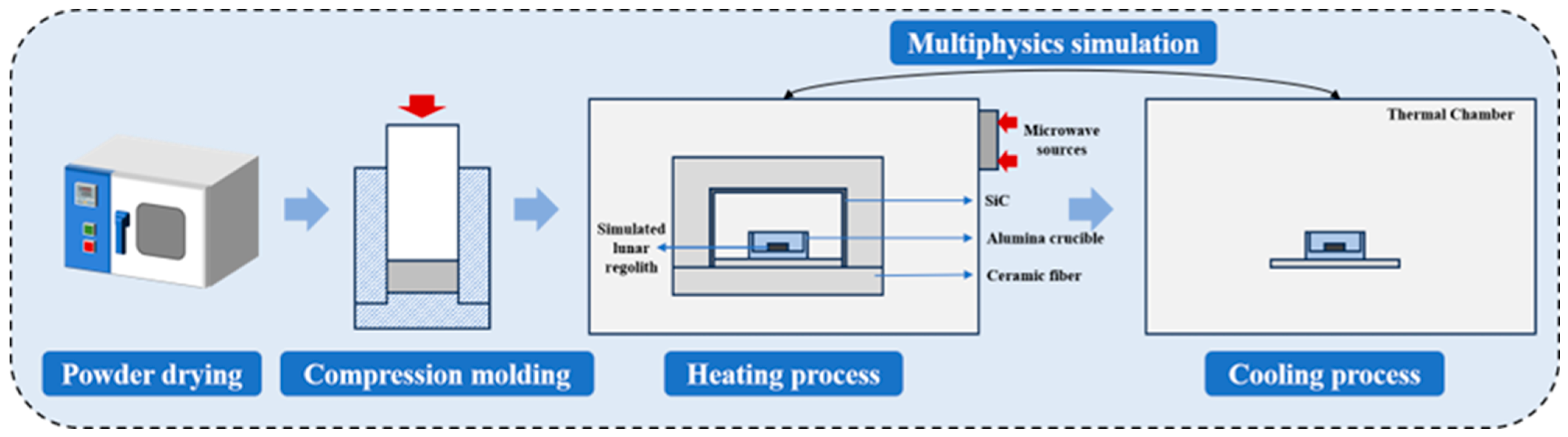
The specific sintering process is illustrated in Figure 3. The cylindrical green body was first placed inside a corundum crucible. This crucible assembly was then positioned within the ceramic fiber microwave kiln, which was centrally located in the microwave oven cavity. Prior to initiation, the microwave power and heating duration were set. The process concluded automatically when the preset heating time elapsed.

2.3. Cooling Process

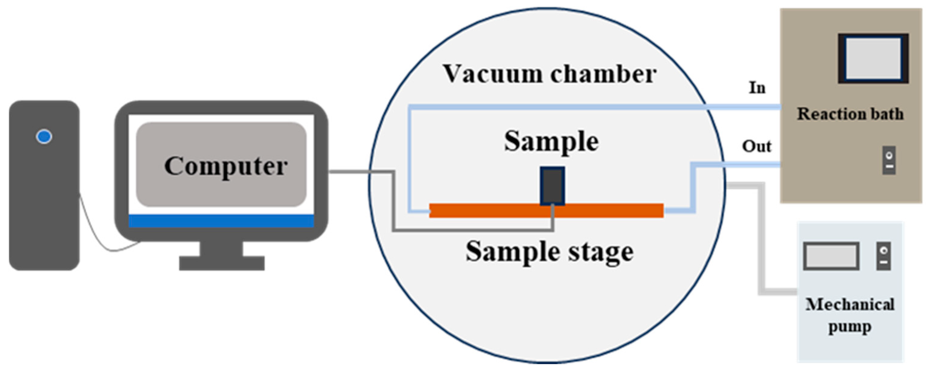
Controlled cooling of the sintered samples was achieved using a low-temperature chamber (Figure 4). Immediately after microwave heating, the sample was transferred to the chamber, which was pre-stabilized at the target temperature. A K-type thermocouple in contact with the sample surface recorded the temperature in real time to plot the cooling curve. In this study, the cooling rate was quantified as the average rate of temperature decrease from 1000 °C to 200 °C.

2.4. Characterization

The particle size distribution of the lunar regolith simulant in deionized water was measured using a laser particle size analyzer (Mastersizer 2000, Malvern Instruments Ltd., Malvern, UK). Phase analysis was performed via X-ray diffraction (XRD; Rigaku Ultima IV, Tokyo, Japan), with a scan speed of 5°/s, a scan range of 10–90°, and a copper target. X-ray photoelectron spectroscopy (ESCALAB 250Xi, Thermo Fisher Scientific, Waltham, MA, USA) was employed to characterize the binding energy and valence states of surface elements on samples sintered at different cooling rates, and the XPS tests were conducted under an inert gas atmosphere. Microstructural and elemental analyses were conducted using scanning electron microscopy (SEM) coupled with energy-dispersive X-ray spectroscopy (EDS) (JSM-7610F, JEOL, Tokyo, Japan).

3. Results and Discussion

3.1. Model Formulation

To predict the temperature and stress distributions during sintering and cooling, a three-dimensional finite element model was developed using COMSOL Multiphysics 6.3 (COMSOL AB, Stockholm, Sweden). The model geometry replicates the experimental apparatus. By coupling the Solid Heat Transfer and Solid Mechanics modules, the simulation concurrently solves for the transient thermal and stress fields. In this study, we determine crack initiation by comparing the maximum tensile stress with the material’s ultimate tensile strength. This approach effectively simulates crack initiation. However, the current model is limited to simulating crack initiation due to thermal stresses and does not account for crack propagation. Nevertheless, this method provides a reliable framework for modeling the initial generation of cracks. Future work will incorporate brittle damage models or phase-field methods to further simulate crack propagation and gain a more comprehensive understanding of crack evolution.
The present model rests on several simplifying assumptions. First, the temperature dependence of material properties is neglected. While this assumption may lead to prediction errors under extreme temperatures, it allows the model to focus on the critical relationship between cooling rate and thermal stress. Second, the density of the weathered-layer green body is assumed constant, and potential phase transformations are ignored. Although this simplification may overlook some microscopic changes, it remains effective for capturing the overall trends in thermal stress during cooling. Third, the emissivity of all kiln interior surfaces is fixed at 0.85. This simplification may affect the accuracy of thermal radiation calculations at high temperatures, but it facilitates the overall heat transfer modeling. Fourth, the current model assumes a homogeneous material, neglecting the inherent microstructural heterogeneity of the regolith, such as variations in particle size, mineral composition, and phase distribution. While this assumption simplifies the simulation and focuses on the overall thermal stress distribution, it may not fully capture the effects of these local microstructural variations on crack initiation and propagation.
The energy for microwave sintering originates from the dissipation of electromagnetic waves within the material. This wave propagation and interaction are governed by a generalized Helmholtz equation, which is derived from Maxwell’s equations [24]:
× 1 μ r ( × E ) k 0 2 ( ε r j σ ω ε 0 ) E = 0
where E is the electric field intensity vector, ω is the angular frequency, ε 0 is the vacuum permittivity, ε r   =   ε j ε is the complex relative permittivity of the material, μ r is the relative permeability, and σ is the electrical conductivity.
Based on Fourier’s heat-transfer equation, the temperature distribution within the material can be obtained through a coupled heat transfer and electromagnetic heating model [24]:
ρ C p T t = ( k   T ) + Q em
where ρ is the density, C p is the specific heat capacity at constant pressure, k is the thermal conductivity, Q em = 1 2 ω ε 0 ε E 2 is the electromagnetic heat source term.
Under high-temperature conditions, heat transfer in the air is dominated by radiation. Therefore, thermal radiation is the primary mode of heat exchange between the sintered body surface and the surroundings. This model determines the net radiative heat flux by solving the surface energy balance equation [25]:
J = ε e b ( Τ ) + ρ d G
where e b ( Τ ) = n 2 σ T 4 is the blackbody emissive power, ε is the surface emissivity, and ρ d is the diffuse reflectivity.
Thermal stress within the sintered body arises from thermoelastic deformation caused by non-uniform temperature distribution during cooling [26]. The temporal evolution of thermal stress was simulated using transient dynamic equations [27], including the inertia term to account for the dynamic effects of temperature gradients during the cooling process. Despite the relatively low cooling rate, these effects may still influence the development of stress:
ρ 2 u t 2 = S + f v
where S is the divergence of the stress tensor, f v is the body force vector, ρ is the material density, u is the displacement vector, and t is time.
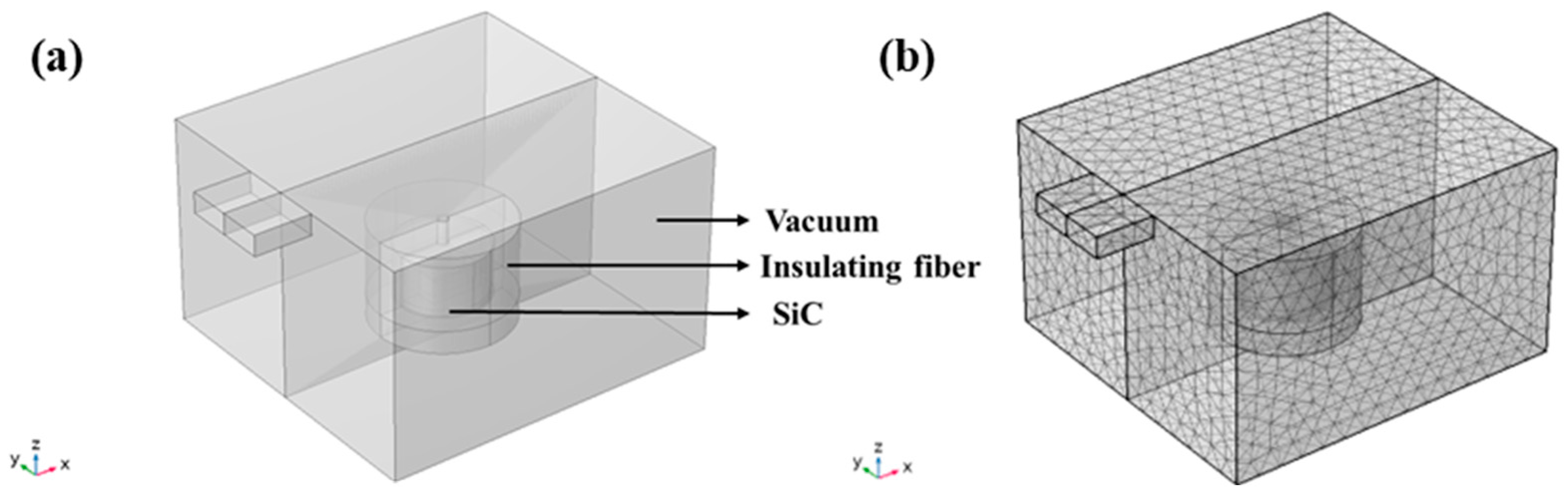
A three-dimensional model, based on the experimental setup in Figure 2, was developed (Figure 5a). It consists of a microwave cavity, a ceramic fiber insulation layer, a silicon carbide layer, and the green-body sample. The geometry was discretized using tetrahedral elements, with local mesh refinement in critical regions to ensure accuracy. The final mesh comprises 78,590 tetrahedral elements (Figure 5b). The total degrees of freedom considered in the simulation are 613,025, with 60,134 internal degrees of freedom, reflecting the degrees of freedom not restricted by boundary conditions within the model. Additionally, each node in the model has 7 degrees of freedom: 3 electric field components (Ex,Ey,Ez), 1 temperature degree of freedom (T), 3 displacement components (ux,uy,uz). For boundary nodes, an additional degree of freedom for surface radiation (J).
The key physical, dielectric, and thermal properties of all materials used in the model are listed in Table 2. In the electromagnetic simulation, a rectangular waveguide with an input power of 750 W was modeled, and the microwave cavity walls were defined as impedance boundaries (TE10 mode, 2.45 GHz). The rectangular waveguide consists of two input ports, with one port measuring 39 × 18 mm. To simulate cooling under different environmental temperatures, a surface-to-ambient radiation boundary condition was applied to the heated kiln surface, and radiative heat transfer between the SiC layer and the sample surface was modeled as surface-to-surface radiation. Finally, a fully coupled electromagnetic-thermal-stress multiphysics simulation was performed to study the transient temperature and stress evolution in the samples.

3.2. Simulation of the Cooling Process

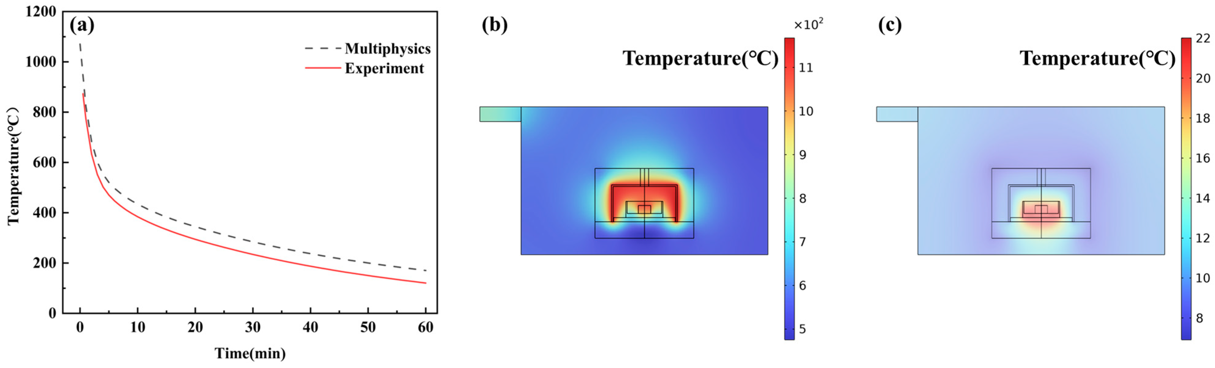
To validate the effectiveness of the multiphysics coupled model, the temperature evolution of lunar regolith simulant during the cooling process was experimentally measured in this study. As shown in Figure 6a, the simulated temperature curve closely matches the experimentally measured cooling trajectory, indicating that the model accurately reproduces the actual thermal evolution behavior of the sintered body. Figure 6b,c presents the temperature field distributions at the end of the sintering stage and upon completion of cooling, respectively. The simulation results are consistent with existing research findings [21]. The analysis shows that the regolith material reached the preset sintering temperature and formed a significant temperature gradient relative to the surrounding environment. According to thermoelastic theory, such a sharp temperature gradient is the direct cause of the high thermal stresses generated on the material surface.

3.3. Stress Evolution During Cooling

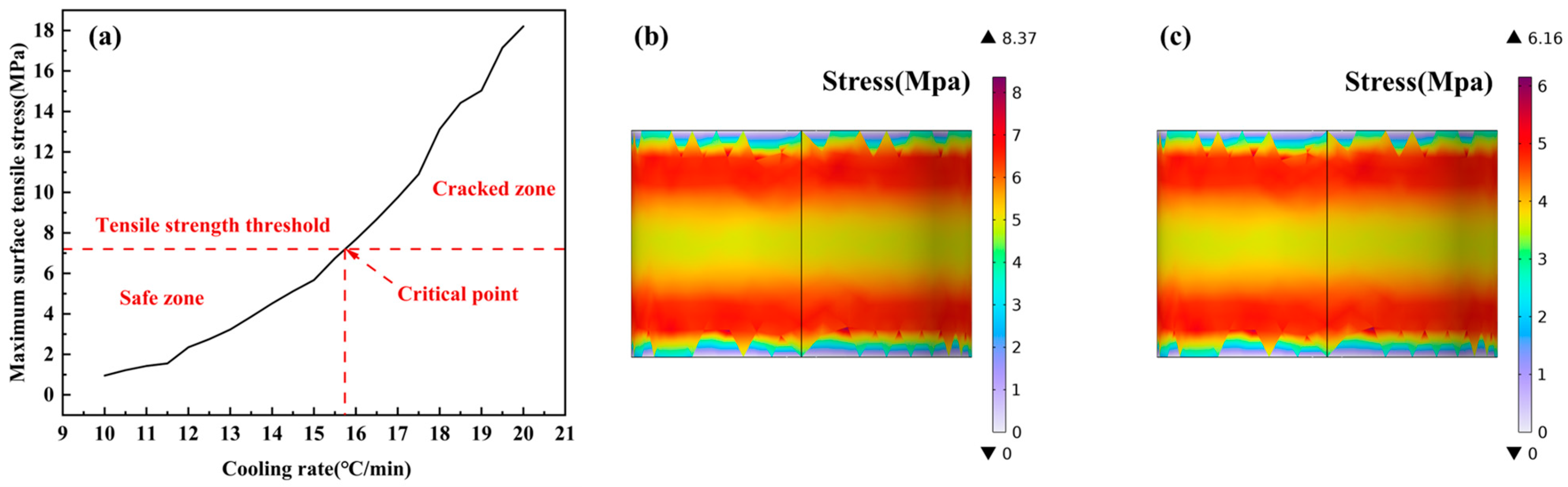
Based on this framework, the model further investigated the influence of the cooling rate on the thermal stress at the surface of the sintered body. The maximum thermal stress is represented by the first principal stress obtained from the simulation results. Figure 7a displays the simulated maximum surface thermal stress of the sintered regolith under different cooling rates. A significant positive correlation is observed: a faster cooling rate leads to higher maximum surface tensile stress in the sintered regolith. When the cooling rate reaches 16 °C/min, the induced tensile stress exceeds the average tensile strength threshold (7.2 MPa) of the uncracked samples in this experiment, causing the sample to enter the “cracking zone” indicated in the figure. Furthermore, the stress distribution contour plot (Figure 7b) reveals that high-stress regions are notably concentrated at both ends of the sintered block, forming typical stress concentration zones. This indicates that faster cooling rates exacerbate the non-uniform shrinkage between the surface and the interior of the material, thereby amplifying the thermo-elastic mismatch effect. Based on these findings, this study proposes that the cooling rate should be controlled below 15 °C/min. As shown in Figure 7b, within this safe rate, the overall thermal stress level is reduced below the threshold, ensuring the surface integrity of the sintered body.
It is important to note that the current multiphysics simulations do not include a damage model, which may limit the accuracy in predicting crack formation. While the model effectively describes thermal stress evolution, crack initiation and propagation are not precisely simulated. Future efforts will focus on incorporating damage evolution mechanisms into the simulations to provide a more comprehensive prediction of material failure under varying cooling conditions.
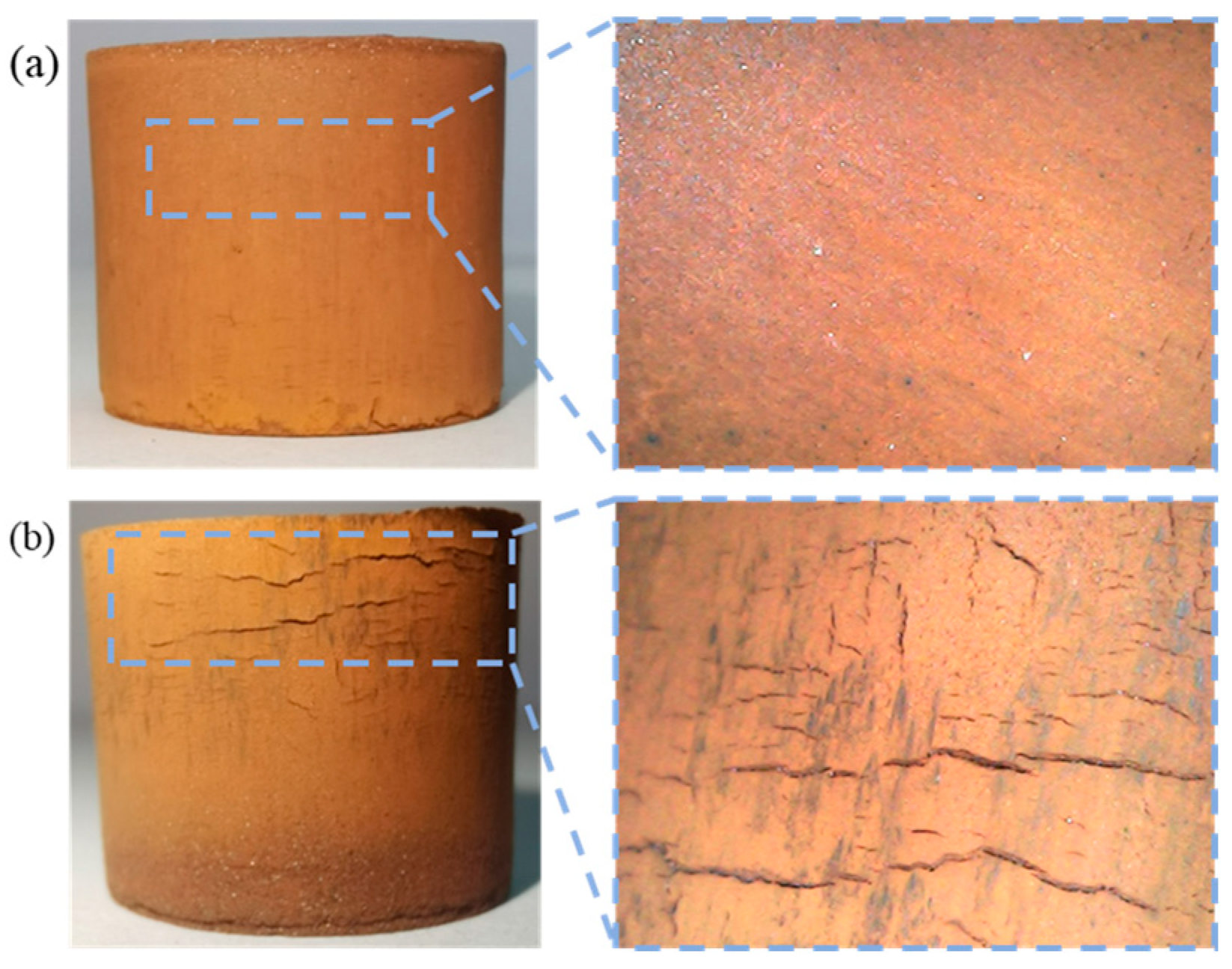
To validate the accuracy of the simulation predictions, macroscopic morphology observations were conducted on sintered bodies prepared at different cooling rates, with the results shown in Figure 8. At a cooling rate of 15 °C/min, the sample surface remained intact, and no macroscopic cracks were observed (Figure 8a). This result is consistent with the simulation prediction (Figure 7c), indicating that the surface thermal stress of the sintered body remained below the average tensile strength under this condition. However, when the cooling rate was increased to 16 °C/min, significant macroscopic cracks appeared on the sample surface (Figure 8b). More importantly, the crack initiation sites showed a high degree of coincidence with the stress concentration zones predicted by the simulation (Figure 7b). This agreement between prediction and experiment not only confirms the accuracy of the critical cooling rate but also validates the reliability of the model established in this study for predicting structural failure in sintered bodies.

3.4. Microstructural Changes

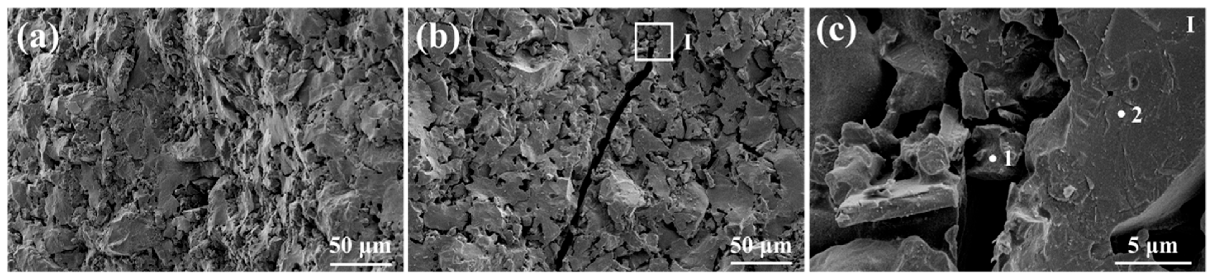
As shown in Figure 9, the cooling rate has a significant impact on the microstructure of the sintered samples. Under the cooling condition of 15 °C/min, the sample exhibits a continuous structure containing only a few isolated pores (Figure 9a). In contrast, when the cooling rate was increased to 16 °C/min, evident microcracks appeared within the sample (Figure 9b). To reveal the local conditions for crack initiation, Energy Dispersive Spectroscopy (EDS) analysis was performed on the crack path and the adjacent matrix (Figure 9c). As shown in Table 3, the results indicate that the contents of Si and Al on the crack path (10.78 at.% and 4.89 at.%, respectively) were significantly lower than those in the matrix region (15.15 at.% and 6.83 at.%), while the crack path contained 12.08 at.% of C. Conversely, the matrix region was relatively enriched in Ti (0.71 at.%) and Fe (2.06 at.%). This micro-heterogeneity in chemical composition suggests that cracks preferentially initiate and propagate in regions with lower Si/Al content and the presence of C.
The phenomenon that crack paths preferentially propagate through the relatively brittle, C-rich regions can be explained by the microstructural heterogeneity of the material. C-rich regions are typically more brittle, and the lower Si/Al content in these regions results in poorer mechanical strength, making them more prone to crack initiation and propagation [30]. In contrast, Al-rich phases usually exhibit higher toughness, which can impede crack propagation through local toughening or crack deflection mechanisms [31]. The relative enrichment of Ti and Fe may enhance the crack resistance of the matrix region, as the enrichment of these elements helps improve the local toughness of that region, thereby slowing down crack propagation [32]. Additionally, under rapid cooling conditions, the thermal expansion differences between regions with different chemical compositions can easily induce stress concentration at their interfaces, providing favorable conditions for microcrack formation [30,31,32].
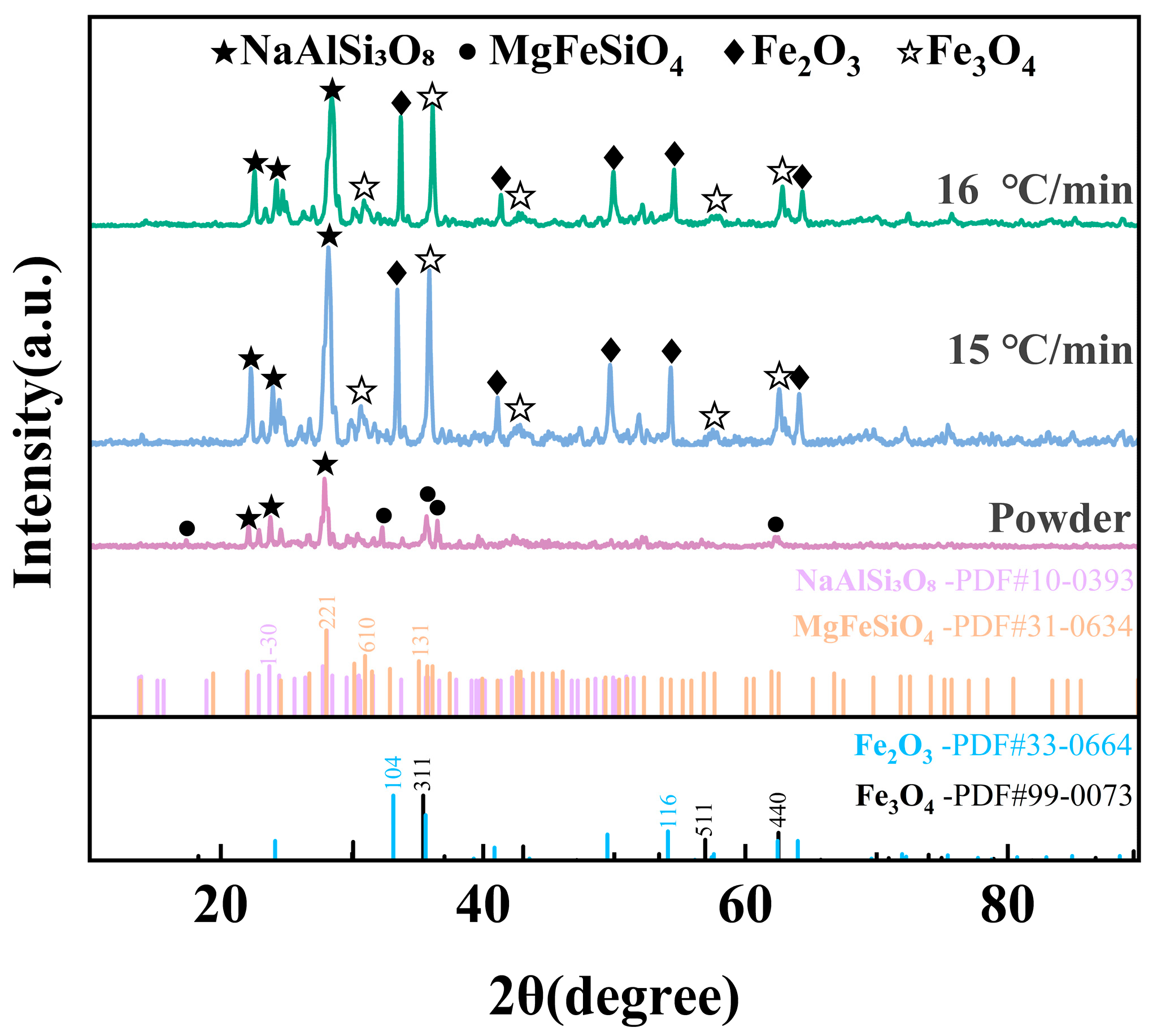
Figure 10 shows the XRD patterns of the raw simulant regolith powder and the sintered bodies at different cooling rates. The raw powder is primarily composed of olivine (MgFeSiO4) and albite (NaAlSi3O8), which is consistent with the typical mineral composition of lunar basalt [33]. During microwave sintering, the high temperatures generated by microwave energy cause the oxidative decomposition of olivine, leading to the formation of magnetite and hematite [34]. The positions of all diffraction peaks remain unchanged, indicating that there is no significant lattice distortion or solid solution formation during the sintering process. The phase evolution described above primarily results from the oxidative decomposition of olivine under the high-temperature conditions of microwave sintering. The thermo-elastic mismatch induced by this phase transformation acts as a microscopic factor, intensifying surface thermal stress and contributing to cracking during the cooling process. Specifically, the differences in thermal expansion coefficients (CTE) between phases such as olivine, magnetite, and hematite lead to the accumulation of thermal stress during cooling, which ultimately promotes the formation of microcracks. The thermoelastic properties of these phases, including elastic moduli, Poisson’s ratios, and coefficients of thermal expansion, are summarized in Table 4 [35,36,37,38,39]. The specific reaction pathway can be described as follows:
6 M g F e S i O 4 + O 2 2 F e 3 O 4 + 3 M g 2 S i O 4 + 6 S i O 2
4 F e 3 O 4 + O 2 6 F e 2 O 3
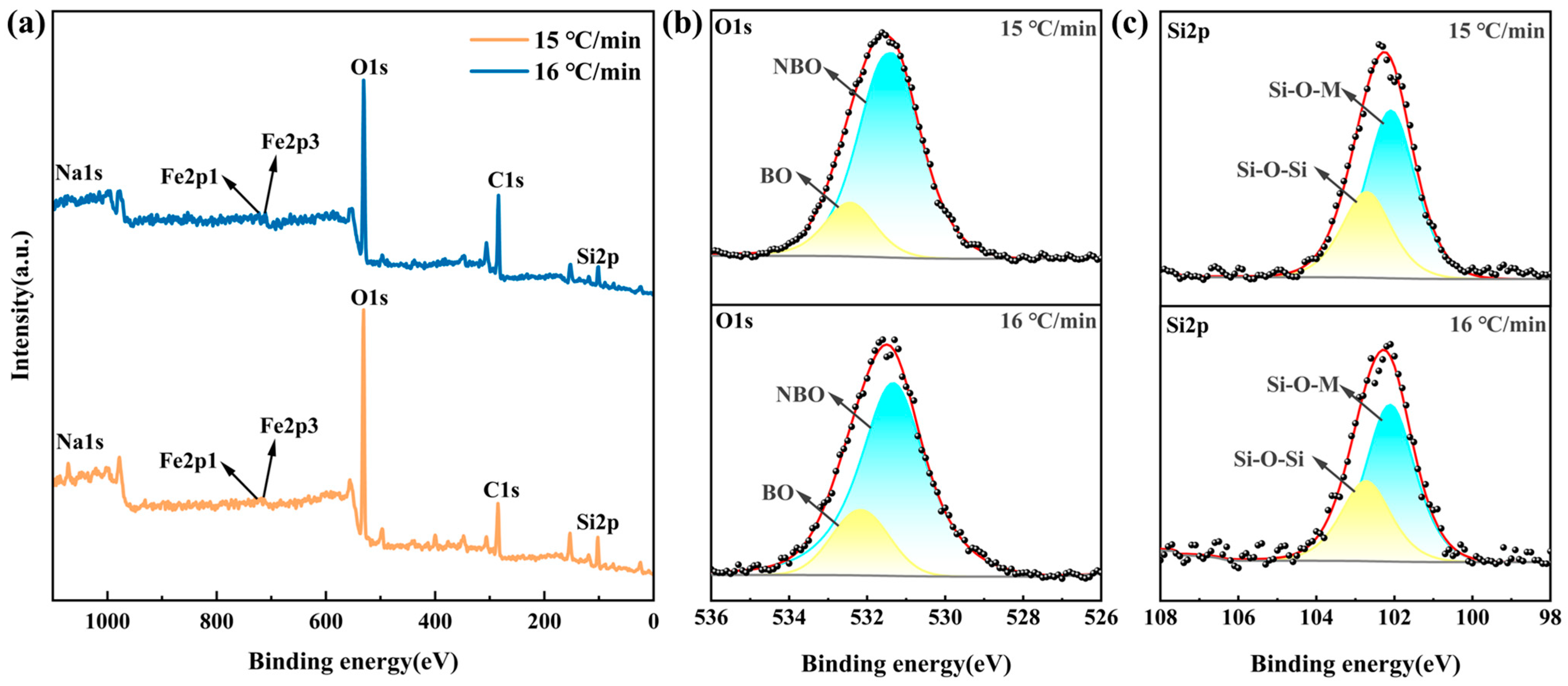
The XPS analysis results of sintered samples at different cooling rates are shown in Figure 11. The survey spectrum (Figure 11a) confirms that the sample surface primarily contains elements such as O, Si, Fe, and C. The C 1s peak at 284.8 eV was used as a charge correction reference [40]. Both the O 1s and Si 2p high-resolution spectra could be deconvoluted into two characteristic peaks. In the O 1s spectrum, the area ratio of the non-bridging oxygen (NBO, 531.2 eV) peak to the bridging oxygen (BO, 532.5 eV) peak remained stable at approximately 4:1. This ratio is highly consistent with the intensity ratio between the Si-O-M bond (102.1 eV) and the Si-O-Si bond (103.3 eV) in the Si 2p spectrum. These results consistently indicate that, during the cooling process, network modifier cations in the high-temperature melt continuously disrupted the silicate network, ultimately leading to a surface chemical state dominated by non-bridging oxygen. Both this finding and the disappearance of the silicate phase point towards the formation of a silicate glass phase rich in network modifiers. Furthermore, the mismatch arising from the difference in thermal expansion coefficients between this brittle glass phase and the iron-rich crystalline phase precipitated during cooling constitutes the direct origin of the microscopic thermal stress.

4. Conclusions

This study systematically investigates the thermal stress evolution and critical process conditions during the cooling of simulated lunar regolith microwave-sintered bodies by establishing an electromagnetic-thermal-stress multiphysics coupling model and validating it through ground-based experiments. The main findings are as follows:
  • The cooling rate is a key factor controlling the surface integrity of sintered bodies. Research indicates that when the cooling rate is below 15 °C/min, the surface thermal stress remains below the material’s tensile strength threshold, effectively preventing crack formation. When the cooling rate exceeds 16 °C/min, the surface thermal stress surpasses this threshold, leading to crack initiation and propagation.
  • Under rapid cooling conditions, a silicate glass phase forms on the surface. Cracks preferentially initiate in regions with lower Si/Al content and the presence of C impurities, propagating due to thermo-elastic mismatch.
  • XRD and XPS analysis results show that during sintering, the olivine phase undergoes oxidative decomposition, forming new phases such as magnetite (Fe3O4) and hematite (Fe2O3). The surface chemical state is dominated by non-bridging oxygen (NBO), which exacerbates thermal stress and contributes to crack formation.
  • A safe cooling rate of 15 °C/min is identified, ensuring the surface integrity required for microwave sintering.
In conclusion, this study provides an in-depth theoretical analysis of thermal stress evolution during microwave sintering and further validates the key role of cooling rate and phase transformations in crack formation.

Author Contributions

Conceptualization, Q.W.; methodology, Z.X.; software, Z.X.; validation, Q.W.; formal analysis, Z.X.; investigation, Z.X.; resources, Y.L.; data curation, Q.W.; writing—original draft preparation, Z.X.; writing—review and editing, Q.W.; visualization, Z.X.; supervision, Q.W.; project administration, Q.W.; funding acquisition, Q.W. All authors have read and agreed to the published version of the manuscript.

Funding

This work was supported by the Natural Science Foundation of Hebei Province (D2024202002), the Shijiazhuang City Science and Technology Cooperation Special Program (SJZZXB25007), and the Fund for Innovative Research Groups of Natural Science Foundation of Hebei Province (A2024202045).

Institutional Review Board Statement

Not applicable.

Informed Consent Statement

Not applicable.

Data Availability Statement

The original contributions presented in this study are included in the article. Further inquiries can be directed to the corresponding author.

Conflicts of Interest

The authors declare no conflicts of interest.

References

  1. Leone, G.; Ahrens, C.; Korteniemi, J.; Gasparri, D.; Kereszturi, A.; Martynov, A.; Schmidt, G.W.; Calabrese, G.; Joutsenvaara, J. Sverdrup-Henson crater: A candidate location for the first lunar South Pole settlement. iScience 2023, 26, 107853. [Google Scholar] [CrossRef] [Scilit]
  2. Wang, C.; Jia, Y.; Xue, C.; Lin, Y.; Liu, J.; Fu, X.; Xu, L.; Huang, Y.; Zhao, Y.; Xu, Y. Scientific Objectives and Payload Configuration of the Chang’E-7 Mission. Natl. Sci. Rev. 2023, 11, nwad329. [Google Scholar] [CrossRef] [Scilit] [PubMed]
  3. Sanders, G.B.; Larson, W.E. Progress Made in Lunar In Situ Resource Utilization under NASA’s Exploration Technology and Development Program. J. Aerosp. Eng. 2013, 26, 5–17. [Google Scholar] [CrossRef] [Scilit]
  4. Bao, C.; Wang, Y.; Pearce, G.; Mushtaq, R.T.; Liu, M.; Zhao, P. In-Situ Additive Manufacturing with Lunar Regolith for Lunar Base Construction A Review. Appl. Mater. Today 2024, 41, 102456. [Google Scholar] [CrossRef] [Scilit]
  5. Azami, M.; Kazemi, Z.; Moazen, S.; Dubé, M.; Potvin, M.-J.; Skonieczny, K. A Comprehensive Review of Lunar-Based Manufacturing and Construction. Prog. Aerosp. Sci. 2024, 150, 101045. [Google Scholar] [CrossRef] [Scilit]
  6. Ellery, A. Leveraging in Situ Resources for Lunar Base Construction. Can. J. Civ. Eng. 2022, 49, 657–674. [Google Scholar] [CrossRef] [Scilit]
  7. Zheng, X.; Zhao, C.; Sun, X.; Dong, W. Lunar Regolith Geopolymer Concrete for In-Situ Construction of Lunar Bases: A Review. Polymers 2024, 16, 1582. [Google Scholar] [CrossRef] [Scilit]
  8. Hossain, S.S.; Bullard, J.W. Sintering of Lunar Regolith: A Review. Acta Astronaut. 2025, 231, 153–174. [Google Scholar] [CrossRef] [Scilit]
  9. Liu, B.; Sun, P.; Yao, W.; Li, T.; Xu, W. Research Progress on the Adaptability of Lunar Regolith Simulant-Based Composites and Lunar Base Construction Methods. Int. J. Min. Sci. Technol. 2024, 34, 1341–1363. [Google Scholar] [CrossRef] [Scilit]
  10. Farries, K.W.; Visintin, P.; Smith, S.T.; van Eyk, P. Sintered or Melted Regolith for Lunar Construction: State-of-the-Art Review and Future Research Directions. Constr. Build. Mater. 2021, 296, 123627. [Google Scholar] [CrossRef] [Scilit]
  11. Song, L.; Xu, J.; Tang, H.; Liu, J.; Liu, J.; Li, X.; Fan, S. Vacuum Sintering Behavior and Magnetic Transformation for High-Ti Type Basalt Simulated Lunar Regolith. Icarus 2020, 347, 113810. [Google Scholar] [CrossRef] [Scilit]
  12. Han, W.; Ding, L.; Cai, L.; Zhu, J.; Luo, H.; Tang, T. Sintering of HUST-1 Lunar Regolith Simulant. Constr. Build. Mater. 2022, 324, 126655. [Google Scholar] [CrossRef] [Scilit]
  13. Zhang, X.; Khedmati, M.; Kim, Y.; Shin, H.; Lee, J.; Kim, Y.; Cui, B. Microstructure Evolution during Spark Plasma Sintering of FJS-1 Lunar Soil Simulant. J. Am. Ceram. Soc. 2019, 103, 899–911. [Google Scholar] [CrossRef] [Scilit]
  14. Iantaffi, C.; Leung, C.L.A.; Maddison, G.; Bele, E.; Hocine, S.; Snell, R.; Rack, A.; Meisnar, M.; Rohr, T.; Todd, I. Laser Additive Manufacturing of Lunar Regolith Simulant: New Insights from in Situ Synchrotron X-Ray Imaging. Addit. Manuf. 2025, 101, 104711. [Google Scholar] [CrossRef] [Scilit]
  15. Dang, F.; Wang, Z.; Li, Y.; Sun, W.; Zhou, Y.; Zhou, C. Investigation of the Melting Behavior of Laser-Melted Lunar Regolith Simulant for in-Situ Construction. J. Mater. Res. Technol. 2025, 36, 4574–4584. [Google Scholar] [CrossRef] [Scilit]
  16. Zhang, Y.; Shaw, M.; Brooks, G.; Rhamdhani, M.A.; Guo, C.; Han, Z.; Jackson, T.; Judkins, G. Investigation of Heat Transfer Processes in Multi-Sized Solar-Sintered Regolith for Lunar ISRU Program. Int. J. Heat Mass Transf. 2023, 214, 124387. [Google Scholar] [CrossRef] [Scilit]
  17. Cesaretti, G.; Dini, E.; De Kestelier, X.; Colla, V.; Pambaguian, L. Building Components for an Outpost on the Lunar Soil by Means of a Novel 3D Printing Technology. Acta Astronaut. 2014, 93, 430–450. [Google Scholar] [CrossRef] [Scilit]
  18. Taylor, L.A.; Meek, T.T. Microwave Sintering of Lunar Soil: Properties, Theory, and Practice. J. Aerosp. Eng. 2005, 18, 188–196. [Google Scholar] [CrossRef] [Scilit]
  19. Kim, Y.-J.; Jin, H.; Zhuang, L.; Yeom, S.; Lee, J.; Shin, H.-S. Effect of Compaction Pressure on the Microstructural, Mechanical, and Thermal Properties of Microwave-Sintered KLS-1 Lunar Regolith Simulant. Case Stud. Constr. Mater. 2025, 23, e05449. [Google Scholar] [CrossRef] [Scilit]
  20. Go, G.-H.; Jin, H.; Lee, J.; Kim, Y.-J.; Shin, H.-S. Electromagnetic–Thermal Coupled Modeling for Optimizing the Microwave Sintering of Homogeneous Block of KLS-1 Lunar Regolith Simulant. Int. Commun. Heat Mass Transf. 2025, 161, 108544. [Google Scholar] [CrossRef] [Scilit]
  21. Liu, Z.; Li, J.; Yang, X.; Ding, Y.; Meng, S. Sintering of Lunar Regolith Simulants Using a Domestic Microwave: A Rapid and Energy-Efficient Strategy for Construction Material Fabrication. J. Eur. Ceram. Soc. 2025, 45, 117047. [Google Scholar] [CrossRef] [Scilit]
  22. Zheng, Y.; Wang, S.; Ouyang, Z.; Zou, Y.; Liu, J.; Li, C.; Li, X.; Feng, J. CAS-1 Lunar Soil Simulant. Adv. Space Res. 2009, 43, 448–454. [Google Scholar] [CrossRef] [Scilit]
  23. Mohanty, A.; Patel, D.K.; Panigrahi, S.K. Susceptor Based Design Strategies for Enhancing Microwave Hybrid Heating Capability via Experimental Analysis,3D Multi-Physics Simulation and Parametric Optimization. Int. J. Therm. Sci. 2024, 196, 108674. [Google Scholar] [CrossRef] [Scilit]
  24. Patel, D.K.; Bhoi, N.K.; Singh, H. Microwave Heating Capabilities of Different Susceptor Material: Experimental and Simulation Study. Silicon 2021, 14, 6621–6635. [Google Scholar] [CrossRef] [Scilit]
  25. Badri, M.A.; Favennec, Y.; Jolivet, P.; Rousseau, B. Conductive-Radiative Heat Transfer within SiC-Based Cellular Ceramics at High-Temperatures: A Discrete-Scale Finite Element Analysis. Finite Elem. Anal. Des. 2020, 178, 103410. [Google Scholar] [CrossRef] [Scilit]
  26. Zhang, L. Harness the Internal Stress in Ceramics. J. Mater. 2025, 11, 101043. [Google Scholar] [CrossRef] [Scilit]
  27. Liao, Z.; Ma, S.; Li, S.; Wang, X.; Wan, T. Electromagnetic-Thermal-Stress Modeling of Antenna Array Based on Finite Element Domain Decomposition Method. IEEE Antennas Wirel. Propag. Lett. 2024, 23, 4323–4327. [Google Scholar] [CrossRef] [Scilit]
  28. Tamang, S.; Aravindan, S. 3D Numerical Modelling of Microwave Heating of SiC Susceptor. Appl. Therm. Eng. 2019, 162, 114250. [Google Scholar] [CrossRef] [Scilit]
  29. Bhatt, S.C.; Ghetiya, N.D. 3D Multiphysics Simulation of Microwave Heating of Bulk Metals with Parametric Variations. Chem. Eng. Process. Process Intensif. 2023, 184, 109271. [Google Scholar] [CrossRef] [Scilit]
  30. Liang, B.; Cuadra, J.; Hazeli, K.; Soghrati, S. Stress Field Analysis in a Stony Meteorite under Thermal Fatigue and Mechanical Loadings. Icarus 2020, 335, 113381. [Google Scholar] [CrossRef] [Scilit]
  31. Liu, Y.; Zhang, G.; Qiao, J.; Tang, X. Micromechanical Testing and Property Upscaling of Planetary Rocks: A Critical Review. Int. J. Min. Sci. Technol. 2024, 34, 1217–1241. [Google Scholar] [CrossRef] [Scilit]
  32. Mohamed, M.M.A.; Hamza, M.H.; Garvie, L.A.J.; Rabbi, M.F.; Cotto-Figueroa, D.; Asphaug, E.; Chattopadhyay, A. Mechanical and Failure Behavior of the Viñales (L6) Ordinary Chondrite: Linking Microstructure to Axial Splitting Fractures. Materialia 2026, 45, 102653. [Google Scholar] [CrossRef] [Scilit]
  33. Zhou, Z.; Zheng, X.; Wu, J. Dynamic Mechanical Properties of Lunar Regolith Based Geopolymer: Coupled Effects of Composition and Temperature. Case Stud. Constr. Mater. 2025, 23, e05417. [Google Scholar] [CrossRef] [Scilit]
  34. Drobot, N.F.; Noskova, O.A.; Baranchikov, A.E.; Khoroshilov, A.V.; Fomichev, S.V.; Krenev, V.A. Phase Composition of Metamorphosed Basalt and Its Sintering Products. Inorg. Mater. 2016, 52, 225–232. [Google Scholar] [CrossRef] [Scilit]
  35. Kroll, H.; Kirfel, A.; Heinemann, R. Axial Thermal Expansion and Related Thermophysical Parameters in the Mg, Fe Olivine Solid-Solution Series. Eur. J. Mineral. 2014, 26, 607–621. [Google Scholar] [CrossRef] [Scilit]
  36. Holcomb, G.R. A Review of the Thermal Expansion of Magnetite. J. Therm. Expans. Stud. 2023, 29, 123–145. [Google Scholar] [CrossRef] [Scilit]
  37. Chicot, D.; Mendoza, J.; Zaoui, A.; Louis, G.; Lepingle, V.; Roudet, F.; Lesage, J. Mechanical Properties of Magnetite (Fe3O4), Hematite (α-Fe2O3) and Goethite (α-FeO·OH) by Instrumented Indentation and Molecular Dynamics Analysis. Mater. Chem. Phys. 2011, 129, 862–870. [Google Scholar] [CrossRef] [Scilit]
  38. Mao, Z.; Fan, D.; Lin, J.-F.; Yang, J.; Tkachev, S.N.; Zhuravlev, K.; Prakapenka, V.B. Elasticity of Single-Crystal Olivine at High Pressures and Temperatures. Earth Planet. Sci. Lett. 2015, 426, 204–215. [Google Scholar] [CrossRef] [Scilit]
  39. Kroll, H.; Kirfel, A.; Heinemann, R.; Barbier, B. Volume Thermal Expansion and Related Thermophysical Parameters in the Mg, Fe Olivine Solid-Solution Series. Eur. J. Mineral. 2012, 24, 935–956. [Google Scholar] [CrossRef] [Scilit]
  40. Grey, L.H.; Nie, H.-Y.; Biesinger, M.C. Defining the Nature of Adventitious Carbon and Improving Its Merit as a Charge Correction Reference for XPS. Appl. Surf. Sci. 2024, 653, 159319. [Google Scholar] [CrossRef] [Scilit]
Figure 1. Microstructure and particle size distribution of the lunar regolith simulant: (a) SEM image and photograph; (b) particle size distribution curve.
Coatings 16 00222 g001
Figure 2. Schematic diagram of the microwave sintering experimental setup.
Coatings 16 00222 g002
Figure 3. Flowchart of the experiment.
Coatings 16 00222 g003
Figure 4. Schematic of the controlled-cooling experimental setup.
Coatings 16 00222 g004
Figure 5. Construction of the microwave sintering model: (a) 3D geometric model; (b) mesh generation schematic.
Coatings 16 00222 g005
Figure 6. Model validation and temperature field distribution: (a) comparison of experimental and simulated temperature curves; (b) contour plot of the temperature field at the end of sintering; (c) contour plot of the temperature field at the end of cooling.
Coatings 16 00222 g006
Figure 7. Influence of cooling rate on surface thermal stress: (a) relationship between stress and cooling rate; (b) stress distribution at 16 °C/min; (c) stress distribution at 15 °C/min.
Coatings 16 00222 g007
Figure 8. Surface morphology of sintered bodies under different cooling rates: (a) 15 °C/min; (b) 16 °C/min.
Coatings 16 00222 g008
Figure 9. SEM images of fracture surfaces of sintered samples at different cooling rates: (a) 15 °C/min; (b) 16 °C/min; (c) magnified view of the microcrack in (b). (c) shows a magnified view of Area I in (b), with points 1 and 2 indicating the locations of EDS point analysis.
Coatings 16 00222 g009
Figure 10. XRD patterns of the lunar simulant regolith powder and the sintered bodies at different cooling rates.
Coatings 16 00222 g010
Figure 11. XPS spectra of sintered samples at different cooling rates: (a) survey spectrum; (b) high-resolution O 1s spectrum; (c) high-resolution Si 2p spectrum.
Coatings 16 00222 g011
Table 1. Chemical composition of the lunar regolith simulant (wt.%).
OxideMass Fraction/wt.%
SiO244.48
Fe2O324.64
Al2O312.53
CaO10.6
TiO24.27
K2O2.69
MnO0.36
SrO0.24
ZrO20.08
Cr2O30.06
ZnO0.04
Total99.99
Table 2. Parameters of materials [21,28,29].
ParamaetersLunar Regolith SimulantSiCInsulating Fiber
Density (kg/m3)25603120275
Thermal conductivity (W/(m⋅K)1.291700.125
Specific heat (J/(kg⋅K))790625925
Relative permeability0.98011.011
Relative permittivity3.041910-
Loss tangent0.050.5-
Electrical conductivity (S/m)1 × 10−610-
Surface emissivity0.850.850.8
Young’s modulus (Gpa)100--
Poisson’s ratio0.24--
Table 3. EDS elemental analysis (at.%) of the crack origin and adjacent region.
ElementSpot 1 (at.%)Spot 2 (at.%)
O65.3167.85
Na2.32.84
Mg2.212.36
Al4.896.83
Si10.7815.15
Fe0.392.06
C12.08-
Ti-0.71
Total97.7697.80
Table 4. The Thermoelastic Properties of Olivine, Magnetite, and Hematite [35,36,37,38,39].
MaterislElastic Modulus (Gpa)Bulk Modulus (Gpa)Poisson’s RatioThermal Expansion Coefficient (10−6 °C−1)
Olivine130142–1570.285.3
Magnetite150–175183 ± 100.262.4–2.5
Hematite215–230230 ± 50.22–0.251.21–1.3
Disclaimer/Publisher’s Note: The statements, opinions and data contained in all publications are solely those of the individual author(s) and contributor(s) and not of MDPI and/or the editor(s). MDPI and/or the editor(s) disclaim responsibility for any injury to people or property resulting from any ideas, methods, instructions or products referred to in the content.