


Abstract
Silicon nitride (Si3N4) ceramic bearings inevitably contain crack-like defects, yet their compressive capacity degradation and crack-driven failure mechanisms remain unclear. This study proposes a discrete element method (DEM) numerical framework within PFC2D to simulate a bearing containing a single prefabricated crack. First, a bearing DEM model was established and calibrated to reproduce the compressive mechanical response. Then, particle deletion introduced controllable central cracks in the ball and raceway with prescribed inclination angles. Finally, displacement-controlled compression-splitting simulations, serving as a surrogate for a quasi-static overload scenario relevant to quality screening, tracked crack initiation, propagation, and failure modes; under a fixed raceway-crack inclination, crack length was varied to quantify size effects. Results show that a single crack markedly reduces compressive strength. Failure progresses through elastic deformation, crack propagation, and final fracture, with cracks initiating at stress concentrators near crack tips. Crack inclination significantly regulates capacity: raceway cracks are most detrimental near 45°, while ball cracks exhibit an overall decrease in initiation and peak stresses with increasing inclination (with local non-monotonicity). Crack length has a stronger weakening effect than inclination, with accelerated capacity loss beyond 0.3 mm and a pronounced drop in initiation stress beyond 0.6 mm. The framework enables controllable defect parametrization and micro-scale failure interpretation for defect sensitivity assessment under compressive overload. Thus, this study focuses on simulating monotonic fracture events to elucidate fundamental defect–property relationships, which provides a foundation distinct from the prediction of rolling contact fatigue life under cyclic service conditions.
1. Introduction
Rapid advances in high-end equipment demand bearings with extreme reliability, motivating the adoption of silicon nitride (Si3N4) ceramic bearings for their superior performance [1,2,3]. However, the intrinsic brittleness of ceramics makes their performance and lifespan highly sensitive to internal micro-defects, such as cracks, introduced during manufacturing or service [1]. These defects act as stress concentrators and dominate the fracture initiation process [4,5]. Therefore, establishing a quantitative understanding of how specific defect characteristics govern bearing failure is critical.
This necessitates a numerical approach capable of parametric defect analysis. The finite element method (FEM), while powerful for continuum analysis, encounters fundamental difficulties in modeling the discontinuous crack propagation from such discrete, internal flaws. This limitation is particularly severe for studies aiming to isolate the influence of controllable defect geometries (e.g., inclination, length). Here, the Discrete Element Method (DEM) offers a unique advantage. By representing materials as assemblies of discrete, bonded particles, DEM naturally accommodates the spontaneous initiation, propagation, and coalescence of cracks through bond breakage. This framework is uniquely suited for parametric defect investigation: it allows for the direct and precise introduction of flaws with predefined geometry into a complex component model, enabling both the quantification of macroscopic strength reduction and a micro-mechanical interpretation of the entire fracture process.
However, research employing the DEM-based parametric approach to systematically study the failure mechanisms of silicon nitride ceramic bearings containing a single, well-defined pre-existing crack remains scarce. It is acknowledged that in real manufacturing processes, the formation of micro-defects often involves stochastic factors, and a probabilistic framework is valuable for assessing component reliability at the population level. The present study, however, focuses on a deterministic analysis by introducing a single, well-defined prefabricated crack. This controlled approach allows us to isolate and quantify the fundamental effects of key geometric parameters (inclination angle, length) on the failure mechanism and load-bearing capacity. We posit that such deterministic results provide the essential mechanical insights and quantitative failure criteria that are necessary to inform and calibrate advanced probabilistic life-prediction models for bearings containing random defect distributions [6]. In real manufacturing, micro-defect formation involves stochastic factors, and a probabilistic framework is valuable for assessing component reliability at the population level [4]. However, traditional fracture mechanics is often ill-suited for handling the complexity of randomly distributed defects and their interactions within brittle ceramics [5,7]. The present study adopts a complementary, deterministic approach by introducing a single, well-defined prefabricated crack. This controlled methodology allows us to isolate and quantify the fundamental effects of key crack geometric parameters—specifically inclination angle and length—on the failure mechanism and load-bearing capacity. We posit that such deterministic results provide the essential mechanical insights and quantitative failure criteria necessary to inform and calibrate advanced probabilistic life-prediction models for bearings containing random defect distributions [4,8].
Numerical methods are crucial for such parametric defect analysis. In particular, the Discrete Element Method (DEM) demonstrates significant advantages in simulating fracture initiation, propagation, and coalescence in hard, brittle materials like ceramics [9,10,11]. DEM explicitly represents material granularity and can naturally simulate crack evolution without pre-defined paths, making it highly suitable for modeling the discrete failure processes stemming from pre-existing flaws [12]. For instance, Jiang et al. [13] employed a particle-based DEM model for silicon carbide ceramics with collinear pre-existing defects, revealing that the inclination angle had a more significant influence on micro-crack behavior than ligament length. This underscores DEM’s capability for targeted parametric studies on flaw geometry. Furthermore, DEM has been effectively applied to model damage and material removal in ceramic grinding processes, highlighting its robustness in simulating ceramic fracture under complex loading [14].
PFC2D, as a two-dimensional particle flow code based on DEM, is a powerful tool for simulating the motion and interaction of discrete particles [15,16]. It allows for the flexible configuration of particle properties and interaction laws to represent meso-scale mechanical behavior [17,18]. By explicitly modeling particles and bonds, PFC2D can directly simulate the generation and propagation of cracks from pre-defined defects, making it ideal for the parametric investigation of pre-cracked specimens [11,16]. This paper utilizes PFC2D to establish a model for a silicon nitride ceramic bearing containing a single prefabricated crack. This focused numerical experiment, integrating DEM’s strengths in brittle fracture simulation, aims to elucidate the influence of crack geometry on failure and provide theoretical insights for bearing performance research and life prediction.
Currently, research on the failure of brittle ceramic materials often employs pre-fabricated defects to analyze fracture modes and mechanical properties [5,9]. However, studies specifically investigating the failure mechanisms and load-bearing performance of ceramic bearings containing well-defined internal defects under compressive-shear stress states remain limited. Fractures in these hard, brittle materials predominantly initiate from inherent flaws, with crack-like defects being particularly critical [11,19]. For such discrete cracks, parameters like inclination angle and length are fundamental in controlling fracture initiation and propagation [12,13]. Existing research on ceramic bearing defects has primarily focused on empirical detection and macro-property correlation [2,20], or on process optimization for defect minimization [21]. While valuable, these approaches often do not isolate and quantify the direct mechanistic influence of a single crack’s geometry on the bearing’s structural integrity.
Consequently, a significant gap exists in employing Discrete Element Method (DEM) simulations to parametrically study silicon nitride ceramic bearings with a single, pre-defined crack. DEM is uniquely suited for this investigation because it explicitly models the granular microstructure of ceramics and can naturally simulate spontaneous crack initiation, propagation, and interaction without requiring pre-defined fracture paths [10,11]. This capability is essential for capturing the complex, discrete fracture processes that originate from a pre-existing flaw under multi-axial loading. No dedicated study has yet used DEM to systematically elucidate how controllable crack parameters (angle, length) govern the mechanical response, crack evolution patterns, and ultimate failure mode in ceramic bearing geometries.
Therefore, to address this gap, this study employs a DEM-based parametric approach using PFC2D. A single prefabricated crack is introduced into a silicon nitride ceramic bearing model. The core objective is to isolate and quantify the effects of the crack’s inclination angle and length on the global mechanical properties and localized fracture progression under compressive loading. By focusing on this fundamental “single crack” scenario, the study avoids the complexity of multiple defect interactions, aiming to establish clear quantitative relationships between defect geometry and bearing failure. This provides essential mechanical insights and criteria to inform more advanced probabilistic models for bearings with stochastic defect populations [4,8].
Furthermore, in real silicon nitride bearings, manufacturing-induced flaws such as voids, inclusions, or micro-cracks typically range from several microns to a few hundred microns. Non-destructive inspection techniques can reliably detect surface and sub-surface defects down to roughly 0.1–0.2 mm in ceramics. The 0.3 mm and 0.6 mm crack lengths studied here thus span a practically relevant defect-size window, bridging detectable flaw sizes and critical lengths that precipitate significant strength degradation under overload.
This paper is structured as follows. Section 2 introduces numerical simulation methods for brittle material defects and the discrete element modeling workflow, detailing contact model selection, bearing geometry modeling, loading configurations, and calculation methods for mechanical quantities such as stress–strain and elastic modulus. Section 3 details micro-parameter calibration experiments and pre-crack construction methods. It discusses the mechanical responses and crack propagation characteristics of ball cracks versus raceway cracks at different inclination angles, further analyzing strength threshold effects and failure variations caused by crack length changes under fixed inclination conditions. Section 4 summarizes key conclusions and patterns.
2. Materials and Methods
The discrete element model developed in this study employs a displacement-controlled, monotonic compression-splitting loading scheme. This numerical experiment is specifically designed to represent a simplified, quasi-static overload event, analogous to proof-loading or quality screening tests used in manufacturing to identify components with critical defects. The primary objective is to isolate and quantify the fundamental effects of a single crack’s geometry (angle, length, location) on the bearing’s compressive load capacity and fracture initiation mechanism. Consequently, it is crucial to delineate the boundaries of this simulation: it does not model the complex, multi-axial, and cyclic stress states characteristic of in-service rolling contact fatigue (RCF). Phenomena such as sub-surface stress evolution, wear, lubrication effects, and fatigue crack growth over millions of cycles are beyond the scope of this deterministic, single-loading-event analysis. The findings therefore provide essential insights into defect-criticality under static overload rather than predicting long-term operational life.
2.1. Numerical Simulation Analysis of Defects in Brittle Materials
Numerical simulation analysis is a method that employs computer simulation and mathematical modeling techniques to solve real-world problems [12,22]. It enables experimentation in virtual environments, predicting and analyzing the behavior and responses of various complex systems, thereby assisting scientists, engineers, and decision-makers in making more informed decisions.
Numerical simulation analysis employs numerous methods, with finite element analysis being the most prevalent. Common finite element software includes Ansys (Version 2022 R1), Abaqus (Version 2022), and HyperWorks (Version 2021). Finite element simulation, grounded in finite element theory, utilizes numerical computation to address the mechanical and thermodynamic properties of complex physical materials. It can model physical structures, material characteristics, and their behavior under various conditions—such as deformation and strain under stress, as well as changes under static and dynamic loads. However, in fracture studies of brittle materials, finite element simulation becomes unsuitable due to element discontinuities caused by crack initiation and frequent nonlinear behavior. Discrete element numerical simulation proves more appropriate, as it can model the motion of each particle within a brittle material aggregate—including fracture, separation, mixing, and flow—which the finite element method cannot achieve [23].
Multiple numerical methods exist for fracture analysis of brittle materials. Linear elastic fracture mechanics and nonlinear fracture mechanics provide theoretical frameworks for crack propagation based on the continuum medium assumption. Numerical implementation methods such as the boundary element method and numerical manifold method offer alternatives to traditional finite element methods.
However, the Discrete Element Method (DEM) offers unique advantages for simulating discontinuous crack initiation and propagation triggered by discrete internal defects in brittle ceramic materials. DEM characterizes materials as assemblies of discrete, cohesively bonded particles. Particles are treated as discrete units with defined volume, mass, and stiffness, interacting according to Newton’s second law. Material deformation and failure are simulated by calculating contact forces and displacements, with cracks forming spontaneously through bond breakage. This approach inherently captures crack spontaneous initiation, propagation, and coalescence without requiring predefined paths, making it well-suited for modeling discrete failure processes triggered by existing defects. Since its introduction in the 1990s, DEM has been widely applied to fracture propagation and failure studies of hard brittle materials, including ceramics [24].
2.2. Selection of Contact Models
In the PFC2D discrete element framework, the mechanical response of a material is governed by the selected contact model that defines the interactions between rigid particles. While the linear model and the parallel-bond model are foundational in geotechnical research, they present specific limitations when applied to high-performance ceramics like silicon nitride (Si3N4). The linear model is primarily suited for unbonded granular materials. The parallel-bond model, though capable of transmitting moments, often fails to accurately capture the high compressive-to-tensile strength ratios of ceramics, frequently resulting in non-physical particle rolling and inaccurate failure envelopes.
To address these challenges and accurately simulate the complex stress states—characterized by coupled splitting and compression—inherent in ceramic bearings, this study adopts the flat-joint (straight-joint) model within PFC2D. The flat-joint model represents the interface between two polygonal particles as a set of discrete planar segments, effectively creating an articulated contact zone that approximates a continuous bonding surface. Each interface is defined relative to an abstract contact plane located between Particle 1 and Particle 2. The geometry of the interface is characterized by the effective interface length, which spans a width of 2R along the contact plane, where R denotes the nominal particle radius. The contact plane is oriented by a unit normal vector pointing from the contact point xc on Particle 1 toward Particle 2. At each interface segment, a local coordinate system is established with the x-axis along the contact plane and the y-axis along the interface normal. The interface itself possesses a finite thickness tc, which governs the separation between the two particles and defines the region where contact forces and moments are transmitted. This discretized planar representation provides substantial rotational resistance and captures realistic grain interlocking behavior even after bond rupture, making it particularly suitable for simulating the coupled splitting-compression failure mechanisms observed in ceramics such as Si3N4 under compressive overload.
The flat-straight joint model encompasses both unconsolidated and consolidated modes, exhibiting distinct constitutive relationships and corresponding shear strengths, as illustrated by Equations (1) and (2).
In this equation, µ represents a constant value independent of temperature and stress variations. This is a common simplification in DEM simulations focused on the mechanical failure and crack propagation of brittle ceramics under quasi-static loading [25]. If , then := ; otherwise, :=
In this equation, σtb represents the tensile strength of the bond material, beyond which tensile failure occurs, cb represents cohesion, denotes the internal friction angle, and σb denotes the normal stress. If , then := ; otherwise, shear failure occurs in the bond. When , the bond undergoes tensile failure.
For numerical stability and realistic energy dissipation, damping coefficients of β_n = 0.3 and β_s = 0.3 were applied to the particle system. A friction coefficient of μ = 0.5 was used for unbonded particle contacts, consistent with typical values for ceramic materials. These parameters ensure stable convergence under the quasi-static loading conditions simulated in this study. The complete set of micro-parameters used in the PFC2D flat-joint model is summarized in Table 1.
Table 1.
Micro-parameters for the PFC2D flat-joint model of Si3N4.
2.3. Establishment of Discrete Element Models
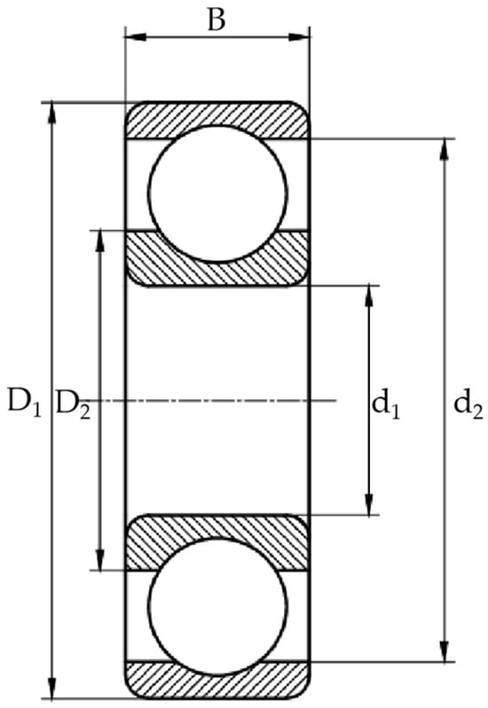
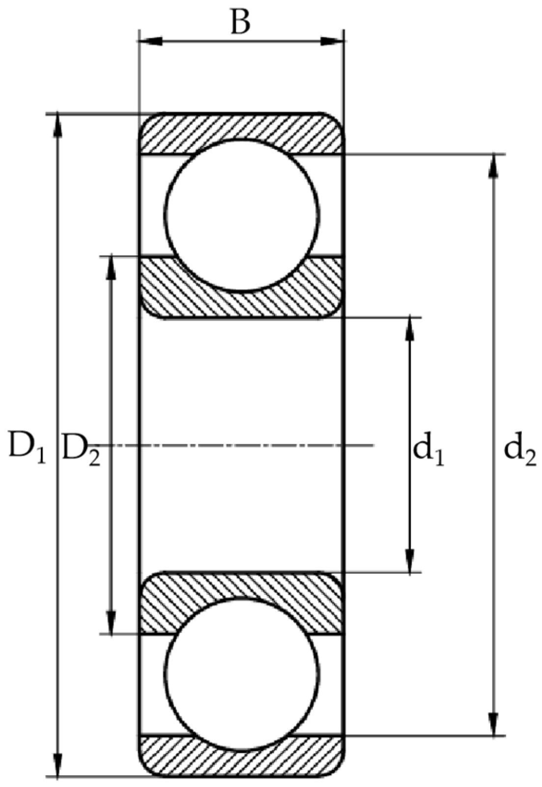
Owing to the hardness and brittleness of ceramics, the raceway in silicon nitride (Si3N4) ceramic ball bearings is generally more susceptible to damage than the balls during service. However, defects can shift the dominant failure location; when a defect is present in a ball, crack initiation is more likely to occur within the ball. During rolling contact with the raceway, the balls are subjected to high contact pressures. In defect-free bearings, sustained cyclic loading often leads to raceway surface spalling and the accumulation of internal microcracks. Once initiated, these cracks can propagate rapidly and coalesce, eventually resulting in raceway fracture and bearing failure. The presence of crack defects markedly reduces the compressive load-bearing capacity and service life of ceramic bearings. In this study, discrete element modeling is employed to analyze cracked ceramic bearings, and the associated mechanical calculation procedures are described in detail. A schematic diagram of silicon nitride ceramic bearings is shown in Figure 1.
Figure 1.
Schematic Diagram of Silicon Nitride Ceramic Bearings: D1 is the outer diameter, D2 is the inner diameter, B is the width, d1 is the inner ring shoulder diameter, and d2 is the outer ring shoulder diameter.
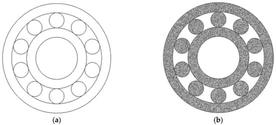
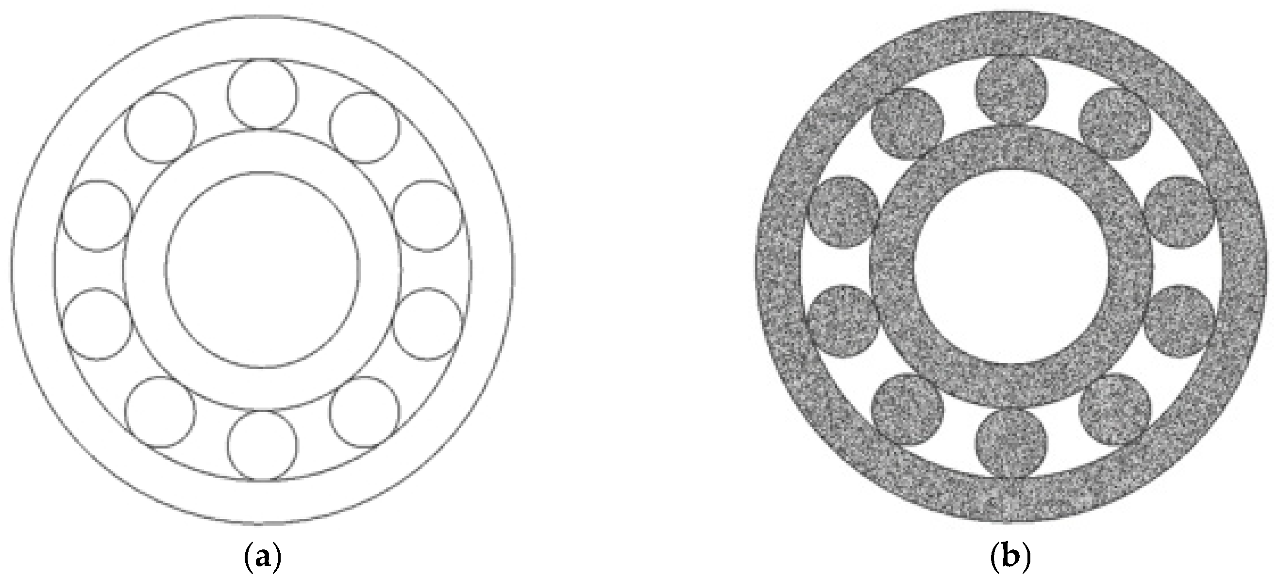
Constructing simple models in PFC2D is relatively straightforward because Particle Flow Code (PFC) supports direct geometry definition and particle generation. Standard tests, such as uniaxial compression of cylindrical specimens and Brazilian splitting tests on discs, can be implemented readily. However, for geometrically complex models, the built-in PFC2D tools are often insufficient—particularly for irregular wall boundaries, which are difficult to define using the native utilities alone. To overcome this limitation, the wall boundaries were constructed in AutoCAD (Version 2021). The resulting geometry was exported as a DXF file and imported into PFC, where particles were generated within the enclosed boundaries with a random spatial distribution. This workflow substantially reduces modeling complexity and improves reproducibility for irregular geometries. Using the workflow described above, a simplified silicon nitride (Si3N4) ceramic bearing model was established. The model parameters were: outer diameter 26 mm, inner diameter 10 mm, width 8 mm, inner ring shoulder diameter 14.8 mm, outer ring shoulder diameter 22.6 mm. The resulting model is shown in Figure 2.
Figure 2.
DEM ceramic bearing model: (a) Bearing Profile Wall. (b) Ceramic Bearing Particle Model.
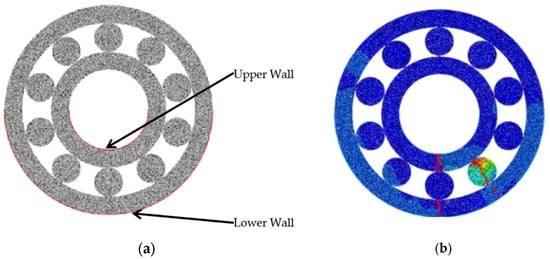
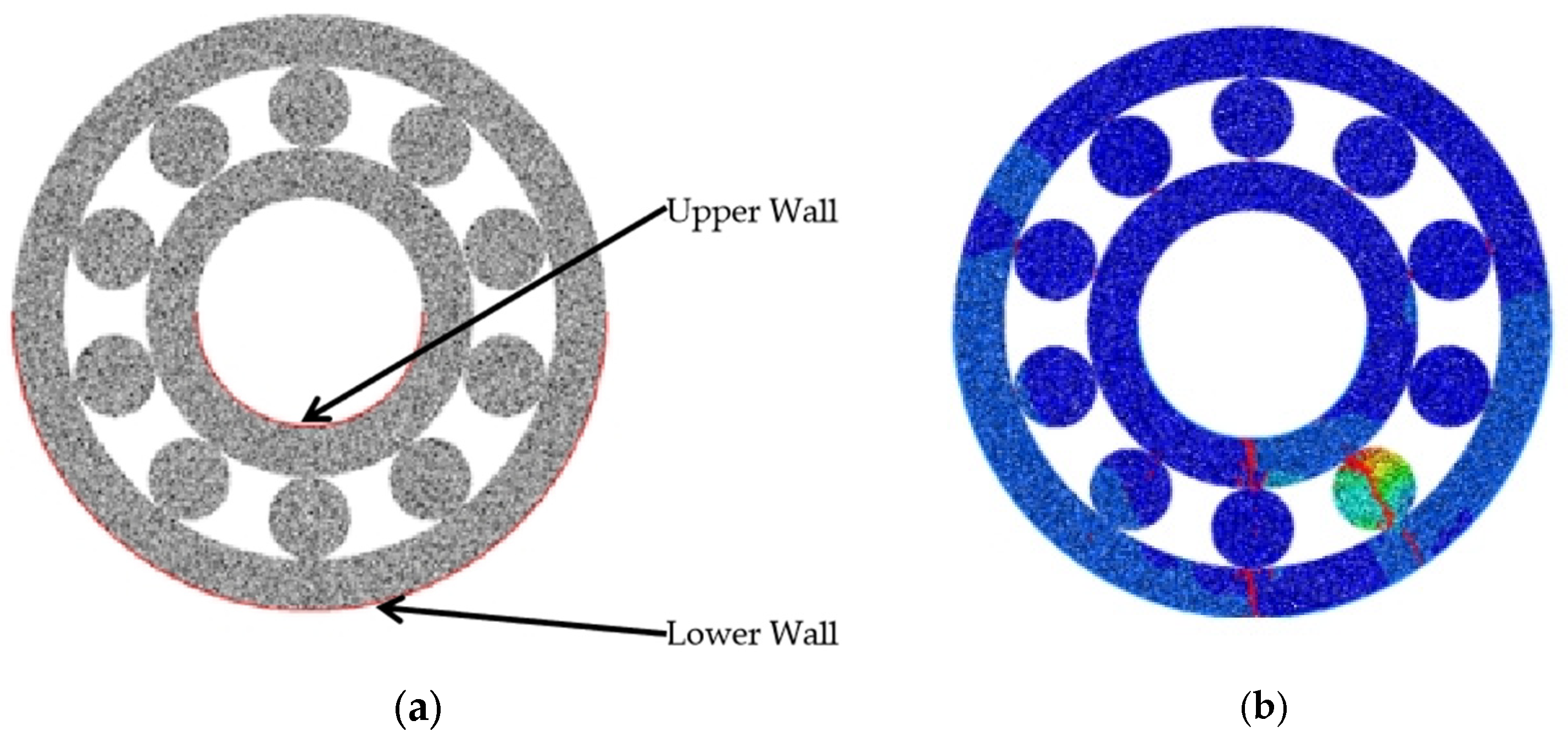
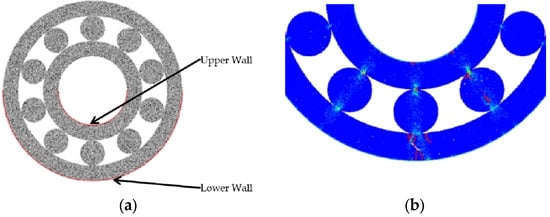
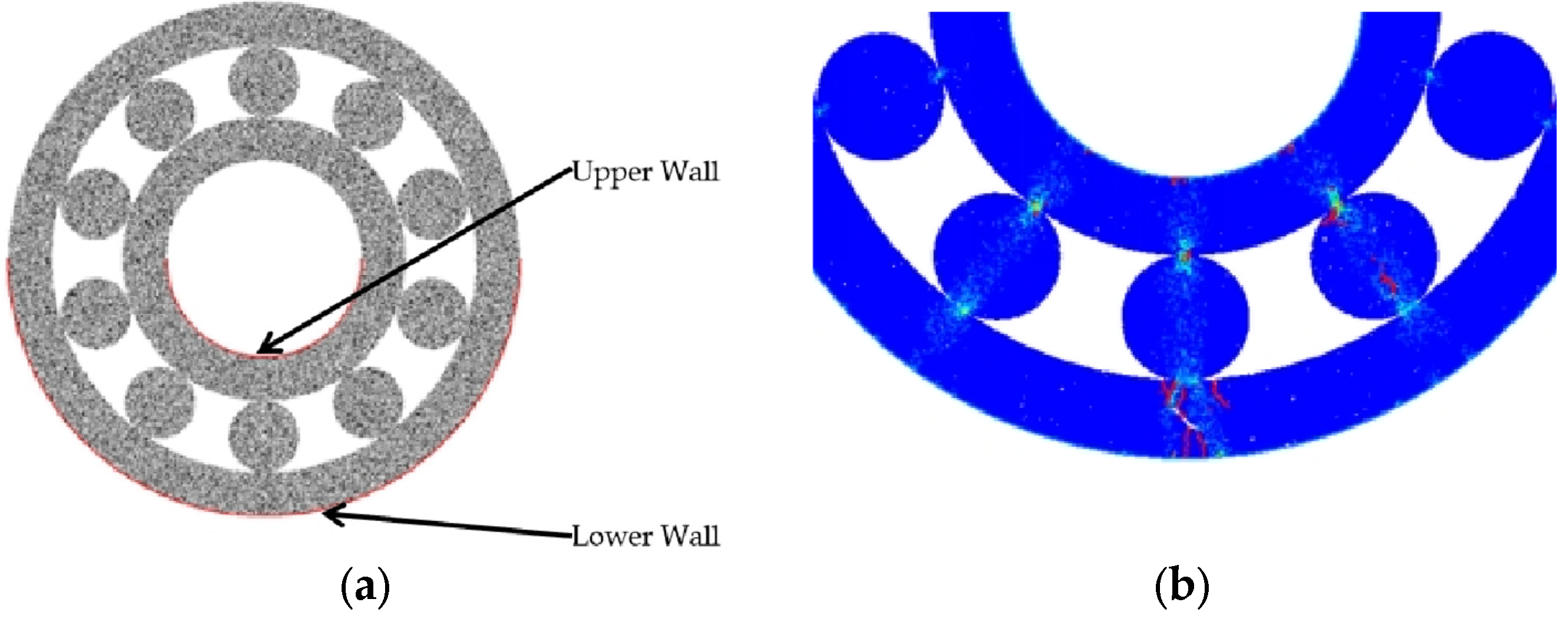
To reproduce the bearing’s compressive loading conditions in service, loading walls were generated to conform to both the inner and outer rings, as shown in Figure 3. The walls applied a displacement-controlled load in the negative Y direction. In PFC, the walls are defined as rigid boundaries with effectively infinite stiffness. This assumption prevents wall deformation during loading and improves the stability of the boundary conditions. In PFC, the walls are defined as rigid boundaries. This simplification is standard in DEM simulations focused on the material’s failure mechanism, as it ensures that the simulated response is dominated by the specimen itself rather than by boundary compliance. In the context of our study—which models a quasi-static overload scenario—the steel shaft and housing that constrain a real bearing undergo only minimal elastic deformation. This deformation is negligible compared to the displacements involved in the brittle fracture of the silicon nitride component. The rigid-wall assumption therefore provides a justified and stable numerical framework for isolating the effects of internal crack geometry on compressive failure, which is the primary objective of this analysis [26]. The loading rate is a critical parameter in the simulations. An overly slow rate reduces dynamic impact effects but substantially increases the computational cost. Conversely, an overly fast rate can introduce strong inertial/impact effects, degrading the accuracy of the results. Therefore, an appropriate loading rate must be selected to balance accuracy and efficiency. Accordingly, a loading rate of 0.01 m/s was adopted by moving the upper and lower walls vertically toward each other at a constant velocity. The discrete element simulations employed a loading rate of 0.01 m/s. This rate was selected as a practical compromise to ensure computationally feasible simulations while aiming to approximate quasi-static loading conditions. This loading rate was selected to approximate quasi-static conditions. Simulations were monitored to ensure that the ratio of kinetic energy to strain energy remained below 1 × 10⁻³, and a rate-sensitivity check confirmed that peak strength and fracture patterns varied by less than 2% when the rate was halved or doubled. Thus, inertial effects are negligible for the presented failure analysis. During the simulation, the stress response was monitored continuously. The simulation was terminated when the measured stress dropped below 70% of the peak value, which was adopted as a pragmatic failure criterion. This threshold is justified for brittle silicon nitride as it captures the characteristic, rapid loss of load capacity following major crack propagation—a point where the bearing would be considered functionally failed in an overload scenario (e.g., proof-loading). Moreover, our key findings regarding the weakening effects of crack angle and length were verified to be robust and not sensitive to the specific choice of this threshold (e.g., 60% or 80%). This criterion consistently marked the onset of macroscopic fracture and concluded the simulation.
Figure 3.
Loading mode of the ceramic bearing: (a) DEM Ceramic Bearing Particle Model Loading Method Demonstration. (b) Demonstration of Ceramic Bearing Load Configurations. different colours represent varying degrees of stress, localised increases in stress will cause a change in colour. the red line indicates crack propagation.
It is crucial to note that this is a two-dimensional (2D) simulation employing plane-strain assumptions, with an effective out-of-plane thickness set equal to the bearing width (10 mm). All forces measured from walls or particle contacts are converted to stresses (e.g., the reported GPa values) by dividing by the corresponding contact area, where the area is calculated as the product of the in-plane contact length and this nominal thickness. This approach provides a consistent basis for comparing the simulated compressive strength with experimental data, and is justified since the primary focus is on investigating the in-plane crack initiation and propagation mechanisms governed by the pre-existing flaw geometry.
2.4. Mechanical Calculation Methods for Silicon Nitride Ceramic Bearings
2.4.1. Principles of Stress–Strain Calculation
Before establishing a discrete element model, selecting an appropriate connection model is equally crucial. Parallel bonding models and straight joint models exhibit significant differences in particle suppression, and different connection models substantially impact the accuracy of experimental data. Silicon nitride ceramic materials will primarily be used for uniaxial compression tests, Brazilian splitting tests, and other similar procedures. During uniaxial compression, pressure can be monitored in real time via sensors, and results are obtained through stress calculation formulas. The stress calculation formula is as shown in Equation (3).
In this equation, σ represents stress, A denotes contact area, A = L × t, t is the nominal thickness, and F denotes contact force. the contact area A in Equation (3) is calculated as the product of the in-plane contact length and the nominal out-of-plane thickness of 10 mm, consistent with the plane-strain assumption introduced in Section 2.3.
The strain calculation formula is given by Equation (4).
In this equation, ε represents strain, ∆Y denotes the change in length of the specimen in the Y direction, and H denotes the initial length of the specimen.
To analyze localized stress fields within the bearing, the average stress tensor within a specified measurement circle is computed using PFC2D’s built-in function. In 2D, this provides the 2D stress tensor (force per unit length). For consistency with the reported macroscopic stresses, the components of this tensor are also converted to 3D-equivalent stress by dividing by the nominal thickness t.
The contact force between particles can be calculated using the Hertz contact model, as expressed in Equation (5).
In this equation, k represents the elastic modulus, and δ denotes the overlap (or relative displacement) between the particles, which is calculated directly at each timestep in the DEM simulation based on particle positions and contact detection.
When studying contact stresses, there are primarily two methods for obtaining stress values: directly measuring stresses from the contact wall or calculating average stresses. As a particle simulation method based on the discrete element method (DEM), PFC’s stress calculation is closely tied to the specific problem and model. In practical simulations, appropriate methods and formulas must be selected according to the problem characteristics. When measuring stress distribution in rolling balls, given the continuous nature of stress and the discrete nature of particles, it is insufficient to study only the contact stress between particles. Instead, a large number of measurement circles containing 50–80 particles must be arranged within the rolling ball to study the average contact stress between particles, as shown in Equation (6).
In this equation, V represents the volume of the measurement region, Nc denotes the number of all contacts within this region, denotes the contact vector for contact c, If both particles are within the measurement circle, the branch vector is typically taken as the vector between the centers of the two particles , If only one particle lies within the measurement circle (e.g., particle A), the branch vector is typically taken as the vector from the center of that particle to the contact point , denotes the force transmitted through contact c.
2.4.2. Calculation Methods for Elastic Modulus
When an object is subjected to external forces, it undergoes elastic deformation. Under simple uniaxial stress conditions, the elastic modulus can be directly calculated by dividing the stress by the strain in that direction. During the elastic deformation stage, stress is proportional to strain, adhering to Hooke’s law. This proportionality constant is the elastic modulus, an inherent property of materials encompassing Young’s modulus, shear modulus, and bulk modulus collectively.
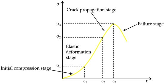
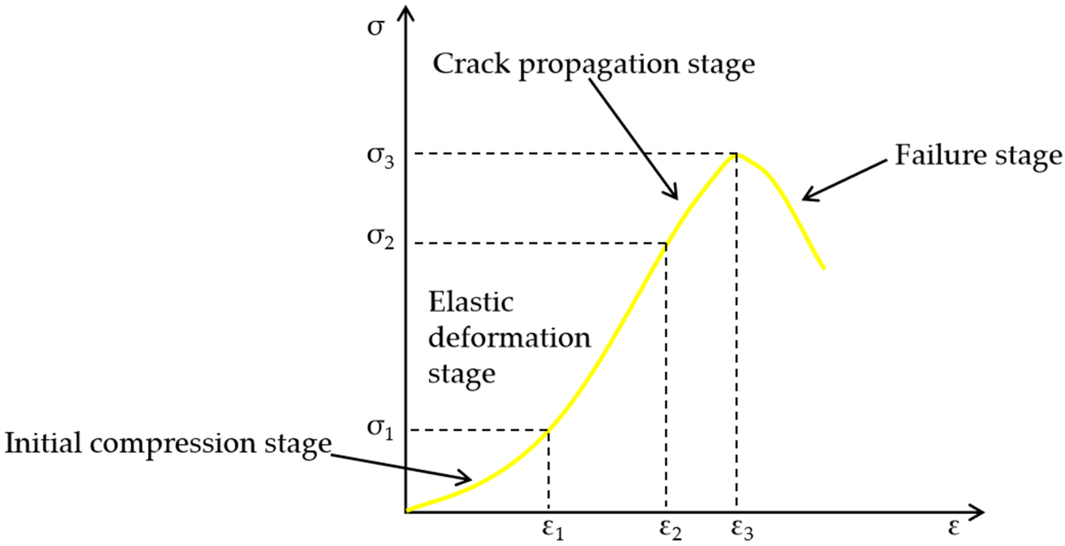
Taking silicon nitride ceramics as an example, their compressive deformation undergoes four stages: initial compression, elastic deformation, crack propagation, and failure, as shown in Figure 4. The failure process of hard brittle materials is extremely rapid, with stress rapidly released and decreasing from crack initiation to failure. During the elastic deformation stage, the slope of the stress–strain curve represents Young’s modulus, as expressed in Equation (7).
Figure 4.
Schematic diagram of the four stages of the compression process.
In this equation, E represents Young’s Modulus.
3. Experimental Results
3.1. Force Calibration Experiment
DEM micro-parameter calibration is typically performed by matching numerical responses to experimental results from uniaxial compression, three-point bending, and Brazilian splitting tests. In practice, trial-and-error is widely used to identify suitable DEM parameters by iteratively adjusting inputs until the simulated macroscopic response agrees with the experiment. The objective is to determine micro-parameters that reproduce target macroscopic properties (e.g., strength and Young’s modulus), thereby establishing a DEM model for silicon nitride (Si3N4) ceramic bearings.
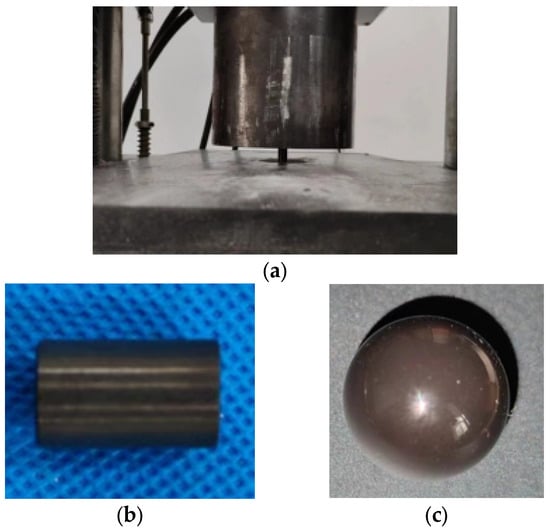
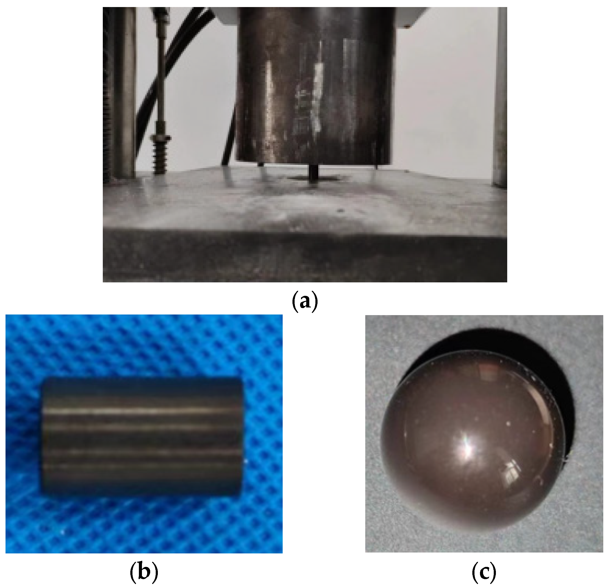
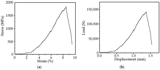
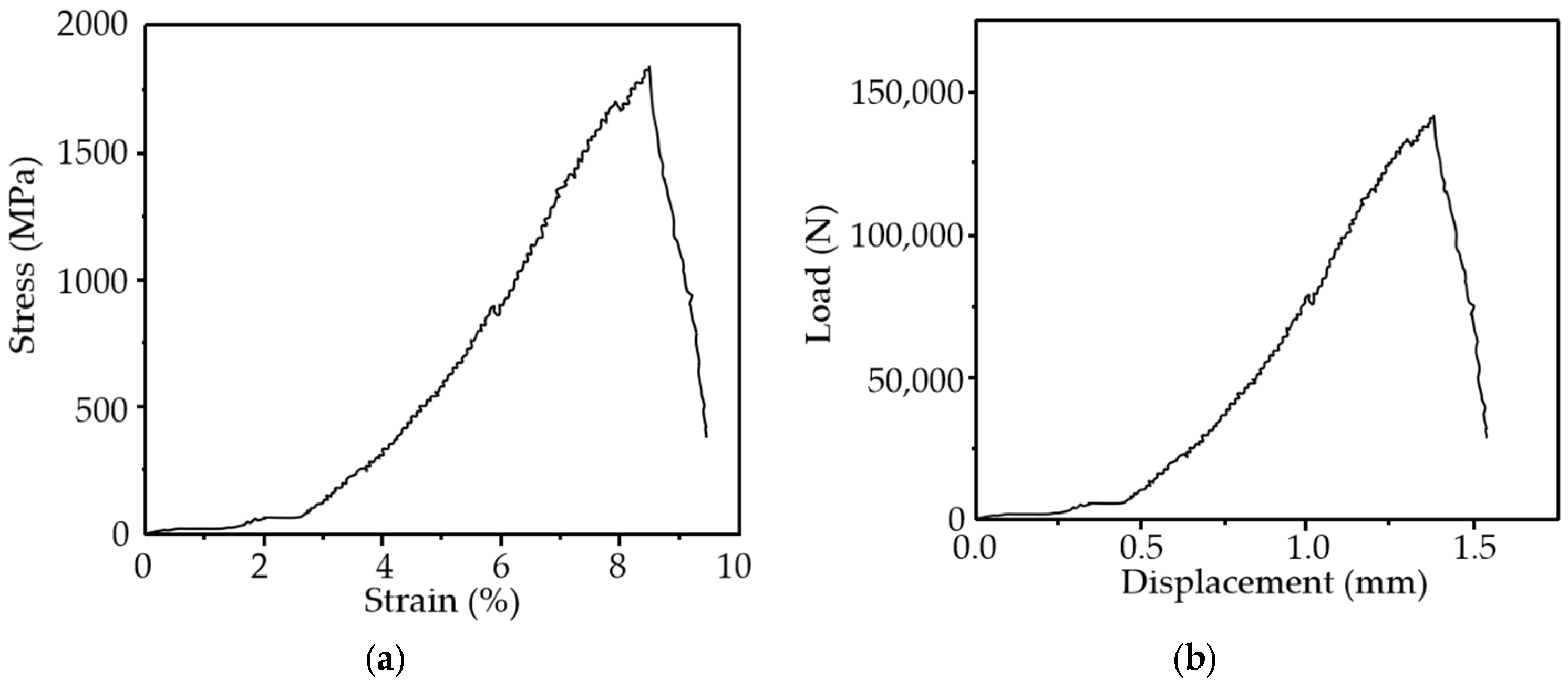
The DEM model was implemented in PFC2D, and calibration started with experimentally measured mechanical properties of Si3N4 ceramics. Mechanical tests were conducted using universal testing machines (INSTRON 5982/8872, CMT4104, and RGM-6300; Scientific Compass). The specimens included cylinders (10 mm × 20 mm) and balls with a radius of 10 mm, as shown in Figure 5. The target properties were obtained from uniaxial compression and Brazilian splitting tests conducted at a loading rate of 0.5 mm/min. During loading, the fracture was characterized by abrupt failure accompanied by random fragmentation. The DEM micro-parameters were finalized via trial-and-error to closely reproduce the measured macroscopic response. The test results and mechanical property curves are shown in Figure 6.
Figure 5.
Experimental Determination of Mechanical Properties of Silicon Nitride and Related Materials: (a) Experimental Demonstration Diagram. (b) Cylindrical model measuring 10 mm × 20 mm. (c) Rolling element with a radius of 10 mm.
Figure 6.
Mechanical characteristic curve: (a) Stress–strain Curve. (b) Displacement-Load Curve.
The accuracy of this calibration is quantified in Table 2, which compares the DEM-predicted macroscopic properties with the experimental targets. The low relative errors confirm that the calibrated model reliably captures the mechanical behavior of Si3N4.
Table 2.
Calibration validation: comparison between experimental and DEM-simulated macroscopic properties.
3.2. Precast Crack
In PFC simulations, three approaches are commonly used to pre-fabricate cracks: removing inter-particle bonds, using a discrete fracture network (DFN) to insert joint planes, and deleting particles within prescribed regions. Among these, particle deletion is the simplest and most direct method: particles are removed from the target location according to the prescribed crack orientation, length, and aperture (or thickness). Compared with DFN-generated flaws, cracks produced by particle deletion more closely resemble experimentally introduced and naturally occurring cracks. Therefore, particle deletion is adopted in this work as the primary crack pre-fabrication method.
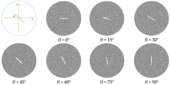
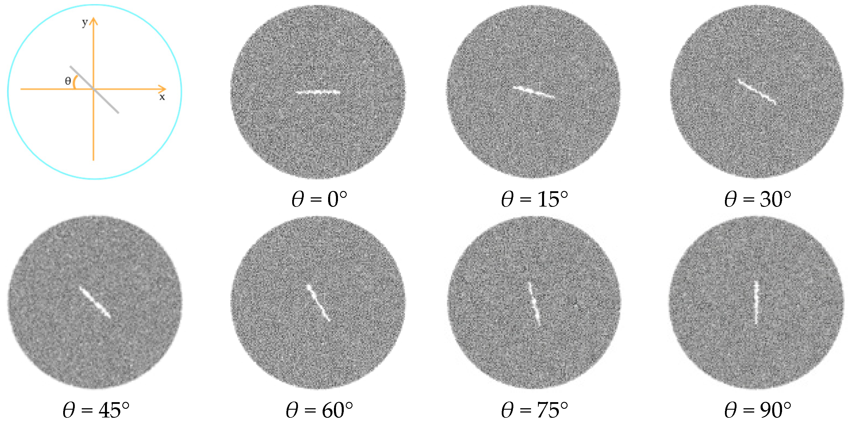
For the raceway and ball simulations, cracks with different inclination angles were prefabricated. The crack aperture was minimized to be close to the particle diameter, so as to better approximate realistic crack dimensions. Taking the Si3N4 bearing ball as an example, a central crack with an aperture of 6 10−2 mm and a length L = 0.8 mm was first introduced in Figure 7. The crack inclination angle θ was then varied from 0° to 90° in 15° increments, yielding seven crack configurations. For both ball and raceway cracks, a constant crack aperture of 6 10−2 mm (approximately equal to the particle diameter) was used in all simulations to realistically approximate a natural crack. The crack length (L) and inclination angle (θ) were then varied as the key geometric parameters.
Figure 7.
Ball prefabrication cracks at different angles. Grey indicates particulate matter, while white denotes the crack length.
3.3. Mechanical Properties and Failure Mechanisms of Ceramic Bearings with Crack Defects at Different Inclination Angles
A discrete element model of the ceramic bearing was developed in PFC2D, and numerical compression–splitting loading tests were subsequently performed. Owing to the bearing’s complex geometry, the contact loading can be approximated as a combination of uniaxial compression and splitting actions. To better reproduce realistic contact conditions, the upper and lower loading platens were modified to match the bearing geometry more closely. Specifically, semicircular wall elements were generated to conform to the inner and outer rings, as shown in Figure 8. A displacement-controlled load was then applied in the Y direction by moving the upper and lower walls at a constant rate of 0.01 m/s. The simulation was terminated when the measured stress decreased to below 70% of the peak value.
Figure 8.
Discrete element compression experiment of a ceramic bearing. (a) DEM Ceramic Bearing Particle Model Loading Method Demonstration. (b) Discrete Element Demonstration of Ceramic Bearings, different colors represent varying degrees of stress, localized increases in stress will cause a change in color. the red line indicates crack propagation.
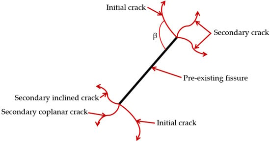
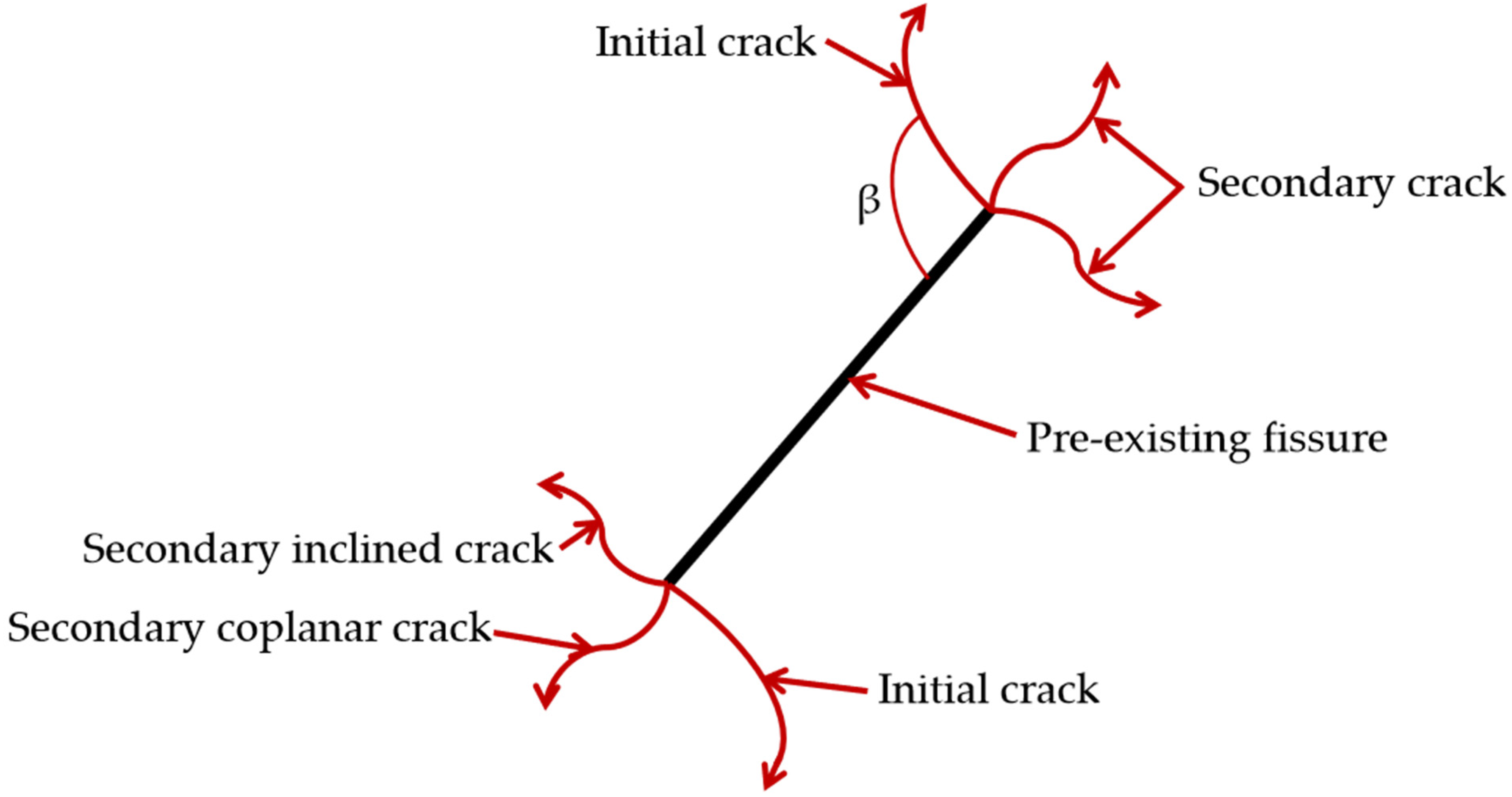
In the simulations, the load-induced response of ceramic bearings can be divided into three stages: an elastic stage, a crack-propagation stage, and a final fracture stage. In the elastic stage, the stress remains below the elastic limit and increases approximately linearly with loading. Once the stress reaches the crack-initiation threshold, damage initiates at intrinsic defects, typically as crack growth from existing crack tips. With further loading, cracks propagate and coalesce until they traverse the ball, leading to catastrophic failure of the bearing. For hard, brittle materials containing a single dominant defect, failure mechanisms are diverse and can be classified as tensile failure, mixed tensile–shear failure, mixed tensile–cleavage–slip failure, cleavage–slip failure, and cleavage failure. Under uniaxial compression, crack development is mainly observed in three forms—primary cracks, secondary coplanar cracks, and secondary inclined cracks—as shown in Figure 9.
Figure 9.
Common crack growth types.
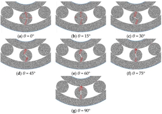
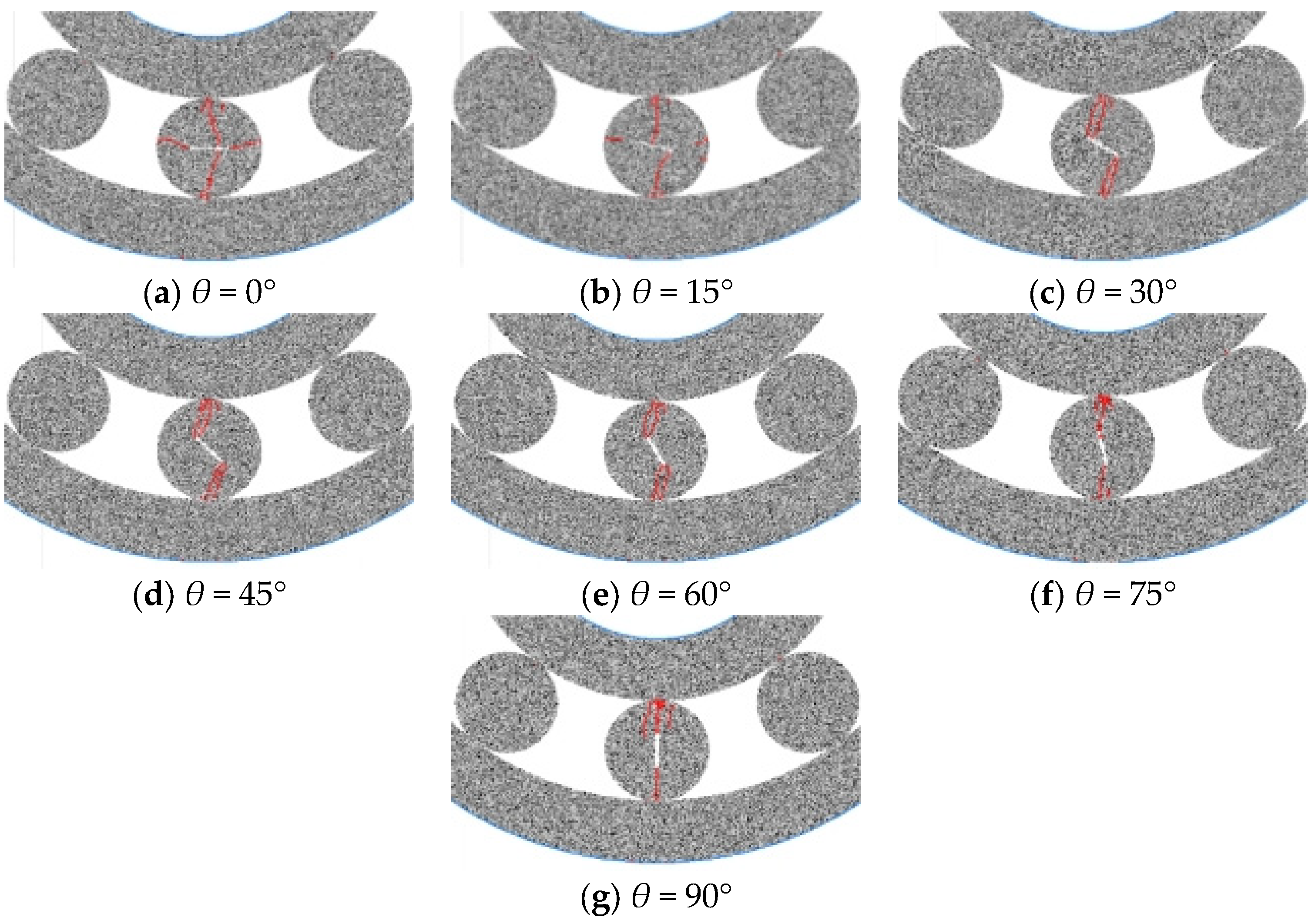
Figure 10 shows the compression-test results of the discrete element model for a ceramic bearing ball containing a prefabricated crack with inclination angles of 0°, 15°, 30°, 45°, 60°, 75°, and 90°. The cracks emanating from the pre-crack tip are consistent with prior findings, exhibiting an inclined trajectory and propagating in the opposite direction. At a defect inclination angle of 0°, shear cracks preferentially initiate near the defect center in both the numerical simulations and laboratory tests. As the inclination angle increases, the crack initiation site gradually shifts toward the defect tip and reaches the tip at 45°. Meanwhile, the crack initiation angle β increases progressively. Overall, these trends agree well with previous numerical results reported for brittle material.
Figure 10.
Crack growth of ball prefabrication at different angles and angles. The red line indicates crack propagation, while white represents the crack length.
The simulations further indicate that increasing the pre-existing crack inclination angle makes the nucleation of the primary crack more difficult. However, once initiated, the subsequent propagation-to-failure process becomes markedly faster. This can be explained by fracture mechanics principles. At higher inclination angles, the crack plane is more aligned with the maximum shear stress direction, but the driving force (Mode I stress intensity factor) for crack initiation may be reduced due to a less favorable orientation relative to the tensile stress field. This leads to a higher initiation stress threshold. However, once initiated, the crack can quickly re-orient or interact with the shear field, accessing a more efficient propagation path and leading to rapid failure). Previous studies suggest that secondary cracks are typically driven by shear stresses. As shown in Figure 10, the secondary cracks resemble the primary crack in morphology, while propagating in the opposite inclined direction.
Specifically, Figure 10a,b correspond to tensile–shear cracks. These cracks initiate either at the defect tip or at a short distance away from it. Under shear stress, as the crack approaches the specimen boundary, its trajectory gradually deflects and propagates along a direction inclined relative to the radial load. The corresponding failure mode is mixed tensile–shear coupled with splitting. Figure 10c–f correspond to tensile wing cracks. These cracks display a wing-like morphology and propagate toward the specimen boundary either approximately parallel to the radial load or with a rotation toward the loading direction, depending on the initial orientation. The associated failure mode is predominantly tensile. Figure 10g correspond to tensile vertical cracks. These cracks propagate perpendicular to the bearing axial direction and extend along the loading direction, and the failure mode is tensile splitting.
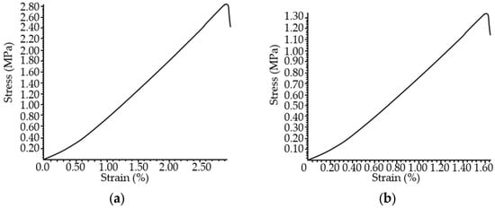
Numerous experiments and existing studies indicate that internal defects in workpieces significantly affect their mechanical properties [8,11]. Among these, the impact of pre-cracked defects on the compressive strength of ceramic bearings is particularly pronounced, substantially altering both their crack initiation stress and peak stress. Compared to the compression test results of ceramic bearings without pre-cracking, those with 90° inclined pre-cracking exhibited both initiation stress and peak stress values approximately one-third of those without pre-cracking.
Figure 11 displays the stress–strain curves of ceramic bearings. During the elastic stage, stress and strain exhibit a linear growth relationship. When crack initiation occurs, the curve shows slight fluctuations. As the crack propagates through the entire specimen, the curve exhibits severe fluctuations, and stress drops sharply, indicating bearing failure and damage.
Figure 11.
Stress–strain Curve: (a) Stress–strain Curve of Non-Precracked Ceramic Bearings. (b) 90° Ball Pre-Cracked Stress–strain Curve.
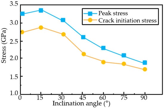
Figure 12 shows that between 0° and 15°, initial cracking and peak stress briefly increase, possibly because small-angle cracks initially alleviate localized stress concentration. Beyond 15°, both stress values continuously decrease, with high angles causing greater load-bearing reduction. For instance, increasing the inclination angle from 15° to 75° reduces peak stress by 42%. As the inclination angle increases, the difference between cracking initiation and peak stress gradually diminishes, accelerating crack propagation. Microscopically, high angles readily induce stress concentration. Beyond 45°, crack propagation becomes straighter with fewer branches, further accelerating the process.
Figure 12.
Crack stress relationship of prefabricated ball with different inclination angles.
The observed non-monotonic trend (Figure 12) arises from competing micro-scale mechanisms. The initial strength increase (0–15°) stems from a transition from low-energy shear initiation to a higher-energy mixed tensile-shear mode at the crack tip. Beyond 15°, alignment with the maximum shear plane eases initiation, while promoting unstable tensile wing crack growth, causing peak strength to decline sharply. This differs fundamentally from raceway cracks, where strength minimizes at 45° (Section 3.4) under a balanced compression-shear state. The diminishing gap between initiation and peak stress confirms the accelerated failure progression at higher angles.
3.4. Simulated Crack Growth in the Raceway
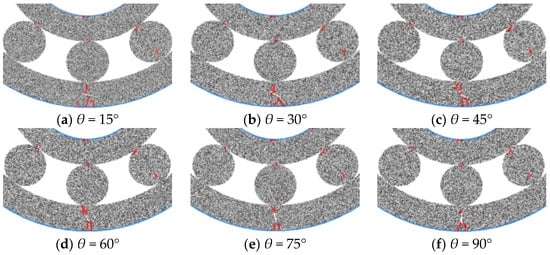
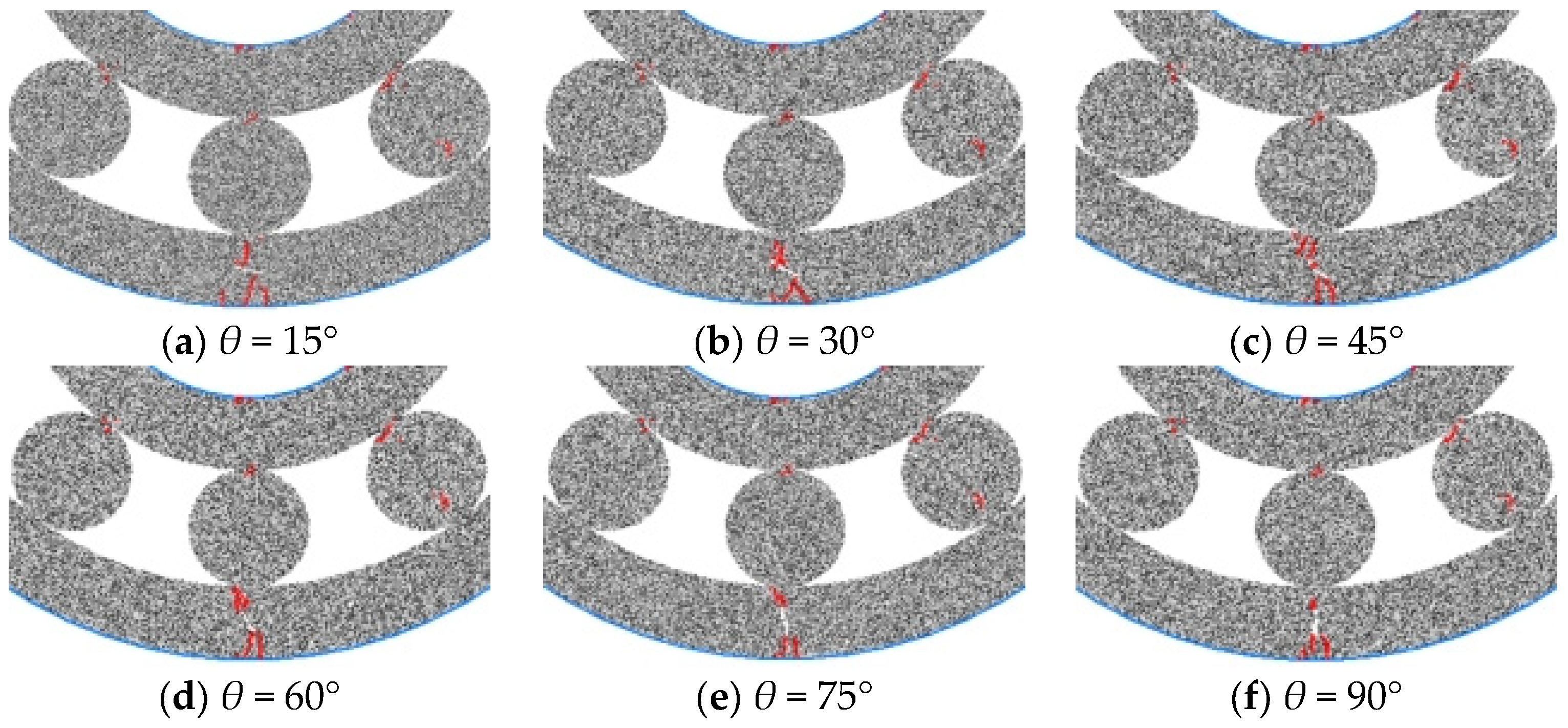
As shown in Figure 13, because the balls contain no prefabricated defects, crack initiation occurs at the pre-existing crack in the raceway. In contrast to the ball-dominated splitting response, the raceway experiences a coupled splitting–compression loading state, resulting in failure modes that involve tensile cracking as well as mixed tensile–shear behavior.
Figure 13.
Prefabricated crack growth of six groups of raceways with different inclination angles. The red line indicates crack propagation, while white represents the crack length.
At crack inclinations of 15–30°, the raceway fails primarily in shear: wing-shaped shear cracks initiate at both crack ends and evolve into two inclined through-cracks that cut across the raceway. Secondary cracking occurs mainly after penetration and is largely driven by tensile stress. At 45–60°, a mixed tensile–shear mode is observed. Shear cracks first develop at the crack ends and propagate obliquely; meanwhile, near-vertical secondary cracks initiate earlier, extend rapidly, and together with the primary cracks lead to complete raceway penetration and bearing failure. At 75–90°, crack growth initiates from the crack tip and, after a short extension, secondary cracks nucleate adjacent to (rather than exactly at) the tip and propagate approximately parallel to the loading direction. In this regime, failure is governed by secondary-crack coalescence, exhibiting an overall compressive–shear dominated characteristic.
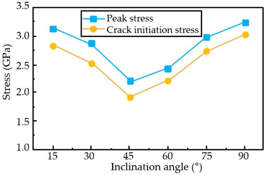
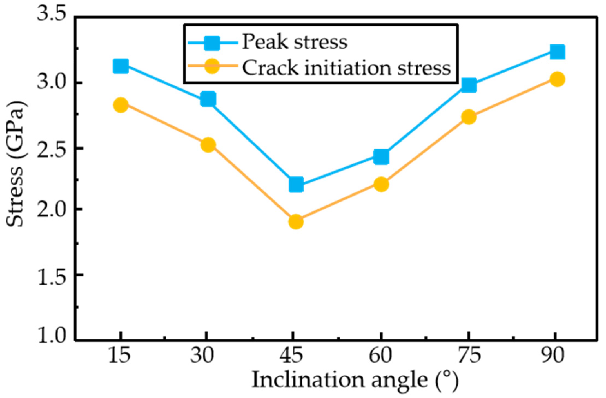
Unlike prefabricated defects in ball bearings, the compressive strength of prefabricated cracks in the outer ring of this bearing exhibits distinct behavior compared to ball defects. It first decreases and then increases as the crack angle increases. The compressive strength corresponding to different crack inclination angles is shown in Figure 14.
Figure 14.
Crack stress relationship of the prefabricated raceway crack with different inclination angles.
Figure 14 clearly shows that the compressive strength of the ceramic bearing reaches its minimum at a crack angle of 45° and its maximum at 90°. When the crack angle is less than 45°, compressive strength increases with angle, and the decay rate gradually rises. At 45°, compressive strength drops to its lowest point. Thereafter, compressive strength begins to rise, with the growth rate first increasing and then decreasing. At 90°, compressive strength reaches its maximum.
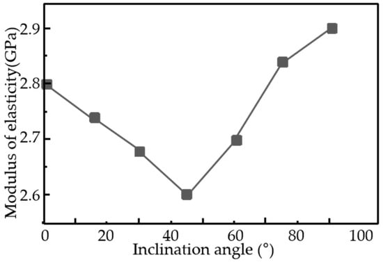
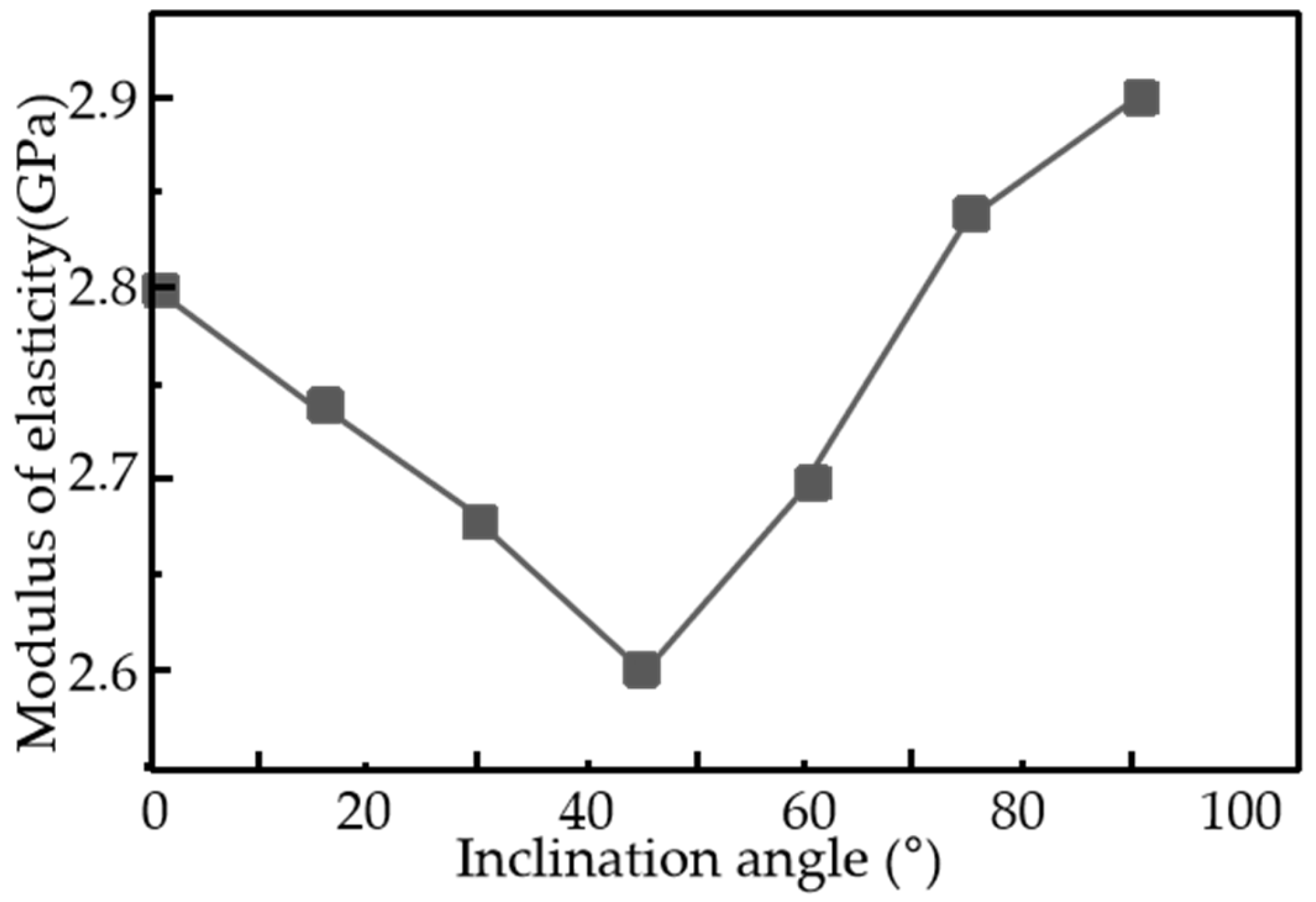
Regardless of how the crack inclination angle changes, defects reduce the elastic modulus of silicon nitride ceramic bearings. As shown in Figure 15, the elastic modulus initially decreases with increasing crack inclination angle, reaching a minimum at 45°. It then begins to rise, reaching a maximum at 90°, though remaining below the elastic modulus of the intact specimen.
Figure 15.
Obliquity-elastic modulus relation.
The distinct minimum in compressive strength at a 45° crack inclination results from an optimal alignment for mixed-mode fracture. At this orientation, the resolved tensile and shear stress intensity factors at the crack tip are nearly equal, creating a synergistic effect that minimizes the energy required for crack propagation. This promotes the simultaneous and efficient initiation of both tensile and shear cracks, leading to the most severe strength degradation. In contrast, at shallower (e.g., 15°) or steeper (e.g., 90°) angles, the stress state becomes dominated by either shear or tensile components, respectively, which are less effective in driving a coupled failure. Furthermore, the 45° orientation maximizes the effective compliance of the raceway in the loading direction, correlating with the lowest measured effective elastic modulus.
3.5. Mechanical Properties and Failure Mechanisms of Ceramic Bearings with Crack Defects of Different Sizes
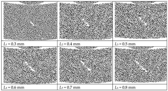
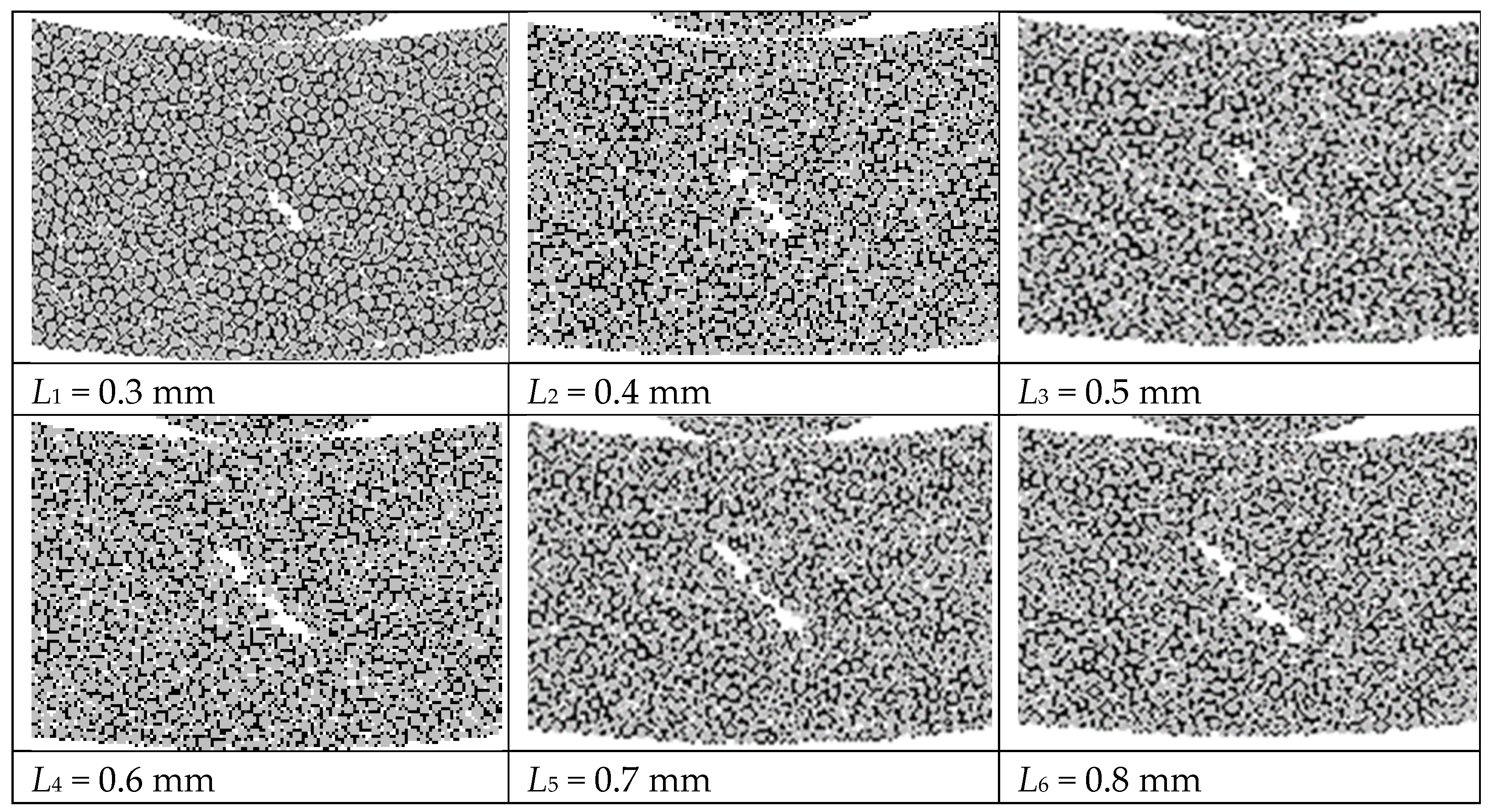
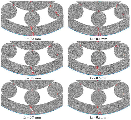
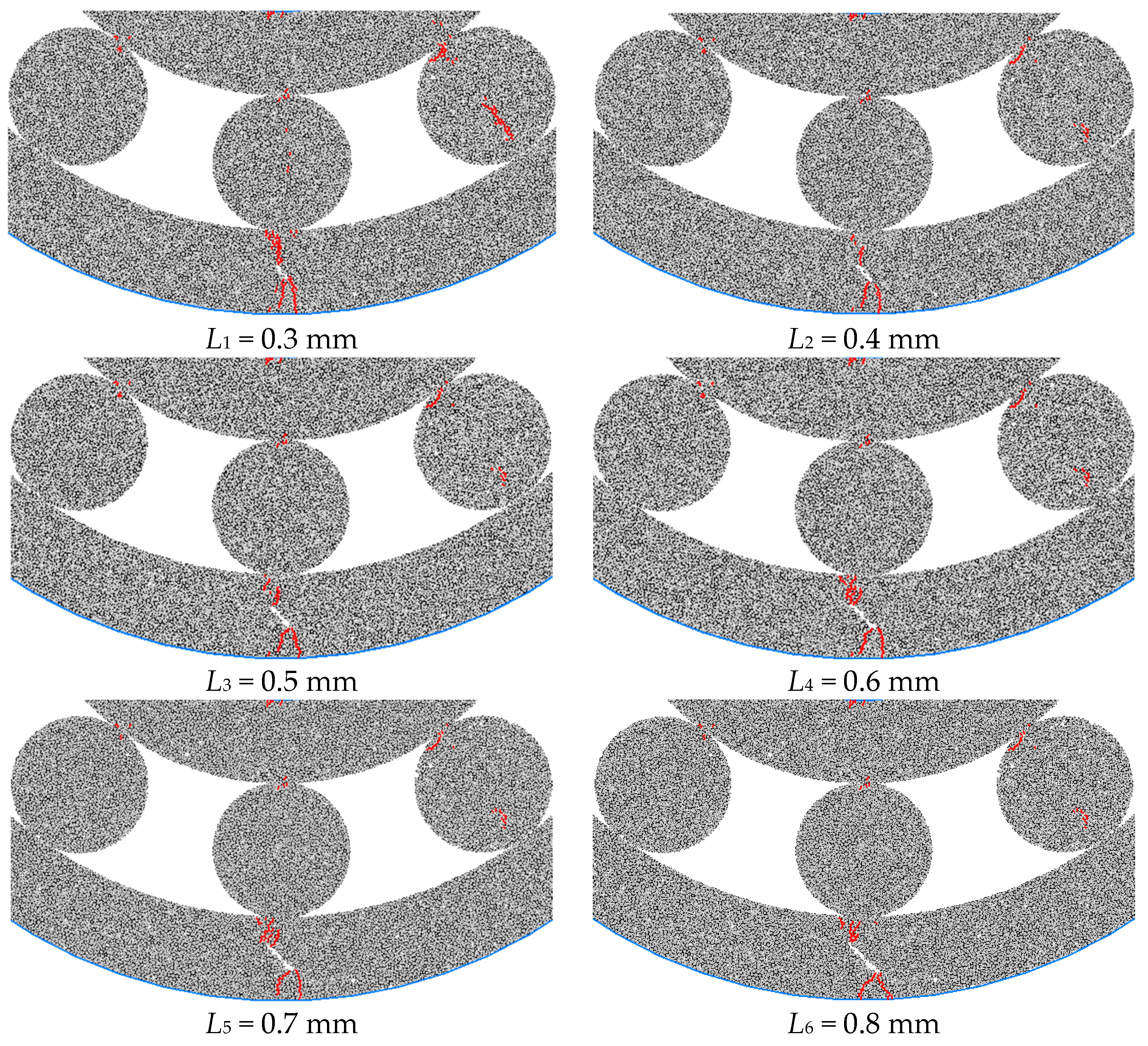
In the discrete element model of silicon nitride ceramic bearings, the size of pre-fabricated crack defects significantly influences the compressive strength and crack evolution. To relate crack dimensions to the bearing geometry, the crack length L was normalized by the raceway thickness (8 mm) and ball diameter. The tested crack lengths correspond to normalized lengths L/D Ball of ≈3.8%, 5.0%, 6.3%, 7.6%, 8.8%, and 10.1%, respectively. This study maintains a constant crack width while varying the pre-crack length, specifically at L = 0.3 mm, 0.4 mm, 0.5 mm, 0.6 mm, 0.7 mm, and 0.8 mm. The crack inclination angle is uniformly set at 45°, with the corresponding model illustrated in Figure 16.
Figure 16.
Six groups of raceway precast cracks of different lengths and sizes.
It is particularly important to note that the selection of the prefabricated crack length is critical. It must neither be too large nor too small, but must meet the requirements of actual defect dimensions. If the crack length is too small, the influence of the prefabricated defect on the research results will be negligible, and there may also be problems with incomplete deletion when simulating defect removal. If the crack length is too large, the research results obtained will not correspond to the actual situation, greatly reducing the research value.
The crack propagation characteristics of silicon nitride ceramic bearing raceways at different crack lengths are shown in Figure 17. Overall, larger pre-existing defects trigger earlier crack initiation, faster propagation, and more pronounced secondary cracking; in some cases, secondary cracks penetrate the raceway before the primary crack. When L < 0.3 mm, the crack-tip stress concentration is weak, and the early evolution near the upper end of the defect makes primary and secondary cracks difficult to distinguish, indicating a limited influence on crack growth and compressive strength. In contrast, when L > 0.3 mm, stress concentration—especially at the crack tip—becomes significant, strongly affecting both crack trajectories and mechanical response. With increasing L, the angle between the primary crack and secondary cracks generally increases.
Figure 17.
Crack growth of six groups of prefabricated defects of different lengths. The red line indicates crack propagation, while white represents the crack length.
Two representative propagation regimes can be identified. For L1, L2, and L3, Cracking typically initiates at the upper end of the pre-crack. After a short extension, a second primary crack forms at the lower end, and the two propagate in opposite directions. Secondary cracks then develop, and the lower secondary crack usually penetrates first, leading to failure. Notably, L1 exhibits more abrupt and complex growth than L2 and L3, consistent with rapid crack acceleration once a critical load is reached.
For L4, L5, and L6, the lower primary crack forms first while upper initiation lags; the lower primary crack may arrest, after which secondary cracks dominate and penetrate before the primary crack. On the upper side, secondary cracks may nucleate near the ball-contact side rather than directly at the pre-crack tip and then link up with the primary crack.
Across all lengths, failure is characterized by a tensile–shear mixed mode. The inner raceway, subjected to ball pressure, exhibited compression behavior similar to Brazilian splitting. while the outer side experienced loading from the wall, displaying a compression pattern similar to uniaxial compression. The stress types differed slightly. uniaxial compression was primarily compressive, whereas splitting was mainly tensile. This explains the significant difference in crack propagation directions above and below the pre-existing cracks.
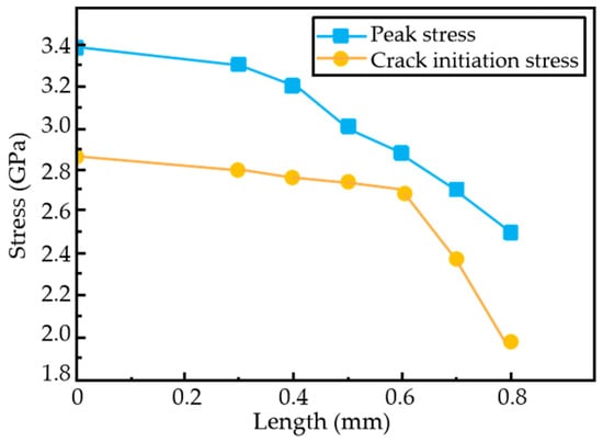
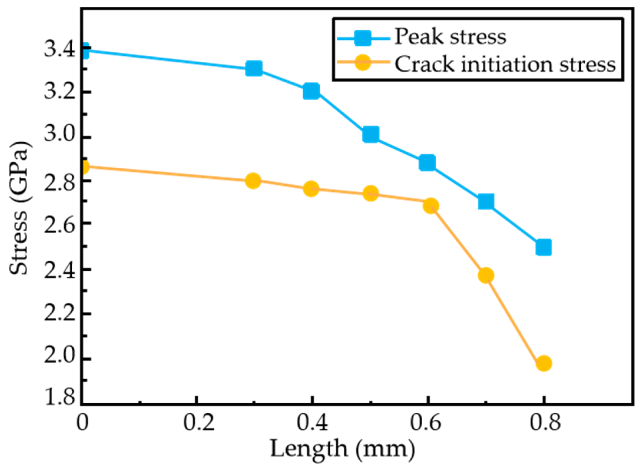
Existing evidence suggests that crack length has a stronger effect on the compressive strength of ceramic bearings than the crack inclination angle. Numerical simulations further show that increasing crack length markedly reduces both the crack-initiation stress and the peak compressive stress. As illustrated in Figure 18, when L < 0.3 mm, the influence on compressive strength is limited and the peak stress decreases only slightly; when L > 0.3 mm, the reduction in peak stress becomes much more pronounced, and with further increases in L, the peak stress drops at an accelerating rate. A similar threshold behavior is observed for crack-initiation stress: it decreases gradually for L < 0.6 mm but declines sharply once L > 0.6 mm.
Figure 18.
Prefabricated crack stress relationship of different raceway lengths.
Research reveals a correlation between crack dimensions and the compressive strength and service life of samples. Adjusting crack dimensions influences the mechanical properties and failure mechanisms of silicon nitride ceramic bearings. In-depth investigation of the relationship between dimensions and strength enables the screening of qualified products during sample manufacturing. Nondestructive testing can then be employed to determine whether ceramic bearings meet standards, thereby eliminating samples with defects exceeding critical thresholds.
The identified threshold lengths of 0.3 mm and 0.6 mm (Figure 18) demarcate transitions in the crack-size dominance regime. For cracks shorter than 0.3 mm, the stress intensity at the tip remains low, and their influence on global strength is marginal, resembling the failure of a near-intact structure. Beyond the 0.3 mm threshold, the stress intensity factor increases sufficiently to cause significant local damage, initiating a stable but progressively weakening crack growth phase. The second critical threshold at 0.6 mm signifies the onset of unstable fracture dynamics. At this length, the crack’s process zone begins to interact substantially with inherent micro-defects and the specimen boundaries, leading to a shift from isolated crack propagation to pervasive damage coalescence. This transition is marked by the abrupt drop in initiation stress, as the system’s energy release rate surpasses the critical value required for unstable propagation.
4. Conclusions and Future Work
4.1. Conclusions
This paper focuses on the influence of single prefabricated defects on the mechanical properties and failure mechanisms of silicon nitride ceramic bearings, with particular emphasis on the effects of crack inclination angle, position, and size on compressive strength. Analysis of the DEM simulation results yields the following conclusions:
- Influence of Pre-Fabricated Defects on the Mechanical Properties of Bearings with Cracked Balls. Pre-existing defects alter the compressive strength and effective Young’s modulus of ceramic bearings. When cracks are located on the ball, both the initial cracking stress and peak stress exhibit complex trends with crack inclination angle: a brief initial increase followed by a decrease, declining from 15°, briefly rising at 45°, and continuously decreasing beyond 60° as the angle increases, resulting in an overall reduction in compressive strength.
- Effect of Pre-existing Defects on Mechanical Properties of Bearings with Raceway Cracks. For defects in the raceway, both initial cracking stress and peak stress decrease, then increase with increasing crack inclination angle. Compressive strength reaches its minimum at 45° and its maximum at 90°. The effective Young’s modulus first increases (at 30°), then decreases (at 45°), reaching its lowest point at 45° before recovering but not exceeding the intact specimen value.
- Crack length significantly impacts compressive strength, which continuously decreases with increasing crack length. Below 0.3 mm, compressive strength declines gradually; beyond this threshold, the rate of decline accelerates. The cracking stress curve for initial cracks differs from the peak stress curve, showing a rapid and pronounced decrease when crack length exceeds 0.6 mm. These thresholds correspond to defect sizes that are both detectable by conventional NDT methods and critical for overload failure, providing quantitative guidance for accept/reject criteria in quality screening of ceramic bearings.
- Crack Evolution Characteristics and Failure Modes Pre-cracked raceways with different crack lengths exhibit similar failure modes and crack propagation patterns, differing only in the sequence of crack initiation. For smaller cracks (L1, L2, L3), initial cracking originates from the upper side of the crack, resulting in a failure pattern close to that of an intact specimen, resembling fragmentation. For larger cracks (L4, L5, L6), cracking initiates from the lower side. Under combined compressive and shear stresses, shear-initiated cracks form first, followed by secondary cracks. These secondary cracks initially traverse the raceway, and ultimately, both cracks connect, leading to ceramic bearing failure.
Furthermore, future research could delve into how different loading methods, like cyclic and impact loading, influence the mechanical properties and failure mechanisms of silicon nitride ceramic bearings with prefabricated cracks, as these methods alter stress distribution and crack propagation paths, enabling more accurate predictions of bearing service life and reliability. Meanwhile, a brief investigation into the effects of environmental factors such as temperature variations on pre-cracked ceramic bearings would also enhance our understanding of their real-world performance.
4.2. Future Work
To address these limitations and enhance the practical applicability of the proposed method, future work will focus on the following directions:
- Influence of Different Loading Conditions. Future studies will extend the framework to investigate how various service-relevant loading conditions—such as cyclic fatigue, impact, and non-proportional multiaxial loading—affect crack initiation and propagation in defective bearings. This will provide crucial insights for predicting performance under complex operational profiles.
- Simulation of Cyclic Fatigue Loading. Building on the above, a primary focus will be simulating true cyclic rolling contact to understand fatigue crack growth and spalling mechanisms, thereby bridging the gap towards predictive rolling contact fatigue life assessment.
- Integration of Environmental Factors. The model will be expanded to account for operational environments, particularly studying the coupled effects of temperature fluctuations and lubrication on defect sensitivity and failure modes.
Pursuing these research directions will transition the framework from fundamental analysis towards a practical tool for reliability assessment, ultimately supporting the design and qualification of ceramic bearings for demanding applications.
Author Contributions
Conceptualization, C.L. and X.G.; methodology, C.L. and X.G.; software, C.L. and X.C.; validation, X.C. and Z.Z.; formal analysis, X.C.; investigation, C.L.; resources, X.G.; data curation, C.L. and L.Y.; writing—original draft preparation, C.L.; writing—review and editing, X.G.; visualization, C.L., L.Y. and X.G.; supervision, X.G.; project administration, C.L. and X.G.; funding acquisition, X.G. All authors have read and agreed to the published version of the manuscript.
Funding
This work was supported by the Science Research Fund of the Department of Science and Technology of Liaoning Province, China (2025-MSLH-587). This work was sup-ported by the National Natural Science Foundation of China (52275119).
Institutional Review Board Statement
Not applicable.
Informed Consent Statement
Not applicable.
Data Availability Statement
The original contributions presented in this study are included in the article. Further inquiries can be directed to the corresponding author.
Conflicts of Interest
Author Xuedong Chen was employed by Yingkou Dongbang Environmental Science and Technology Co., Ltd. The remaining authors declare that the research was conducted in the absence of any commercial or financial relationships that could be construed as a potential conflict of interest.
References
- Wang, P.; Zhang, X. Experimental Study of the Service Performance of Full Ceramic Silicon Nitride Ball Bearings. Lubricants 2025, 13, 461. [Google Scholar] [CrossRef] [Scilit]
- Wang, Z.; Xiong, Z.; Wang, F.; Liao, W.; Farisi, Z.; Rao, G.; Hu, K. Centroid Growth Selective Clustering Method for Surface Defect Detection in Silicon Nitride Ceramic Bearing Rollers. Sci. Rep. 2025, 15, 29074. [Google Scholar] [CrossRef] [Scilit] [PubMed]
- Wang, Y.; Li, S.; Wei, C.; Liu, B.; Zhang, Y.; Lin, G.; Wang, K.; Zhao, J. Study on the Effect of Thermal Characteristics of Grease-Lubricated High-Speed Silicon Nitride Full Ceramic Ball Bearings in Motorized Spindles. Lubricants 2024, 12, 286. [Google Scholar] [CrossRef] [Scilit]
- Maeda, T.; Osada, T.; Ozaki, S. Reliability Evaluation Scheme for Ceramics Based on Defect Size Distribution Inversely Esti-mated from Standardized Tests. J. Am. Ceram. Soc. 2025, 108, e20660. [Google Scholar] [CrossRef] [Scilit]
- Zheng, J.; Li, H.; Hogan, J.D. Hybrid Finite-Discrete Element Modeling of the Mode I Tensile Response of an Alumina Ceramic. Modelling 2023, 4, 87–101. [Google Scholar] [CrossRef] [Scilit]
- Tian, X.; Birk, C.; Du, C.; Ooi, E.T. Automatic Micro-Scale Modelling and Evaluation of Effective Properties of Highly Porous Ceramic Matrix Materials Using the Scaled Boundary Finite Element Method. Comput. Methods Appl. Mech. Eng. 2024, 419, 116596. [Google Scholar] [CrossRef] [Scilit]
- Zhang, J.; Zhou, X. Fracture Process Zone (FPZ) in Quasi-Brittle Materials: Review and New Insights from Flawed Granite Subjected to Uniaxial Stress. Eng. Fract. Mech. 2022, 274, 108795. [Google Scholar] [CrossRef] [Scilit]
- Li, T.; Shi, H.; Bai, X.; Zhang, K.; Bin, G. Experimental Analysis and Modeling of Subsurface Cracks with Random Propagation for Ceramic Material on Rolling Contact Fatigue. Eng. Fail. Anal. 2024, 155, 107753. [Google Scholar] [CrossRef] [Scilit]
- Staudacher, M.; Lube, T.; Schwarzer-Fischer, E.; Abel, J.; Reichel, M.; Lorenz, N.; Gottlieb, L.; Long, S.; Fehleisen, F.; Scheithauer, U. Strength Limiting Defects in Additively Manufactured Ceramics. Open Ceram. 2025, 24, 100858. [Google Scholar] [CrossRef] [Scilit]
- Du, W.; Jin, S. Discrete Element Modelling of Cold Crushing Tests Considering Various Interface Property Distributions in Ordinary Refractory Ceramics. Materials 2022, 15, 7650. [Google Scholar] [CrossRef] [Scilit]
- Li, Y.; Wang, L.; Gao, H.; Zhang, J. Discrete element model for cracking in defective ceramics under uniaxial compression. Comput. Part. Mech. 2023, 11, 1565–1577. [Google Scholar] [CrossRef] [Scilit]
- Xie, A.Y.; Ding, X.; Chen, R.; Li, B.Q. Quantifying the Effect of Inter-Granular Interlock on Pre-Peak Micro- and Macro-Fracture Mechanisms in Rock-Like Specimens Using 3D Discrete Element Method Simulation. Powder Technol. 2025, 464, 121215. [Google Scholar] [CrossRef] [Scilit]
- Jiang, S.; Zhang, W.; Li, X.; Xu, Z.; Liu, J.; Liu, S. Discrete Element Simulation of Compression Failure Mechanism of SiC Ceramic Considering Collinear Flaws. J. Mech. Behav. Biomed. Mater. 2023, 142, 105849. [Google Scholar] [CrossRef] [Scilit] [PubMed]
- Zhang, Z.; Xu, J.; Zhu, Y.; Zhang, Z.; Zeng, W. Material Removal Mechanism of SiC Ceramic by Porous Diamond Grinding Wheel Using Discrete Element Simulation. Materials 2024, 17, 2688. [Google Scholar] [CrossRef] [Scilit]
- Wang, K.; Fu, X.J.; Wang, Y. PFC2D-Based Analysis of the Effect of the Axial Loading Rate on the Mechanical Properties of Backfill. Adv. Mater. Sci. Eng. 2023, 2023, 4398285. [Google Scholar] [CrossRef] [Scilit]
- Ghazvinian, A.; Sarfarazi, V.; Schubert, W.; Blumel, M. A Study of the Failure Mechanism of Planar Non-Persistent Open Joints Using PFC2D. Rock Mech. Rock Eng. 2012, 45, 677–693. [Google Scholar] [CrossRef] [Scilit]
- Nian, T.; Ge, J.; Li, P.; Wang, M.; Mao, Y. Improved Discrete Element Numerical Simulation and Experiment on Low-Temperature Anti-Cracking Performance of Asphalt Mixture Based on PFC2D. Constr. Build. Mater. 2021, 283, 122792. [Google Scholar] [CrossRef] [Scilit]
- Haeri, H.; Sarfarazi, V.; Zhu, Z.; Lazemi, H.A. Investigation of the Effects of Particle Size and Model Scale on the UCS and Shear Strength of Concrete Using PFC2D. Struct. Eng. Mech. 2018, 67, 505–516. [Google Scholar] [CrossRef]
- Xiong, X.; Zeng, Q.; Wang, Y.; Li, Y. Pinning Cracks by Microstructure Design in Brittle Materials. J. Mech. Phys. Solids 2024, 183, 105497. [Google Scholar] [CrossRef] [Scilit]
- Jang, J.; Lee, Y.; Cheong, H.; Yang, J. Defects and Mechanical Properties of Silicon Nitride Ball Bearings for Electric Vehicle Re-ducers. World Electr. Veh. J. 2024, 15, 272. [Google Scholar] [CrossRef] [Scilit]
- Fernández-Abia, A.I.; Martínez-Sanchez, Á.; Peláez-Peláez, S.; Rodríguez-González, P.; Castro-Sastre, M.Á. Microstructural Transformation and Defect Analysis in Alumina Ceramics Components Manufactured by Stereolithography Additive Manufacturing Technology. Int. J. Adv. Manuf. Technol. 2025, in press. [Google Scholar] [CrossRef] [Scilit]
- Coutinho, I.F.; da Silva, P.C.; Moreira, L.P.; Strecker, K.; Alves, M.F.R.P.; dos Santos, C. Experimental Analysis and Numerical Simulations of the Mechanical Properties of a (Ce,Y)-TZP/Al2O3/H6A Ceramic Composite Containing Coupled Toughening Mechanisms. J. Mech. Behav. Biomed. Mater. 2022, 129, 105171. [Google Scholar] [CrossRef] [Scilit]
- Lan, B.; Gao, P.-F.; Li, Y.-R.; Yu, J.-J.; Li, P.-C. Numerical Simulation and Theoretical Analysis of Flow Resistance Characteristics in the Honeycomb Ceramic Conduit. Energies 2022, 15, 7330. [Google Scholar] [CrossRef] [Scilit]
- Kunzelmann, B.; Rycerz, P.; Xu, Y.; Arakere, N.K.; Kadiric, A. Prediction of Rolling Contact Fatigue Crack Propagation in Bearing Steels Using Experimental Crack Growth Data and Linear Elastic Fracture Mechanics. Int. J. Fatigue 2023, 168, 107449. [Google Scholar] [CrossRef] [Scilit]
- Wang, Z.; Pan, P.; Zuo, J.; Gao, Y. A Generalized Nonlinear Three-Dimensional Failure Criterion Based on Fracture Mechanics. J. Rock Mech. Geotech. Eng. 2023, 15, 630–640. [Google Scholar] [CrossRef] [Scilit]
- Fortin, J.; Millet, O.; de Saxcé, G. Numerical Simulation of Granular Materials by an Improved Discrete Element Method. Int. J. Numer. Methods Eng. 2005, 62, 639–663. [Google Scholar] [CrossRef] [Scilit]

Disclaimer/Publisher’s Note: The statements, opinions and data contained in all publications are solely those of the individual author(s) and contributor(s) and not of MDPI and/or the editor(s). MDPI and/or the editor(s) disclaim responsibility for any injury to people or property resulting from any ideas, methods, instructions or products referred to in the content. |
© 2026 by the authors. Licensee MDPI, Basel, Switzerland. This article is an open access article distributed under the terms and conditions of the Creative Commons Attribution (CC BY) license.