Article

Enhancement in Corrosion and Wear Resistance of FeCoNiCrAl High-Entropy Alloy Coating Through Dual Heat Treatment with 3:1 N2/H2 Atmosphere

1
Faculty of Mechanical and Material Engineering, Huaiyin Institute of Technology, Huai’an 223003, China
2
Research Laboratory of Computational Mechanics, Huaiyin Institute of Technology, Huai’an 223003, China
3
Jiangsu Key Laboratory of Advanced Manufacturing Technology, Huaiyin Institute of Technology, Huai’an 223003, China
*
Author to whom correspondence should be addressed.
Coatings 2025, 15(9), 986; https://doi.org/10.3390/coatings15090986 (registering DOI)
Submission received: 30 July 2025 / Revised: 20 August 2025 / Accepted: 21 August 2025 / Published: 23 August 2025
(This article belongs to the Section Corrosion, Wear and Erosion)

Abstract

This work investigated the effect of high-nitrogen/low-hydrogen mixed atmosphere heat treatment on the electrochemical corrosion and wear resistance of plasma-sprayed FeCoNiCrAl high-entropy alloy (HEA) coatings. The HEA coatings were sequentially prepared through annealing at 400, 600, and 800 °C for 6 h. The heat treatment method was conducted in a vacuum tube furnace under 0.1 MPa total pressure, with gas flow rates set to 300 sccm N2 and 100 sccm H2. The XRD results indicated that the as-deposited coating exhibited α-Fe (BBC) and Al0.9Ni4.22 (FCC) phases, with an Fe0.64N0.36 nitride phase generated after 800 °C annealing. The electrochemical measurements suggested that an exceptional corrosion performance with higher thicknesses of passive film and double-layer capacitance can be detected based on the point defect model (PDM) and effective capacitance model. Wear tests revealed that the friction coefficient at 800 °C decreased by 3.84% compared to that in the as-sprayed state due to the formation of a dense nitride layer. Molecular orbital theory pointed out that the formation of bonding molecular orbitals, resulting from the overlap of valence electron orbitals of different atomic species in the HEA coating system, stabilized the structure by promoting atomic interactions. The wear mechanism associated with stress redistribution and energy balance from compositional synergy is proposed in this work.

1. Introduction

Thermal spraying technology has been substantially employed to prepare high-entropy alloy (HEA) coatings to defend against both corrosion and wear of mechanical components under harsh environments [1,2,3]. FeCoNiCrAl HEA coatings fabricated by the plasma spraying technique are regarded as prime candidates suitable for severe marine circumstances [4]. This sort of coating exhibits a range of unique effects, encompassing high configurational entropy, sluggish atomic diffusion kinetics, and a synergistic combination of multiple elements [5,6]. These inherent characteristics endow HEAs with remarkable performance, including elevated hardness levels, heightened resistance to wear, augmented corrosion resilience, and better thermal stability at elevated temperatures.
The role of phase stability in HEA coatings during long-term service is particularly crucial. It is deemed that stable phases in HEA coatings contribute to maintaining high strength and hardness. Thus, phase transformation or precipitation of suitable new phases can possibly result in enhancement of mechanical properties. Previous research [7,8] has demonstrated that appropriate heat treatment techniques can comprehensively improve the corrosion and wear resistance of HEA coatings. On the one hand, heat treatment can enable HEA coatings to experience adequate atomic diffusion and promote the formation of a more uniform microstructure. On the other hand, heat treatment can also alter the surface chemistry of HEA coatings through reaction with the ambient heat treatment atmosphere [9]. The modification of elemental diffusion in an HEA coating system can hinder point defect transport and destruction of the passive film. Notably, heat treatment can also promote the precipitation of secondary phases in HEA coatings associated with a strengthening effect on wear resistance [10]. Additionally, heat treatment can relieve the residual stresses originating from the thermal spraying process, leading to the prevention of cracking and spalling of the coating during wear [11]. It is generally acknowledged that heat treatment parameters after meticulous adjustment are beneficial for maintaining the structural integrity of HEA coatings.
The microstructural stability of HEA coatings after heat treatment should be undermined to provide guidance for practical utilization. In several HEA coatings, a single-phase state can be maintained over a wide temperature range due to the high-entropy effect [12]. Moreover, the slow diffusion rate of atoms helps to suppress phase coarsening compared to traditional alloys. Additionally, the stability of the grain structure in HEA coatings is related to the movement of grain boundaries [13]. It is noted that high lattice distortion caused by the different atomic sizes of the constituent elements can hinder grain boundary migration, thus maintaining a relatively fine and stable grain structure. Nevertheless, local element enrichment or depletion may form regions with lower corrosion resistance, which are more susceptible to corrosion. Scaling up heat treatment processes for large-scale production of HEA coatings can be challenging. Dimensional stability involving proper thermal expansion and relieved thermal stress requires uniform heating and cooling. Consequently, heat treatment technologies for HEA coatings require continuous updating and optimization.
Scalability in terms of application requirements means that the heat treatment process should be customized to achieve a specific combination of properties. The introduction of a mixed gas atmosphere such as a nitrogen–hydrogen mixed gas can expel the oxygen inside, creating an oxygen-free or low-oxygen environment. By controlling the proportion and flow rate of the nitrogen–hydrogen mixed gas, the degree of the reduction reaction can be accurately controlled. Compared with ordinary heating methods, the use of a mixed atmosphere can reduce the differences in material properties caused by uneven temperature. Moreover, a stable atmospheric environment is crucial for ensuring the repeatability of the heat treatment process for HEA coatings [14]. Therefore, the temperature uniformity and stability during the heat treatment process should be precisely controlled, which allows for the regulation of the microstructural durability of HEA coatings.
In this work, FeCoNiCrAl HEA coatings were sequentially prepared by plasma spraying technology. A scalable nitrogen/hydrogen mixed heat treatment technique was introduced to stabilize the microstructural reliability. A series of prepared HEA coatings were annealed at 400, 600, and 800 °C for 6 h. The corresponding corrosion and wear behaviors of these coatings were systematically analyzed. Furthermore, molecular orbital theory was qualitatively used to explain the phase transformation. The point defect model (PDM) and effective capacitance model were employed to explain the evolution of passivation behavior during the electrochemical corrosion process. Lastly, the wear mechanism related to the stress equilibrium and energy balance was elucidated in detail.

2. Materials and Methods

2.1. Raw Materials and Coating Fabrication

Commercially available FeCoNiCrAl HEA powder with an atomic composition (at.%) of Fe25Co25Ni25Cr25Al25 was produced by the gas atomization method. The selective powder was sieved from 20 to 140 μm for plasma spraying, as illustrated in Figure 1. With assistance of Image J 1.x software, the image was calibrated with appropriate scale and converted into a binary format. Subsequently, the particles were selected by means of ROI tools to automatically detect and measure the diameters. The measurements were saved by storing the results table directly in Excel (Office 2024) software. Finally, relevant parameters were computed and plotted as a histogram. As can be observed in Figure 1a, the chosen powder exhibits a high level of sphericity, making it exceptionally well-suited for plasma spraying applications. A typical histogram of particle dimensions is depicted in Figure 1b, presenting an average particle size of 61.7 ± 19.9 μm.
This particular compositional HEA system was selected in this work for its outstanding passivation ability to form a stable passive film when exposed to chloride environments. In addition, this HEA coating also demonstrates good tribological ability, as reported in [15]. Additional details regarding the plasma spraying parameters are provided in Table 1. Notably, the input spraying power was carefully selected to align with the high melting point of FeCoNiCrAl HEA powder, ensuring that the powder is completely melted during the spraying process.

2.2. Heat Treatment Method

The high-nitrogen/low-hydrogen heat treatment process is a composite technology that combines the nitriding treatment and hydrogen control techniques. By regulating the synergistic effects of nitrogen atom infiltration and hydrogen element reduction protection, it significantly enhances the surface properties and internal microstructural stability of metallic materials. High-nitrogen treatment leverages the characteristic of nitrogen atoms diffusing into the metal matrix at high temperatures, which helps to form a nitride layer on the workpiece surface. Hydrogen is a potent deoxidizer that can reduce air oxidation phenomena occurring during traditional heat treatment processes. Meanwhile, it can eliminate residual stresses and grain boundary stresses within the microstructure. In this work, plasma-sprayed FeCoNiCrAl HEA coatings were subjected to dual-stage heat treatment in a 3:1 N2/H2 atmosphere within a vacuum tube furnace. The process was conducted under 0.1 MPa total pressure, with gas flow rates set to 300 sccm N2 and 100 sccm H2. The heat treatment holding temperatures were 400 °C, 600 °C, and 800 °C, with a holding time of 6 h. The coatings were cooled from the high-temperature state to room temperature, allowing their structures to gradually stabilize and achieve the desired structure and properties.

2.3. Structural Characterization

After annealing, the coating samples were mechanically polished to remove the oxide layer, achieving a surface roughness Ra ≤ 0.1 μm. They were then ultrasonically cleaned with ethanol for 5 min to avoid interference from surface contamination on the diffraction signals. The phase composition evolution of FeCoNiCrAl HEA coatings during the annealing process was systematically investigated by a D8 advance X-ray diffractometer (XRD) (Bruker, Ettlingen, Germany) with Cu Kα as the radiation source. The scanning range was set from 5° to 90°, with a scanning rate of 5°/min. A Hitachi S-3400N scanning electron microscope (SEM) (Hitachi, Tokyo, Japan) was employed to detect the powder and worn morphologies of as-sprayed and annealed FeCoNiCrAl HEA coatings. Additionally, the energy-dispersive spectroscopy (EDS) technique was combined to conduct qualitative and semi-quantitative analyses of the elements in the scratch regions of the sequentially prepared coatings.

2.4. Electrochemical Measurement

The as-sprayed and annealed coating samples with connected Cu wires were vertically installed into a metallographic mold with dimensions of Φ25 mm × 15 mm. The samples were encapsulated by pouring SCUM brand acrylic cold-mounting resin with an exposed area of 1 cm2. After the encapsulated coated specimens were fully cured, the coating surfaces were ground sequentially using 100, 400, 800, 1000, 1500, and 2000# SiC waterproof abrasive papers. Subsequently, a water-soluble diamond polishing paste (with a particle size of 1.5 μm) was used to polish the ground coated specimens, and the polishing time was approximately 5 min.
In this work, a typical three-electrode testing system was used for electrochemical measurements. This system comprised a working electrode (FeCoNiCrAl HEA coating), a reference electrode (saturated calomel electrode, SCE), and an auxiliary electrode (Pt sheet). The electrolyte selected was 3.5 wt.% NaCl solution. Prior to the open-circuit potential (OCP) test, the samples were allowed to stand for 3600 s. After the stabilization of the OCP, electrochemical impedance spectroscopy (EIS) assessment was performed using a sinusoidal voltage with an amplitude of 10 mV, and the frequency range was set from 0.01 to 100,000 Hz. For the potentiodynamic polarization curve test, the potential range was set from −1.6 to 0.6 VSCE, with a scan rate of 0.001 V/s.
To guarantee the repeatability and scientific validity of the data, at least three parallel samples were set up for each type of electrochemical test, as mentioned above. The electrochemical data were fitted and analyzed using the Zsimpwin 3.60 software. EIS data were fitted according to selective equivalent circuit models to obtain relevant electrochemical parameters of the electrode interface. During the fitting process, the fitting error Chi2 was strictly controlled within the range of 10−3–10−4.

2.5. Tribological Property Assessments

The wear resistance of as-sprayed and annealed FeCoNiCrAl HEA coatings was determined using a Bruker UMT-2 tribometer, Ettlingen, Germany. All the samples were machined to dimensions of 10 × 10 × 6 mm3. Prior to wear performance measurement, all the specimens were cleaned with acetone for 15 min. The tailored experimental parameters were set as follows: GCr15 steel balls (with a diameter of 4 mm) were selected as the friction counterparts, the testing force was 5 N, the duration time was 30 min, the frequency was 2 Hz, and the sliding distance was 5 mm.
To further evaluate the wear behavior of as-sprayed and annealed FeCoNiCrAl HEA coatings, all the coated samples were placed on the stage of a white-light interferometer. By employing the phase-shifting technique, phase information was accurately extracted from the acquired interference images. The collected phase data were imported into specialized software for processing. Through specific algorithms, the phase data were converted into height data. These height data reflect the height information of each point on the surface of the HEA coating relative to a reference plane. High-resolution 3d surface topography maps can be attained to visually display the microscopic features of worn traces. During the practical tests, the laser scanning confocal microscope (LSCM) could not measure the wear volume of the specimens precisely due to the rough surface with the unpolished heat-treated layer, which was preserved in this work to adapt to a real-world environment.

3. Results

3.1. Structural Transformation

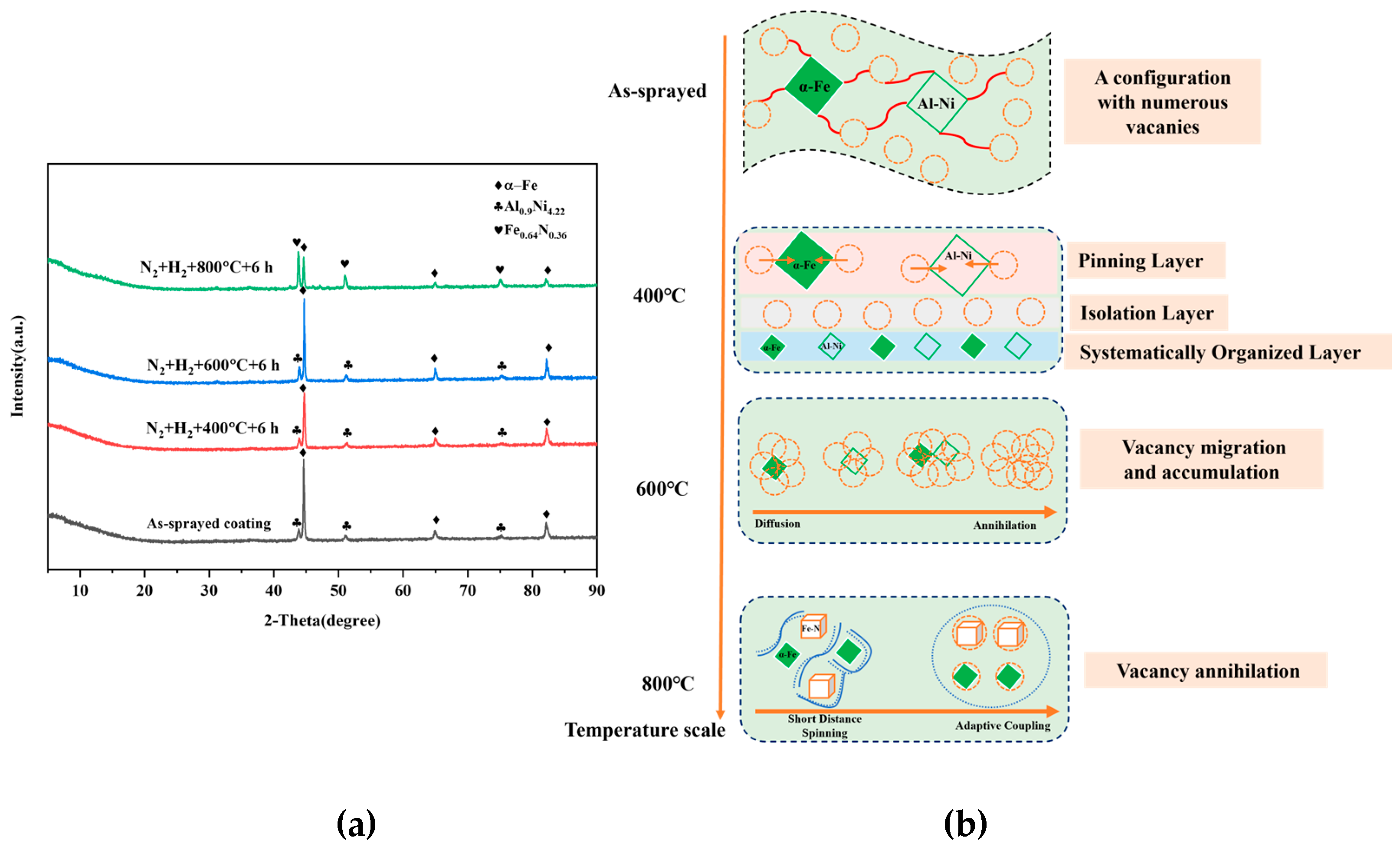
Figure 2a presents the XRD profiles of FeCoNiCrAl HEA coatings under different high-nitrogen/low-hydrogen heat treatment conditions at various temperatures. The results indicate that the as-deposited coating comprises a body-centered cubic (BCC)-structured α-Fe phase and a face-centered cubic (FCC)-structured Al0.9Ni4.22 phase. In the FeCoNiCrAl HEA coating system, the Fe element serves as the principal component. Although the atomic radius of Fe is comparable to that of other alloy elements such as Co, Ni, Cr, and Al, Fe atoms exhibit a greater propensity to form a BCC structure during the cooling process. This structural stability stems from the close-packed arrangement of Fe atoms within the BCC lattice, as well as the solid-solution strengthening effect exerted by other elements in the alloy on the Fe lattice [16]. The formation of the Al0.9Ni4.22 compound likely involves processes such as atomic diffusion, reaction, and phase transformation. Due to the solid solution and interactions among multiple elements, crystal structure distortion or transformation may occur, leading to the formation of this compound phase [17].
Table 2 presents the quantitative phase composition determination of binary phases for sequentially produced FeCoNiCrAl HEA coatings via the Rietveld refinement method. At 25 °C, the α-Fe fraction is 90.91%, which slightly increases to 91.20% at 400 °C. However, as the temperature continues to rise to 600 °C, the α-Fe fraction drops significantly to 82.27%. Finally, at 800 °C, the α-Fe fraction decreases sharply to 44.54%. The data may suggest a significant phase transformation as the temperature is elevated. Moreover, the content of the Al0.9Ni4.22 phase increases sharply at 600 °C, attributed to the increased mobility of Al and Ni atoms, allowing them to rearrange into this intermetallic compound. Fe0.64N0.36 only appears at the highest temperature (800 °C), and the corresponding fraction is approximately 55.46 wt.%, suggesting that the Fe0.64N0.36 phase may be thermodynamically stable.
As the heat treatment temperature rises from 400 °C to 600 °C, no obvious alteration in phase structure is observed in the HEA coatings. However, the intensity of the diffraction peak corresponding to α-Fe at 400 °C reduces significantly. This can be attributed to the fact that slight atomic diffusion can occur and lead to negligible phase transformation, subsequently affecting the peak intensity [18]. Nevertheless, the intensity of the diffraction peak related to α-Fe is approximately comparable to that of the as-sprayed coating when the temperature reached 600 °C. It is deemed that α-Fe can retain its stability with a body-centered cubic (BCC) structure, and no austenitization (α-Fe→γ-Fe) could occur. Moreover, Al and Cr as the solid-solution elements can suppress lattice distortion diffusion and thus inhibit phase transformation with assistance of hydrogen, which helps to hinder structural changes [19].
When the heat treatment temperature increases to 800 °C, a distinct nitride phase marked as Fe0.64N0.36 appears as the dominant structure at this temperature point. The configuration of nitrides is closely associated with crystal structure and energy. Additionally, nitrogen atoms can penetrate the coating surface or grain boundaries and subsequently react with Fe element in HEA coatings to form nitrides. As the temperature is raised to 800 °C within the nitrogen environment, the diffusion rate of nitrogen atoms will accelerate heavily, facilitating the nucleation and growth of the nitride phase [20].
A large number of vacancies inevitably exist inside the high-entropy alloy coating, which in turn will affect the phase evolution during heat treatment. Figure 3b exhibits the influence of vacancies on the phase microstructure evolution of HEA coatings during heat treatment at different temperatures. As for the as-sprayed coating, the HEA coating possesses a configuration with numerous vacancies. It is obvious that the microstructure along with the distribution of phases (such as α-Fe and Al-Ni phases) is disordered. The presence of a large number of vacancies creates a highly defective structure, which provides a starting point for subsequent microstructural changes during heat treatment [21]. As the temperature rises to 400 °C, the coating begins to undergo microstructural changes. Vacancies and other defects can act as pinning sites, restricting the movement of dislocations and grain boundaries [22]. The distribution of elements starts to show a certain degree of separation, with regions rich in different phases being more clearly defined. The vacancies may play a role in facilitating this elemental segregation by providing pathways for atomic diffusion.
When the heat temperature is 600 °C, significant migration and accumulation of vacancies accompanied by nitrogen diffusion will occur within HEA coatings. Specifically, the annihilation of vacancies can lead to local stability in atomic arrangement with a more refined and ordered state [23]. As the temperature is raised to 800 °C, the vacancy annihilation effect becomes more pronounced. It can be inferred that atoms adjacent to vacancies may undergo short-range rotation, facilitating atomic-scale rearrangement [24]. Consequently, the atomic packing and microstructural stability can be improved. Furthermore, the remaining vacancies and the surrounding atoms may undergo an adaptive coupling process, in which atomic arrangement regulates to accommodate the diminished number of vacancies. As a result, a more uniform and stationary microstructure in HEA coatings is formed.

3.2. Electrochemical Corrosion Responses

3.2.1. EIS Responses

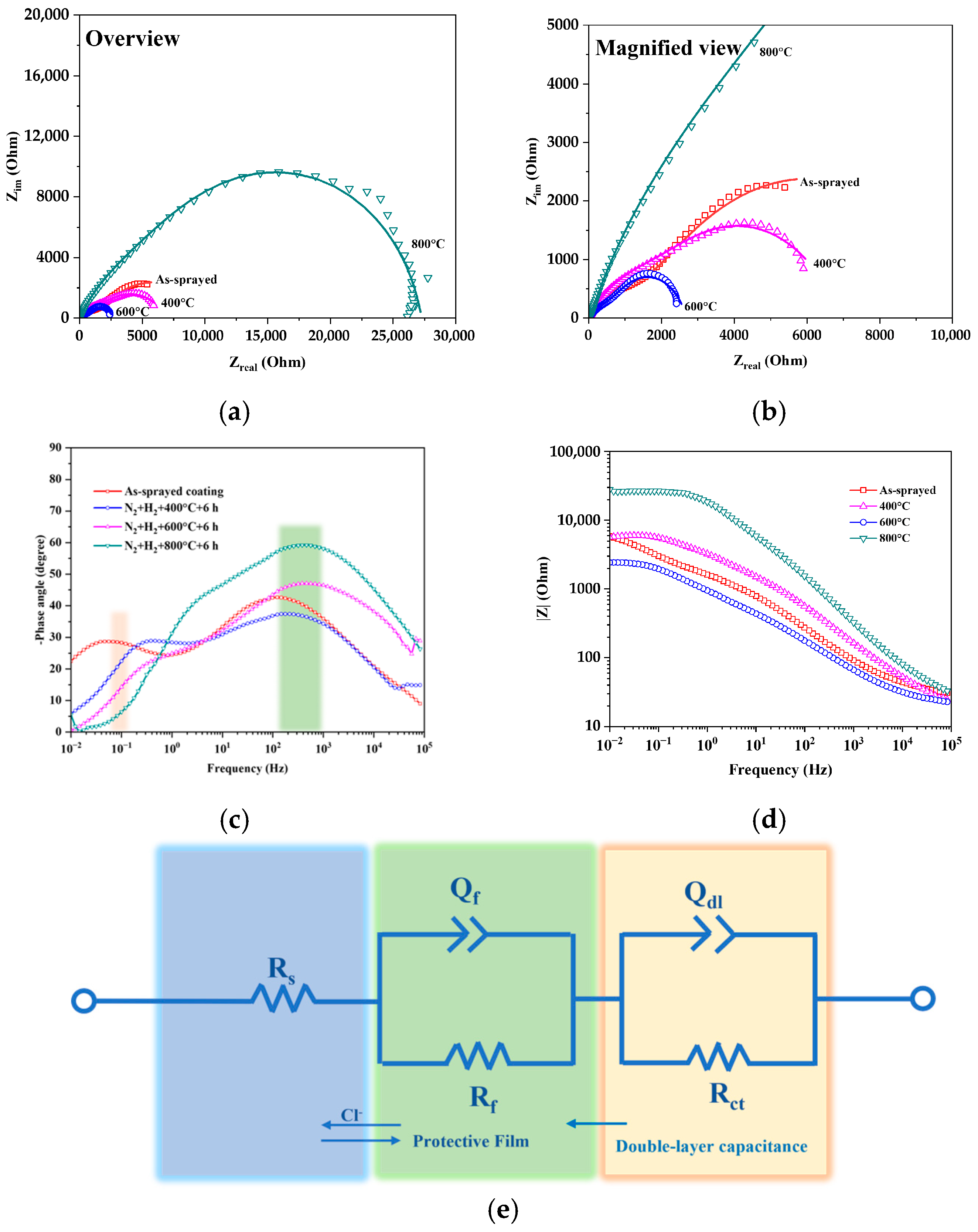
Figure 3a–d show the Nyquist and Bode plots of FeCoNiCrAl HEA coatings under different high-nitrogen/low-hydrogen heat treatment conditions. According to the results in Figure 3a,b, when the heat treatment temperature gradually changes from the as-deposited state to 600 °C, the diameter of the electrochemical impedance spectroscopy plot gradually decreases, indicating that the corrosion resistance of the coating gradually weakens. At relatively low temperatures (400 °C), the extent of the reaction is limited. The dense nitride protective layer formed on the material surface is not well-developed, resulting in a relatively weak hindrance to corrosive media. Therefore, the radius of the impedance plot is relatively small.
At higher temperatures (600 °C), the diffusion and reaction among alloy elements are more intense, which may lead to uneven element distribution or the formation of new phases. The surface layer formed may be unstable or easily damaged, thereby reducing the corrosion resistance. When the temperature rises to 800 °C, the diameter of the corresponding EIS plot increases sharply, indicating that the FeCoNiCrAl HEA coating has the best corrosion resistance at this temperature. Based on the previous XRD pattern results, this indicates that Fe-containing nitrides appear inside the HEA coating at this temperature. These nitrides have high chemical stability and a relatively dense structure, which can resist the erosion of chloride ions.
From the phase angle frequency domain characteristics in Figure 3c, coatings subjected to different temperature heat treatments show significant extreme value differences across frequency ranges. In the low-frequency range of 10−2 to 10 Hz, the as-sprayed coating has the maximum phase angle, while the 800 °C-treated one shows the minimum. In the mid-frequency range of 10 to 103 Hz, the maximum appears in the 800 °C-treated coating and the minimum in the 400 °C-treated one. At 103–105 Hz, the extremes remain the same, indicating better corrosion resistance of the 800 °C-treated coating. Figure 3d depicts the impedance magnitude (|Z|) as a function of frequency (Hz) for all the coatings. The curve of the 800 °C-annealed coating shows the highest impedance magnitude across the entire frequency range compared to the other coatings. At lower frequencies (below 1 Hz), the differences in the impedance magnitude between the conditions are more pronounced. This indicates that microstructural transformation induced by the 800 °C heat treatment can crucially strengthen the impedance magnitude.
The EIS data were fitted using the equivalent circuit shown in Figure 3e. In this circuit, Rs represents the resistance of the corrosive solution, Rf and Qf represent the fitted impedance and capacitance values of the passive film, respectively, and Rct and Qdl represent the impedance and capacitance values of the electric double-layer capacitance, respectively.
The corresponding fitting data are presented in Table 3. When the temperature changes to 400 °C, the Qdl value increases, the n value decreases, and the corresponding Rct value also decreases. However, the Rf value increases, while the Qf value decreases. These results indicate that the changes in the corrosion resistance of the electric double-layer capacitance and the passivation film are not consistent. This is attributed to the fact that the capacitive characteristics of the HEA coating after immersion mainly depend on the charge distribution on the electrode surface and the adsorption of counter-ions in the solution [25]. The electrostatic repulsion effect prevents the approach of oppositely charged ions in the solution to the electrode surface, thereby slowing down the corrosion reaction to a certain extent [26]. However, after heat treatment at 400 °C, this electrostatic repulsion effect is relatively weak, and the blocking effect on some small-sized and highly active corrosive ions is limited.
When the heat treatment temperature reaches 600 °C, the corrosion resistance of both the electric double-layer capacitance and the passive film weakens, which is reflected in the decrease in the transfer charge resistance Rct and the fitted passive film impedance Rf. When the heat treatment temperature increases to 800 °C, the trend of improving corrosion resistance becomes more pronounced. In particular, the transfer charge resistance Rct reaches 19,190 Ω·cm2, and the fitted passive film impedance Rf reaches 8073 Ω·cm2. This proves that high-temperature heat treatment in a high-nitrogen/low-hydrogen atmosphere is beneficial for enhancing the corrosion resistance of HEA coatings. This mainly originates from the aggregation effect of nitrogen within the coating, which can inhibit the dissolution of the strongly passivating element Cr [27]. Previous studies have shown that nitrogen is enriched on the metal side close to the metal interface in the passivation film, affecting the re-passivation kinetics and promoting rapid re-passivation of the stainless steel surface. This phenomenon in turn inhibits the autocatalytic process of pitting corrosion and reduces the dissolution of Cr.

3.2.2. Analytical Standardization of EIS Data

Figure 4 depicts polar bubble charts derived from EIS data by the analytical standardization method with assistance of OriginPro 2024 software. This image provides valuable insights into the electrochemical corrosion performance under different heating temperatures. For the as-sprayed coating, the spread of data indicates scattering variability in the EIS response, possibly owing to the inherent inhomogeneity. Compared to the as-sprayed coating, a noticeable shift in impedance magnitude is observed for the coating annealed at 400 °C. It is revealed that there is a more concentrated distribution of data at various angles under this circumstance, implying a more uniform response for corrosion behavior. As the temperature approaches 600 °C, a significant reduction in impedance values at some angles is detected. In addition, the dispersion of data points is more pronounced, suggesting increased variability in the EIS data. When the heating temperature is raised to 800 °C, the impedance exhibits a much higher magnitude than previous states, indicating a substantial transformation in the microstructure strengthened by the Fe0.64N0.36 nitride phase. This analytical standardization method highlights the valuable collaboration with a N2/H2 mixed atmosphere.

3.2.3. Potentiodynamic Polarization Measurements

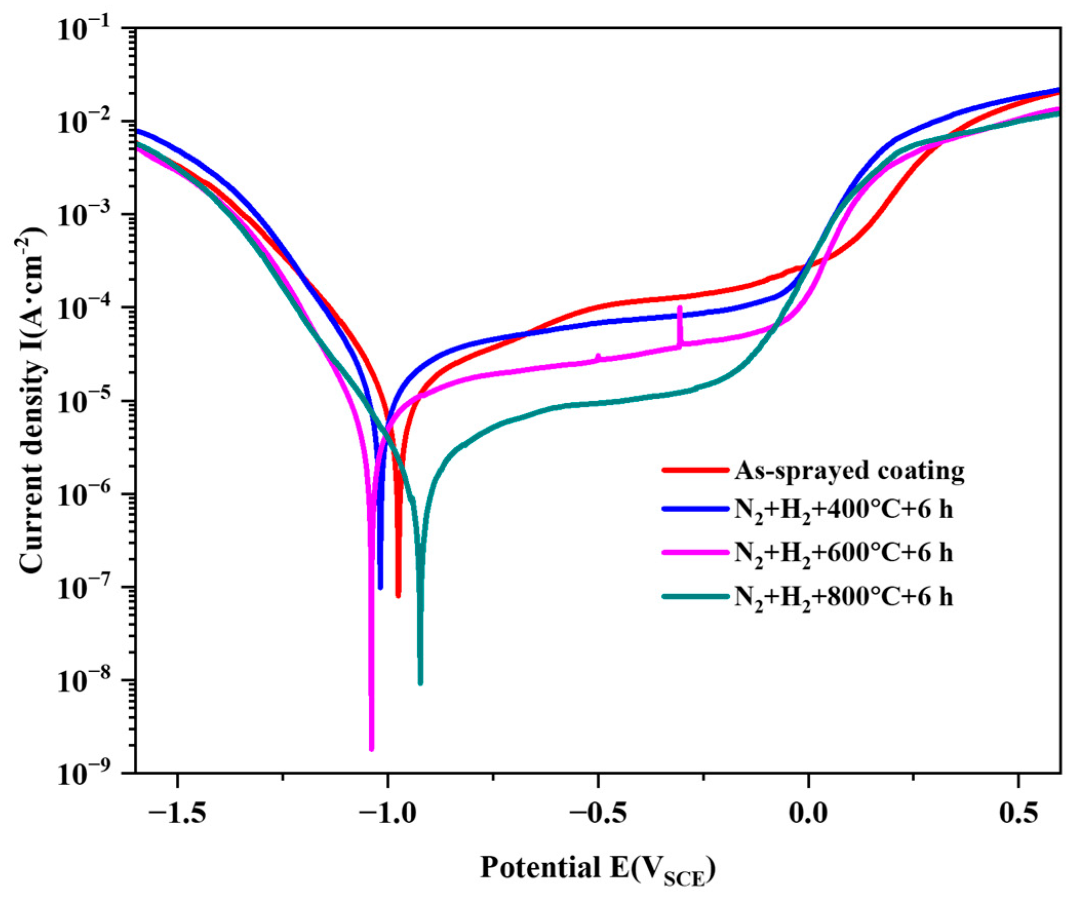
Figure 5 displays the potentiodynamic polarization curves of FeCoNiCrAl HEA coatings under different high-nitrogen/low-hydrogen heat treatment conditions. The corresponding key electrochemical parameters are presented in Table 4. It can be seen that all the curves exhibit similar characteristics with a distinct passivation region. When the temperature reaches 600 °C, the corrosion potential drops significantly (−1039 mV), suggesting that the coating has the strongest corrosion tendency. As the temperature reaches 800 °C, the corrosion potential Ecorr is the highest at −923 mV, and the coating has the lowest corrosion tendency at this temperature. Correspondingly, the corrosion current density (Icorr) is only 1.64 μA/cm2 at 800 °C, which is the smallest value. This further proves that the HEA coating annealed at 800 °C has the best corrosion performance.
The pitting potential (Epit) reaches the minimum at 800 °C. This is because Fe-containing nitrides precipitate within the HEA coating at this heat treatment temperature, which is a secondary phase precipitation. There is a chemical potential difference between the secondary precipitate phase and the HEA coating matrix. The regions where the secondary precipitate phase/metal matrix form a galvanic cell are considered the sites in which the passive film dissolves first and may serve as the initiation sites for pitting corrosion in an aggressive solution, leading to a significant decrease in the pitting potential [28]. In the case of 800 °C, the transformation involving the generation of the new phase Fe0.64N0.36 may induce galvanic corrosion between the matrix and the new phase. The new phase might be more cathodic relative to the surrounding matrix, leading to local corrosion reactions. In other words, the structural integrity that provides better corrosion performance is deteriorated. However, nitrides can enhance the protective properties by forming strong chemical bonds with other elements in the passive film. The modification of the passive film composition can result in a lower corrosion rate, as reflected by the smaller corrosion current density and carrier densities.
However, the passivation current density (Ipass) does not follow the same trend as the pitting potential. After heat treatment at 800 °C, the Ipass of the HEA coating was 33.3 μA/cm2, indicating a better passivation performance of the coating at this temperature. This is because Me-N bonding is more chemically inert than Me-Me bonding. The participation of nitrogen helps improve the corrosion resistance of the HEA coating. Thus, the precipitation of the secondary nitride phase may further enhance this corrosion resistance, making the HEA coating more resistant to erosion in corrosive media. Meanwhile, the trend of polarization resistance (Rp) is basically consistent with that of the passive current density, further proving the significant improvement effect of nitrides on the corrosion performance.

3.2.4. Effective Capacitance Model Analysis

In this study, the power-law formula introduced by Hirschorn, which is one of the three-dimensional distribution models, was utilized to derive an effective capacitance value C e f f from the constant phase element (CPE) parameters. Correspondingly, the effective capacitance C e f f is formulated as follows [29]:
C e f f = g Q ( ρ δ ε ε 0 ) 1 n
where Q represents the fitted parameter obtained from the equivalent electrical circuit; g is a parameter expressed as a function of the fitted n in Table 2 ( g = 1 + 2.88 (1 − n )2.375); ρ δ is the lower limit of resistivity estimated at x = δ; ε is the relative permittivity taken as 15.6 [30]; and ε0 is the vacuum permittivity valued at 8.854 × 10⁻¹⁴ F/cm2. Although determining ρ δ directly is challenging, its upper bound ρ δ ,   m a x can be obtained from the following equation [31]:
ρ δ ,   m a x = 1 2 π ε ε 0 f m a x
Here, f m a x denotes the highest frequency measured, which is 100,000 Hz in this study. As a result, the maximum effective capacitance, Ceff,max, can be determined as follows:
C e f f ,   m a x = Q g ( 2 π f m a x ) n 1
The minimum thickness d m i n of the passive film and double-layer capacitance correlating with the capacitance value is expressed as follows [29]:
d m i n = ε ε 0 A C e f f ,   m a x
where A represents the effective surface area of the samples, which is 1 cm2 in the present study.
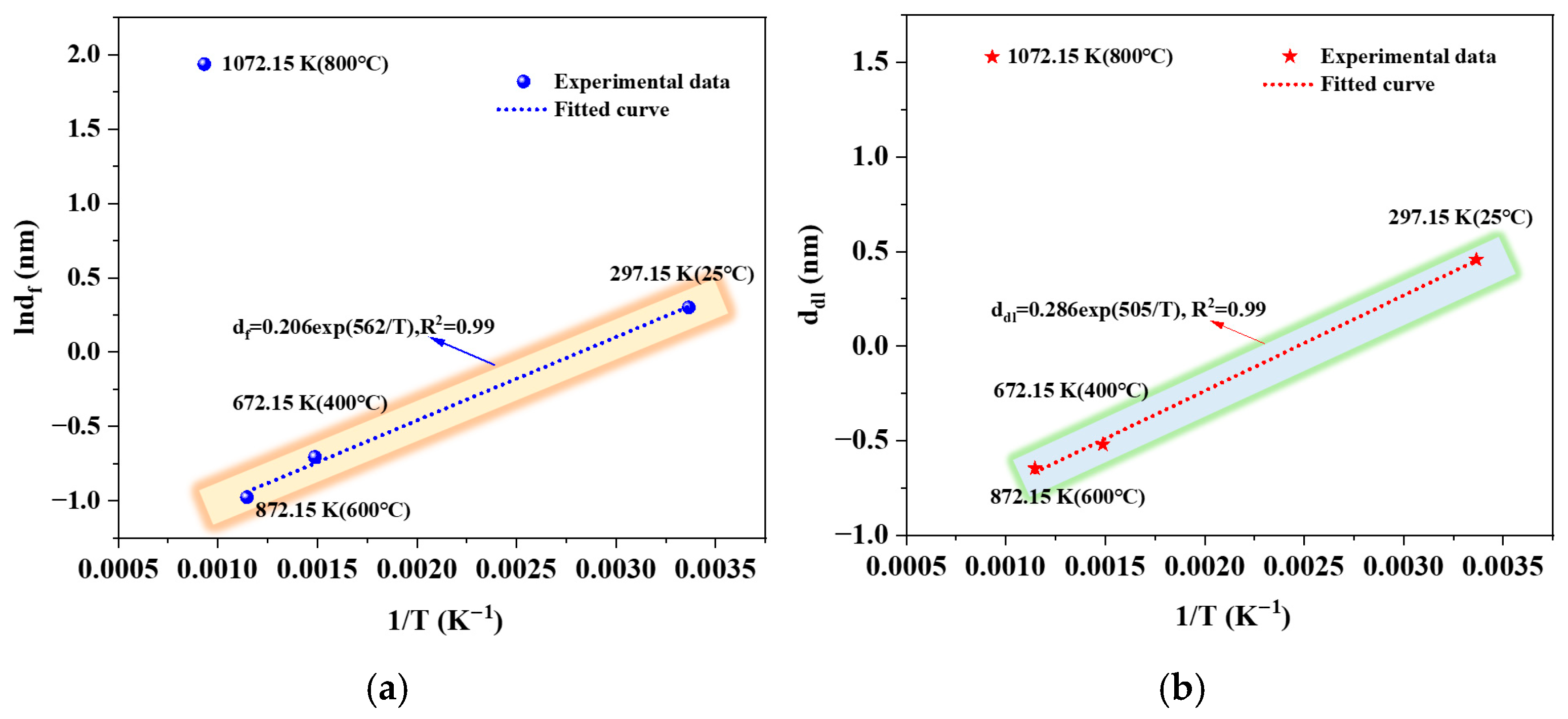
Figure 6 displays the temperature-dependent performance of the passive film and double-layer capacitance thicknesses based on the effective capacitance model, as mentioned above. It can be seen that both the passive film thickness and double-layer capacitance thickness indicate exponential correlations with the reciprocal of temperature (1/T) when the annealing temperature ranges from 25 °C to 600 °C, suggesting that the input thermal energy heavily influences the growth of these layers. In addition, the maximum values of both the passive film and double-layer capacitance are ascertained at 800 °C (1072.15 K), implying a structural pattern in which the thermal energy surpasses the impetus for layer growth and stabilization of double-layer capacitance.
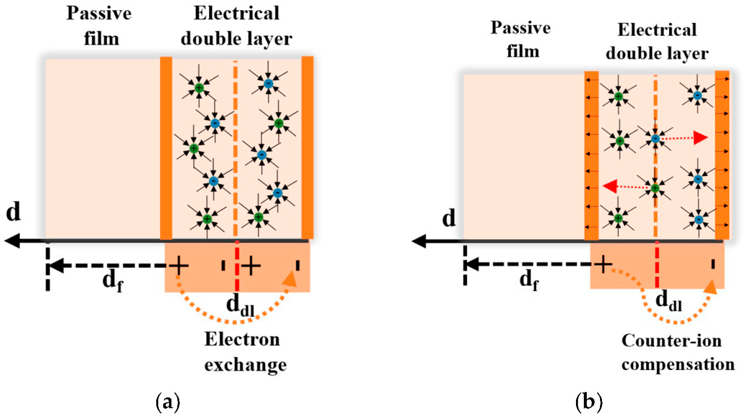
The microstructural structure composed of the passive film and electrical double-layer capacitance along with the ion exchange mechanism is depicted in Figure 7. The procedure involving electron exchange occurring at the film/layer interface is highlighted in Figure 7a. The presence of cations or electrical holes within positively charged regions facilitates electron exchange between the double-layer capacitance and solution [32]. It means that the migration of counter-ions effectively neutralizes both the positive and negative charges within the double-layer capacitance [33]. This compensation mechanism, as illustrated in Figure 8b, can maintain the total charge neutrality and functionality of the film/layer interface, which can protect the present HEA coatings from degradation.

3.2.5. Semiconducting Performance

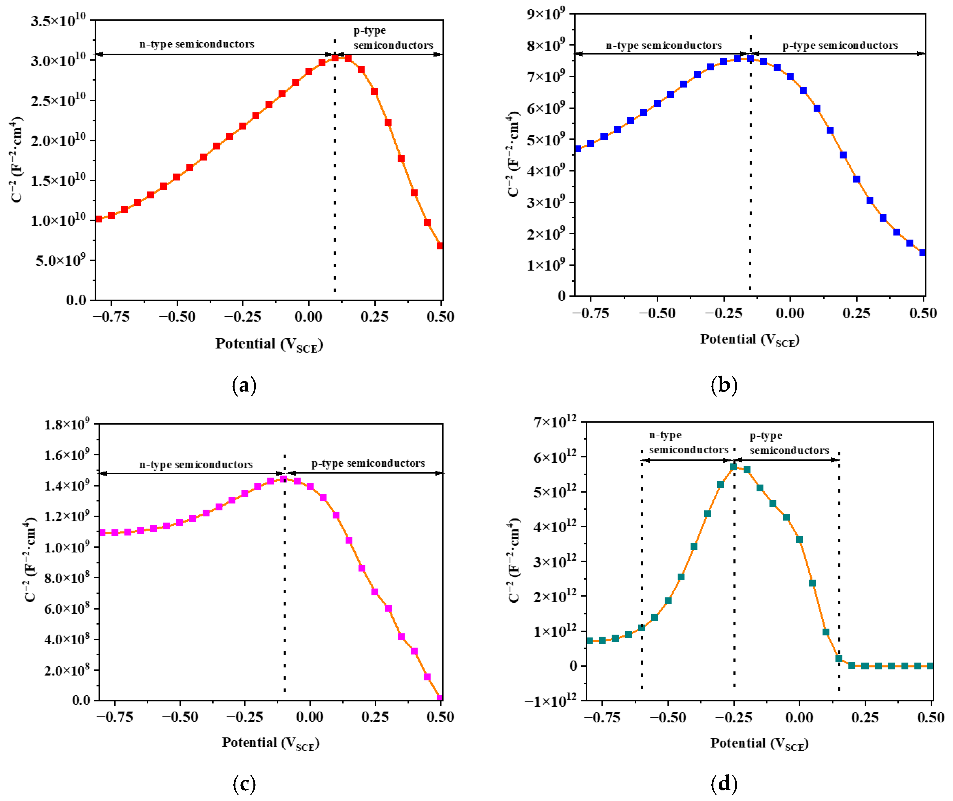
Mott–Schottky analysis can be employed to characterize the evolving semiconducting and electronic characteristics of passive films formed on metal alloys. Consequently, the double-layer capacitance C as a function of the externally applied potential E can be described by the following equation [34]:
1 C 2 = ± 2 ε ε 0 e N ( U U f b k B T e )
Here, the positive and negative signs correspond to n-type and p-type semiconductors within the film, respectively. The symbol ε represents the relative dielectric constant of the dopants, ε0 is the vacuum permittivity (8.854 × 10⁻¹² F/m), e denotes the elementary charge (1.6 × 10⁻¹⁹ C), N indicates the donor or acceptor density, Ufb signifies the flat-band potential, kB is the Boltzmann constant (1.38 × 10⁻²³ J/K), and T represents the absolute temperature of the corrosive environment.
Mott–Schottky curves in terms of the external applied potential E of sequentially produced FeCoNiCrAl HEA coatings are displayed in Figure 8. It is noted that all curves indicate the coexistence of both n-type and p-type semiconductors occurring in the passive film. Consequently, Table 5 provides a detailed overview of the estimation for critical fitting results including dopant and acceptor concentrations. As illustrated in Figure 8, the left-hand artificially fitted curves with positive slopes stand for n-type semiconductors, in which oxygen vacancies or cation interstitials principally perform as donor species [35]. Conversely, the right-hand convoluted plots reveal p-type semiconducting behavior, which is primarily regulated by cation vacancies as acceptor species [36].
It can be seen that the donor density is 3.41 × 1020 cm−3, while the acceptor density is regarded as 2.13 × 1020 cm−3 for the as-sprayed coating. When the annealing temperature increases to 400 °C, both the donor and acceptor densities increase, attaining 1.08 × 1021 cm−3 and 1.37 × 1021 cm−3, respectively. As the heat treatment temperature increases to 600 °C, a significant rise was observed in both the donor and acceptor densities, with the dopant density and acceptor density escalating to 6.39 × 1021 cm−3 and 6.56 × 1021 cm−3, respectively. However, a notable reduction in both the donor and acceptor densities was ascertained, with values declining to 9.86 × 1017 cm−3 and 3.15 × 1018 cm−3, respectively. This indicates that 800 °C is an optimal point for more compact passive films with a less defective structure, owing to the formation of nitride in the HEA coating, which can enhance the electronic structure of passive films.

3.3. Tribological Properties

3.3.1. Frictional Coefficients

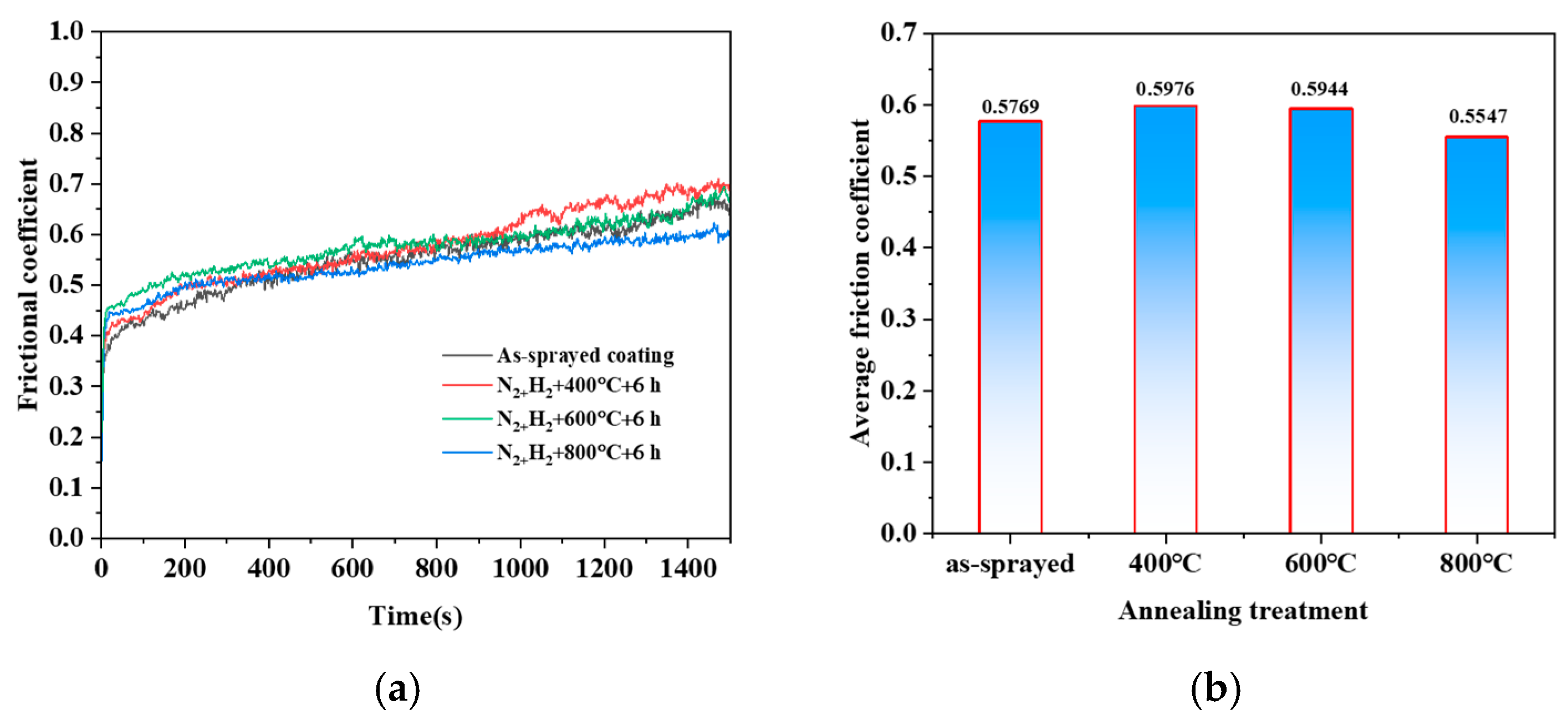
Figure 9a shows the evolution curves of the coefficient of friction over time for the FeCoNiCrAl HEA coating after heat treatment at 400 °C, 600 °C, and 800 °C in a high-nitrogen/low-hydrogen (N2:H2 = 3:1) atmosphere. As depicted in the figure, the coefficient increases rapidly in the initial stage following heat treatment at different temperatures, then stabilizes with minor fluctuations, ultimately reaching a steady value. The variations in the average friction coefficient of sequentially prepared HEA coatings are displayed in Figure 9b. It can be seen that the as-sprayed coating exhibits an average friction coefficient of 0.5769. After annealing at 400 °C, the average friction coefficient evidently increases to 0.5976. At 600 °C, the average friction coefficient remains relatively stable at 0.5944, showing a slight decrease compared to the 400 °C treatment. The highest annealing temperature of 800 °C results in the lowest average friction coefficient of 0.5547 among the treated samples. As evidenced by the above results, it can be concluded that the friction coefficient at 800 °C decreased by 3.84% compared to that in the as-sprayed state due to the formation of a denser nitride layer. A lower friction coefficient implies that the coating possesses better wear resistance and lubricating properties in practical applications, which is of great significance for enhancing the service life of the coating.

3.3.2. Worn Surfaces

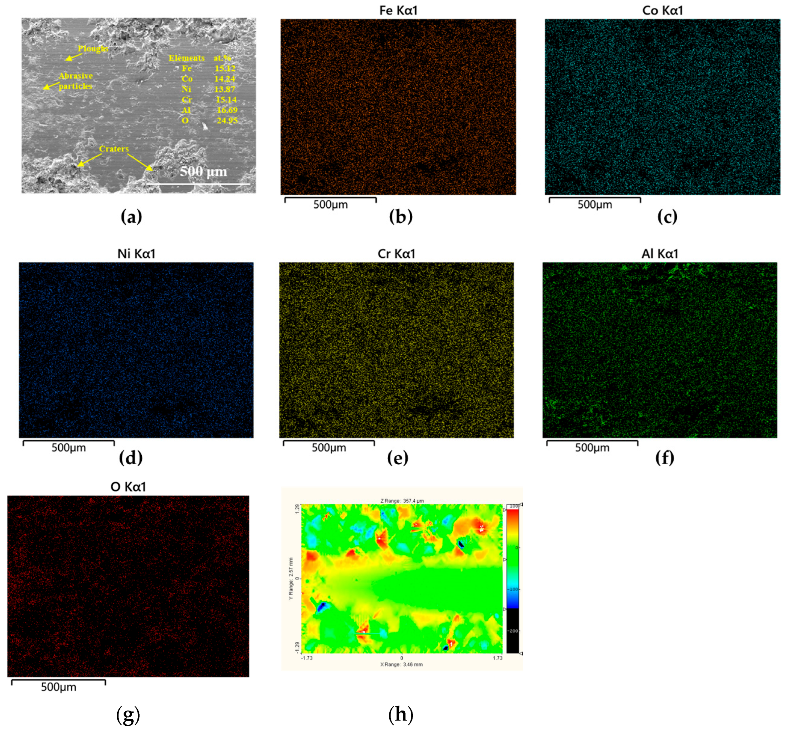
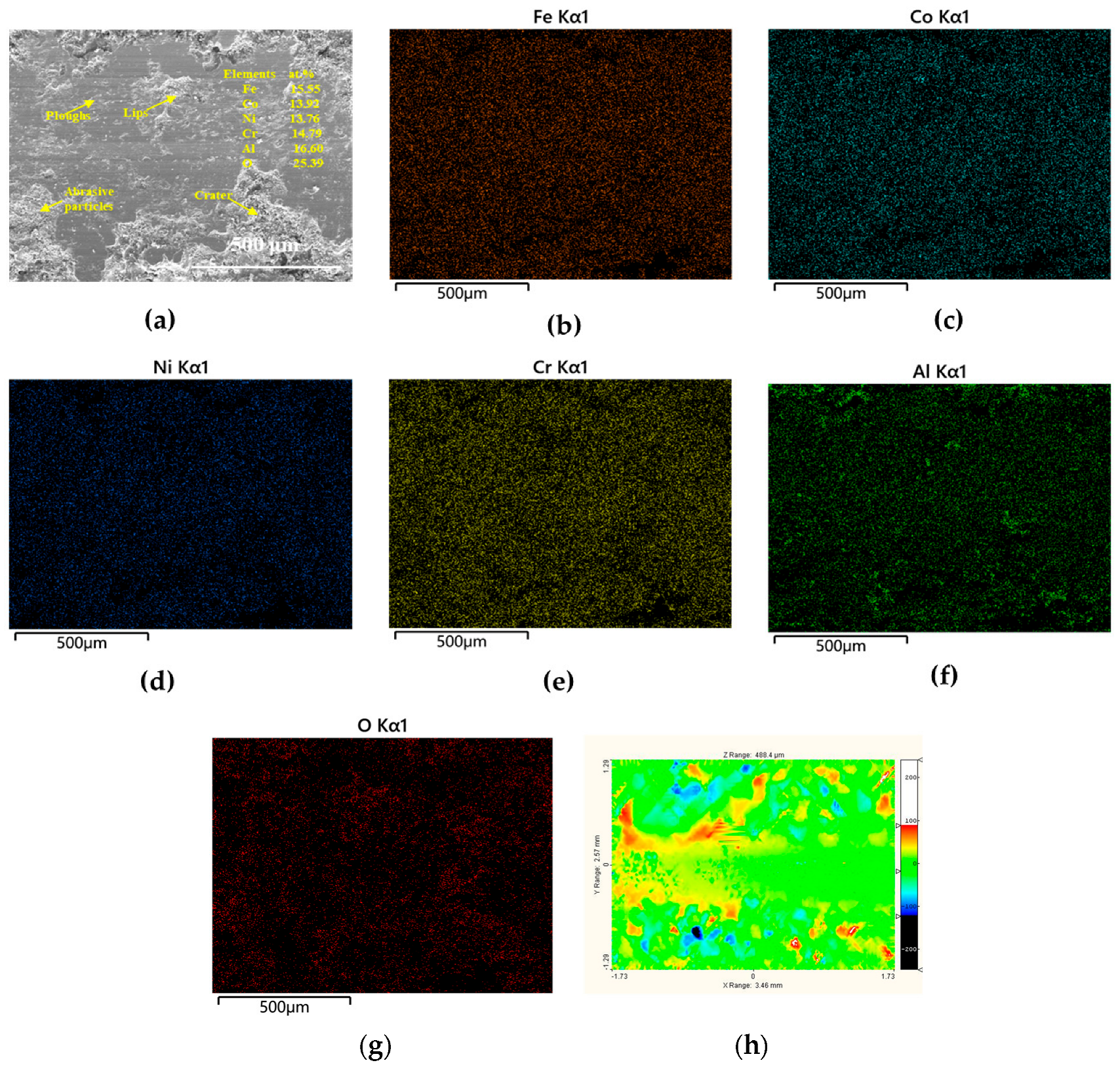
Figure 10 presents the worn traces, EDS mapping results, and 3D topographic morphology of the as-sprayed FeCoNiCrAl HEA coating after the wear test. Figure 10a indicates the worn topography, revealing the presence of ploughing marks and abrasive particles. These features indicate that abrasive wear is a dominant mechanism, where hard particles or asperities slide across the surface, causing material removal [37]. The presence of a crater suggests localized plastic deformation and material removal due to the high contact stresses during the wear process. The elemental maps in Figure 10b–g show the distribution of various elements within the worn region. The uniform distribution of these elements indicates that the coating maintains its compositional integrity during wear, which is crucial for sustaining its mechanical properties. The presence of oxygen (O Kα1 map) suggests that oxidation may occur on the worn surface, forming an oxide layer that can influence wear behavior by acting as a protective or lubricating film [38].
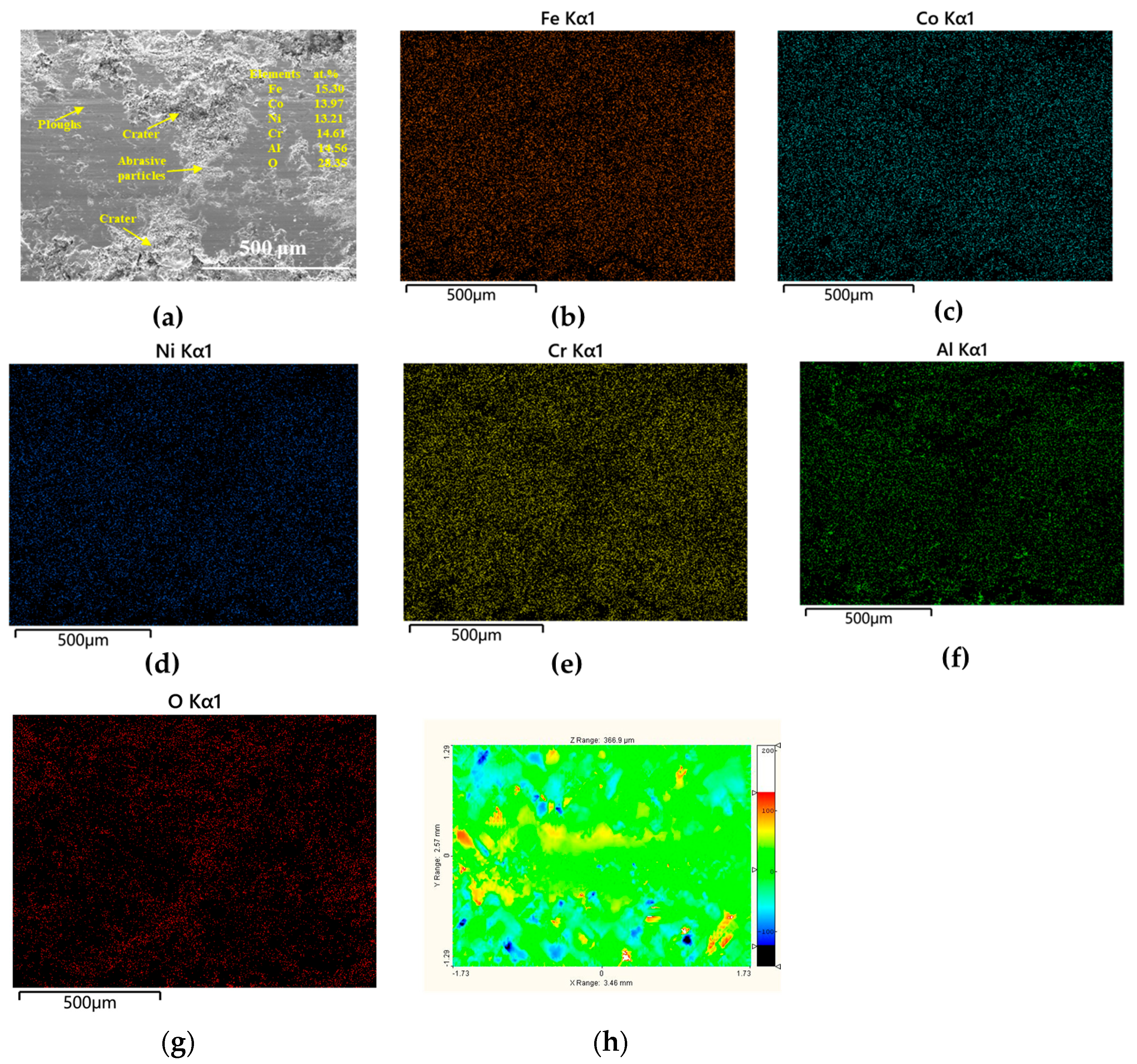
Figure 11 exhibits the worn morphology of the HEA coating annealed at 400 °C, highlighting ploughing and abrasive particles, which is similar to the results in Figure 10. Notably, the formation of lips on the worn surface is derived from plastic formation or owing to frictional loads and mechanical stresses encountered during wear process [39]. Lips can act as stress concentrators, feasibly leading to coating removal or crack initiation, thereby influencing the total durability of the HEA coating. The elemental distribution maps of Fe, Co, Ni, Cr, and Al indicate that the coating can retain its compositional stability during the wear procedure. It is also noted that oxidative wear can occur, as implied by the oxygen EDS mapping result.
Figure 12 displays the worn traces of the FeCoNiCrAl HEA coating annealed at 600 °C. Distinct features including ploughing, abrasive particles, and craters are marked in Figure 12a, suggesting that the wear process may involve the deformation and removal of the coating surface interacting with hard particles. The EDS mappings for Fe, Co, Ni, Cr, Al, and O elements in Figure 12b–g demonstrate a relatively homogeneous distribution of elements across the worn area. As a result, the inherent mechanical properties of the HEA coating can be sustained. The presence of oxygen, as indicated by the O elemental EDS map, implies the possible oxidation of the coating surface.
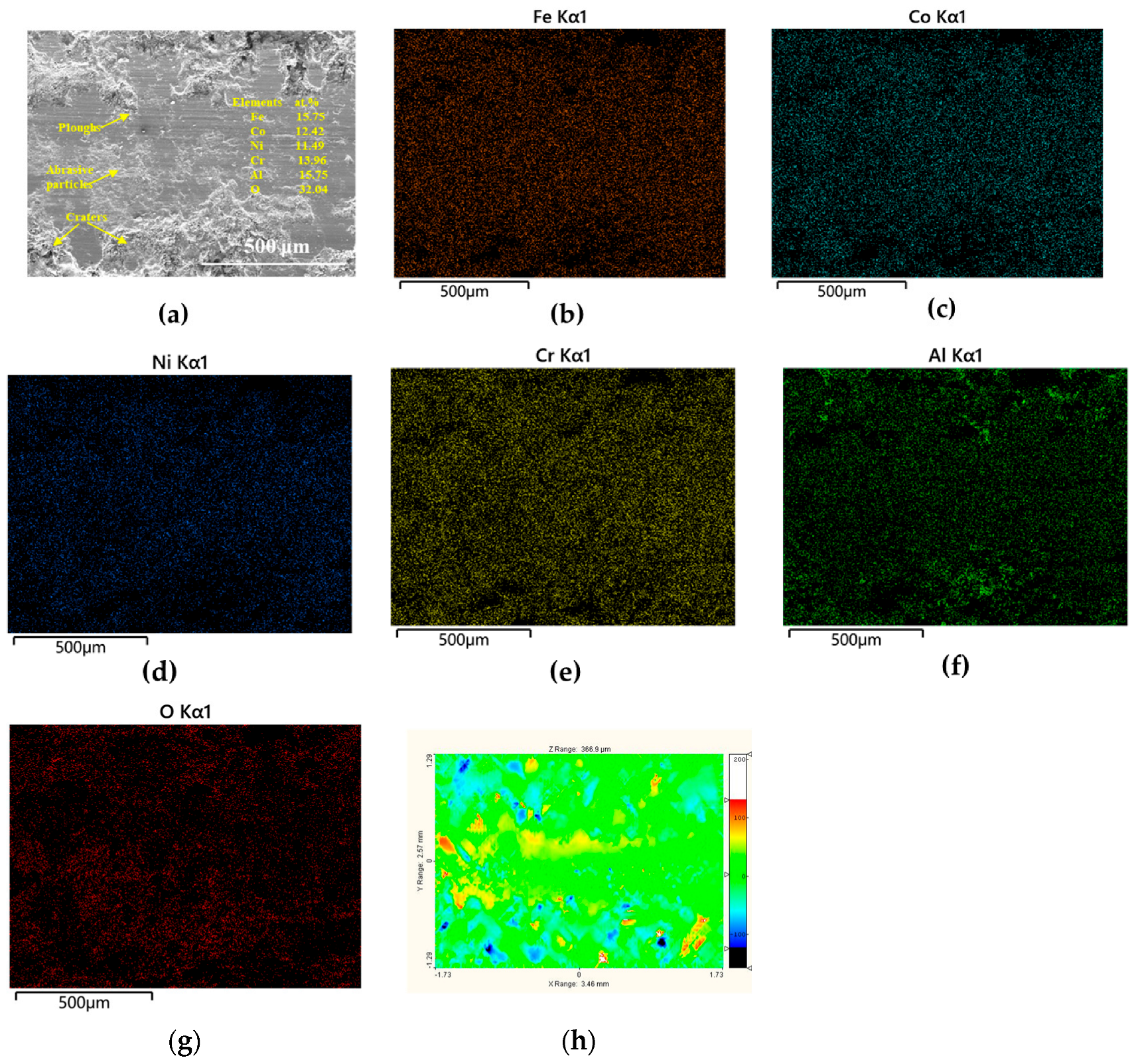
Figure 13 illustrates the worn morphology of wear traces corresponding to the FeCoNiCrAl HEA coating annealed at 800 °C. The appearance of ploughing and abrasive particles suggests coating displacement with material removal. The EDS mapping results of Fe, Co, Ni, Cr, Al, and O in Figure 13b–g still show a uniform distribution of elementary regions. The existence of oxygen indicated by O element mapping exhibits the potential oxidation during the wear process. It is deemed that surface oxidation can lead to the maturation of a protective layer, which may mitigate the disturbance of direct contact from counterparts.
Figure 10h, Figure 11h, Figure 12h, and Figure 13h present the wear morphology contour maps of sequentially prepared FeCoNiCrAl HEA coatings. The maximum roughness in the Z direction for the FeCoNiCrAl HEA coatings after heat treatment at different temperatures is illustrated as 357.4 µm, 488.4 µm, 388.9 µm, and 343.4 µm, respectively. These results indicate that the surface of the HEA coating becomes smoother after heat treatment at 800 °C. The incorporation of nitrogen induces a certain degree of lattice distortion adjustment within the coating, while the low-hydrogen environment reduces the adverse effects of hydrogen on the coating surface, such as hydrogen embrittlement, resulting in a more ordered atomic arrangement on the surface [40]. Driven by both thermal activation and the atmospheric environment, the surface atoms continuously undergo ordered rearrangement [1]. This ordered surface structure reduces the interaction between surface atoms and the wear medium, lowers the friction coefficient, and ultimately enhances wear resistance.

4. Discussion

4.1. Molecular Orbital Theory-Based Analysis

Figure 14 depicts a comprehensive view of the internal structural evolution of HEA coatings from the perspective of molecular orbital theory. The concepts of bonding and antibonding interactions can be analyzed within the framework of a yin–yang model symbolizing the dynamic balance of activation and suppression processes. The “Bond Formation” part in the diagram is closely related to the formation of molecular orbitals. In HEA coating systems, different atomic species contribute valence electrons to form molecular orbitals. For instance, the 2p orbitals of certain atoms can overlap and combine to create bonding and antibonding molecular orbitals (such as σ2p, σ2p*, π2p, and π2p*) [41]. The bonding molecular orbitals are lower in energy and tend to stabilize the system by promoting interaction between atoms. As the alloy undergoes processes like electron excitation, the electrons can be promoted from lower-energy molecular orbitals to higher-energy ones, which may trigger subsequent structural changes [42].
As illustrated in Figure 14, antibonding interaction means the existence of high-energy antibonding molecular orbitals. As the electrons occupy antibonding molecular orbitals, the atomic bonds will be weakened, thus making the microstructure more susceptible to transfiguration. The localized bond-breaking is significantly influenced by the structural allocation of electrons in molecular orbitals and microstructural defects such as vacancies, which can serve as stress concentrators and foster internal bond-breaking [43]. In other words, the occupation of antibonding orbitals in HEA coatings will enable internal breaking, in which the atomic bonds can be damaged, giving rise to re-organization on the atomic scale.
The right-hand portion in the yin–yang model depicted in Figure 14 signifies the activation process involving thermal dissociation, in which input thermal energy can break the existing atomic bonds. In this investigation, electron excitation is crucial in activation and initiates the breaking of atomic bonds, allowing electrons to transfer to antibonding orbitals [44]. Hence, subsequent structural evolution can occur in HEA coatings with assistance of heat treatment. The left-hand part in the yin–yang model represents the suppression procedure regarding homolytic cleavage, which provides the even breaking of bonds by releasing two free radicals [45]. This process can be suppressed due to the selective inhibition effect of highly reducing hydrogen, which helps to maintain the structural stability to some degree. Therefore, it can be concluded that the appropriate balance between activation and suppression can provide a complementary effect between nitrogen and hydrogen in the mixed heat treatment atmosphere.

4.2. Point Defect Model (PDM) Elucidation

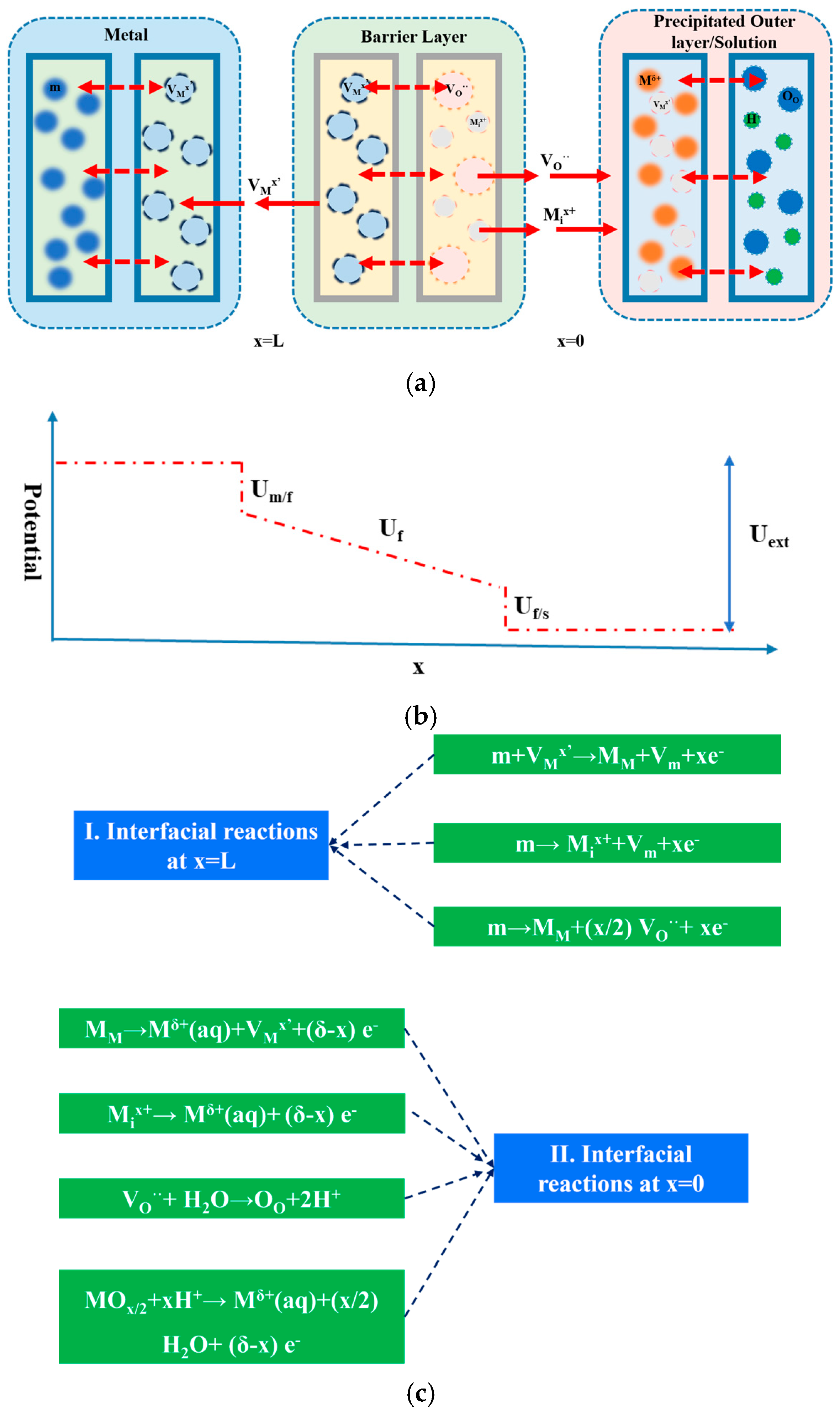
The PDM provides insights explaining the formation and breakdown of the passive film at an atomic level, as presented in Figure 15. The schematical diagram can be separated into three segments: (a) a typical representation of the coating, barrier layer, and precipitated outer layer; (b) a potential drop as a function of distance; and (c) a compilation of possible reactions associated with point defects [46,47]. The first segment in Figure 10a displays the coating surface comprising metal atoms (m) and metal vacancies (VMx’). The central segment in Figure 10a depicts the barrier layer formed as a consequence of interplays between metal ions (Mix+) and oxygen vacancies (VO··). The ultimate segment in Figure 10a illustrates the outside precipitated layer exposed to the solution, exhibiting the presence of metal ions (Mδ+) and oxygen species (OO).
The PDM and the effective capacitance model are interconnected through their shared focus on quantifying and modeling the behavior of passive films on the coating surface, particularly in the context of corrosion and electrochemical systems. The PDM explains the microscopic mechanisms associated with defect generation, migration, and accumulation that dominate passive film behavior. The effective capacitance model translates these mechanisms into macroscopic electrical properties that can be measured experimentally. Thus, they provide a comprehensive framework for understanding and predicting corrosion resistance, film stability, and electrochemical performance of the coating surface.
Figure 15b illustrates how the potential varies across different interfaces within the HEA coating system under the effect of a total external potential (Uext). The potential undergoes a step change at the coating/barrier layer interface. This means that the initial energy barrier should be overcome for the reaction between metal atoms and the passive film. As the distance from the coating/film interface to the barrier layer increases, the potential (Uf) decreases progressively. This can lead to the migration of charged species such as metal ions and oxygen vacancies through the barrier layer under the internal electrical field. Another step can be observed at the interface between the barrier layer and electrolyte. It implies that the transfer of ions between the layer and solution must conquer the energy barrier and promotes the dissolution and adsorption of species from the electrolyte onto the film [48].
Figure 15c presents a series of electrochemical reactions occurring in the context of passive film formation and breakdown on a metal surface, as part of the PDM. The reactions are labeled from (1) to (7) and are described in terms of the changes happening along the spatial coordinate x, which ranges from x = L (the metal/film interface) to x = 0 (the film/solution interface) [49,50]. Reaction (1) indicates that a metal atom (m) reacts with a metal vacancy (VMx’) to form a metal ion at a lattice site (MM) and a Schottky-type vacancy (Vm) and releases x electrons. Reaction (2) represents a metal atom (m) being oxidized to form an interstitial metal ion (Mix+) and a Schottky-type vacancy (Vm) and releasing x electrons. A metal atom (m) is oxidized to form a metal ion at a lattice site (MM) and interacts with (x/2) oxygen vacancies (VO··) in Reaction (3). A metal ion at a lattice site (MM) dissolves into the aqueous phase as Mδ+(aq), as illustrated in Reaction (4). An interstitial metal ion (Mix+) dissolves into the aqueous phase as Mδ+(aq), as presented in Reaction (5). An oxygen vacancy (VO··) reacts with water to form an oxygen ion at a lattice site (OO) and releases two protons (2H+) in Reaction (6). Reaction (7) denotes that a metal oxide species (MOx/2) reacts with x protons (H+) to dissolve into the aqueous phase as Mδ+(aq), forms (x/2) water molecules, and releases (δ-x) electrons. This reaction spans the entire film, from x = L to x = 0.
These reactions collectively describe the dynamic processes of metal dissolution, oxide formation, and defect migration that occur at the metal/film and film/solution interfaces, providing a comprehensive understanding of the electrochemical behavior of passive films.

4.3. Wear Mechanisms

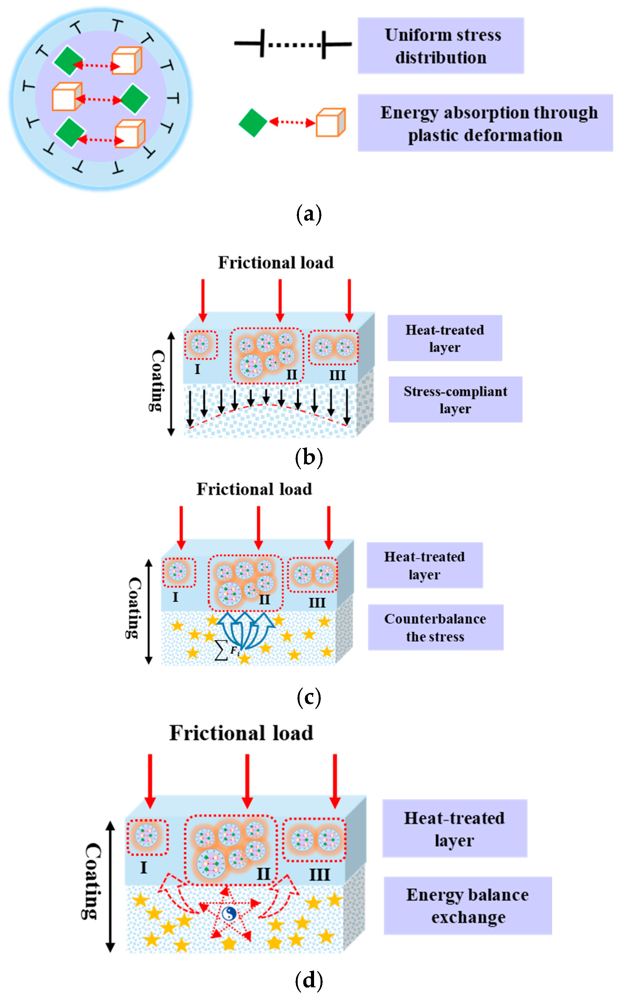
It is evident that nitriding at 800 °C with the assistance of nitrogen and hydrogen is a promising technique for FeCoNiCrAl HEA coatings to relieve wear scratches. Therefore, the relationship between the internal structural transformation of FeCoNiCrAl HEA coatings and the wear mechanism after 800 °C annealing is illustrated in Figure 16. A unit with uniform stress dissemination within the HEA coating aligned with energy adsorption through plastic deformation between α-Fe and nitrides is depicted in Figure 16a. The associated structural transformations occurring in the HEA coating system under a frictional load are displayed in Figure 16b,c. As illustrated in Figure 16b, the HEA coating can be divided into three regions (marked as region I, II, and III), comprising a heat-treated layer and a stress-compliant layer. It can be concluded that the heat-treated layer can enhance the surface mechanical properties, while the stress-compliant layer is beneficial for accommodating the applied stress from an external load [51].
The importance of the heat-treated layer is undermined in resisting wear behavior, as presented in Figure 16c, while the underlying layer plays a crucial role in counterbalancing the outside load. This will lead to the homogeneous distribution of internal stress released by the polymerization force [52]. The energy balance exchange within the HEA coating during the wear process is emphasized in Figure 16d. It can be observed that the harmonious exchange between the heat-treated surface layer from the nitriding method and the original HEA components is advantageous for dissipating the frictional loads efficiently [53]. As a consequence, the formation of a dense and hard nitriding layer through proper heat treatment with the assistance of mixed gas can improve the wear resistance. Premature failure can be effectively prevented due to the lower friction coefficient of nitride phases.

5. Conclusions

Heat treatment in a high-nitrogen/low-hydrogen mixed atmosphere can be deemed as a promising strategy to enhance both corrosion and wear resistance of HEA coatings. The scalability of this technology hinges on infrastructure compatibility, including uniformity issues in large-scale production. Industrial adoption of this technique needs to address the issue that quality, variability, and throughput in batch processing require costly modifications. The primary conclusions can be summarized as follows:
(1)
Annealing at 800 °C leads to the formation of a stable Fe0.64N0.36 nitride phase, which significantly enhances the properties of the FeCoNiCrAl coating.
(2)
Electrochemical assessments, guided by the point defect model (PDM) and effective capacitance model, reveal better corrosion resistance, characterized by a thicker passive film and enhanced thickness of the double-layer capacitance.
(3)
The formation of the nitride phase reduces internal stresses within the coating, contributing to improved wear performance, as evidenced by a lower friction coefficient and a smoother worn surface morphology.
(4)
Nitriding FeCoNiCrAl HEA coatings at 800 °C in a nitrogen–hydrogen atmosphere forms a heat-treated layer and stress-compliant layer that work synergistically to evenly distribute internal stress and efficiently dissipate frictional loads, thereby enhancing wear resistance and preventing premature failure.

Author Contributions

Conceptualization, M.W. and C.H.; methodology, B.L.; software, F.S.; validation, J.S., C.H. and B.L.; formal analysis, L.L.; investigation, A.L.; resources, M.W.; data curation, M.W.; writing—original draft preparation, M.W.; writing—review and editing, A.L.; visualization, J.S.; supervision, F.S.; project administration, A.L.; funding acquisition, L.L. and J.S. All authors have read and agreed to the published version of the manuscript.

Funding

This research was funded by the National Natural Science Foundation of China, grant number [No. 52101140], and Basic Research Program of Jiangsu, grant number [No. BK20241093].

Institutional Review Board Statement

Not applicable.

Informed Consent Statement

Not applicable.

Data Availability Statement

The data presented in this study are available on request from the corresponding author. The data are not publicly available due to privacy restrictions.

Conflicts of Interest

The authors declare no conflicts of interest.

References

  1. Kumar, S. Comprehensive review on high entropy alloy-based coating. Surf. Coat. Technol. 2024, 477, 130327. [Google Scholar] [CrossRef]
  2. Tao, X.W.; Zhang, Z.J.; Zhang, B.S.; Zhu, S.S.; Fan, Y.X.; Tian, H.L. Plasma sprayed CoNiCrMoNb(BSi) high-entropy amorphous alloy coating: The effect of spraying power on microstructure, mechanical and tribological properties. Mater. Chem. Phys. 2024, 314, 128887. [Google Scholar] [CrossRef]
  3. Boakye, G.B.; Straume, E.O.; Gunnarsson, B.G.; Kovalov, D.; Karlsdottir, S.N. Corrosion behaviour of HVOF developed Mo-based high entropy alloy coating and selected hard coatings for high temperature geothermal applications. Mater. Des. 2023, 235, 112431. [Google Scholar] [CrossRef]
  4. Zhang, Y.; Li, S.D.; Sun, S.L.; Zhao, L.; Wu, L.P.; Ang, A.S.M. Study on the semiconductor properties of high entropy alloy FeCoNiCrAl coating prepared by air thermal spraying in 5% NaCl solution. Mater. Lett. 2024, 357, 135738. [Google Scholar] [CrossRef]
  5. Zhu, R.; Li, Y.P.; Sun, Y.M.; Feng, J.C.; Gong, W.B. Microstructure and properties of FeCoNiCrAl high-entropy alloy particle-reinforced Cu-matrix composites prepared via FSP. J. Alloys Compd. 2023, 940, 168906. [Google Scholar] [CrossRef]
  6. Rong, Z.Y.; Wang, C.H.; Wang, Y.; Dong, M.L.; You, Y.; Wang, J.N.; Liu, H.N.; Liu, J.Q.; Wang, Y.H.; Zhu, Z.Y. Microstructure and properties of FeCoNiCrX (X=Mn, Al) high-entropy alloy coatings. J. Alloys Compd. 2022, 921, 166061. [Google Scholar] [CrossRef]
  7. Gao, S.; Zhou, B.W.; Liu, Y.F.; Teng, D.; Xie, Y.X.; Zhang, X.G. Effect of heat treatment on mechanical properties, wear and corrosion resistance of HVAF sprayed FeCoNiCrMo high-entropy alloy coating. Mater. Charact. 2025, 226, 115199. [Google Scholar] [CrossRef]
  8. Ma, Y.L.; Wang, X.Y.; Li, Z.; Zhang, J.J.; Zhang, J. Effect of heat treatment on the interfacial element diffusion and hardness of FeCoNiCrAl high-entropy alloy coatings. Intermetallics 2025, 176, 108581. [Google Scholar] [CrossRef]
  9. Yu, B.X.; Ren, Y.S.; Zeng, Y.; Ma, W.H.; Morita, K.; Zhan, S.; Lei, Y.; Lv, G.Q.; Li, S.Y.; Wu, J.J. Recent progress in high-entropy alloys: A focused review of preparation processes and properties. J. Mater. Sci. Technol. 2024, 29, 2689–2719. [Google Scholar] [CrossRef]
  10. Wang, X.W.; Huang, B.S.; Li, T.N.; Wu, Y.Q.; Hong, X.L.; Zheng, J.N.; Zhu, Y.Y. Effect of heat treatment on microstructure and properties of CrMnFeCoNiMo high entropy alloy coating. J. Mater. Sci. Technol. 2024, 29, 311–322. [Google Scholar] [CrossRef]
  11. Sathish, M.; Radhika, N.; Saleh, B. Microstructure and dry sliding wear evaluation of functionally graded coating deposited via atmospheric plasma spray. Sci. Rep. 2024, 14, 22272. [Google Scholar] [CrossRef]
  12. Chen, W.; Hilhorst, A.; Bokas, G.; Gorsse, S.; Jacques, P.J.; Hautier, G. A map of single-phase high-entropy alloys. Nat. Commun. 2023, 14, 2856. [Google Scholar] [CrossRef]
  13. Baruffi, B.; Curtin, C.A. Theory of spontaneous grain boundary roughening in high entropy alloys. Acta Mater. 2022, 234, 118011. [Google Scholar] [CrossRef]
  14. Yang, Y.F.; Hu, F.; Xia, T.; Li, R.H.; Bai, J.Y.; Zhu, J.Q.; Xu, J.Y.; Zhang, G.F. High entropy alloys: A review of preparation techniques, properties and industry applications. J. Alloys Compd. 2025, 1010, 177691. [Google Scholar] [CrossRef]
  15. Zhang, Z.Z.; Wang, Y.S.; Chen, L.X.; Liang, X.L. Tribological behaviors of FeCoNiCrAlx sliding against Si3N4 ceramics under high temperature condition. Ceram. Int. 2023, 49, 20480–20494. [Google Scholar] [CrossRef]
  16. Basem, A.; Hassan, M.A.; Elkady, O.A.; El-Shekeil, Y.A.; Bendoukha, S.; Barhoumi, N.; Refaey, H.A.; Elsheikh, A. Characterization of FeCoNiCr high-entropy alloys manufactured by powder metallurgy technique. J. Mater. Sci. Technol. 2024, 30, 88–100. [Google Scholar] [CrossRef]
  17. Hsu, W.L.; Tsai, C.T.; Yeh, A.C.; Yeh, J.W. Clarifying the four core effects of high-entropy materials. Nat. Rev. Chem. 2024, 8, 471–485. [Google Scholar] [CrossRef]
  18. Verma, V.; Belcher, C.H.; Apelian, D.; Lavernia, E.J. Diffusion in High Entropy Alloy Systems-A Review. Prog. Mater. Sci. 2024, 142, 101245. [Google Scholar] [CrossRef]
  19. Wang, H.; Yang, P.Y.; Zhao, W.J.; Ma, S.H.; Hou, J.H.; He, Q.F.; Wu, C.L.; Chen, H.A.; Wang, Q.; Cheng, Q.; et al. Lattice distortion enabling enhanced strength and plasticity in high entropy intermetallic alloy. Nat. Commun. 2024, 15, 6782. [Google Scholar] [CrossRef] [PubMed]
  20. Feng, H.; Han, Y.; Li, H.B.; Tian, Y.Z.; Zhu, H.C.; Jiang, Z.H.; He, T.; Zhou, G. Enhancement in impact toughness of CoCrFeMnNi high-entropy alloy via nitrogen addition. J. Alloys Compd. 2023, 932, 167615. [Google Scholar] [CrossRef]
  21. Xing, Q.; Huang, T.H.; Kong, D.H.; Wang, T.; Zhai, R.X.; He, X.; Yi, J.H.; Song, P. Sintering densification behavior of nano-ITO powder with high oxygen vacancy induced via plasma stimulation. Ceram. Int. 2024, 50, 22922–22935. [Google Scholar] [CrossRef]
  22. Wang, D.; Zhang, Q.; Zhen, Y.Z.; Xu, F.H.; Ma, Z.; Gao, L.H.; Liu, Y.B.; Liu, L.; Tian, X.C. Oxygen vacancy induced superhydrophobicity of air plasma spraying deposited Y2O3 coatings. J. Eur. Ceram. Soc. 2025, 45, 116871. [Google Scholar] [CrossRef]
  23. Wu, Y.; Xiao, S.; Chen, Y.N.; Dong, W.L.; Liu, J.C.; Huang, Y.; Shi, K.J.; Fan, S.Y.; Ye, Z.S.; Tang, G.L.; et al. Oxygen plasma-assisted magnetron sputtering deposition of non-stoichiometric Y2O3 films: Influence of oxygen vacancies on etching resistance. Surf. Coat. Technol. 2024, 494, 131448. [Google Scholar] [CrossRef]
  24. Myhr, O.R.; Marioara, C.D.; Engler, O. Modeling the Effect of Excess Vacancies on Precipitation and Mechanical Properties of Al-Mg-Si Alloys. Metall. Mater. Trans. A 2023, 55, 291–302. [Google Scholar] [CrossRef]
  25. Xia, D.H.; Deng, C.M.; Macdonald, D.; Jamali, S.; Mills, D.; Luo, J.L.; Strebl, M.G.; Amiri, M.; Jin, W.X.; Song, S.Z.; et al. Electrochemical measurements used for assessment of corrosion and protection of metallic materials in the field: A critical review. J. Mater. Sci. Technol. 2022, 112, 151–183. [Google Scholar] [CrossRef]
  26. Zhao, C.K.; Ding, Z.Y.; Zhang, K.Y.; Du, Z.T.; Fang, H.Q.; Chen, L.; Jiang, H.; Wang, M.; Wu, M.B. Comprehensive Chlorine Suppression: Advances in Materials and System Technologies for Direct Seawater Electrolysis. Nano-Micro Lett. 2025, 17, 113. [Google Scholar] [CrossRef]
  27. Wang, H.J.; Feng, H.; Li, H.B.; Zhang, S.C.; Zhu, H.J.; Jiao, W.C.; Jiang, Z.H. Thermal stability and softening mechanism of a new type of high nitrogen hot-work die steel 3Cr5Mo2SiVN. Mater. Charact. 2024, 210, 113789. [Google Scholar] [CrossRef]
  28. Bairagi, D.; Duley, P.; Paliwal, M.; Mandal, S. Influence of second phase precipitates on mechanical and in-vitro corrosion behaviour of Mg-4Zn-0.5Ca-0.8Mn alloy in optimum homogenized conditions. J. Magnes. Alloys 2023, 11, 1343–1366. [Google Scholar] [CrossRef]
  29. Wang, M.Q.; Zhou, Z.H.; Wang, Q.J.; Liu, Y.Y.; Wang, Z.H.; Zhang, X. Box-Behnken design to enhance the corrosion resistance of plasma sprayed Fe-based amorphous coating. Results Phys. 2019, 15, 102708. [Google Scholar] [CrossRef]
  30. Ravishankar, S.; Bisquert, J.; Kirchartz, T. Interpretation of Mott–Schottky plots of photoanodes for water splitting. Chem. Sci. 2022, 13, 4828–4837. [Google Scholar] [CrossRef]
  31. Wu, L.T.; Zhou, Z.H.; Zhang, K.C.; Zhang, X.; Wang, G.Y. Electrochemical and passive film evaluation on the corrosion resistance variation of Fe-based amorphous coating affected by high temperature. J. Non-Cryst. Solids 2022, 597, 121892. [Google Scholar] [CrossRef]
  32. Wang, X.X.; Yu, X.H.; Jin, M.; Zhou, Y.C.; Liu, J.P. Cations effect on the passive film for carbon steels in concrete simulated pore solutions. J. Build. Eng. 2024, 94, 109945. [Google Scholar] [CrossRef]
  33. Wu, Y.Y.; Jiang, J.Y.; Sun, Q.; An, Y.Y.; Zhao, R.; Zheng, H.L.; Li, H. Efficient removal of both positively and negatively charged colloidal contaminants using amphoteric starch-based flocculants synthesized by low-pressure UV initiation. Sep. Purif. Technol. 2022, 282, 120120. [Google Scholar] [CrossRef]
  34. Veluchamy, A.; Sherwood, D.; Emmanuel, B.; Cole, I.S. Critical review on the passive film formation and breakdown on iron electrode and the models for the mechanisms underlying passivity. J. Electroanal. Chem. 2017, 785, 186–215. [Google Scholar] [CrossRef]
  35. Xu, J.; Peng, S.; Li, Z.Y.; Jiang, S.Y.; Xie, Z.H.; Munroe, P. The influence of semiconducting properties of passive films on the cavitation erosion resistance of a NbN nanoceramic coating. Ultrason. Sonochem. 2021, 71, 105406. [Google Scholar] [CrossRef] [PubMed]
  36. Bösing, I. Modeling electrochemical oxide film growth-passive and transpassive behavior of iron electrodes in halide-free solution. NPJ Mater. Degrad. 2023, 7, 53. [Google Scholar] [CrossRef]
  37. Supekar, R.; Nair, R.B.; McDonald, A.; Stoyanov, P. Sliding wear behavior of high entropy alloy coatings deposited through cold spraying and flame spraying: A comparative assessment. Wear 2023, 516–517, 204596. [Google Scholar] [CrossRef]
  38. Zhou, Y.; Chen, Z.X.; Jiang, Y.H.; Wang, Y.; Wang, Z.Y.; You, S.H.; Song, Z.H.; Wu, C.; Ren, X.; Meng, C. Study on the microstructure, wear and corrosion resistance of CoCrFeNiMn high-entropy alloy coating via ultrasonic impact treatment. Surf. Coat. Technol. 2025, 512, 132329. [Google Scholar] [CrossRef]
  39. Gu, J.; Sun, Y.N.; Cheng, W.J.; Chong, Z.Z.; Ma, X.F.; Huang, L.F.; Zhang, S.L.; Chen, Y.F. Microstructure and wear resistance of multi-layer graphene doped AlCoCrFeNi2.1 high-entropy alloy self-lubricating coating prepared by laser cladding. Intermetallics 2025, 176, 108578. [Google Scholar] [CrossRef]
  40. Chang, C.C.; Hsiao, Y.T.; Chen, Y.L.; Tsai, C.Y.; Lee, Y.J.; Ko, P.H.; Chang, S.Y. Lattice distortion or cocktail effect dominates the performance of Tantalum-based high-entropy nitride coatings. Appl. Surf. Sci. 2022, 577, 151894. [Google Scholar] [CrossRef]
  41. Sun, X.; Xu, H.X.; Cao, Y.J.; Deng, J.S.; Kang, Y.T.; Wang, J.Z.; Cui, J.H. Progress in the design of molecular structure of amino acid corrosion inhibitors based on molecular orbital theory and their mechanisms: A review. J. Mol. Liq. 2025, 427, 127374. [Google Scholar] [CrossRef]
  42. Riccardi, P.; Dukes, C.A. Excitation of the triplet 2p4(3P)3s2 autoionizing state of Neon by molecular orbital electron promotion at solid surfaces. Chem. Phys. Lett. 2022, 798, 139610. [Google Scholar] [CrossRef]
  43. Li, Y.H.; Gao, S.; Zhang, L.; Chen, H.C.; Wang, C.C.; Ji, H.D. Insights on selective Pb adsorption via O 2p orbit in UiO-66 containing rich-zirconium vacancies. Chin. Chem. Lett. 2024, 35, 109894. [Google Scholar] [CrossRef]
  44. Chen, E.X.; He, L.; Qiu, M.; Zhang, Y.F.; Sun, Y.Y.; Li, W.H.; Xiao, J.Z.; Chen, J.; Xu, G.; Lin, Q.P. Regulating electron transfer and orbital interaction within metalloporphyrin-MOFs for highly sensitive NO2 sensing. Chem. Sci. 2024, 15, 6833–6841. [Google Scholar] [CrossRef]
  45. Kim, J.U.; Lim, E.S.; Park, J.Y.; Jung, D.; Lee, S. Radical approaches for C(sp3)–N bond cleavage in deaminative transformations. Chem. Commun. 2025, 61, 6997–7008. [Google Scholar] [CrossRef]
  46. Wen, S.F.; Gong, B.S.; Gong, K.; Mao, F.X. Study on growth kinetics of passivation film of Ti-6Al-3Nb-2Zr-1Mo alloy Based on point defect model. J. Electroanal. Chem. 2024, 973, 118660. [Google Scholar] [CrossRef]
  47. Zhao, T.Y.; Chen, S.; Qiu, J.; Sun, L.; Macdonald, D.D. Study on the passivation properties of austenitic stainless steel 316LN based on the point defect model. Corros. Sci. 2024, 237, 112293. [Google Scholar] [CrossRef]
  48. Chen, D.H.; Dong, C.F.; Engelhardt, G.R.; Qiu, J.; Macdonald, D.D. Determination of kinetic parameters in the point defect model (PDM) for iron using electrochemical impedance spectroscopy and first-principles calculations. Corros. Sci. 2025, 248, 112779. [Google Scholar] [CrossRef]
  49. Kolotinskii, D.A.; Nikolaev, V.S.; Stegailov, V.V.; Timofeev, A.V. Point Defect Model for the kinetics of oxide film growth on the surface of T91 steel in contact with lead-bismuth eutectic. Corros. Sci. 2023, 211, 110829. [Google Scholar] [CrossRef]
  50. Li, Y.H.; Macdonald, D.D.; Yang, J.; Qiu, J.; Wang, S.Z. Point defect model for the corrosion of steels in supercritical water: Part I, film growth kinetics. Corros. Sci. 2020, 163, 108280. [Google Scholar] [CrossRef]
  51. Zhang, H.F.; Zhang, X.; Zhang, J.; Pan, M.M. Vacuum plasma sprayed AlCoCrFeNi high-entropy alloy bond Coating: Vacuum heat-treatment, microstructure evolution and oxidation behavior analysis. Intermetallics 2025, 184, 108836. [Google Scholar] [CrossRef]
  52. Tunalioğlu, M.Ş.; Tuç, B. Theoretical and experimental investigation of wear in internal gears. Wear 2014, 309, 208–215. [Google Scholar] [CrossRef]
  53. Zhang, Y.; Yang, W.F.; Peng, J.; Wang, A.; Fan, W.J.; Li, J. Unveiling wear property and multiscale tribological mechanism of laser cladding-nitriding synergistically enhanced high-entropy alloy coatings. Appl. Surf. Sci. 2025, 710, 163878. [Google Scholar] [CrossRef]
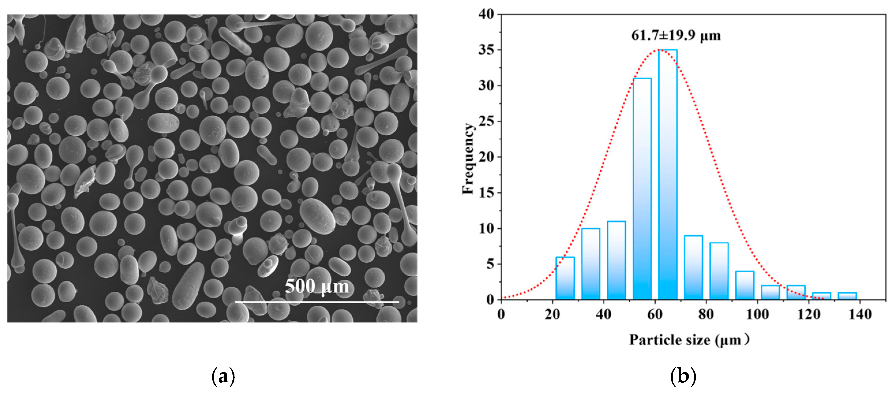
Figure 1. Microscopic examination and size characterization of FeCoNiCrAl HEA powder: (a) SEM image and (b) particle size information.
Coatings 15 00986 g001
Figure 2. Determination of the structural diffraction patterns of FeCoNiCrAl HEA coatings: (a) XRD pattern of as-sprayed and annealed coatings and (b) schematic diagram illustrating the effect of vacancy evolution on the phase structure of coatings at different temperatures.
Coatings 15 00986 g002
Figure 3. Electrochemical impedance spectroscopy analysis of sequentially prepared FeCoNiCrAl HEA coatings under different annealing treatment conditions: (a) overview of Nyquist plots; (b) magnified section of Nyquist plots; (c) phase angle as a function of frequency; (d) magnitude of impedance |Z| versus frequency; and (e) equivalent electrical simulation model.
Coatings 15 00986 g003
Figure 4. Analytical standardization with polar bubble charts derived from EIS data: (a) as-sprayed; (b) 400 °C; (c) 600 °C; and (d) 800 °C.
Coatings 15 00986 g004
Figure 5. Potentiodynamic polarization analysis of sequentially structured FeCoNiCrAl HEA coatings.
Coatings 15 00986 g005
Figure 6. Temperature-dependent growth behavior of passive film and double-layer capacitance thicknesses based on effective capacitance framework: (a) evolution of passive film thickness and (b) dimension of double-layer capacitance region.
Coatings 15 00986 g006
Figure 7. Schematic diagram of passive film and electrical double-layer structure along with ion exchange mechanism: (a) electron exchange in passive film; (b) counter-ion compensation in passive film.
Coatings 15 00986 g007
Figure 8. Mott–Schottky curves for sequentially prepared FeCoNiCrAl HEA coatings: (a) as-sprayed; (b) 400 °C; (c) 600 °C; and (d) 800 °C.
Coatings 15 00986 g008
Figure 9. Wear performance of sequentially prepared FeCoNiCrAl HEA coatings: (a) frictional coefficient curves and (b) average friction coefficients.
Coatings 15 00986 g009
Figure 10. Worn surfaces of as-sprayed coating: (a) wear scratch morphology; (bg) EDS mappings; and (h) visual presentation of the three-dimensional topographic data.
Coatings 15 00986 g010
Figure 11. Worn surfaces of coating annealed at 400 °C: (a) wear scratch morphology; (bg) EDS mappings; and (h) visual presentation of the three-dimensional topographic data.
Coatings 15 00986 g011
Figure 12. Worn surfaces of coating annealed at 600 °C: (a) wear scratch morphology; (bg) EDS mappings; and (h) visual presentation of the three-dimensional topographic data.
Coatings 15 00986 g012
Figure 13. Worn surfaces of coating annealed at 800 °C: (a) wear scratch morphology; (bg) EDS mappings; and (h) visual presentation of the three-dimensional topographic data.
Coatings 15 00986 g013
Figure 14. Schematic diagram illustrating the complementary effects of nitrogen and hydrogen heat treatments based on molecular orbital theory analysis [41].
Coatings 15 00986 g014
Figure 15. Schematic illustrations of coating passivation and electrochemical reaction processes based on the point defect model theory framework: (a) visualization of electrochemical reactions in the coating–passivation film–precipitated layer system based on the point defect model; (b) diagrams representing the interfacial potential drops (Um/f, Uf, and Uf/s represent the volage drop across coating/passive film interface, internal passive film, and passive film/outer layer, respectively; Uext stands for the total potential drop from the inside to the outside); and (c) PDM reactions.
Coatings 15 00986 g015
Figure 16. Schematic diagrams of wear model based on stress equilibrium and energy balance mechanisms: (a) uniform stress distribution and energy absorption via plastic deformation in coating system, and the regions I, II, and III represent the interfacial interaction zone, transitional deformation zone, and relatively stable zone of the coating under frictional load, respectively; (b) frictional-load-induced stress-compliant layer response in coating; (c) frictional load stress counterbalance by heat-treated layer in coating; and (d) frictional load energy balance exchange in coating under wear.
Coatings 15 00986 g016
Table 1. Customized parameters optimized for plasma spraying process.
Tailored ParametersInput Values
Supplied power (kW)46.1
Primary gas supply rate (L/min)45.4
Secondary gas supply rate (L/min)24.0
Carrier gas supply rate (L/min)7.5
Cross-traversal velocity (mm/s)140
Coating passes3
Table 2. Quantitative phase composition determination of XRD results via Rietveld refinement.
Temperature (°C)Phase Composition (wt.%)
α-FeAl0.9Ni4.22Fe0.64N0.36
2590.919.09/
40091.208.80/
60082.2717.73/
80044.54/55.46
Table 3. Simulated results derived from EIS data for sequentially prepared FeCoNiCrAl HEA coatings immersed in a 3.5 wt.% NaCl aqueous solution.
Temperature (°C)Rs
(Ω·cm2)
Qf
−1·cm−2·sn1)
Rf
(Ω·cm2)
n1df
(nm)
Qdl
−1·cm−2·sn2)
Rct
(Ω·cm2)
n2ddl
(nm)
2525.460.000196034150.781.350.000167627900.781.58
40018.880.000618018780.770.490.000792617410.740.59
60016.480.001082779.30.750.380.001041796.20.730.52
80023.510.000094380730.886.930.0000107919,1900.904.61
Table 4. Key electrochemical parameters for sequentially constructed FeCoNiCrAl HEA coatings in 3.5 wt.% NaCl electrolyte.
Temperature (°C)Ecorr
(mV)
Icorr
(μA·cm−2)
Epit
(mV)
Ipass
(μA·cm−2)
Rp
(Ω·cm2)
25−9759.7181.93803876
400−101812.6−53.52573008
600−10395.39−45.093.36782
800−9231.64−183.433.324,206
Table 5. Dopant and acceptor concentrations of sequentially prepared FeCoNiCrAl HEA coatings passivated in 3.5 wt.% NaCl solution.
Temperature (°C)Donor Density (cm−3)Acceptor Density (cm−3)
253.41 × 10202.13 × 1020
4001.08 × 10211.37 × 1021
6006.39 × 10216.56 × 1021
8009.86 × 10173.15 × 1018
Disclaimer/Publisher’s Note: The statements, opinions and data contained in all publications are solely those of the individual author(s) and contributor(s) and not of MDPI and/or the editor(s). MDPI and/or the editor(s) disclaim responsibility for any injury to people or property resulting from any ideas, methods, instructions or products referred to in the content.