Article

Significantly Improved Protection Performance of Lotus-Leaf-Extract-Modified Mortar Against Chloride Corrosion

1
Yancheng Port and Shipping Development Center, Yancheng 224000, China
2
College of Materials Science and Engineering, Hohai University, Changzhou 213200, China
3
Jiangsu Provincial Engineering Research Center for Structure-Function Integrated Metallic Materials for Harsh Environments, Hohai University, Changzhou 213200, China
*
Authors to whom correspondence should be addressed.
Coatings 2025, 15(9), 983; https://doi.org/10.3390/coatings15090983
Submission received: 23 July 2025 / Revised: 11 August 2025 / Accepted: 19 August 2025 / Published: 22 August 2025

Abstract

Reinforced concrete structures in harsh environments are highly vulnerable to structural damage caused by rebar corrosion. However, there remains a critical shortage of high-performance, environmentally friendly repair materials that integrate both structural restoration and long-term corrosion protection functionalities to address this issue. To meet this demand, this study innovatively developed an eco-friendly, high-performance repair material using lotus leaf extract (LLE)-modified mortar and systematically evaluated its corrosion protection performance and mechanisms under chloride attack conditions. The primary chemical constituents of LLE include alkaloids and flavonoids, rich in polar functional groups such as O–H, N–H, and C–O. The LLE modifier increased the fluidity of fresh cement paste, thereby improving its construction workability. A low dosage of LLE modifier promoted cement hydration. When the LLE dosage was 0.2 wt%, the 7-day and 28-day flexural strengths of the LLE-modified mortar increased by 16.8% and 7.48%, respectively, compared to those of unmodified mortar, while the compressive strengths increased by 30.6% and 14.5%, respectively. The LLE-modified mortar demonstrated significant protection against chloride corrosion, effectively inhibiting rebar corrosion. Electrochemical corrosion results indicated that compared to unmodified mortar, the modified mortar containing 0.5 wt% LLE exhibited an 80% improvement in protection efficiency against chloride corrosion. These results demonstrate that an appropriate dosage of LLE modifier can simultaneously optimize the fundamental properties of mortar and provide excellent chloride corrosion protection. Therefore, LLE-modified mortar shows promising application potential in integrated repair and corrosion protection engineering for reinforced concrete structures.

1. Introduction

In aquatic environments, particularly seawater containing chloride ions, reinforced concrete structures face significant risks of corrosion [1,2]. Chloride ion ingress induces rebar corrosion and subsequent expansion, readily leading to cracking and spalling of the concrete cover. This results in severe deterioration of structural durability and potentially catastrophic structural failure, posing a major threat to operational safety and service life [3,4,5,6,7]. Consequently, the timely repair of damaged concrete structures and the enhancement of the corrosion protection efficacy of the concrete cover are critically important for improving structural durability and ensuring service safety.
Concrete deterioration is often closely associated with reinforcement corrosion [8,9,10]. The increasing demand for repairing corrosion-induced damage in structural engineering has spurred the development of diverse technologies [11]. Among these, repair mortars are commonly employed for local patching or conventional repairs of structures. They can provide a certain degree of isolation for exposed rebar resulting from concrete cover spalling, shielding against corrosive agents [12]. However, although traditional repair mortars can partially impede water penetration to some extent, dissolved aggressive ions can still gradually penetrate through their hydrophilic capillary pores, eventually leading to rebar corrosion [13,14,15]. Therefore, endowing repair mortars with the functionality to suppress rebar corrosion, achieving an integrated repair and protective mortar, is of paramount significance for repairing corrosion-damaged structures and ensuring long-term protection.
To address the insufficient corrosion protection performance of conventional repair mortars, adjusting the binder composition and incorporating specific admixtures can modify the cement hydration reaction. This enhances the mortar’s densification and impermeability, thereby improving its corrosion protection efficacy [16,17,18,19]. Additionally, incorporating corrosion inhibitors as admixtures into the mortar is another effective strategy to enhance its protective performance. An ideal corrosion inhibitor should effectively suppress rebar corrosion while demonstrating good compatibility with concrete, without adversely affecting its workability or mechanical properties [20]. Nonetheless, despite their effectiveness, traditional inhibitors such as nitrites and molybdates face environmental concerns and material compatibility issues, driving the need to develop environmentally friendly, high-performance alternatives [21,22,23].
Recent years have witnessed growing research interest in eco-friendly corrosion inhibitors for rebar in cementitious environments (mortar/concrete), with most extracts derived from plant leaves [24,25]. While these botanical inhibitors exhibit measurable protective effects [26], their corrosion inhibition efficiency requires further enhancement. Moreover, their anti-corrosion performance under realistic concrete service conditions (beyond laboratory simulations) necessitates thorough validation.
Lotus is a widely distributed plant used for both medicinal and edible purposes. Lotus leaf extract (LLE), a natural compound extracted from lotus leaves, finds broad applications in healthcare and medicine while also exhibiting potential in the field of metal corrosion protection [27,28]. Recent studies indicate that LLE possesses promising corrosion inhibition performance [29,30,31,32]. Rich in polar functional groups, LLE can adsorb and form protective films on the rebar surface, demonstrating its potential as a high-efficiency corrosion inhibitor for rebar. Previous research by our group systematically investigated the influence of LLE on the corrosion behavior of rebar and its inhibition mechanism in various environments, such as 3.5% NaCl solution and simulated concrete pore solution [33]. However, the practical applicability and long-term protective efficacy of LLE within actual cementitious material systems (e.g., mortar, concrete) still require in-depth validation.
In light of this, this study innovatively incorporates LLE internally within mortar to develop a modified mortar possessing integrated repair and protection capabilities. By leveraging the synergistic effect between the green botanical inhibitor and the repair material, this approach significantly enhances the mortar’s corrosion protection performance. Consequently, it provides a novel pathway for the repair and long-life service of reinforced concrete structures operating in harsh environments.

2. Experimental

2.1. Raw Materials and Preparation Process for LLE-Modified Mortar

The cement used in this study was Conch P·O 42.5 ordinary Portland cement (produced by Conch Cement Co., Ltd. (Wuhu, China)), with its chemical composition detailed in Table 1. The fine aggregate adopted was ISO 679 standard sand (compliant with Chinese standard GB/T 17671). Clean tap water was used for all mortar experiments. The LLE modifier, commercially obtained as a standardized lotus leaf extract, was procured from Guosheng Biotechnology Co., Ltd. (Shanghai, China), a specialized supplier of botanical extracts for research applications.
The cement, sand, and water respectively constituted 25.64 wt%, 64.10 wt%, and 10.26 wt% of the total mortar mass. LLE-modified mortars were formulated by incorporating LLE at additive concentrations of 0, 0.1 wt%, 0.2 wt%, 0.3 wt%, 0.4 wt%, and 0.5 wt% of the mortar mass. By calculation, in the present study, a range of 0 wt% to 0.5 wt% of mortar mass is equivalent to 0 wt% to 1.95 wt% relative to the cement mass, which is a commonly used addition range for concrete admixtures in cement. Note that the LLE was first dissolved in water. The resulting LLE aqueous solution was then mixed with cement and sand to form the fresh mixture, which was subsequently cast into specimens of LLE-modified mortar. Specimens were cast into molds under vibration compaction, then cured in a controlled chamber (20 ± 2 °C, RH > 95%). Mortars with varying LLE contents were designated as original, 0.1% LLE-modified, 0.2% LLE-modified, 0.3% LLE-modified, 0.4% LLE-modified, and 0.5% LLE-modified mortar.
It has to be noted that, in the present study, the fluidity test specimen was exclusively cement paste (without sand), while all other tests and investigations were conducted on mortar.

2.2. Mechanical Property Testing of LLE-Modified Mortar

Flexural and compressive strength tests followed the ISO 679 standard of testing cements—determination of strength (equivalent to Chinese standard GB/T 17671). Specimens (40 mm × 40 mm × 160 mm) were tested at 7-day and 28-day curing ages. The loading rates were set to 5000 N/s for flexural strength and 2400 N/s for compressive strength. In each series, more than three samples were tested.

2.3. Microstructural Characterization of LLE Modifier and LLE-Modified Mortar

Scanning Electron Microscopy (SEM): Morphological features of LLE and hydration products in LLE-modified mortar were examined using a Gemini SEM 300 (ZEISS, Oberkochen, Germany). Samples were gold-sputtered prior to imaging to ensure conductivity.
Fourier Transform Infrared Spectroscopy (FTIR): Functional groups/molecular structure of LLE and hydrate compositions were analyzed using a Nicolet iS20 FTIR spectrometer (Thermo Scientific, Waltham, MA, USA). Dried samples were finely ground and pelletized before testing.

2.4. Corrosion Protection Performance Evaluation of LLE-Modified Mortar

Corrosion resistance was assessed using electrochemical testing combined with X-ray computed tomography (X-CT) analysis of corrosion products after full immersion in 3.5 wt% NaCl solution.

2.4.1. Electrochemical Corrosion Testing

HRB400 carbon-steel rebar (Ø16 mm; chemical composition in Table 2) was selected as the target rebar and cut to 80 mm lengths. The surface treatment involved sandblasting, rust removal using inhibitors, degreasing with acetone, ultrasonic cleaning in ethanol, and drying. A 20 mm segment of rebar at one end was reserved for electrical connection. Copper wires were soldered to this segment and reinforced with conductive epoxy. Electrodes were stored in a desiccator before use. The active exposure length of the tested rebar was about 60 mm with a surface area of 30.16 cm2. The specimen casting was conducted as follows. Rebar electrodes were centrally positioned in cylindrical plastic molds (Ø50 × 100 mm), then the LLE-modified mortar was poured around the rebar and compacted by vibration. The rebar–mortar samples were cured after demolding after 24 h, followed by sealing of both ends with epoxy resin and standard curing for 28 days.
Electrochemical measurements were conducted using a CHI600E electrochemical workstation (CH Instruments, Shanghai, China) employing a three-electrode system: a rebar–mortar sample serving as the working electrode (WE), a saturated calomel electrode (SCE) as the reference electrode (RE), and a tubular counter electrode (CE) fabricated from 304 stainless steel sheet. To minimize solution resistance effects, the RE was positioned in close proximity to the rebar while the CE concentrically surrounded the specimen. All tests were performed at 25 ± 2 °C with three samples ensuring reproducibility. Corrosion protection performance was evaluated via electrochemical impedance spectroscopy (EIS) and potentiodynamic polarization (PDP). EIS measurements, initiated at open circuit potential (OCP), applied a sinusoidal signal (±5 mV amplitude) across a frequency range of 100 kHz to 10 mHz; acquired spectra were fitted using ZSimpWin software. PDP tests involved voltage sweeps from OCP −0.25 V to +1.0 V at 1 mV/s, with the corrosion current density (icorr) determined through Tafel extrapolation.

2.4.2. X-CT Tomography for Corrosion Characterization

X-ray computed tomography (X-CT), a non-destructive imaging technique, was utilized to analyze the corrosion morphology of rebar–mortar specimens after 90 days of immersion in 3.5 wt% NaCl solution. This method generates 3D reconstructions by acquiring sequential 2D tomographic slices based on differential X-ray absorption through heterogeneous materials. Specimens were scanned using a Y.CT PRECISION industrial CT (YXLON, Hamburg, Germany) system operated at 195 kV and 0.22 mA. The volumetric data reconstruction and quantitative analysis of corrosion products (morphology/distribution) and rust-induced cracking were performed with VGStudioMax 3.0 software, enabling spatial mapping of degradation features.

3. Results and Discussion

3.1. Morphological and Compositional Analysis of LLE

The morphology and elemental composition of the raw LLE modifier were characterized using scanning electron microscopy (SEM) coupled with energy-dispersive X-ray spectroscopy (EDS). As depicted in Figure 1a,b, the LLE comprises irregularly spherical particles with diameters ranging from 6 to 60 μm. While most particles exhibit favorable sphericity, their surface topography varies between smooth and concave textures. Notably, the particles display a heterogeneous dispersion with a propensity for agglomeration among varying diameters, and fine particles are observed adhering to larger ones. EDS mapping analysis (Figure 1c) confirmed that LLE predominantly consists of carbon (C) and oxygen (O), with trace amounts of potassium (K), chlorine (Cl), magnesium (Mg), sodium (Na), and calcium (Ca). Note that hydrogen (H) is the essential element in biomass materials but cannot be detected by EDS due to its low atomic mass.
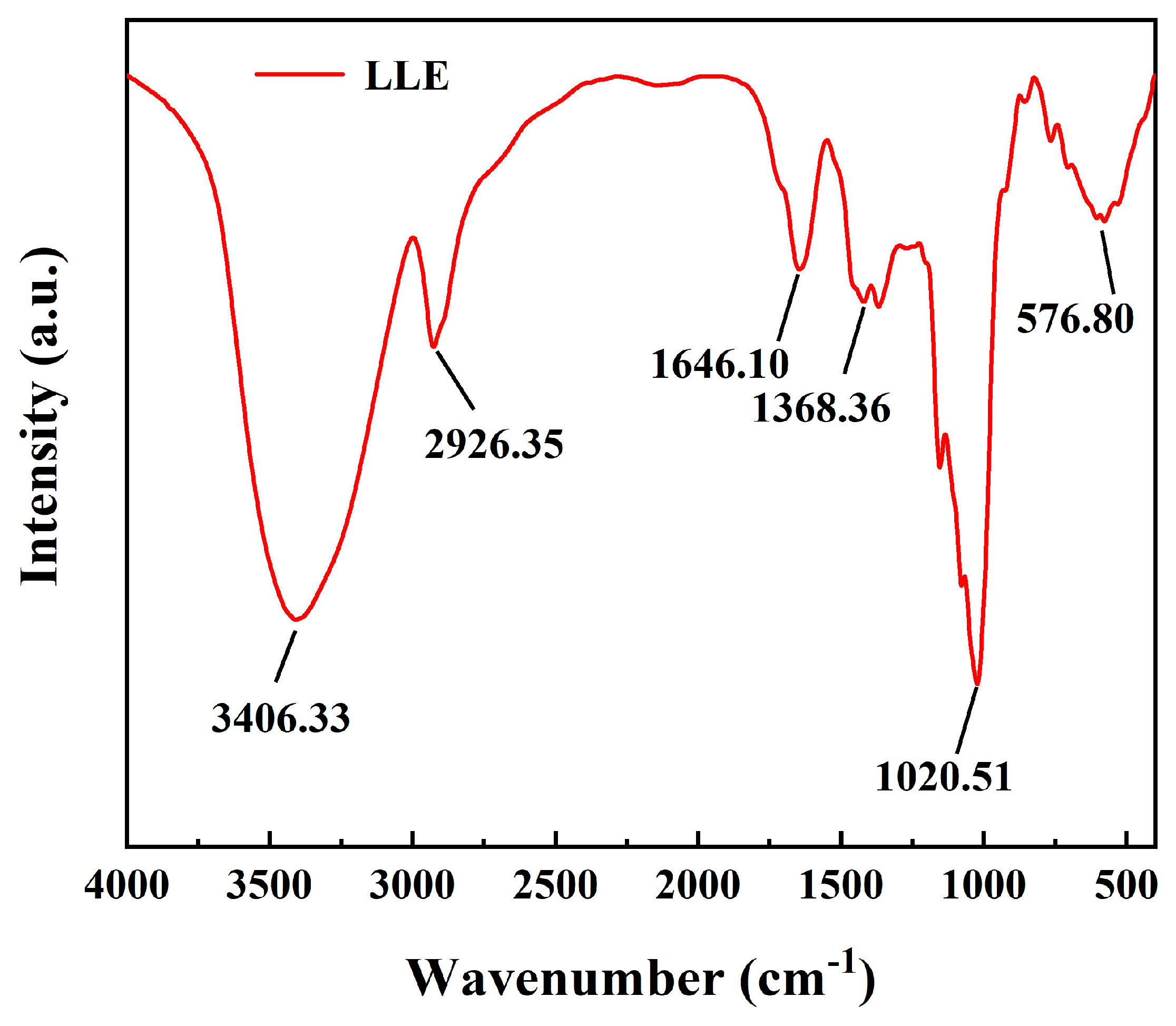
The molecular architecture and chemical constituents of the LLE were characterized through integrated Fourier transform infrared spectroscopy (FTIR). FTIR spectral analysis (Figure 2) identified dominant functional groups: a strong C–O stretching vibration at 1026 cm−1, alkane C–H bending at 1368 cm−1, coupled N–H stretching and C=O carbonyl stretching vibrations at 1646 cm−1, saturated C-H stretching at 2926 cm−1, and broad O–H stretching from adsorbed water at 3406 cm−1. These spectral signatures confirm the abundance of hydroxyl (–OH), amine (–NH), and carboxyl/ether (C–O) moieties in LLE.
Relevant studies have demonstrated that the primary chemical constituents of LLE include alkaloids and flavonoids [27,33,34], such as C18H19NO2, C15H10O7, C21H20O12, and C15H10O6. The analytical results obtained in this study are consistent with these findings. This indicates that the chemical composition of the extract contains heteroatoms (e.g., N, O) and heterocyclic structures, which can serve as adsorption centers. The lone-pair electrons of these heteroatoms can chelate with the 3d empty orbitals of iron atoms, forming an adsorption film on the steel surface.

3.2. Effect of LLE Modifier on Cement Paste Fluidity

Fluidity, a key indicator of workability, was evaluated for cement paste incorporating LLE. Specimens were prepared at a water-to-cement ratio of 1:3 with varying LLE addition levels (0–0.5 wt%).
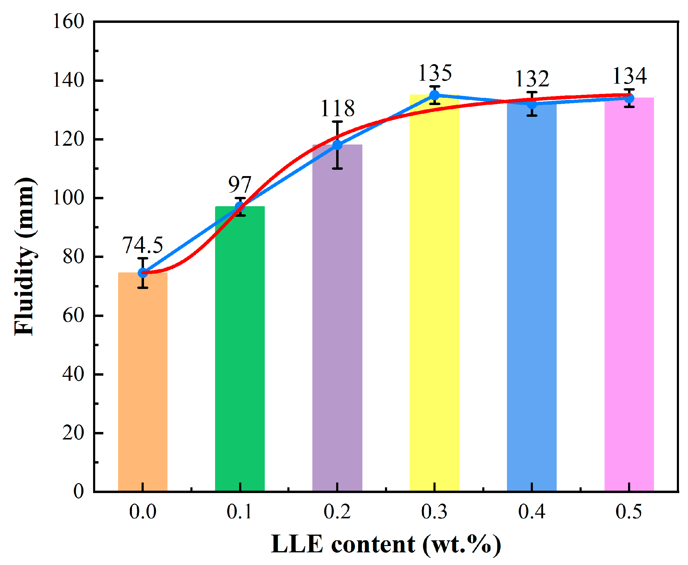
Figure 3 presents the fluidity of cement paste incorporating different concentrations of LLE. Note that the blue curve represents the variation in cement paste with the amount of LLE, while the red curve shows the statistically fitted trend of flow variation with the amount of LLE. Clearly, the fluidity increased progressively with the LLE dosage, peaking at 0.3 wt% with an 81.2% enhancement over the unmodified cement paste. This improvement is attributed to dissociated anionic functional groups (e.g., hydroxyl, carbonyl) in the LLE adsorbing onto cement particles. The resulting electrostatic repulsion promotes particle dispersion, releasing immobilized water and increasing fluidity. Beyond the optimal dosage of 0.3 wt%, further LLE addition ceases to enhance fluidity. The improved fluidity of cement paste with LLE facilitates superior workability in repair mortars, promoting construction expedience. However, this benefit carries a trade-off: prolonged cement setting and hardening times.

3.3. Effect of LLE Modifier on Mortar Mechanical Properties

Corrosion inhibitors must protect embedded reinforcements while maintaining cementitious compatibility; thus, assessing LLE’s impact on mechanical performance is critical for engineering applications. Flexural and compressive strength tests at 7-day and 28-day curing ages revealed dose-dependent responses.
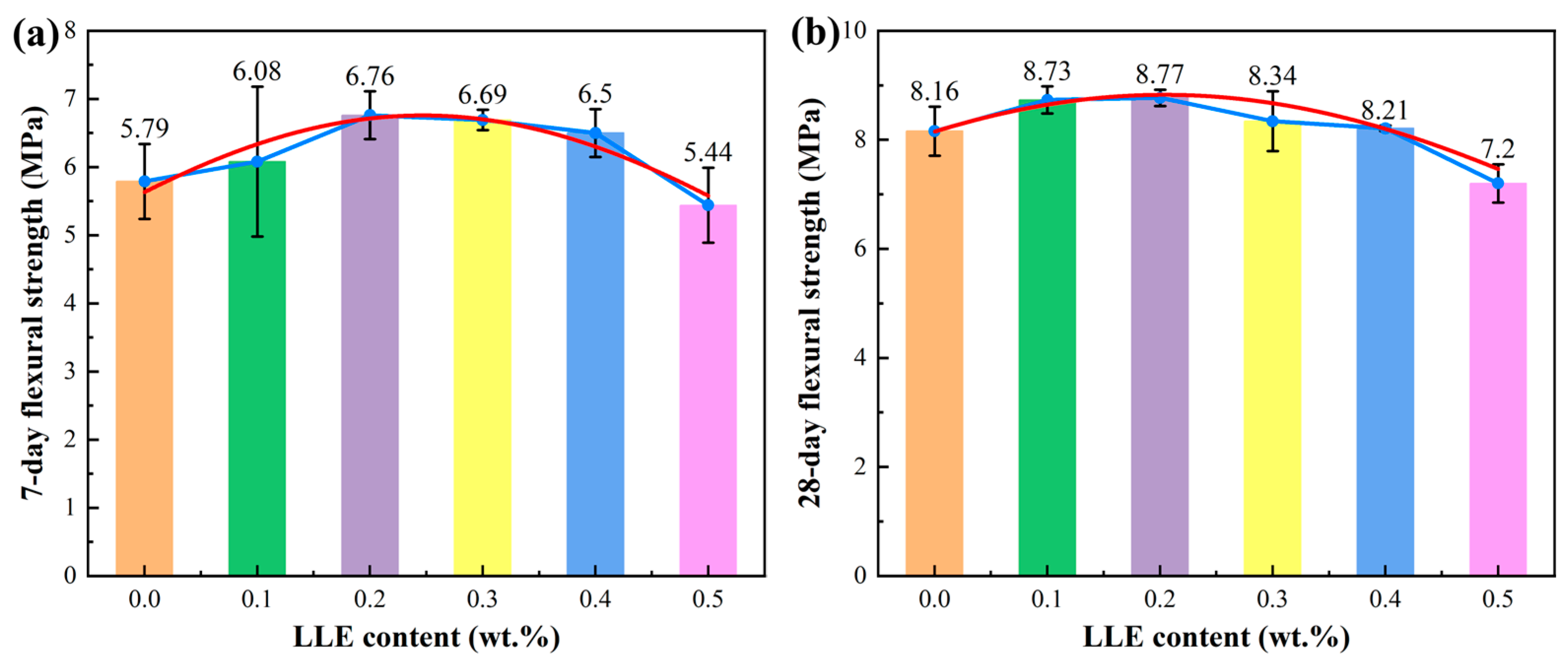
Figure 4 presents the flexural strength of mortar incorporating different concentrations of LLE. Note that the blue curve represents the variation in the flexural strength of mortar with the amount of LLE, while the red curve shows the statistically fitted trend of variation with the amount of LLE. At 7 days (Figure 4a), the flexural strength increased maximally at 0.2 wt% LLE (+16.8%, +1.0 MPa versus control) due to hydration acceleration from polar functional groups but declined at 0.5 wt% to control levels (±0.2 MPa), indicating hydration inhibition. By 28 days (Figure 4b), the optimal dose (0.2 wt%) sustained significant enhancement (8.77 MPa, +7.48%), while higher concentrations (>0.3 wt%) reduced strength, owing to suppressed hydration degrees.
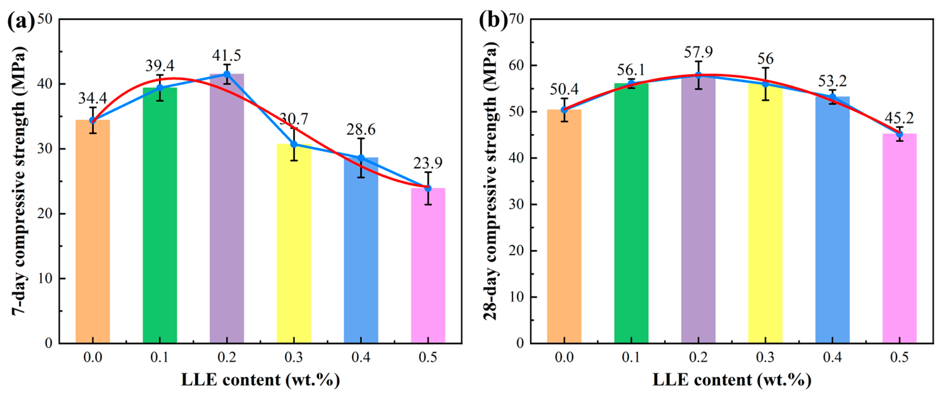
Figure 5 presents the compressive strength of mortar incorporating different concentrations of LLE. Note that the blue curve represents the variation in the compressive strength of mortar with the amount of LLE, while the red curve shows the statistically fitted trend of variation with the amount of LLE. Similarly, the compressive strength at 7 days (Figure 5a) peaked at 0.2 wt% LLE (+20.64%, +7.1 MPa) through densification via ionic/coordination bonding between LLE’s functional groups (–OH hydrogen-bonding with silicate tetrahedra; –COO chelating Ca2+) and hydration products. Concentrations above 0.3 wt% reduced strength by 12–15% by adsorbing onto cement particles and hindering hydration. After 28 days of curing (Figure 5b), all specimens regained strength yet retained dosage dependency, with 0.1–0.3 wt% LLE improving long-term performance without impeding hydration kinetics.

3.4. Influence of LLE Modifier on Cement Hydration Reactions

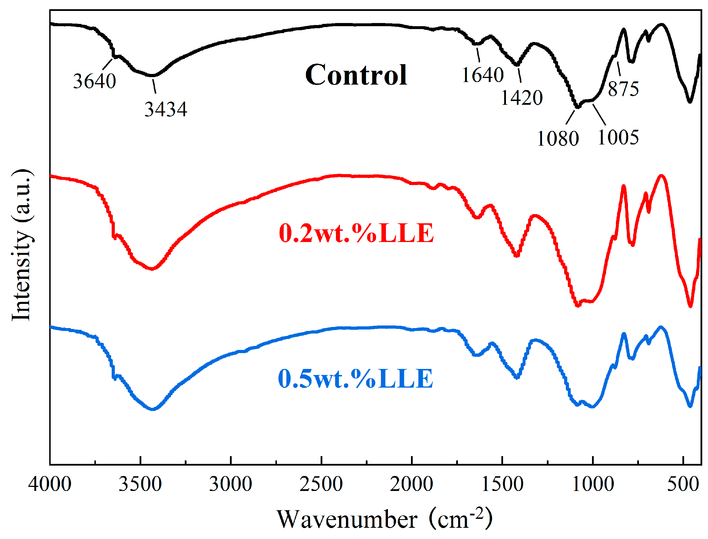
Cement hydration products critically govern mortar performance, necessitating a systematic investigation of LLE’s effects to elucidate its service behavior impacts. FTIR spectra of 28-day cured mortars (Figure 6) with 0.2 wt% and 0.5 wt% LLE versus an unmodified control revealed identical characteristic peaks—confirming unaltered hydration product types—yet exhibited dose-dependent intensity variations: the 3434 cm−1 band (O-H stretching in Calcium Silicate Hydrate (C–S–H) adsorbed water), 3640 cm−1 peak (portlandite [35]), 1420/875 cm−1 carbonate groups (atmospheric CO2 carbonation), 1645 cm−1 H-O-H bending (interlayer water), 980 cm−1 tetrahedral SiO4 (C–S–H), and 1118 cm−1 sulfate band (ettringite v3 SO4 [36]) initially intensify at 0.2 wt% LLE, indicating hydration acceleration, but diminish at 0.5 wt% LLE, demonstrating hydration inhibition through disrupted reaction kinetics. This establishes that low LLE concentrations (≤0.2 wt%) enhance cement hydration, whereas higher doses (≥0.5 wt%) impede critical reactions.

3.5. SEM Surface Morphology Analysis of LLE-Modified Mortar

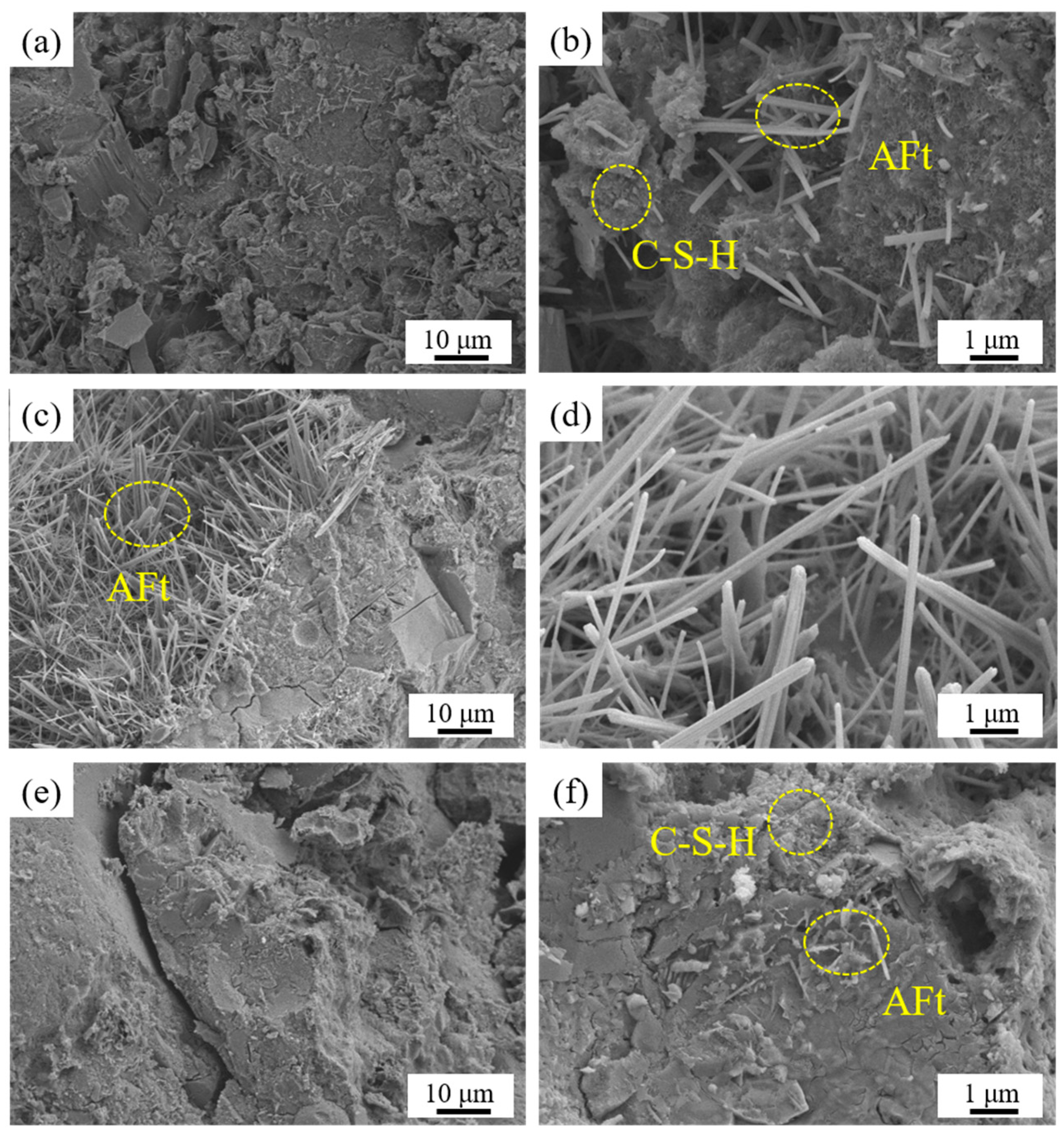
Figure 7 compares the SEM surface morphology of unmodified mortar with those of 0.2 wt% and 0.5 wt% LLE-modified specimens at 7 days of curing. Unmodified mortar (Figure 7a,b) displays honeycomb-patterned C–S–H gel dominating cement particle surfaces, with ettringite (Alumina–Ferric oxide–tri-sulfate; Aft; Ca6Al2(SO4)3(OH)12·26H2O) needles interspersed. At 0.2 wt% LLE (Figure 7c,d), dense C–S–H coexists with abundant needle-shaped ettringite crystals, where C–S–H provides primary strength support while high-hardness ettringite fills pores to enhance densification and early strength; concurrently, ettringite’s water-insoluble nature forms protective films around clinker grains, retarding hydration and explaining the prolonged setting times observed in Section 3.2. Conversely, 0.5 wt% LLE specimens (Figure 7e,f) exhibit flocculent C–S–H with increased porosity and partially reacted ettringite on unhydrated cement, attributable to LLE molecular adsorption reducing effective cement–water contact, thereby slowing mineral dissolution kinetics, extending the hydration induction period, and causing a >20% early-strength reduction.
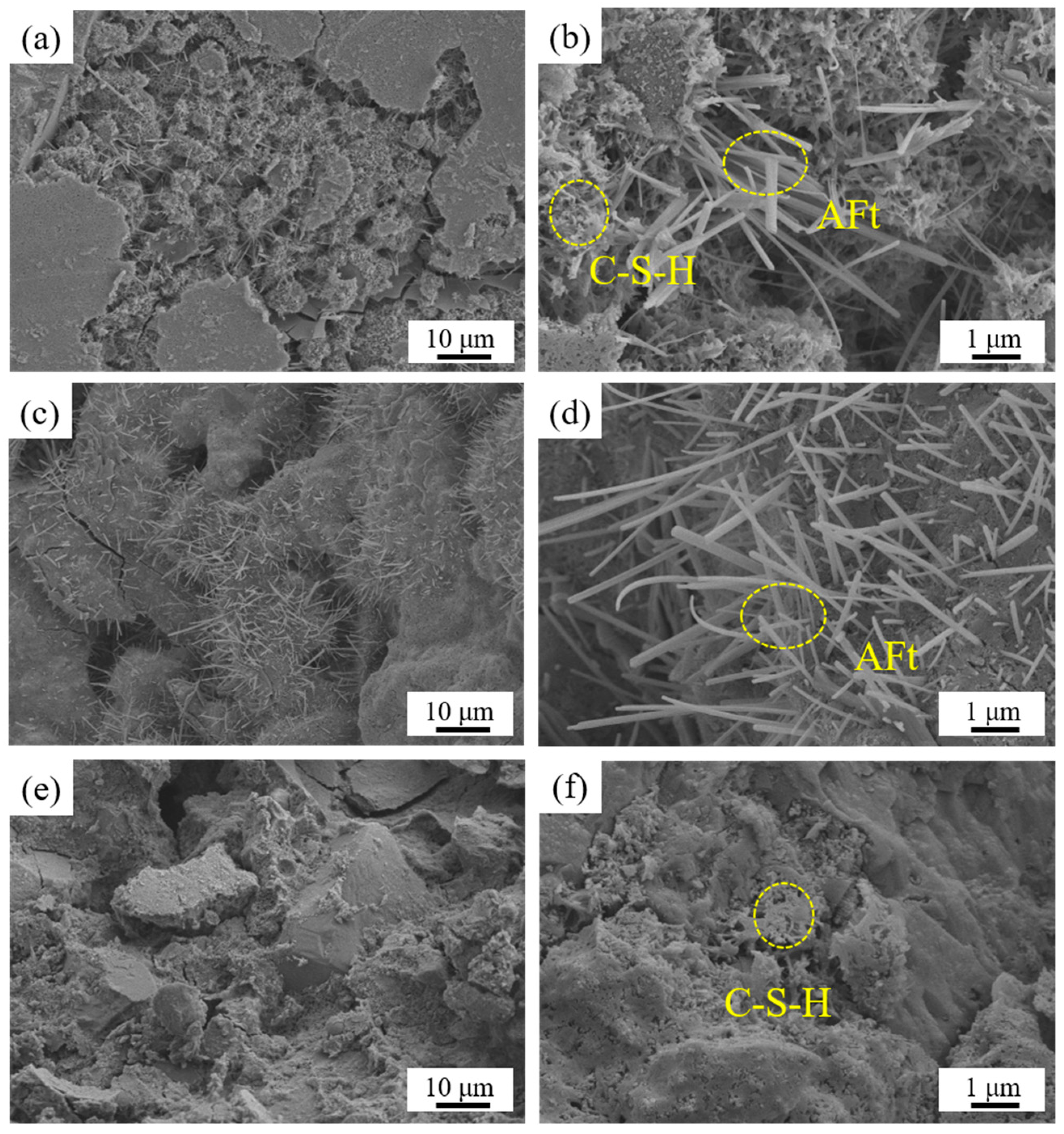
An analysis of 28-day hydration products (Figure 8) revealed progressive densification versus 7-day specimens. Control specimens exhibited dense C–S–H gel networks interspersed with robustly crystalline ettringite. In 0.2 wt% LLE mortar, intensified hydration yields greater quantities of intergrown C–S–H and ettringite, where the web-like C–S–H framework provides structural integrity while ettringite infills capillary pores; this synergistic encapsulation generates a consolidated matrix with enhanced mechanical performance. Conversely, 0.5 wt% LLE specimens develop discontinuous hydration phases characterized by stubby, underdeveloped ettringite crystals embedded within porous C–S–H networks. Critically, transversing microcracks propagate throughout this defective structure, directly accounting for the diminished mechanical properties observed at elevated LLE concentrations.
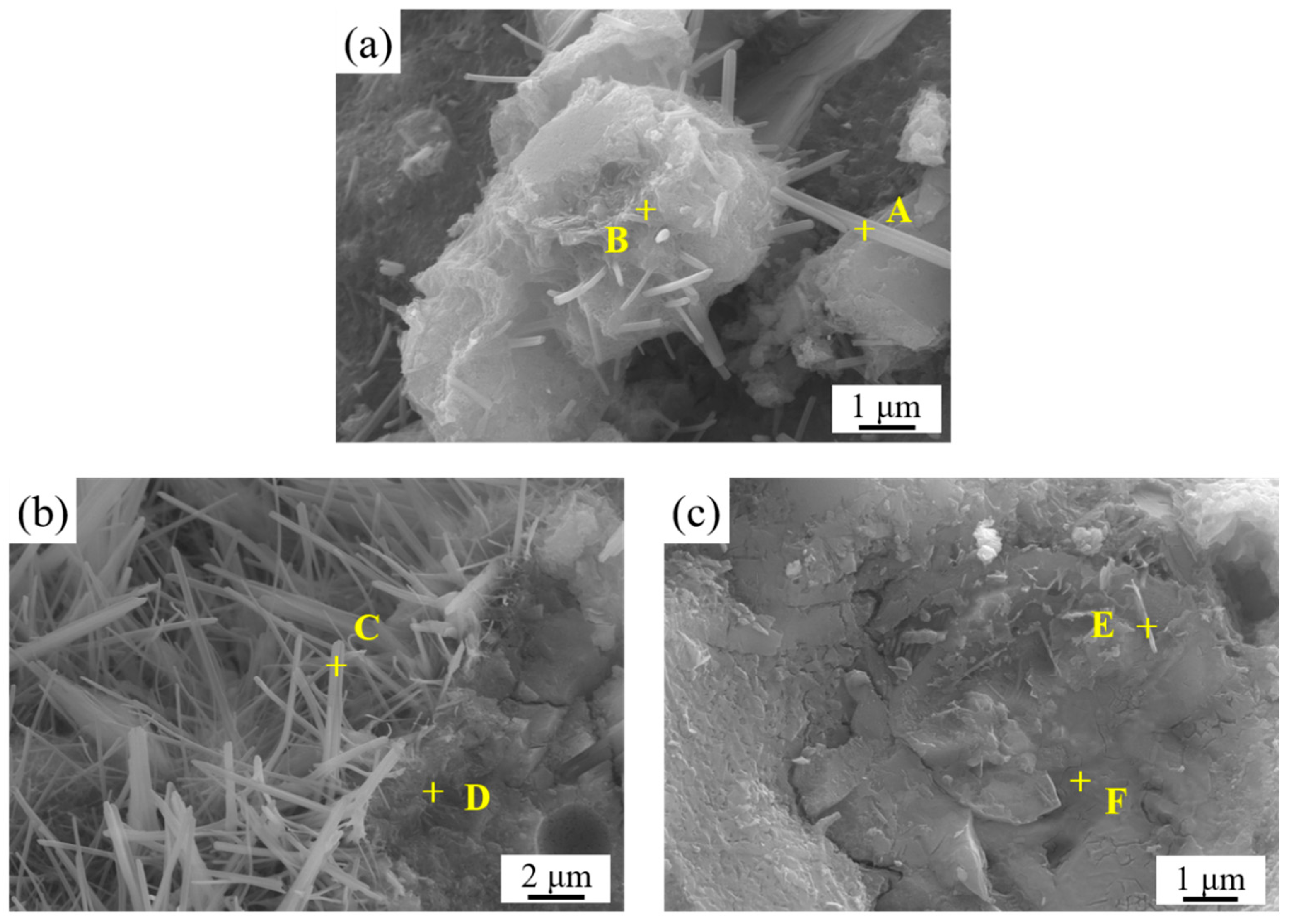
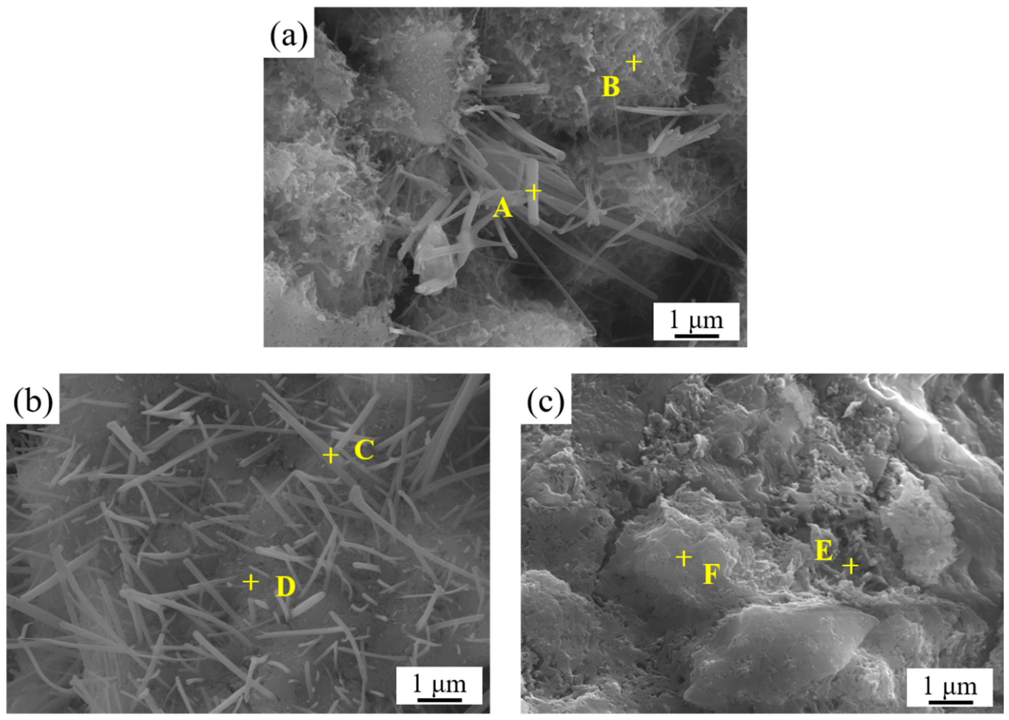
Figure 9 and Table 3 present SEM surface morphologies and EDS compositional analyses for LLE-modified mortars at various dosages after 7 days of curing. The elemental ratios at characteristic points demonstrate hydration disruption at 0.5 wt% LLE: location A yields Ca:Al:S ≈ 7.8:2.2:1, location C shows 5.3:1.2:1, and location E exhibits 16.5:4.3:1—significant deviations from stoichiometric ettringite (6:1:3) and C–S–H phases. The Ca/Si ratio escalates progressively with the LLE concentration: moderate increases at location D enhance mechanical strength through optimal polymer condensation [37], whereas an abnormal Ca/Si surge at location F indicates disrupted C–S–H gel formation under 0.5 wt% LLE, directly contributing to compromised early-age strength performance.
Figure 10 and Table 4 present SEM surface morphologies and EDS elemental analyses for LLE-modified mortars after 28 days of curing. Key compositional ratios reveal impaired ettringite crystallization at elevated LLE dosages: location A exhibits Ca:Al:S ≈ 8.5:1.3:1, location C shows 11.7:1.4:1, and location E registers 6:1.1:1—deviating significantly from stoichiometric ettringite (Ca6Al2(SO4)3(OH)12·26H2O). Concurrently, the Ca/Si ratios at locations D and F demonstrate an inverse correlation with the LLE concentration, decreasing progressively as the modifier dosage increases.

3.6. Chloride Corrosion Protection Performance via Electrochemical Analysis

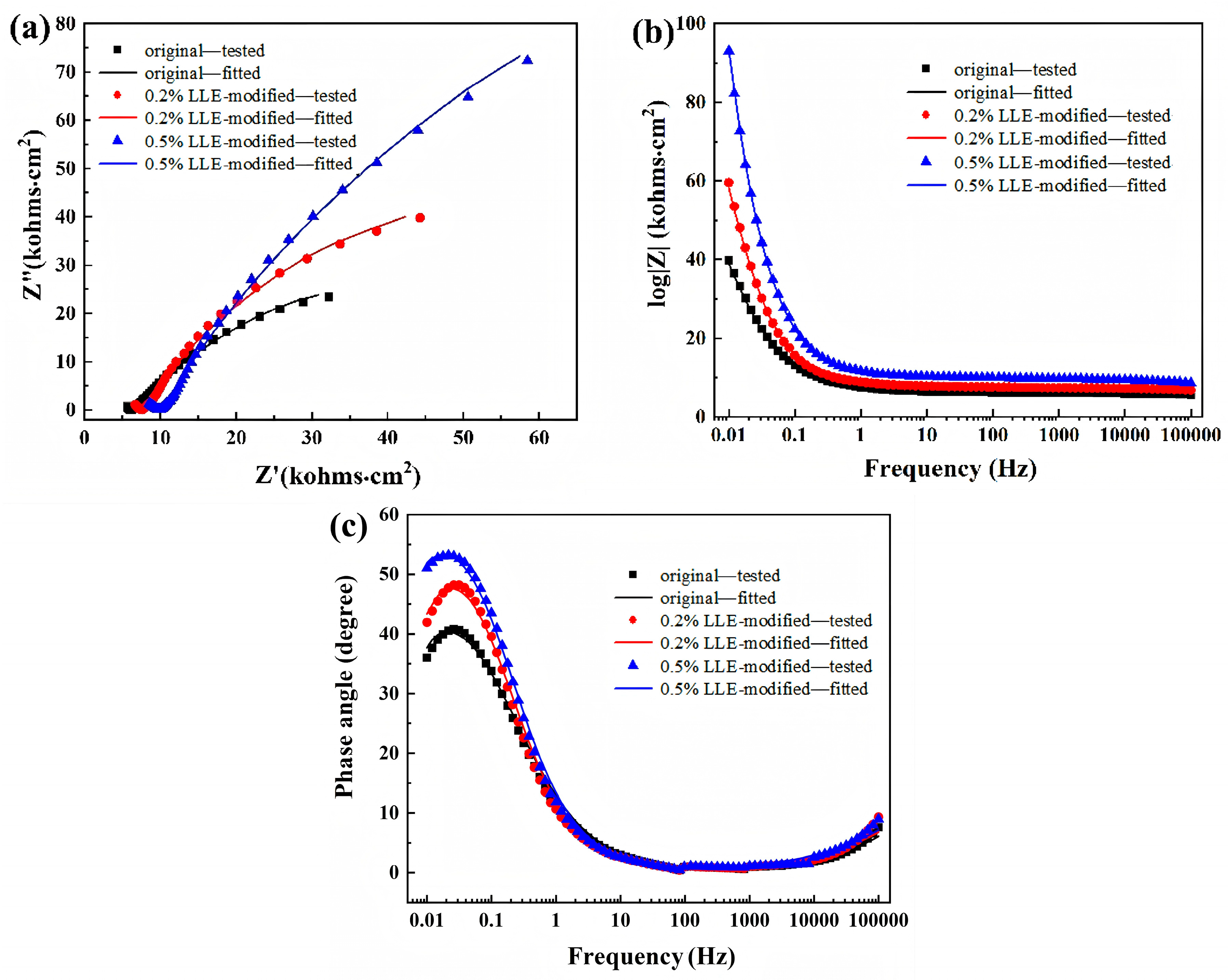
The electrochemical impedance spectroscopy (EIS) Nyquist plots for rebar–mortar specimens immersed in 3.5 wt% NaCl solution (Figure 11a) display two capacitive arcs: the high-frequency arc reflects mortar cover resistance, while the low-frequency arc represents charge transfer resistance at the rebar interface. Increasing the LLE concentration shifts the spectra rightward, indicating enhanced impedance. Larger capacitive arc radii correlate with superior protection. The addition of 0.2 wt% LLE significantly improves the corrosion resistance over that of unmodified mortar, while 0.5 wt% LLE further elevates protective efficacy. Correspondingly, the impedance modulus |Z| and phase angles (≤54°) increase with the LLE dosage, implying enlarged double-layer charge transfer resistance and continuous protective films that limit chloride exposure.
The equivalent circuit Rs(Qf(Rf(QdlRct))) models the electrochemical response: Rs denotes solution resistance; Rf represents mortar barrier resistance; Rct corresponds to corrosion resistance at the rebar interface. The simulated parameters are listed in Table 5. Protection efficiency (η, Equation (1)) is calculated as
η = R c t R c t , 0 R c t
where Rct,0 and Rct are the charge transfer resistances of unmodified and LLE-modified systems, respectively [38,39]. As shown in Table 5, LLE incorporation reduces film capacitance while increasing Rct, reaching peak η = 71.13% at 0.5 wt% LLE. Alkaline cement conditions further promote passivation, establishing diffusion-controlled corrosion inhibition supported by increasing n values indicating surface homogeneity improvement.
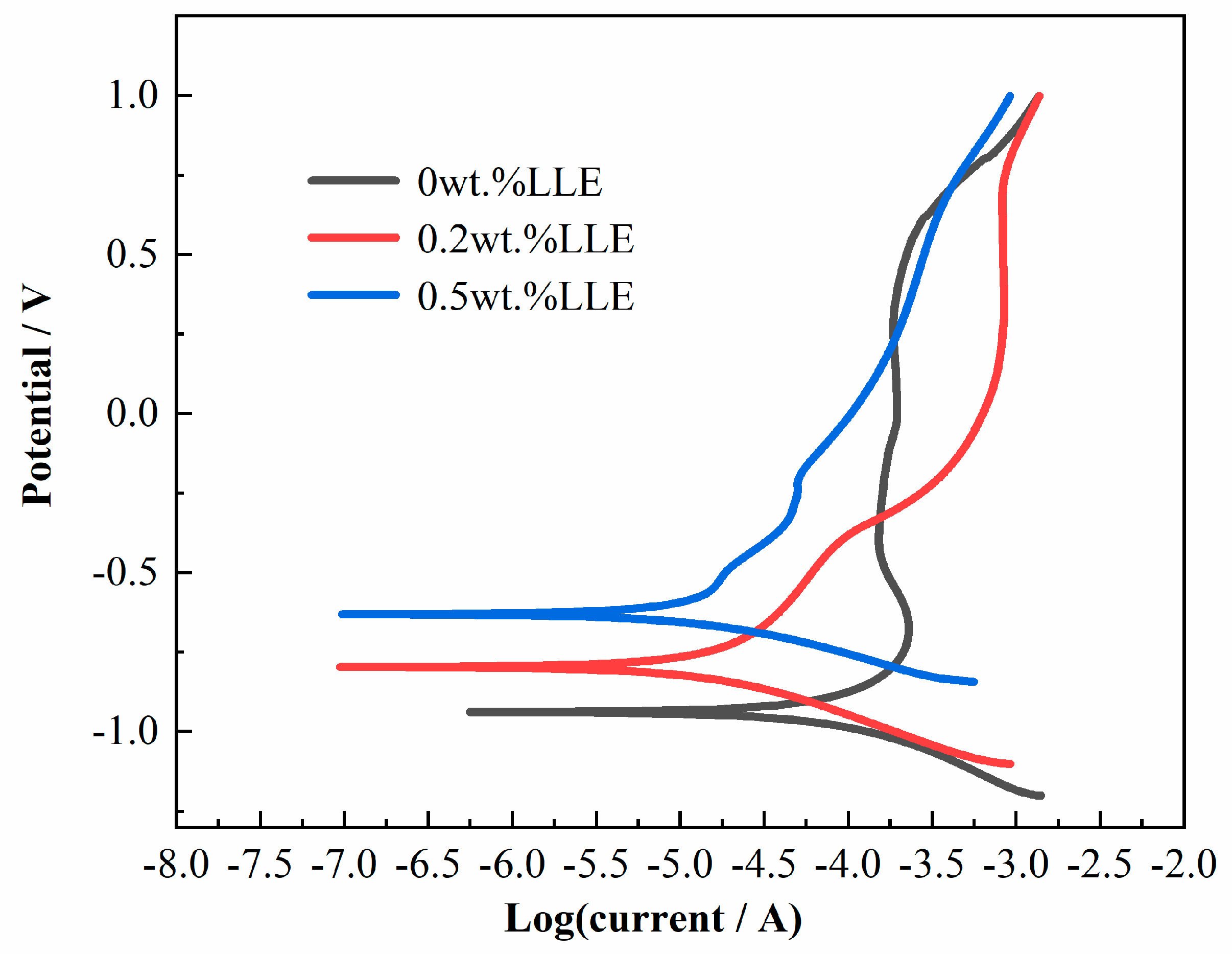
The potentiodynamic polarization results after 45 days of immersion (Figure 12 and Table 6) demonstrate that LLE-modified mortar provides effective corrosion protection for rebar, with protection efficiency exceeding 79% at optimal dosages (0.2 and 0.5 wt% LLE). The corrosion current density (icorr) decreases significantly to 5.6 × 10⁻⁷ A/cm2 (0.2 wt%) and 5.3 × 10⁻⁷ A/cm2 (0.5 wt%), while the corrosion potential (Ecorr) shifts positively versus the control sample. These electrochemical parameters confirm that LLE forms dense protective films at the mortar–rebar interface, effectively isolating the rebar from chloride ions and substantially inhibiting corrosion kinetics. The dose-dependent performance enhancement highlights LLE’s dual functionality as both a kinetic inhibitor (reducing the corrosion rate) and a thermodynamic stabilizer (elevating the corrosion initiation threshold).
This study systematically compared the corrosion protection performance of LLE for rebar in concrete environments with that of other natural corrosion inhibitors reported in the literature (Table 7). Conventional corrosion inhibitor research primarily focuses on simulated alkaline concrete environments [24,26], where the inhibition efficiency typically ranges between 70 and 80%, while the actual performance in real concrete requires further validation. LLE demonstrated over 90% inhibition efficiency in simulated concrete environments [33] in our previous work, and our findings in this paper reveal that it achieves 80% efficiency in actual mortar, confirming its crucial role in ensuring the durability of reinforced concrete structures. Compared to other natural inhibitors, LLE possesses three distinct application advantages, its wide availability of raw materials, ease of procurement, and simple, mild extraction process combining notable cost-effectiveness with environmental friendliness, thus exhibiting strong application potential.

3.7. Corrosion Products and Distribution Characteristics of LLE-Modified Mortar–Rebar Specimens Based on X-CT Analysis

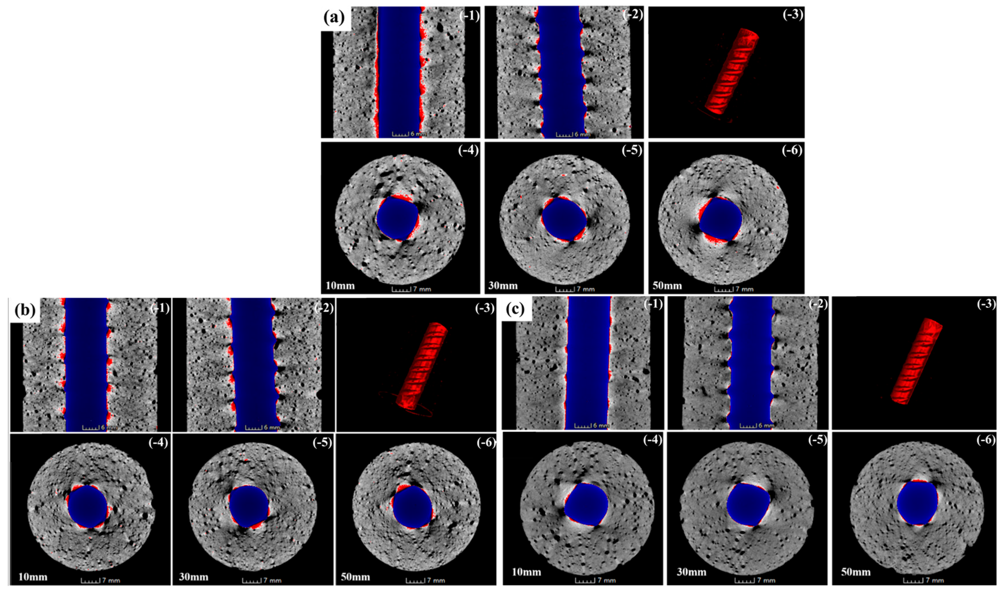
Based on the X-ray computed tomography (X-CT) of mortar–rebar specimens with and without LLE modifier after full immersion in 3.5 wt% NaCl solution for 90 days, as shown in Figure 13, distinct phases, including the embedded rebar, mortar matrix, and rebar corrosion products, could be clearly identified based on image grayscale values and were subsequently color-coded using software. In this representation, the pristine rebar substrate is depicted in blue, the rebar corrosion products are rendered in red, and the mortar matrix is shown in gray. It should be noted that in the test figures of samples with different LLE addition amounts, the overall labels a, b, etc., are marked in the upper left corner, and the sub labels -1, -2, -3, etc., are marked in the upper right corner. Below, a-1, a-2, etc., was used to represent each subgraph. Figure 13(a-1,a-2) visually demonstrate the distribution of corrosion products (red regions) within the mortar, revealing a substantial quantity adhered to the rebar surface, forming a distinct rust layer. The cross-sectional views presented in Figure 13(a-4–a-6) at heights of 10 mm, 30 mm, and 50 mm indicate similar corrosion patterns across the different heights of the rebar, consistent with a uniform corrosion morphology. Figure 13(a-3) illustrates the three-dimensional distribution of corrosion products within the mortar matrix, revealing a significant amount of corrosion products extensively disseminated from the interior to the exterior, indicating that the embedded rebar underwent relatively severe corrosion.
Figure 13b presents the X-CT scans of mortar–rebar specimens incorporating 0.2 wt% LLE modifier after 90 days of corrosion in 3.5% NaCl solution. Observations from the side view (Figure 13(b-1,b-2)) and cross-sections at varying heights (Figure 13(b-4–b-6)) reveal minimal corrosion product deposition on the rebar surface, primarily concentrated in threaded sections of the bar. This localized corrosion pattern is attributed to relatively weaker adsorption of modifier molecules on irregular surface geometries. The three-dimensional distribution of corrosion products (Figure 13(b-3)) further demonstrates limited diffusion of oxides within the mortar matrix, indicating significantly reduced corrosion compared to the control group and confirming the effective corrosion-inhibiting functionality of the LLE modifier in mortars.
Figure 13c displays X-CT results for specimens containing 0.5 wt% LLE. Analysis of the side view (Figure 13(c-1,c-2)) and multi-height cross-sections (Figure 13(c-4–c-6)) indicates trace amounts of corrosion products on the rebar surface. Crucially, Figure 13(c-3) shows virtually undetectable diffusion of corrosion products throughout the mortar matrix. This absence demonstrates superior adsorbed film formation by the high-concentration LLE modifier on the rebar surface, effectively isolating the substrate from chloride ions and suppressing corrosion initiation. These X-CT findings align closely with the electrochemical analysis data, jointly establishing a concentration-dependent enhancement in chloride-induced corrosion resistance and rebar protection efficacy in LLE-modified mortar systems.

3.8. Corrosion Protection Mechanism of LLE-Modified Mortar Against Chloride Corrosion

Figure 14 schematically illustrates the chloride corrosion protection mechanism of LLE-modified mortar. As depicted in Figure 14a, in a chloride-laden environment, chloride ions progressively diffuse inwards through the pore structure of an unmodified mortar protective layer. These ions eventually reach the mortar/rebar interface, adsorb onto the rebar surface, and attack the passive film. This leads to localized dissolution of the passive film, initiating corrosion of the underlying rebar substrate. Consequently, corrosion products accumulate at the mortar/rebar interface. The volumetric expansion associated with these corrosion products generates expansive stresses. These stresses induce mortar cracking, facilitating the direct ingress of aggressive media (like chlorides, oxygen, and moisture) along the cracks. This process significantly accelerates rebar corrosion.
In contrast, when LLE-modified mortar is employed, as shown in Figure 14b, the active components in LLE (e.g., flavonoids and alkaloids) undergo specific adsorption onto the iron atoms of rebar through their abundant polar functional groups (–OH, –NH2, C=O, etc.). The lone-pair electrons from these functional groups occupy the 3d empty orbitals of iron atoms, forming stable coordination bonds that construct a dense monomolecular protective film on the rebar surface. Furthermore, the planar conjugated structures of LLE molecules interact with the rebar surface via π-electron systems, creating a steric hindrance effect. The introduction of LLE significantly enhances charge transfer resistance (Rct), effectively inhibiting the electron transfer process in corrosion reactions. The adsorption film blocks the direct adsorption of chloride ions onto the rebar surface, thereby suppressing dissolution damage to the passive film by chlorides and delaying the initiation of rebar corrosion. This mechanism enables LLE-modified mortar to provide superior protection against chloride-induced corrosion for rebar.

4. Conclusions

The performance degradation of reinforced concrete structures caused by rebar corrosion in aggressive environments has emerged as a critical engineering challenge that demands urgent solutions. This study aimed to develop an environmentally friendly innovative technology that integrates both structural integrity restoration and durable corrosion protection capabilities. In this paper, an LLE-modified repair and protective mortar was developed, and the effects of the LLE modifier dosage on fundamental properties (including workability and mechanical strength) and chloride-induced corrosion resistance were systematically investigated. The influencing mechanisms of the LLE modifier on mortar microstructural evolution were elucidated. The key findings are summarized as follows:
(1) The LLE modifier enhanced the fluidity of fresh cement paste, improving its workability. Maximum paste fluidity occurred at an LLE dosage of 0.3 wt%. Lower LLE dosages (e.g., 0.2 wt%) increased both the flexural and compressive strength of mortar specimens. Compared to unmodified mortar, the incorporation of 0.2 wt% LLE elevated flexural strength by 16.8% and 7.48% at 7-day and 28-day curing ages, respectively, while compressive strength increased by 30.6% and 14.5%. Further increasing the LLE dosage detrimentally affected mechanical properties.
(2) The addition of 0.2 wt% LLE promoted cement hydration, whereas 0.5 wt% LLE partially inhibited hydration reactions, resulting in reduced formation of hydration products. Surface characterization confirmed that low-concentration LLE promoted the formation of increased C–S–H gel and moderate ettringite. Conversely, high-concentration LLE suppressed ettringite growth, yielding a more porous matrix with observable cracks.
(3) LLE-modified mortar exhibited significant chloride ingress mitigation and rebar corrosion inhibition. Electrochemical impedance spectroscopy (EIS) and potentiodynamic polarization (PDP) analyses demonstrated substantially enhanced chloride resistance upon the incorporation of 0.2 wt% LLE compared to unmodified mortar. The maximum chloride corrosion inhibition efficiency (74.75%–80%) was achieved at a 0.5 wt% LLE dosage. X-CT tomography confirmed that LLE markedly suppressed rebar corrosion, significantly reducing both the accumulation of corrosion products at the rebar–mortar interface and their diffusion into mortar pore structures.
(4) Mortars with low LLE dosages offered concurrently superior mechanical strength and chloride resistance compared to unmodified mortar, serving as promising candidates for structural repair applications requiring balanced performance. High-dosage LLE-modified mortar demonstrated exceptionally high chloride resistance but slightly compromised mechanical properties, making it suitable for structural protection in severely deteriorating service environments. In summary, through actual service conditions analysis and optimized dosage selection, an optimal balance between mechanical performance and corrosion protection can be achieved, thereby enabling high-performance structural integrity restoration coupled with long-term anti-corrosion capabilities.
It has to be noted that LLE, as a botanical extract, possesses inherent compositional complexity. Significant questions remain regarding its long-term service stability within concrete matrices, warranting further investigation. In addition, a detailed comparative analysis of the relative advantages and disadvantages of LLE and traditional commercial corrosion inhibitors is an important area of exploration. This includes key aspects such as cost-effectiveness in practical large-scale applications.

Author Contributions

Formal analysis, C.W. and Y.Z.; investigation, H.W. and G.W.; resources, Q.H.; experimental research, C.W., Y.Z., H.G., H.W. and G.W.; writing—original draft preparation, Q.H. and H.W.; writing—survey and editing, Q.H., S.Z. and D.S.; visualization, G.W.; supervision, Q.H. and D.S.; project administration, Q.H. and D.S.; funding acquisition, Q.H. and D.S. All authors have read and agreed to the published version of the manuscript.

Funding

This research was funded by Science and Technology Project of Jiangsu Provincial Department of Transportation (LSXGH-KT-SNJC) and National Natural Science Foundation of China (Grant Nos. 52278255, 51878246, and 52205208).

Institutional Review Board Statement

Not applicable.

Informed Consent Statement

Not applicable.

Data Availability Statement

Data are included in the article and the corresponding references.

Conflicts of Interest

Authors Changyun Wu, Yangshun Zhu, and Quan Hua were employed by Yancheng Port and Shipping Development Center. The remaining authors declare that the research was conducted in the absence of any commercial or financial relationships that could be construed as a potential conflict of interest.

References

  1. Roy, S.K.; Chye, L.K.; Northwood, D.O. Chloride ingress in concrete as measured by field exposure tests in the atmospheric, tidal and submerged zones of a tropical marine environment. Cem. Concr. Res. 1993, 23, 1289–1306. [Google Scholar] [CrossRef]
  2. Gao, Y.H.; Zheng, Y.Y.; Zhang, J.Z.; Wang, J.D.; Zhou, X.Y.; Zhang, Y.R. Randomness of critical chloride concentration of reinforcement corrosion in reinforced concrete flexural members in a tidal environment. Ocean Eng. 2019, 172, 330–341. [Google Scholar] [CrossRef]
  3. Angst, U.M. Challenges and opportunities in corrosion of steel in concrete. Mater. Struct. 2018, 51, 4. [Google Scholar] [CrossRef]
  4. Chen, D.; Mahadevan, S. Chloride-induced reinforcement corrosion and concrete cracking simulation. Cem. Concr. Compos. 2008, 30, 227–238. [Google Scholar] [CrossRef]
  5. Apostolopoulos, C.A.; Papadakis, V.G. Consequences of steel corrosion on the ductility properties of reinforcement bar. Constr. Build. Mater. 2008, 22, 2316–2324. [Google Scholar] [CrossRef]
  6. Tran, K.K.; Nakamura, H.; Kunieda, M.; Ueda, N. Three Dimensional Behaviour of Concrete Cracking Due to Rebar Corrosion. Procedia Eng. 2011, 14, 419–426. [Google Scholar] [CrossRef]
  7. James, A.; Bazarchi, E.; Chiniforush, A.A.; Aghdam, P.P.; Ghodoosi, F. Rebar corrosion detection, protection, and rehabilitation of reinforced concrete structures in coastal environments: A review. Constr. Build. Mater. 2019, 126, 1026–1039. [Google Scholar] [CrossRef]
  8. Ahmad, S. Reinforcement corrosion in concrete structures, its monitoring and service life prediction—A review. Cem. Concr. Compos. 2003, 25, 459–471. [Google Scholar] [CrossRef]
  9. Hu, J.Y.; Zhang, S.S.; Chen, E.; Li, W.G. A review on corrosion detection and protection of existing reinforced concrete (RC) structures. Constr. Build. Mater. 2022, 325, 126718. [Google Scholar] [CrossRef]
  10. Dinh, N.H.; Nguyen, C.V.; Bui, Q.H. Mechanical model for shear strength prediction of corrosion-damaged reinforced concrete beams under various corrosion schemes. Eng. Struct. 2025, 335, 120357. [Google Scholar] [CrossRef]
  11. Zhao, P.L.; Si, Z.; Huang, L.Z.; He, Y.L.; Liu, X.R.; Zhang, Y.L. A review of the repair measures for reinforced concrete affected by chloride ion corrosion. J. Build. Eng. 2025, 102, 112028. [Google Scholar] [CrossRef]
  12. Bielen, H.; Demet, L.; Audenaert, A.; Craeye, B. Behaviour of commercial cementitious repair mortars under various environmental conditions: A resistivity-based approach. Constr. Build. Mater. 2025, 472, 140929. [Google Scholar] [CrossRef]
  13. Zhou, P.; Zhu, Z.Y.; She, W. A superhydrophobic mortar with ultra-robustness for self-cleaning, anti-icing, and anti-corrosion. Chem. Eng. J. 2024, 495, 153488. [Google Scholar] [CrossRef]
  14. Nguyen, Q.D.; Castel, A. Long-term durability of underground reinforced concrete pipes in natural chloride and carbonation environments. Constr. Build. Mater. 2023, 394, 132230. [Google Scholar] [CrossRef]
  15. Xiong, Q.X.; Tong, L.Y.; Meftah, F.; Zhang, Y.; Liu, Q.F. Improved predictions of permeability properties in cement-based materials: A comparative study of pore size distribution-based models. Constr. Build. Mater. 2024, 411, 133927. [Google Scholar] [CrossRef]
  16. El Maaddawy, T.; Soudki, K. Carbon-Fiber-Reinforced Polymer Repair to Extend Service Life of Corroded Reinforced Concrete Beams. J. Compos. Constr. 2005, 9, 187–194. [Google Scholar] [CrossRef]
  17. Issa, C.A.; Assaad, J.J. Stability and bond properties of polymer-modified self-consolidating concrete for repair applications. Mater. Struct. 2017, 50, 28. [Google Scholar] [CrossRef]
  18. Sarde, B.; Patil, Y.D. Recent Research Status on Polymer Composite Used in Concrete-An Overview. Mater. Today Proc. 2019, 18, 3780–3790. [Google Scholar] [CrossRef]
  19. Mirza, J.; Mirza, M.S.; Lapointe, R. Laboratory and field performance of polymer-modified cement-based repair mortars in cold climates. Constr. Build. Mater. 2002, 16, 365–374. [Google Scholar] [CrossRef]
  20. Kobbekaduwa, D.; Nanayakkara, O.; Krevaikas, T.; Sarno, L.D. Effect of organic corrosion inhibitors on the behaviour of repair mortars and reinforcement corrosion. Constr. Build. Mater. 2024, 451, 138787. [Google Scholar] [CrossRef]
  21. Salleh, S.Z.; Yusoff, A.H.; Zakaria, S.K.; Taib, M.A.A.; Teo, P.T. Plant Extracts as Green Corrosion Inhibitor for Ferrous Metal Alloys: A Review. J. Clean. Prod. 2021, 304, 127030. [Google Scholar] [CrossRef]
  22. Berke, N.S.; Hicks, M.C. Predicting long-term durability of steel reinforced concrete with calcium nitrite corrosion inhibitor. Cem. Concr. Compos. 2004, 26, 191–198. [Google Scholar] [CrossRef]
  23. Shi, J.; Wu, M.; Ming, J. In-depth insight into the role of molybdate in corrosion resistance of reinforcing steel in chloride-contaminated mortars. Cem. Concr. Compos. 2022, 132, 104628. [Google Scholar] [CrossRef]
  24. Naderi, R.; Bautista, A.; Velasco, F.; Soleimani, M.; Pourfath. Green corrosion inhibition for carbon steel reinforcement in chloride-polluted simulated concrete pore solution using Urtica Dioica extract. J. Build. Eng. 2022, 58, 105055. [Google Scholar] [CrossRef]
  25. Liu, Q.; Song, Z.; Han, H.; Saddick, D.; Jiang, L.; Wang, W.; Chu, H. A novel green reinforcement corrosion inhibitor extracted from waste Platanus acerifolia leaves. Constr. Build. Mater. 2020, 260, 119695. [Google Scholar] [CrossRef]
  26. Anitha, R.; Chitra, S.; Hemapriya, V.; Chung, I.; Kim, S.; Prabakaran, M. Implications of eco-addition inhibitor to mitigate corrosion in reinforced steel embedded in concrete. Constr. Build. Mater. 2019, 213, 246–256. [Google Scholar] [CrossRef]
  27. Lee, K.S.; Kwon, Y.J.; Lee, K.Y. Analysis of Chemical Composition, Vitamin, Mineral and Antioxidative Effect of the Lotus Leaf. J. Korean Soc. Food Sci. Nutr. 2008, 37, 1622–1626. [Google Scholar] [CrossRef]
  28. Kashiwada, Y.; Aoshima, A.; Ikeshiro, Y.; Chen, Y.; Furukawa, H.; Itoigawa, M.; Fujioka, T.; Mihashi, K.; Cosentino, L.M.; Morris-Natschke, S.L.; et al. Anti-HIV benzylisoquinoline alkaloids and flavonoids from the leaves of Nelumbo nucifera, and structure–activity correlations with related alkaloids. Bioorg. Med. Chem. 2005, 13, 443–448. [Google Scholar] [CrossRef]
  29. Luo, W.; Luo, X.; Shi, Y.; Wang, X.; Zhang, S.; Gao, F.; Li, H. Preparation and Corrosion Inhibition of Super Hydrophobic Adsorption Film of Lotus Leaf Extract on Mild Steel. J. Chin. Soc. Corros. Prot. 2022, 42, 903–912. [Google Scholar]
  30. Qin, Y.; Liu, X.L.; Cao, J.N.; Xiang, Q.; Bai, X.Y. Theory Study about Inhibition of Alkaloids in Lotus Leaf Extraction. Guangzhou Chem. Ind. 2011, 39, 21–24. [Google Scholar]
  31. Kumar Jha, V.; Ji, G. Lotus leaves coating on copper substrates and their corrosion performances in sodium chloride solutions. Mater. Today Proc. 2023, 80, 116–121. [Google Scholar] [CrossRef]
  32. Jha, V.K.; Jana, S.; Pal, S.; Ji, G.; Prakash, R. Thin-Film Coating of the Hydrophobic Lotus Leaf on Copper by the Floating Film Transfer Method and Investigation on the Corrosion Behavior of Coated Copper in Saline Water. Ind. Eng. Chem. Res. 2023, 62, 85–95. [Google Scholar] [CrossRef]
  33. Song, D.; Wang, J.; Guan, H.; Zhang, S.; Zhou, Z.; Zhang, S. Enhanced Corrosion Resistance of Carbon Steel Rebar in Chloride-Containing Water Solutions: The Role of Lotus Extract in Corrosion Inhibition. Metals 2025, 15, 510. [Google Scholar] [CrossRef]
  34. Liu, C.; Xu, F.; Zhang, Q.; Xu, N.; Zhang, J.; Shi, Y.; Qin, K. Ultrasound-assisted enzyme extraction of total flavonoids from lotus leaf (Nelumbo nucifera Gaertn.) and its antioxidant activity. LWT 2025, 215, 117224. [Google Scholar] [CrossRef]
  35. Fernández-Carrasco, L.; Torrens-Martín, D.; Morales, L.M.; Martínez-Ramírez, S. Infrared spectroscopy in the analysis of building and construction materials. In Infrared Spectroscopy–Materials Science, Engineering and Technology; BoD—Books on Demand: Hamburg, Germany, 2012; p. 510. [Google Scholar]
  36. Fernández-Carrasco, L.; Claramunt, J.; Ardanuy, M. Autoclaved cellulose fibre reinforced cement: Effects of silica fume. Constr. Build. Mater. 2014, 66, 138–145. [Google Scholar] [CrossRef]
  37. Han, J.D.; Pan, G.H.; Sun, W. In Situ Observation Microstructure Character Changes in the Carbonation Process of Hardened Cement Paste Using ESEM/EDS. Adv. Mater. Res. 2011, 194, 873–877. [Google Scholar] [CrossRef]
  38. Liu, C.; Liu, Y.; Xia, Z.; Wang, Z.; Wu, B. Coconut coir dust extract as a novel green corrosion inhibitor for carbon steel in the chloride-contaminated concrete pore solution. J. Build. Eng. 2024, 82, 108194. [Google Scholar] [CrossRef]
  39. Mallaiya, K.; Subramaniam, R.; Srikandan, S.S.; Gowri, S.; Rajasekaran, N.; Selvaraj, A. Electrochemical characterization of the protective film formed by the unsymmetrical Schiff’s base on the mild steel surface in acid media. Electrochim. Acta 2011, 56, 3857–3863. [Google Scholar] [CrossRef]
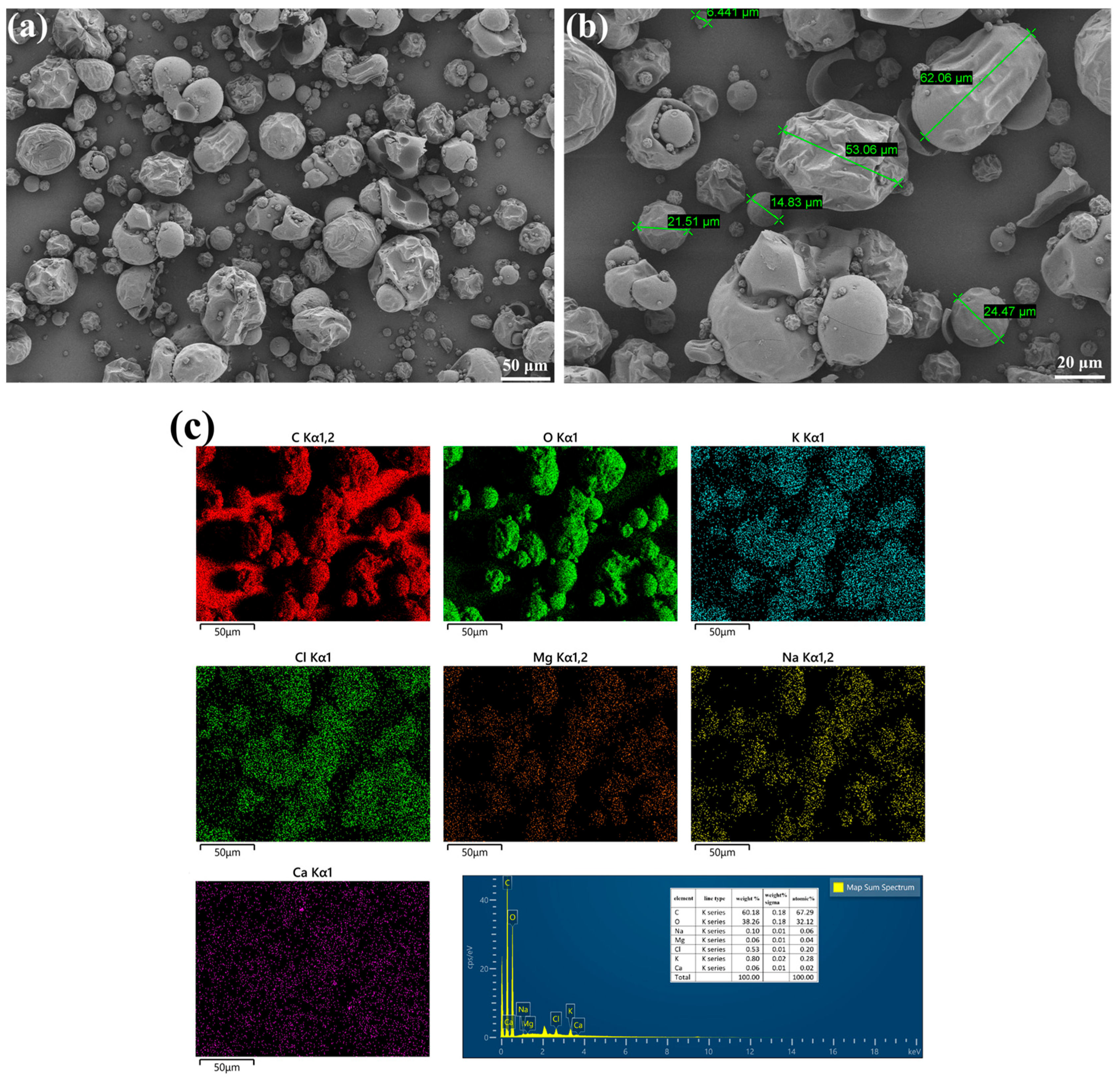
Figure 1. SEM images and EDS analysis of LLE: (a) morphology with low magnification; (b) morphology with high magnification; (c) EDS mapping result.
Coatings 15 00983 g001
Figure 2. FTIR pattern of LLE.
Coatings 15 00983 g002
Figure 3. Fluidity of cement paste incorporating different concentrations of LLE, wherein the blue curve represents the variation in cement paste with the amount of LLE, while the red curve shows the statistically fitted trend of flow variation with the amount of LLE.
Coatings 15 00983 g003
Figure 4. Flexural strength of mortar after incorporation of different concentrations of LLE, wherein the blue curve represents the variation in the flexural strength of mortar with the amount of LLE, while the red curve shows the statistically fitted trend of variation with the amount of LLE: (a) 7 days; (b) 28 days.
Coatings 15 00983 g004
Figure 5. Compressive strength of mortar after incorporation of different concentrations of LLE: (a) 7 days; (b) 28 days.
Coatings 15 00983 g005
Figure 6. FTIR patterns of mortars hydrated with different amounts of LLE after 28 days of hydration.
Coatings 15 00983 g006
Figure 7. Microscopic surface morphologies of mortar hydrated for 7 days with different dosages of LLE: (a,b) blank samples; (c,d) 0.2 wt% LLE; (e,f) 0.5 wt% LLE.
Coatings 15 00983 g007
Figure 8. Microscopic surface morphologies of mortar hydrated for 28 days with different dosages of LLE: (a,b) blank samples; (c,d) 0.2 wt% LLE; (e,f) 0.5 wt% LLE.
Coatings 15 00983 g008
Figure 9. SEM images of mortars mixed with different concentrations of LLE after 7 days of maintenance: (a) blank sample; (b) 0.2 wt% LLE; (c) 0.5 wt% LLE.
Coatings 15 00983 g009
Figure 10. SEM images of mortars mixed with different concentrations of LLE after 28 days of maintenance: (a) blank sample; (b) 0.2 wt% LLE; (c) 0.5 wt% LLE.
Coatings 15 00983 g010
Figure 11. Electrochemical impedance spectra of rebar in mortar with different concentrations of LLE: (a) Nyquist plot; (b) Bode impedance modulus plot; (c) Bode phase angle plot.
Coatings 15 00983 g011
Figure 12. Potentiodynamic polarization curves of the mortar–rebar samples with different concentrations of LLE.
Coatings 15 00983 g012
Figure 13. X-CT scans of (a) original mortar–rebar specimen, (b) 0.2 wt% LLE-modified mortar–rebar sample, and (c) 0.5 wt% LLE-modified mortar–rebar sample after immersion corrosion in 3.5 wt% NaCl solution.
Coatings 15 00983 g013
Figure 14. Schematic diagram of chloride-ion corrosion protection mechanism of (a) unmodified mortar and (b) LLE-modified mortar.
Coatings 15 00983 g014
Table 1. The main components of cement.
OxideCaOSiO2Al2O3Fe2O3MgOSO3Na2OK2OLOI
Content (wt%)62.6621.725.303.391.092.080.410.791.87
Table 2. Chemical composition of rebar [33].
RebarFeCSiMnSPCarbon Equivalent
HRB400Balance0.250.801.600.0450.0450.54
Table 3. EDS mapping results for the points in Figure 9.
PositionElements (at.%)
OCaSiAlS
A71.687.4817.762.120.96
B71.0915.738.313.551.31
C74.7714.924.243.252.82
D58.3626.3912.181.961.12
E72.9116.665.124.311.01
F61.1223.922.1312.540.29
Table 4. EDS point sweep results for the points in Figure 10.
PositionElements (at.%)
OCaSiAlS
A67.7220.935.873.042.45
B60.7633.694.190.760.60
C68.9518.059.292.171.54
D64.2322.1611.621.240.75
E65.214.9328.140.900.82
F72.6912.3112.251.601.14
Table 5. Electrochemical parameters of LLE-modified mortar–rebar samples.
LLE
(wt%)
Rs
(Ω·cm2)
Yf × 10−5
−1·sn·cm−2)
n1Rf
(kΩ·cm2)
Ydl × 10−5
−1·sn·cm−2)
n2Rct
(kΩ·cm2)
η
(%)
RSD
0 6.543.690.496.270.150.67116.11--
0.207.587.110.477.750.120.76157.8026.411.5
0.50 7.247.140.4310.140.080.77402.371.131.8
Table 6. Results of polarization curve analysis of pre-passivated rebars in mortars mixed with different concentrations of LLE.
LLE Contentβa
(mV/Dec)
βc
(mV/Dec)
Ecorr
(V)
icorr × 10−6
(A/cm2)
η
(%)
RSD
0 wt%5.893.87−0.942.69---
0.2 wt%6.093.13−0.800.5679.222.1
0.5 wt%7.541.68−0.630.5380.482.4
Table 7. Comparative analysis of corrosion protection properties between present study and others in literature.
Plant Extract SourceCorrosive MediumηReference
Urtica dioica leafAlkaline sodium chloride solution77.00%[24]
Damask Rose leafAlkaline sodium chloride solution81.90%[26]
Lotus leafAlkaline sodium chloride solution96.96%Our previous work [33]
Lotus leafMortar in sodium chloride solution80.48%This paper
Disclaimer/Publisher’s Note: The statements, opinions and data contained in all publications are solely those of the individual author(s) and contributor(s) and not of MDPI and/or the editor(s). MDPI and/or the editor(s) disclaim responsibility for any injury to people or property resulting from any ideas, methods, instructions or products referred to in the content.