Article

Taguchi Optimization of Corrosion Resistance and Wettability of a-C Films on SS316L Deposited via Magnetron Sputtering Technique

1
State Key Laboratory of Advanced Stainless Steel, Taiyuan University of Science and Technology, Taiyuan 030024, China
2
School of Mechanical Engineering, Taiyuan University of Science and Technology, Taiyuan 030024, China
3
School of Mechanical, Materials, Biomedical and Mechatronic Engineering, University of Wollongong, Wollongong 2522, Australia
4
College of Mechanical Engineering, Taiyuan University of Technology, Taiyuan 030024, China
5
Research and Development Department, Shanxi Taigang Stainless Steel Precision Strip Co., Ltd., Taiyuan 030006, China
*
Author to whom correspondence should be addressed.
Coatings 2025, 15(9), 1084; https://doi.org/10.3390/coatings15091084
Submission received: 21 August 2025 / Revised: 4 September 2025 / Accepted: 9 September 2025 / Published: 16 September 2025
(This article belongs to the Section Thin Films)

Abstract

Due to the exceptional corrosion resistance, chemical stability, and dense microstructure, carbon-based thin films are extensively employed in hydrogen energy systems. This study employed magnetron sputtering to fabricate amorphous carbon (a-C) films on SS316L substrates, aiming to improve the corrosion resistance of bipolar plates (BPs) in proton exchange membrane fuel cells (PEMFCs). Using a Taguchi design, the effects of working pressure, sputtering power, substrate bias, and deposition time on film properties were systematically examined and optimized. Films were examined via field emission scanning electron microscopy (FE-SEM), contact angle measurements, and electrochemical tests. Comprehensive evaluation by the Technique for Order Preference by Similarity to Ideal Solution (TOPSIS) method identified optimal conditions of 1.5 Pa pressure, 150 W radio frequency (RF) power, −250 V bias voltage, and 60 min deposition, yielding dense, uniform films with a corrosion current density of 1.61 × 10⁻⁶ A·cm−2 and a contact angle of 106.36°, indicative of lotus leaf-like hydrophobicity. This work enriches the theoretical understanding of a-C film process optimization, offering a practical approach for modifying fuel cell bipolar plates to support hydrogen energy applications.

1. Introduction

As one of the most versatile elements in nature, carbon exhibits a rich diversity of allotropes, including graphite, diamond, graphene, and carbon nanotubes. Each allotrope has distinct bonding configurations and physicochemical properties. These properties give carbon-based materials broad application potential in various technologies. Among carbon-based thin films, a-C lacks long-range atomic ordering. It has received growing attention as a surface functional coating. This is due to its chemical stability, corrosion resistance, adjustable electrical conductivity, and mechanical hardness [1,2,3]. Benefiting from these unique properties, a-C films have been widely applied in advanced technologies such as microelectronic devices, biomedical instruments, aerospace systems, and energy conversion applications [4,5,6].
In the PEMFC applications, BPs constitute approximately 80% of the total weight and 45% of the overall stack cost [7,8]. They perform critical functions such as distributing reactant gases and coolant, transmitting electrical current, providing mechanical support to the membrane electrode assembly, and removing water produced during reactions [9,10]. The operational performance and durability of BPs directly affect the overall efficiency and durability of the fuel cell stack. Given their excellent mechanical properties, metallic bipolar plates have attracted widespread attention. Among various metallic materials (such as copper or aluminum), SS316L is considered a promising material for BPs due to its high strength, formability, good electrical conductivity, and cost-effectiveness [11,12]. However, its susceptibility to corrosion under acidic and humid operating conditions severely limits its practical application potential [13,14]. To address this challenge, depositing a-C films on metallic surfaces has emerged as a research focus for enhancing both corrosion resistance and electrical performance [15,16,17]. Among various physical vapor deposition (PVD) techniques, magnetron sputtering has been widely employed for the fabrication of high-performance a-C films due to its advantages of low deposition temperature, strong interfacial adhesion, dense and uniform film structure, and precisely controllable process parameters [18,19].
Although magnetron sputtering is commonly used to prepare a-C coatings, the properties of the deposited films are strongly influenced by the deposition parameters. According to Li [20], the corrosion protection of metallic BPs is mainly provided by the carbon film at lower corrosion potentials, while at higher potentials, the substrate’s corrosion resistance becomes more critical. Using close-field unbalanced magnetron sputtering ion plating (CFUBMSIP), Yi and Jin [21,22] deposited carbon films on stainless steel, which significantly enhanced the power density of the stack and reduced the interfacial contact resistance (ICR) of the BPs. However, noticeable performance variations were observed under different deposition conditions. Furthermore, Larijani [23], Li [24], and Ahamd [25] investigated the effects of corrosion rate, pulse frequency, and bias voltage, confirming that substrate bias, gas flow rate, sputtering power, and deposition temperature exert significant influences on film structure and sp2/sp3 bonding ratio. Bi [26,27] systematically explored the effects of substrate bias and argon flow rate on film structure, ICR, and corrosion performance, while Do [28] validated the trend of sp3 content evolution through molecular dynamics simulations. Additionally, Alaefour [29] and Feng [30] demonstrated the pronounced impact of sputtering power and working gas flow rate on film density and electrical conductivity. Yari [31], Afshar [32], and Dong [33] further revealed the coupled influences of deposition temperature and film thickness on film compactness, pore defect formation, and ICR performance, noting that deposition temperatures exceeding 400 °C tend to induce structural defects, thereby compromising the protective integrity of the films.
Most previous investigations of a-C films deposited by magnetron sputtering have primarily addressed the impact of individual process variables, while systematic studies on the synergistic effects of multi-parameter coupling remain scarce. This limitation has led to major inconsistencies in reported findings. It has hindered the controllable fabrication of high-performance a-C films. This restricts their industrial use, especially in critical applications like PEMFC metallic bipolar plates [34,35]. To address this multi-objective optimization challenge, the present study employs an integrated approach combining the Taguchi orthogonal experimental design with the TOPSIS. The Taguchi method, as a highly efficient and statistically robust experimental design strategy, significantly reduces the experimental workload through signal-to-noise (S/N) ratio analysis and preliminarily identifies the optimization direction for individual performance indicators [36,37,38]. However, the Taguchi approach alone is inadequate for resolving trade-offs among multiple conflicting responses. Therefore, TOPSIS is further introduced to aggregate multiple S/N ratio results into a comprehensive composite score, thereby identifying the globally optimal parameter set from the Taguchi experimental trials. This step ensures a thorough and objective evaluation, facilitating rational and reliable decision-making in the presence of competing performance metrics [39]. Oscar applied this method to the selection of thermoplastic polymer bipolar plate materials [40], while Cai employed it to evaluate the influence of flow field designs on bipolar plate performance, offering new insights for developing novel flow fields with enhanced comprehensive properties [41]. Nevertheless, its application in the optimization of magnetron-sputtered a-C films is still limited, and systematic explorations under realistic fuel cell operating conditions are largely absent.
In this study, unbalanced magnetron sputtering was utilized to achieve coupled optimization of four key process parameters, namely working pressure, sputtering power, bias voltage, and deposition time, on SS316L substrates for bipolar plates. By integrating the Taguchi method, the inherent constraints of single-factor analyses were effectively addressed, and the properties of a-C films under the harsh operational environments of fuel cells were systematically investigated. To satisfy the dual requirements of corrosion resistance and wettability that are essential for bipolar plate performance, the films were comprehensively characterized using FE-SEM, water contact angle measurement, and potentiodynamic polarization testing. Furthermore, the TOPSIS was applied to quantitatively evaluate the overall film performance under multi-parameter conditions. The outcomes are expected to offer valuable insights for optimizing a-C film deposition processes and promoting their reliable application in PEMFC metallic bipolar plates.

2. Experimental

2.1. Materials and Preparation

The substrate employed in this experiment was made of SS316L and p-type Si (100) wafers (Electronic Technology Co., Ltd., Zhejiang, China). The SS316L stainless steel, with a thickness of 0.1 mm, was provided by Shanxi Taigang Stainless Steel Precision Strip Co., Ltd. (Taiyuan, China). Its chemical composition is displayed in Table 1. Both substrate types were cut into 20 mm×20 mm samples before deposition. These specimens were first ultrasonically cleaned in anhydrous ethanol (China National Medicines Group Ltd. Reagent Co., Shanghai, China) for 15 min, followed by sequential rinsing with ethanol and distilled water (China National Medicines Group Ltd. Reagent Co.,Shanghai, China), and finally air-dried at room temperature. This cleaning process aimed to eliminate surface contaminants and improve chemical activity, thus facilitating better adhesion during the subsequent deposition of the a-C films.
In this study, an unbalanced magnetron sputtering system (JST-600BY, Beiyu Vacuum Technology Co., Ltd., Shenyang, China) was used to deposit films on bipolar plates for hydrogen fuel cells, as illustrated in Figure 1. Prior to film deposition, specific pre-treatment procedures were conducted on both the sputtering chamber and the SS316L substrates to ensure optimal film conditions. Initially, the argon flow rate and gate valve angle were set to achieve a chamber vacuum pressure of approximately 8×10⁻³ Pa. Under this high-vacuum condition, argon was injected at a flow rate of 100 SCCM, and a bias voltage of −850 V was applied for 15 min to perform a plasma cleaning process. This procedure effectively removed surface contaminants, oxides, and other residual impurities from both the chamber and the stainless steel substrates.
Subsequently, the argon flow rate was reduced to 30 SCCM, and the chamber pressure was stabilized at 0.5 Pa. An Ar+ source operated at 350 V was employed to ionize the argon, generating Ar+ ions that continuously bombarded the surface of the SS316L substrate for 15 min. This ion bombardment process not only increased the surface roughness of the substrate but also enhanced its surface activity, thereby improving the adhesion strength and uniformity of the subsequently deposited films.

2.2. Taguchi Design of Experiments

The Taguchi design approach is a statistical optimization technique utilizing orthogonal array (OA) experimental design, which enables the identification of the most significant process parameters and their optimal combinations through a relatively small number of experimental trials. This methodology effectively reduces experimental cost and variability, and has been widely applied in the quantitative evaluation of process performance. Subsequently, the TOPSIS method was employed to optimize the multiple response metrics obtained from the Taguchi experiments. By assigning different weights to the process parameters according to their influence on the overall film properties, the relative closeness of each alternative to the ideal solution was calculated, thereby determining the optimal process parameter combination. In the present study, the Taguchi approach was adopted to examine the effects of magnetron sputtering parameters on the properties of a-C thin films. The deposition behavior of the films was predominantly influenced by four key process parameters, namely sputtering power, working pressure, bias voltage, and deposition time. Detailed specifications of these parameters are provided in the Supplementary Materials [10,28,42,43,44,45,46,47,48,49,50,51,52,53,54,55].
To evaluate both the film formation quality and the functional performance of coated BPs in simulated fuel cell environments, these four parameters were selected as the experimental factors: working pressure (factor A), sputtering power (factor B), bias voltage (factor C), and deposition time (factor D). Each parameter was assigned three levels, and an L9 [34] orthogonal array was constructed, requiring only nine experimental runs, as displayed in Table 2. The levels assigned to each factor were informed by an extensive review of prior studies on magnetron-sputtered a-C films deposited on stainless steel substrates [10,18,26,56,57], ensuring both the rationality and feasibility of the parameter ranges.
Specifically, the working pressure was set at 0.4, 1.0, and 1.5 Pa; the sputtering power at 150, 200, and 250 W; the bias voltage at −120, −200, and −250 V; and the deposition time at 30, 60, and 90 min, as summarized in Table 2 and Table 3. The film thickness, corrosion potential (Ecorr), corrosion current density (Icorr), and contact angle were selected as evaluation indicators. These response variables were used to determine the main effects and interaction effects of each process parameter, thereby enabling a comprehensive assessment of the influence of different factors and their levels on the properties of the a-C thin films.
An RF sputtering source with a high-purity graphite target (99.99%, Hengyang Aona New Material Co., Ltd., Hengyang, China) was utilized for film deposition. Throughout the process, the chamber pressure was kept at approximately 0.5 Pa by controlling the throttle valve, with high-purity argon (99.99%) serving as the sputtering gas. In accordance with the Taguchi experimental design, the equipment parameters were systematically adjusted to deposit the corresponding a-C thin films onto the surface of SS316L substrates.

2.3. Film Evaluation

To directly examine the film morphology, field emission scanning electron microscopy (FE-SEM, Hitachi S-4800, Hitachi High-Tech Corporation, Tokyo, Japan) was used to observe the cross-sectional morphology of the a-C films prepared on a silicon wafer [27,35]. Additionally, energy-dispersive X-ray spectroscopy (EDS) attached to the FE-SEM was employed to analyze the elemental distribution of the a-C films. Both SEM imaging and EDS analysis were carried out under the same primary conditions: an accelerating voltage (EHT) of 15.00 kV and a working distance (WD) of 8.2 mm. All these characterization procedures were carried out prior to the electrochemical corrosion tests. X-ray photoelectron spectroscopy (XPS) measurements were conducted using a Thermo Scientific K-Alpha instrument (Thermo Fisher Scientific Inc., Waltham, MA, USA) with a monochromatic Al Kα X-ray source (hv = 1486.6 eV). The analysis energy is set to 20 eV, and the spot size of the measurement area is 200 μm × 400 μm, in order to determine the elemental composition and chemical states on the sample surface.
The contact angles of both uncoated SS316L substrates and a-C films were measured using a video contact angle meter (JY-82C, Chengde Dingsheng Testing Machine Manufacturing Co., Ltd., Chengde, China). A 3 μL droplet of deionized water was carefully dispensed vertically onto the sample surface using a microsyringe. The interaction between the droplet and the substrate was recorded by a digital imaging system (Chengde Dingsheng Testing Machine Manufacturing Co., Ltd., Chengde, China), and the contact angle was determined through image analysis software (ImageJ 1.54g). Measurements were taken at three different locations on each sample, and the average value was calculated to ensure accuracy and repeatability. In addition, the surface morphology and roughness of the samples were characterized to assess the hydrophobic characteristics of the BPs.
The corrosion resistance of the SS316L substrates and coated samples was evaluated using an electrochemical workstation (CHI660E, CH Instruments, Inc., Shanghai, China). Electrochemical measurements (CH Instruments, Inc., Shanghai, China) were performed with a three-electrode configuration, comprising a working electrode (SS316L BPs coated with different a-C films, with an exposed area of 1 cm2), a reference electrode (saturated Ag/AgCl electrode, 0.199 V vs. SHE (Standard Hydrogen Electrode), and a counter electrode (platinum mesh, 20 × 20 mm2). The electrolyte consisted of a 0.5 mol/L H2SO4 (China National Medicines Group Ltd. Reagent Co., Shanghai, China)solution containing 0.1 ppm HF (China National Medicines Group Ltd. Reagent Co., Shanghai, China), and the test temperature was maintained at 80 °C tosimulate the cathodic environment of PEMFCs. Potentiodynamic polarization tests were performed at a scan rate of 0.01 V/s, while electrochemical impedance spectroscopy (EIS) measurements (CH Instruments, Inc., Shanghai, China) were conducted over a frequency range from 105 Hz to 10−2 Hz. To ensure reproducibility, all tests were repeated three times independently.

3. Thin Film Growth Morphology Analysis

In the orthogonal experiments, a-C films on SS316L BPs prepared under different process parameter combinations exhibited variations in cross-sectional morphology and carbon chemical states. These differences significantly influenced the corrosion resistance of the films in PEMFC environments, which closely correlated with the compactness and uniformity of the protective surface layer. For a more detailed investigation of the film cross-section and surface chemical states, FE-SEM coupled with EDS was employed to characterize samples C1–C9, with the results shown in Figure 2.

3.1. Microstructural Characterization

The growth mechanism of carbon-based films on SS316L substrates during magnetron sputtering is primarily governed by the synergistic effects of ion bombardment energy and target material properties. In an argon atmosphere, plasma is excited by a RF power supply, where high-energy electrons collide with argon atoms to generate argon ions (Ar+) and free electrons. Under the influence of the electric field, Ar+ ions are accelerated toward the graphite target, resulting in bombardment that ejects carbon atoms or clusters. These species then diffuse to the SS316L substrate surface, where they undergo nucleation and film growth. The kinetic energy transferred during Ar+ impact allows some carbon atoms to attain energies exceeding the surface binding threshold, leading to their ejection as sputtered particles. Upon traversing the plasma region, these particles reach the substrate and contribute to the nucleation and growth of the carbon film.
Deposition parameters, particularly the working pressure, critically influence atomic transport and surface kinetics, thereby determining the resulting microstructure. FE-SEM observations indicate that, under deposition pressures ≤ 1.0 Pa, the a-C films exhibit dense, continuous, and uniform morphologies with well-defined film–substrate interfaces. In contrast, films prepared under C5, C6, C7, and C9 parameter sets (corresponding to pressures ≥ 1.0 Pa) display varying degrees of columnar stacking. This behavior is attributed to the extended mean free path and enhanced surface mobility of carbon atoms under high-vacuum conditions, which facilitate ordered arrangement on the substrate, promoting compact and homogeneous structures. At higher pressures, reduced atomic kinetic energy and limited mobility restrict surface diffusion, resulting in disordered stacking and heterogeneous morphologies.
The measured thicknesses of C1, C2, and C3 films are approximately 44 nm, 55 nm, and 50 nm, respectively. The film in C2 exhibits a notably increased thickness, a smoother surface, and more pronounced columnar structures, whereas C3 shows pronounced surface protrusions, wider columns, and relatively rough morphology. These observations suggest that, at lower RF power, the reduced deposition rate allows sufficient time for carbon atoms to migrate and preferentially grow along specific orientations, forming columnar structures. Increasing the RF power to 200 W enhances atomic activity, promoting rapid formation of compact and well-developed columnar structures on the SS316L surface.
At pressures ≥ 1.0 Pa, the increased collision frequency among argon molecules enhances scattering of migrating carbon atoms, leading to the emergence of three distinct surface morphologies. SEM images of C4, C5, and C8 demonstrate that continuous carbon atom arrangement favors relatively smooth film surfaces, whereas other samples exhibit pronounced surface undulations, irregular textures, and particle agglomeration. Notably, C7 shows the greatest film thickness, characterized by a mixed layered and granular morphology, attributed to the combined effect of 150 W RF power and a 60 min deposition time. Moreover, C9 exhibits the highest density of pores and irregular surface features due to prolonged deposition. These findings confirm that frequent collisions reduce the kinetic energy of carbon atoms, limiting surface diffusion and adversely affecting film density and morphology.
Cross-sectional FE-SEM images of C5, C9 (Figure 2e,i) reveal typical island-like discontinuous defects for a deposition time of 30 min. Such defects compromise film–substrate adhesion, primarily due to insufficient nucleation. Although the two samples were deposited for identical durations, variations in deposition bias voltage and RF power resulted in differences in particle energy.

3.2. Mechanistic Insights into Film Formation

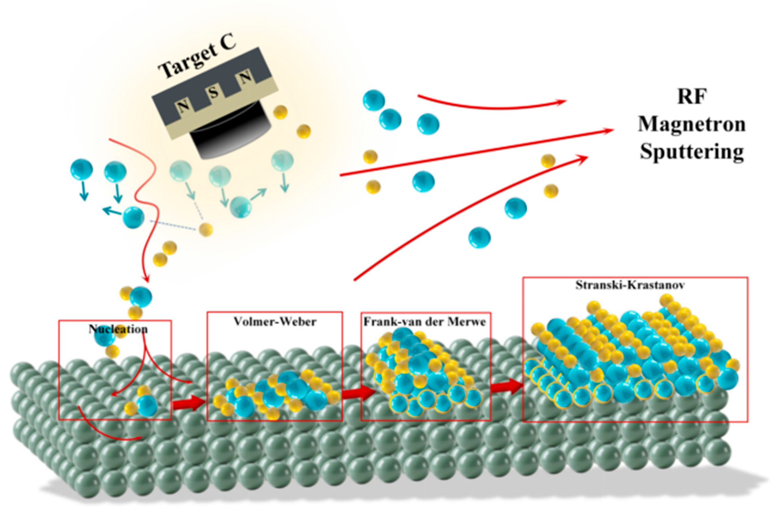
Based on FE-SEM morphological analysis, three key phenomena occurring during magnetron sputtering can be sequentially described in three stages, corresponding to the fundamental mechanisms of thin film growth (Figure 3):

3.2.1. Initial Stage: Atomic Deposition, Diffusion, and Ducleation

Under bombardment by high-energy argon ions, graphite atoms are ejected from the target and travel toward the SS316L substrate with specific kinetic energies and directional distributions. Upon arrival, carbon atoms interact weakly with substrate atoms via van der Waals forces or electron cloud overlap. Surface features such as grain boundaries, defects, and native oxide layers act as preferential nucleation sites. Incoming carbon atoms diffuse across the substrate seeking energetically favorable deposition sites, leading to random aggregation of atomic clusters and formation of nanoscale agglomerates, commonly referred to as isolated island-like structures. Growth follows the Volmer-Weber mode, as observed in C6, serving as initial “seeds” for subsequent thin film growth.

3.2.2. Film Formation: Island Growth and Coalescence

With continued deposition, increasing numbers of carbon atoms arrive and aggregate around existing clusters. The isolated islands grow laterally and vertically through continuous adsorption and surface diffusion. As clusters enlarge, inter-island spacing decreases, leading to coalescence and formation of more continuous and uniform films. Growth is governed by the competition between surface diffusion kinetics and nucleation rate. High surface mobility promotes lateral growth and coalescence, whereas local deposition fluctuations or surface energy heterogeneity may induce voids, ridge-like features, or columnar structures. This aggregation-driven stage critically determines film microstructure, surface morphology, and interfacial adhesion. Coalescence is accompanied by atomic rearrangement and structural optimization, eventually forming dense polycrystalline or columnar structures. Island edges and corners, with high surface energy and low atomic coordination, serve as active sites for diffusion and coalescence [58].

3.2.3. Film Growth: Competition of Layer-by-Layer Growth

Continuing deposition leads to the formation of amorphous or nanocrystalline structures. Ideally, each atomic layer self-organizes to uniformly cover the preceding layer, producing atomically smooth surfaces and minimizing system surface energy. This process, referred to as the Frank-van der Merwe (FM) mechanism, represents the optimal pathway for smooth, continuous films [59]. Variations in working pressure, RF power, and bias voltage influence the kinetic energy and trajectory of incident atoms, affecting competition between layer-by-layer and island growth modes, typically yielding mixed microstructures (e.g., C2 and C7, Figure 2b,g). Substrate defect regions or areas of enhanced atomic mobility favor continuous layers, whereas low-mobility regions retain isolated islands. Protruding islands may induce lattice mismatch strain, forming dislocations or microcracks; incomplete coverage in layer-grown regions may produce nanoscale voids or pinholes, reducing density and structural integrity. These interactions highlight the necessity for precise optimization of sputtering parameters. The proposed model refines the classical Volmer-Weber mode by enhancing nucleation via surface activation, suppressing island coalescence, and promoting lateral growth, resulting in smoother, denser films.

3.3. XPS Analysis

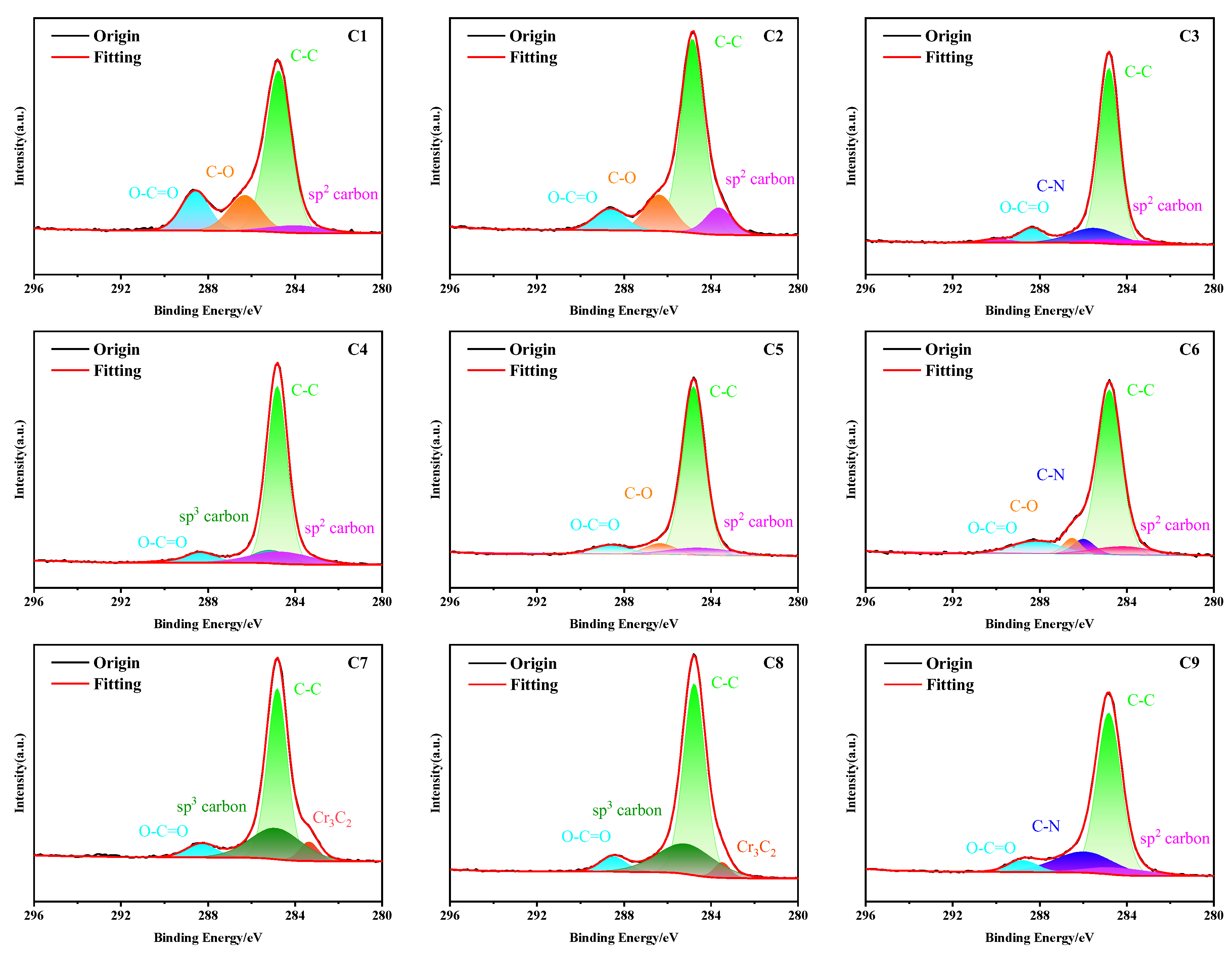
The XPS survey spectra and high-resolution C 1s spectral fitting results revealed significant differences in the surface oxygen-containing functional group content and graphitization degree among different samples. As displayed in Figure 4, each sample displays a pronounced peak near 284.8 eV, associated with C−C/C=C (sp2/sp3) hybridized bonds, indicating that the a-C films predominantly consist of a carbon-carbon bonded framework. As a hallmark of the conjugated π bond structure, the sp2 carbon component has the highest intensity in sample C1, with a peak area fraction of approximately 45%. This trend indicates that the bias parameter regulates the nucleation of carbon clusters and the balance between sp2/sp3 hybridization. In addition, a peak observed at 285.5 eV is attributed to C−O bonds, with notably higher intensity in the C1, C2, and C7 samples, suggesting the presence of abundant oxygen-containing functional groups or adsorbed oxygen on the film surface. When correlated with the cross-sectional FE-SEM images in Figure 2, it was evident that the relative peak areas of oxygen-containing functional groups varied with the deposition parameters in the orthogonal experimental design, indicating that the surface oxygen functional group content could be effectively regulated through process optimization. This trend is consistent with the changes in film compactness observed in the SEM-EDS surface mapping results: as the film structure becomes denser, the amount of surface oxygen-containing functional groups tends to decrease, and vice versa.
It is noteworthy that, despite the relatively low degrees of graphitization in the C7 and C8 phases, their surfaces are enriched with polar functional groups such as C=O and C−O−C, which form strong covalent interactions with Cr in Cr-rich stainless steel. This interaction significantly enhances the interfacial hydrophilicity of the composite. These polar groups can effectively hinder the penetration and diffusion of corrosive media in service environments, thereby enhancing the corrosion resistance of the films. Consequently, these samples are anticipated to exhibit excellent corrosion resistance under simulated operating conditions for stainless steel bipolar plates.

4. Results and Discussion

4.1. Surface Wettability of a-C Films

During the operation of PEMFCs, water is produced as a byproduct of the oxygen reduction reaction and gradually accumulates within the flow channels of the BPs. If water readily adheres to the surface of BPs, it can lead to uneven gas distribution, prolonged blockage of the flow channels, and even accelerate corrosion by maintaining continuous contact between corrosive ions and the metal surface. Therefore, the a-C film’s superior compactness and hydrophobicity serve as the first physical barrier against the permeation of corrosive media under operational conditions, following surface modification of stainless steel BPs.
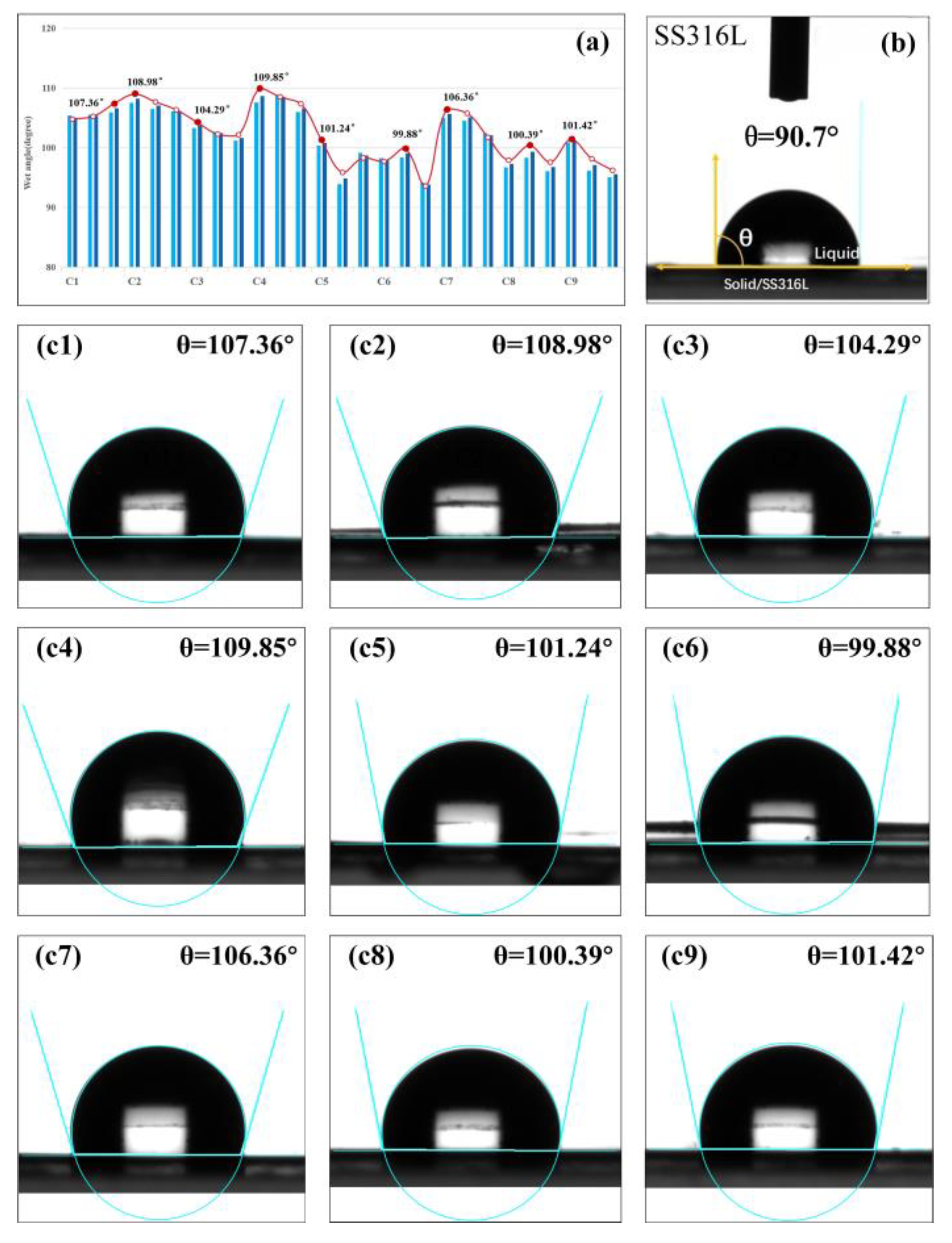
To evaluate the wettability of the BP surfaces, a liquid meniscus shape analysis method was employed to measure the contact angle (θ), as illustrated in Figure 5. Compared to the bare SS316L BPs, all nine carbon-based films prepared through orthogonal experimental design exhibited significantly increased contact angles, each exceeding 90.70°. Among them, the C4 sample demonstrated the highest average contact angle of 109.85°, while the C6 sample showed a relatively lower value of 99.88°. The water droplets exhibited a nearly spherical morphology on these coated surfaces, indicating a pronounced resistance to wetting and excellent hydrophobic behavior. This enhanced hydrophobicity not only endows the coated BPs with lower permeability and improved anti-wettability during operation, but also effectively suppresses water accumulation on the plate surfaces, thereby mitigating the risk of flow channel blockage caused by liquid water.

4.2. Electrochemical Corrosion Behavior

To assess the corrosion resistance of the coated SS316L BPs under simulated PEMFC operating conditions, the prepared samples were exposed to an acidic environment containing 0.5 M H2SO4 and 0.1 ppm HF at 80 °C. This experimental condition effectively simulated the aggressive corrosive environment typical of actual PEMFC operation.
Electrochemical polarization testing is a widely adopted method for evaluating the electrochemical behavior of coated BPs in fuel cell environments. Figure 6 presents the resulting polarization curves for both the coated samples (C1–C9) and uncoated SS316L BPs, measured in the acidic electrolyte. As summarized in Table 4, the results indicate significant differences in corrosion resistance among the a-C films fabricated under various process parameters. However, the overall polarization behavior exhibited similar trends across all coated samples. In the anodic region, passive regions of varying extents were observed for the coated plates. Notably, C8 and C9 samples exhibited no apparent breakdown potential within the potential range of 0.2–1.0 V, while the current density remained consistently around 10−6 A/cm2, indicating the formation of dense passive films.
Compared to bare SS316L substrate, the Ecorr of C1, C2, C5, C7, and C9 displayed a positive shift, with the C7 sample achieving the highest value of 0.5 V. Furthermore, the Icorr of the coated samples, except for C4 and C5, was markedly reduced relative to the uncoated SS316L, indicating an effective protective effect provided by the a-C films. Significantly, the C1 and C7 films exhibited the lowest corrosion current densities, with C7 achieving the most favorable performance, recording a minimum corrosion current density of only 1.61×10⁻⁶ A/cm2. This result is consistent with the findings from the XPS survey and high-resolution C 1s spectra shown in Figure 3, which reveal that the C7 sample possesses relatively larger peak areas associated with oxygen-containing functional groups (C−O, C=O, and O−C=O) and lower degrees of graphitization. The enrichment of these polar oxygen functional groups contributes significantly to improved corrosion resistance, further supporting the electrochemical findings.
Conversely, the corrosion current densities of C4 and C5 exceeded that of the uncoated substrate, suggesting inferior corrosion resistance. FE-SEM analyses revealed that the films on these two samples were uneven and exhibited an island-like morphology, which likely accelerated localized corrosion in the acidic environment (see Figure 2d,e). Additionally, corrosion rates for each sample were calculated based on Faraday’s law, revealing a consistent trend with the corrosion current density results. Notably, C7 achieved the lowest corrosion rate of 0.018 mm/y, confirming that this parameter combination offers the most enhanced corrosion resistance.

4.3. Electrochemical Impedance Spectroscopy

EIS serves as an essential method for assessing the corrosion resistance of stainless steel bipolar plates after film. As illustrated in Figure 7, Nyquist and Bode plots are presented for both the bare 316L bipolar plate and the nine a-C-coated samples prepared under different parameter sets within the orthogonal array, all tested in a simulated PEMFC environment.
In Nyquist plots, the capacitive diameter represents the charge transfer resistance of the sample, indicating that a larger diameter corresponds to better corrosion resistance. As depicted in Figure 7a, the diameters of C3, C4, and C5 samples were comparable to that of the bare SS316L BPs, whereas C1 and C7 samples exhibited noticeably larger diameters, reflecting superior corrosion resistance. Moreover, the diameter of C7 was more complete and well-defined, suggesting a denser and more uniform film structure.
The Bode impedance plots in Figure 7c directly revealed the absolute impedance (|Z|) response. In the low-frequency region, a higher |Z| value indicates enhanced corrosion protection, while the |Z| value in the high-frequency region reflects the compactness of the film. C7 displayed the highest |Z| value at low frequencies and a slightly lower |Z| than C1 in the high-frequency region. Overall, these results demonstrate that C7 possesses superior corrosion resistance and film compactness.
Additionally, the Bode phase angle plots are detailed in Figure 7d. Compared with the bare SS316L substrate, C4 and C5 exhibited a rapid decline in phase angle in the mid-to-high-frequency region. This suggests the presence of defects in these films, which accelerates the corrosion process. In contrast, the remaining a-C-coated samples maintained relatively stable phase angles. Notably, C1, C2, C6, and C7 presented broad and high phase angle plateaus, with C7 exhibiting the highest value, approaching 90°. This indicates the most effective barrier property and corrosion protection among the tested samples.
Subsequently, the EIS spectra were analyzed using the equivalent circuit model provided in Figure 7b to further evaluate the corrosion resistance of the coatings, with the corresponding fitting results detailed in Table 5. The equivalent circuit includes Rs (solution resistance), Rf (film resistance), Rct (charge transfer resistance), as well as CPEf and CPEdl, representing the capacitance of the protective film and the electric double-layer, respectively. A comparison of the fitted parameters for the nine coated samples revealed that both C1 and C7 exhibited higher Rf and Rct values than the others. In particular, C1 demonstrated the highest Rct, approximately 7.64 × 10³ Ω·cm2, indicating significantly enhanced corrosion protection. This outcome aligns well with the electrochemical corrosion test results, confirming the robustness of the coating’s barrier performance.

4.4. S/N Analysis

In the Taguchi approach, the S/N ratio is commonly employed as a criterion for evaluating the stability of the experimental system and the quality of performance characteristics. The S/N ratio can be categorized into three types depending on the desired performance: nominal-the-best, smaller-the-better, and larger-the-better [60]. In this study, both corrosion potential and contact angle were considered larger-the-better characteristics, while corrosion current density was regarded as a smaller-the-better characteristic. Accordingly, the S/N ratios were calculated using Equations (1) and (2), respectively.
The experimental results for the corrosion potential, corrosion current density, and contact angle of the a-C films prepared under various process parameter combinations, along with their corresponding S/N ratios, are summarized in Table 6.
S / N = 10 × log 10 1 n i = 1 n 1 y i 2
S / N = 10 × log 10 1 n i = 1 n y i 2
where n is the number of experimental repetitions; and yi refers to the response value, representing the performance outcome measured in the i-th experiment.
Among the nine experimental runs, the deposition parameter set A3B1C3D2 (C7) yielded the highest corrosion potential. Meanwhile, the a-C films prepared under the parameter combination A3B1C3D2 (C7) exhibited the lowest corrosion current density. Additionally, the film fabricated with parameters A2B1C2D3 (C4) demonstrated the largest contact angle.
Analysis of variance (ANOVA) was performed on the experimental data to identify the deposition process parameters that significantly influence the performance characteristics of a-C films coated on stainless steel substrates [61]. The variance and percentage contribution of each process parameter examined in this study can be determined using Equations (3) and (4).
S m = η i 2 9 ,   S X = η X i 2 N S m
V X = S X f x ,   P X = V X V T × 100 %
where Sm denotes the sum of squares due to the means; and SX represents the sum of squares attributed to process parameter X (working pressure, sputtering power, bias voltage, and deposition time). ηi indicates the S/N ratio for each experiment (i = 1–9). ηXi refers to the sum of the i level of process parameter X (i = 1–3). N stands for the repeating number of each level of parameter X. VX is the variance of parameter X, fX denotes the degrees of freedom of parameter X which equals the level number of parameter X−1, VT corresponds to the total variance, and PX indicates the percentage contribution of parameter X.
Table 7 summarizes the ANOVA results for corrosion potential, corrosion current density, and contact angle of a-C films deposited via magnetron sputtering, detailing the contribution of each process parameter. It was found that deposition time predominantly influences the corrosion potential, accounting for 45.35% of the total variance, while working pressure and power contribute 24.49% and 21.41%, respectively. This indicates that longer deposition time and lower bias voltage correspond to a lower corrosion potential of the deposited films. Conversely, working pressure exerts the greatest influence on corrosion current density, with a contribution of 66.83%, far exceeding those of the other parameters, while sputtering power contributes only 1.41%. Specifically, higher sputtering pressure, lower power, and lower bias voltage result in reduced corrosion current density. Regarding the contact angle, sputtering power has the most significant effect, contributing 48.36%. Further insights were obtained by analyzing the S/N response plots of the three parameters.
The greater the deviation of the plot from the baseline, the higher the rank, indicating a more significant process parameter. As illustrated in Figure 8, analysis of the S/N response for the prepared samples revealed the optimal process parameters for achieving the highest corrosion potential on the SS316L substrate surface coated with a-C films as follows: A3B2C3D1, corresponding to a working pressure (factor A) of 1.5 Pa, sputtering power (factor B) of 200 W, bias voltage (factor C) of −250 V, and deposition time (factor D) of 30 min.
The optimal parameter set for achieving the lowest corrosion current density was determined as A2B3C2D3, corresponding to a working pressure of 1.0 Pa, sputtering power of 250 W, bias voltage of −200 V, and deposition time of 90 min. Regarding the best contact angle, the most favorable parameters were A1B1C2D2, corresponding to a working pressure of 0.4 Pa, sputtering power of 150 W, bias voltage of −200 V, and deposition time of 60 min. Subsequent detailed analysis was conducted using the S/N response plots of these three parameters.

4.5. Comprehensive Performance Analysis

The experimental results clearly demonstrate that the magnetron sputtering process parameters significantly influence the properties of carbon-based films deposited on SS316L substrates. In the orthogonal experiments, four process parameters and three performance metrics were considered. The results revealed conflicting trends among the performance indicators, making it challenging to identify a unified optimal condition. Therefore, the TOPSIS method was employed in this study to comprehensively analyze the experimental results of each evaluation index. Different weights were assigned based on the influence of each parameter on the overall performance of the a-C films. By calculating the relative closeness of each sample to the ideal solution, the comprehensive performance of the films was quantitatively assessed, and the optimal process parameters were identified. This method offers the advantage of effectively balancing the significance of conflicting performance criteria, enabling a rational and objective evaluation of the overall performance [62,63].
During the operation of fuel cells, corrosion-induced degradation of BPs is one of the primary failure mechanisms. In other words, the corrosion resistance of coated BPs is critical to their service life. Therefore, in the comprehensive performance evaluation, the corrosion potential and corrosion current density of the coated BPs were assigned the highest weighting factors of 40% each. In contrast, the contact angle, which primarily reflects the compactness and hydrophobicity of the deposited films without directly affecting the operational performance of the BPs, was assigned a weighting factor of 20% [43].
The experimental results for each performance metric were first normalized, followed by a weighted calculation to obtain the comprehensive performance scores, as summarized in Table 8. The ranking of the overall performance from the orthogonal experiments was determined as follows: C7 > C1 > C2 > C9 > C5 > C8 > C3 > C6 > C4. It is evident that the C7 parameter combination exhibited the highest comprehensive performance score of 0.995, while C4 showed the lowest value of only 0.048.

5. Conclusions

The a-C films were deposited by RF magnetron sputtering under different deposition parameters according to the Taguchi design method. The experimental results lead to the following conclusions:
  • Based on cross-sectional morphology observations by FE-SEM combined with atomic migration and collision theory, the physical growth mechanism of a-C films was systematically investigated. The study revealed the competitive mechanism between island-like and layer-by-layer growth modes, confirming that sputtered carbon atoms undergo a complex dynamic process involving surface diffusion, cluster aggregation, and structural evolution on the substrate surface. These findings provide a theoretical foundation for the structural regulation of thin films.
  • The orthogonal experimental results demonstrated that deposition time predominantly influenced corrosion potential (45.53%), working pressure significantly affected corrosion current density (66.83%), and sputtering power was the primary factor governing contact angle (48.36%), providing quantitative insight into the coupled effects of process parameters on a-C films’ performance.
  • A comprehensive performance evaluation of the a-C films was conducted using the TOPSIS method. The optimal set of process parameters was identified at a working pressure of 1.5 Pa, sputtering power of 150 W, substrate bias of −250 V, and a deposition time of 60 min. Under these conditions, the corrosion current density reached a minimum of 1.61 × 10⁻⁶ A·cm−2, and the corresponding corrosion rate was reduced to 0.018 mm/y. This study provides a reliable process optimization strategy and performance enhancement solution for the surface modification of fuel cell bipolar plates.

Supplementary Materials

The following supporting information can be downloaded at: https://www.mdpi.com/article/10.3390/coatings15091084/s1.

Author Contributions

Conceptualization, X.Y., J.Z., H.D. and T.W.; methodology, X.Y., C.Z., J.Z. and H.D.; validation, X.Y., C.Z., Z.J. and T.W.; resources, H.D. and T.W.; formal analysis, X.Y. and C.Z.; data curation, X.Y., J.Z. and T.W.; writing—original draft preparation, X.Y.; writing—review and editing, C.Z. and Z.J.; visualization, X.Y. and C.Z.; supervision, C. Z. and Z.J.; funding acquisition, C.Z. and T.W. All authors have read and agreed to the published version of the manuscript.

Funding

This research was funded by the National Natural Science Foundation of China, grant number 52375361.

Institutional Review Board Statement

Not applicable.

Informed Consent Statement

Not applicable.

Data Availability Statement

Data are contained within the article.

Conflicts of Interest

Author Tianxiang Wang was employed by the company Shanxi Taigang Stainless Steel Precision Strip Co., Ltd. Author Haojie Duan was employed by the company Shanxi Taigang Stainless Steel Precision Strip Co., Ltd. The remaining authors declare that the research was conducted in the absence of any commercial or financial relationships that could be construed as a potential conflict of interest.

References

  1. Aono, M.; Terauchi, M.; Sato, Y.K.; Morita, K.; Inoue, T.; Kanda, K.; Yonezawa, K. Deposition of Amorphous Carbon Nitride Thin Films Using Pressure-Gradient RF Magnetron Sputtering and Their Chemical Bonding Structures. Appl. Surf. Sci. 2023, 635, 157677. [Google Scholar] [CrossRef]
  2. Yang, X.; Zhou, C.; Wang, T.; Zhao, J. Construction and Electrochemical Corrosion Behavior of Carbon-Based Thin Films on SS316L Bipolar Plates by Magnetron Sputtering. Appl. Surf. Sci. 2025, 698, 163055. [Google Scholar] [CrossRef]
  3. Aghaei, A.A.; Eshaghi, A.; Ramazani, M.; Zabolian, H.; Abbasi-Firouzjah, M. Investigation of Silicon Carbon Oxynitride Thin Film Deposited by RF Magnetron Sputtering. Appl. Surf. Sci. Adv. 2024, 19, 100546. [Google Scholar] [CrossRef]
  4. Cheng, J.; Mi, B.; Wang, Q.; Wang, H.; Zhou, T.; Li, Y.; Hou, H.; Zhu, Y. Research on Magnetron Sputtering Thin Films as Electrode Materials for Supercapacitors. Chem. Eng. J. 2025, 509, 161242. [Google Scholar] [CrossRef]
  5. Yang, L.; Chen, Y.; Xu, Z.; Toshiaki, N.; Xi, Y.; Ni, Q. Effect of Heat Treatment on Mechanical Property of Amorphous Carbon Films by Magnetron Sputtering. Diam. Relat. Mat. 2022, 129, 109328. [Google Scholar] [CrossRef]
  6. Kim, I.; Shim, C.; Kim, S.W.; Lee, C.; Kwon, J.; Byun, K.; Jeong, U. Amorphous Carbon Films for Electronic Applications. Adv. Mater. 2023, 35, 2204912. [Google Scholar] [CrossRef] [PubMed]
  7. Mi, B.; Chen, Z.; Wang, Q.; Li, Y.; Qin, Z.; Wang, H. Properties of C-Doped CrTiN Films on the 316L Stainless Steel Bipolar Plate for PEMFC. Int. J. Hydrogen Energy 2021, 46, 32645–32654. [Google Scholar] [CrossRef]
  8. Liu, R.; Jia, Q.; Zhang, B.; Lai, Z.; Chen, L. Protective Coatings for Metal Bipolar Plates of Fuel Cells: A Review. Int. J. Hydrogen Energy 2022, 47, 22915–22937. [Google Scholar] [CrossRef]
  9. Yi, P.; Peng, L.; Zhou, T.; Wu, H.; Lai, X. Development and Characterization of Multilayered Cr–C/a-C:Cr Film on 316L Stainless Steel as Bipolar Plates for Proton Exchange Membrane Fuel Cells. J. Power Sources 2013, 230, 25–31. [Google Scholar] [CrossRef]
  10. Zhou, H.; Jiao, D.; Ding, H.; Qiu, W.; Zhong, X.; Liu, Z. Effect of Magnetron Sputtering C-Doped CrN Film on the Conductivity and Corrosion Resistance of 304 Stainless Steel Bipolar Plates. Surf. Coat. Technol. 2024, 483, 130769. [Google Scholar] [CrossRef]
  11. Mani, S.P.; Kalaiyarasan, M.; Agilan, P.; Ravichandran, K.; Rajendran, N.; Meng, Y. Evaluation of Anticorrosion and Contact Resistance Behavior of Poly(Orthophenylenediamine)-Coated 316L SS Bipolar Plate for Proton Exchange Membrane Fuel Cell. Int. J. Hydrogen Energy 2022, 47, 41097–41110. [Google Scholar] [CrossRef]
  12. Chang, L.; Luo, X.; Ding, Y.; Zhang, J.; Gong, X.; Zhong, Y.; Yao, J.; Song, J.; Deng, Z.; Dong, C. Improved Corrosion Resistance and Interfacial Conductivity of A-C/(Ti:C)/Ti Nano-Thin Film for 316L Stainless Steel Bipolar Plates. Thin Solid Films 2024, 794, 140294. [Google Scholar] [CrossRef]
  13. Lin, C.H.; Tsai, S.Y. An Investigation of Coated Aluminium Bipolar Plates for PEMFC. Appl. Energy 2012, 100, 87–92. [Google Scholar] [CrossRef]
  14. Pugal Mani, S.; Srinivasan, A.; Rajendran, N. Effect of Nitrides on the Corrosion Behaviour of 316L SS Bipolar Plates for Proton Exchange Membrane Fuel Cell (PEMFC). Int. J. Hydrogen Energy 2015, 40, 3359–3369. [Google Scholar] [CrossRef]
  15. Fu, Y.; Lin, G.; Hou, M.; Wu, B.; Shao, Z.; Yi, B. Carbon-Based Films Coated 316L Stainless Steel as Bipolar Plate for Proton Exchange Membrane Fuel Cells. Int. J. Hydrogen Energy 2009, 34, 405–409. [Google Scholar] [CrossRef]
  16. Li, W.; Liu, L.T.; Li, Z.X.; Wang, Y.F.; Li, H.Z.; Lei, J.J. Corrosion and Conductivity Behavior of Titanium-Doped Amorphous Carbon Film Coated SS316L in the Environment of PEMFCs. Mater. Chem. Phys. 2022, 276, 125234. [Google Scholar] [CrossRef]
  17. Mingge, W.; Congda, L.; Dapeng, T.; Tao, H.; Guohai, C.; Donghui, W. Effects of Metal Buffer Layer for Amorphous Carbon Film of 304 Stainless Steel Bipolar Plate. Thin Solid Films 2016, 616, 507–514. [Google Scholar] [CrossRef]
  18. Bi, F.; Li, X.; Yi, P.; Hou, K.; Peng, L.; Lai, X. Characteristics of Amorphous Carbon Films to Resist High Potential Impact in PEMFCs Bipolar Plates for Automotive Application. Int. J. Hydrogen Energy 2017, 42, 14279–14289. [Google Scholar] [CrossRef]
  19. Jia, Q.; Mu, Z.; Zhang, X.; Zhang, B.; Liu, R.; Gao, K.; Yu, Y.; Lai, Z.; Zhang, J. Electronic Conductive and Corrosion Mechanisms of Dual Nanostructure CuCr-Doped Hydrogenated Carbon Films for SS316L Bipolar Plates. Mater. Today Chem. 2021, 21, 100521. [Google Scholar] [CrossRef]
  20. Li, W.; Liu, L.T.; Li, Z.X.; Wang, Y.F.; Li, H.Z.; Lei, J.J. Corrosion Resistance and Conductivity of Amorphous Carbon Coated SS316L and TA2 Bipolar Plates in Proton-Exchange Membrane Fuel Cells. Diam. Relat. Mat. 2021, 118, 108503. [Google Scholar] [CrossRef]
  21. Yi, P.; Peng, L.; Feng, L.; Gan, P.; Lai, X. Performance of a Proton Exchange Membrane Fuel Cell Stack Using Conductive Amorphous Carbon-Coated 304 Stainless Steel Bipolar Plates. J. Power Sources 2010, 195, 7061–7066. [Google Scholar] [CrossRef]
  22. Jin, W.; Feng, K.; Li, Z.; Cai, X.; Yu, L.; Zhou, D. Improvement of Corrosion Resistance and Electrical Conductivity of 304 Stainless Steel Using Close Field Unbalanced Magnetron Sputtered Carbon Film. J. Power Sources 2011, 196, 10032–10037. [Google Scholar] [CrossRef]
  23. Larijani, M.M.; Yari, M.; Afshar, A.; Jafarian, M.; Eshghabadi, M. A Comparison of Carbon Coated and Uncoated 316L Stainless Steel for Using as Bipolar Plates in PEMFCs. J. Alloys Compd. 2011, 509, 7400–7404. [Google Scholar] [CrossRef]
  24. Li, X.; Peng, L.; Zhang, D.; Yi, P.; Lai, X. The Frequency of Pulsed DC Sputtering Power Introducing the Graphitization and the Durability Improvement of Amorphous Carbon Films for Metallic Bipolar Plates in Proton Exchange Membrane Fuel Cells. J. Power Sources 2020, 466, 228346. [Google Scholar] [CrossRef]
  25. Ahmad, I.; Roy, S.S.; Maguire, P.D.; Papakonstantinou, P.; McLaughlin, J.A. Effect of Substrate Bias Voltage and Substrate on the Structural Properties of Amorphous Carbon Films Deposited by Unbalanced Magnetron Sputtering. Thin Solid Films 2005, 482, 45–49. [Google Scholar] [CrossRef]
  26. Bi, F.; Hou, K.; Yi, P.; Peng, L.; Lai, X. Mechanisms of Growth, Properties and Degradation of Amorphous Carbon Films by Closed Field Unbalanced Magnetron Sputtering on Stainless Steel Bipolar Plates for PEMFCs. Appl. Surf. Sci. 2017, 422, 921–931. [Google Scholar] [CrossRef]
  27. Yi, P.; Zhang, W.; Bi, F.; Peng, L.; Lai, X. Microstructure and Properties of A-C Films Deposited under Different Argon Flow Rate on Stainless Steel Bipolar Plates for Proton Exchange Membrane Fuel Cells. J. Power Sources 2019, 410–411, 188–195. [Google Scholar] [CrossRef]
  28. Do, N.T.; Dinh, V.H.; Lich, L.V.; Dang-Thi, H.H.; Nguyen, T.G. Effects of Substrate Bias Voltage on Structure of Diamond-Like Carbon Films on AISI 316L Stainless Steel: A Molecular Dynamics Simulation Study. Materials 2021, 14, 4925. [Google Scholar] [CrossRef]
  29. Alaefour, I.; Shahgaldi, S.; Zhao, J.; Li, X. Synthesis and Ex-Situ Characterizations of Diamond-like Carbon Coatings for Metallic Bipolar Plates in PEM Fuel Cells. Int. J. Hydrogen Energy 2021, 46, 11059–11070. [Google Scholar] [CrossRef]
  30. Feng, K.; Shen, Y.; Sun, H.; Liu, D.; An, Q.; Cai, X.; Chu, P.K. Conductive Amorphous Carbon-Coated 316L Stainless Steel as Bipolar Plates in Polymer Electrolyte Membrane Fuel Cells. Int. J. Hydrogen Energy 2009, 34, 6771–6777. [Google Scholar] [CrossRef]
  31. Yari, M.; Larijani, M.M.; Afshar, A.; Eshghabadi, M.; Shokouhy, A. Physical Properties of Sputtered Amorphous Carbon Coating. J. Alloys Compd. 2012, 513, 135–138. [Google Scholar] [CrossRef]
  32. Afshar, A.; Yari, M.; Larijani, M.M.; Eshghabadi, M. Effect of Substrate Temperature on Structural Properties and Corrosion Resistance of Carbon Thin Films Used as Bipolar Plates in Polymer Electrolyte Membrane Fuel Cells. J. Alloys Compd. 2010, 502, 451–455. [Google Scholar] [CrossRef]
  33. Dong, H.; He, Z.; Zhang, S.; Sun, D. Effect of Temperature and Bias Voltage on Electrical and Electrochemical Properties of Diamond-like Carbon Films Deposited with HiPIMS. Surf. Coat. Technol. 2019, 358, 987–993. [Google Scholar] [CrossRef]
  34. Hu, R.; Tang, J.; Zhu, G.; Deng, Q.; Lu, J. The Effect of Duty Cycle and Bias Voltage for Graphite-like Carbon Film Coated 304 Stainless Steel as Metallic Bipolar Plate. J. Alloys Compd. 2019, 772, 1067–1078. [Google Scholar] [CrossRef]
  35. Li, H.; Guo, P.; Zhang, D.; Liu, L.; Wang, Z.; Ma, G.; Xin, Y.; Ke, P.; Saito, H.; Wang, A. Interface-Induced Degradation of Amorphous Carbon Films/Stainless Steel Bipolar Plates in Proton Exchange Membrane Fuel Cells. J. Power Sources 2020, 469, 228269. [Google Scholar] [CrossRef]
  36. Efeoglu, I.; Totik, Y.; Gulten, G.; Yaylali, B.; Yesilyurt, M.; Parvin, B.G. Friction and Corrosion Characterization and Parametric Optimization of Nb-Doped Hydrogenated Amorphous Carbon (a-C:H) Thin Films. Surf. Coat. Technol. 2025, 498, 131816. [Google Scholar] [CrossRef]
  37. Efeoglu, I.; Totik, Y.; Gulten, G.; Yaylali, B.; Yesilyurt, M. Adhesion and Friction-Wear Characterization of W-Doped Hydrogenated Diamond-like Carbon (a-C:H) Coatings. Surf. Coat. Technol. 2025, 495, 131578. [Google Scholar] [CrossRef]
  38. Arudi, I.S.; Hamzah, E.; Mat Yajid, M.A.; Bushroa, A.R.; Munshi, S.M.; Al-Ashhab, M.S.; Ibrahim, M.Z. Taguchi Optimization of Hardness and Scratch Adhesion Strength of Multilayer Ti/TiN Coatings on Ti- 51 at%Ni Alloy Deposited via Magnetron Sputtering Technique. J. Mater. Res. Technol. 2023, 27, 7664–7672. [Google Scholar] [CrossRef]
  39. Shanian, A.; Savadogo, O. TOPSIS Multiple-Criteria Decision Support Analysis for Material Selection of Metallic Bipolar Plates for Polymer Electrolyte Fuel Cell. J. Power Sources 2006, 159, 1095–1104. [Google Scholar] [CrossRef]
  40. Santiago, Ó.; Raso, M.A.; Navarro, E.; Leo, T.J. Selection of Thermoplastic Polymers for Use as Bipolar Plates in Direct Methanol Fuel Cell Applications. Mater. Design 2019, 183, 108148. [Google Scholar] [CrossRef]
  41. Cai, L.; Liang, C.; Zhang, C.; Wang, Y.; Peng, T.; Fan, M.; Li, R.; Chin, C.S. Design and Investigation of Novel Gradient Flow Fields for Proton Exchange Membrane Fuel Cell. Int. J. Heat Mass Transfer 2024, 224, 125310. [Google Scholar] [CrossRef]
  42. Lee, T.; Park, J.S.; Oh, S. Effect of sputtering working pressure on the reliability and performance of amorphous indium gallium zinc oxide thin film transistors. AIP Adv. 2024, 14. [Google Scholar] [CrossRef]
  43. Kim, D.Y.; Kwon, J.H.; Jang, G.S.; Hwang, N.M. Effect of Pressure on the Film Deposition during RF Magnetron Sputtering Considering Charged Nanoparticles. Coatings 2021, 11, 132. [Google Scholar] [CrossRef]
  44. Jain, H.; Creatore, M.; Poodt, P. Molecular layer deposition of alucone in high aspect ratio trenches: The effect of TMA outgassing on step-coverage. J. Vac. Sci. Technol. A 2022, 41, 012401. [Google Scholar] [CrossRef]
  45. Kijima, Y.; Hanada, T. Effect of the pressure of sputtering atmosphere on the physical properties of amorphous aluminum oxide films. J. Mater. Sci. 2000, 35, 2193–2199. [Google Scholar] [CrossRef]
  46. Mitin, D.M.; Serdobintsev, A.A. Effect of scattering of sputtered atoms on the growth rate of films fabricated by magnetron sputtering. Tech. Phys. Lett. 2017, 43, 814–816. [Google Scholar] [CrossRef]
  47. Kelly, P.J.; Arnell, R.D. Magnetron sputtering: A review of recent developments and applications. Vacuum 2000, 56, 159–172. [Google Scholar] [CrossRef]
  48. Gudmundsson, J.T. Physics and technology of magnetron sputtering discharges. Plasma Sources Sci. Technol. 2020, 29, 113001. [Google Scholar] [CrossRef]
  49. Nguyen, T.A.K.; Dang, N.M.; Lin, C.H.; Lee, M.C.; Wang, Z.Y.; Tsai, Y.C.; Lin, M.T. Effects of RF Magnetron Sputtering Power on the Mechanical Behavior of Zr-Cu-Based Metallic Glass Thin Films. Nanomaterials 2023, 13, 2677. [Google Scholar] [CrossRef]
  50. Zhou, C.; Li, T.; Wei, X.; Yan, B. Effect of the Sputtering Power on the Structure, Morphology and Magnetic Properties of Fe Films. Metals 2020, 10, 896. [Google Scholar] [CrossRef]
  51. Mars, K.; Sałęga-Starzecki, M.; Zawadzka, K.M.; Godlewska, E. Influence of Sputtering Power on the Properties of Magnetron Sputtered Tin Selenide Films. Materials 2024, 17, 3132. [Google Scholar] [CrossRef] [PubMed]
  52. Vassallo, E.; Pedroni, M.; Saleh, M.; Minelli, D.; Firpo, G.; Miorin, E.; Deambrosis, S.M.; Zin, V.; Ripamonti, D.; Origo, L. Effect of Negative Substrate Bias Voltage and Pressure on the Structure and Properties of Tungsten Films Deposited by Magnetron Sputtering Technique. Coatings 2025, 15, 319. [Google Scholar] [CrossRef]
  53. Mei, H.; Wang, W.; Zhao, J.; Zhong, W.; Qiu, M.; Xu, J.; Gao, K.; Liu, G.; Liang, J.; Gong, W. Effect of Bias Voltage on the Microstructure and Photoelectric Properties of W-Doped ZnO Films. Nanomaterials 2024, 14, 2050. [Google Scholar] [CrossRef] [PubMed]
  54. Ataie, S.A.; Qashqay, S.M.; Zamani-Meymian, M.R.; Ferreira, F. Effect of Substrate Bias Voltage on Microstructure and Mechanical Properties of Cr-Nb-Ti-Zr-N-O Ceramic Thin Films Produced by Reactive Sputtering. Coatings 2023, 13, 1141. [Google Scholar] [CrossRef]
  55. Panjan, P.; Drnovšek, A.; Gselman, P.; Čekada, M.; Panjan, M. Review of Growth Defects in Thin Films Prepared by PVD Techniques. Coatings 2020, 10, 447. [Google Scholar] [CrossRef]
  56. Wang, Z.; Feng, K.; Li, Z.; Lu, F.; Huang, J.; Wu, Y.; Chu, P.K. Self-Passivating Carbon Film as Bipolar Plate Protective Coat-ing in Polymer Electrolyte Membrane Fuel Cell. Int. J. Hydrogen Energy 2016, 41, 5783–5792. [Google Scholar] [CrossRef]
  57. Bi, F.; Peng, L.; Yi, P.; Lai, X. Multilayered Zr–C/a-C Film on Stainless Steel 316L as Bipolar Plates for Proton Exchange Membrane Fuel Cells. J. Power Sources 2016, 314, 58–65. [Google Scholar] [CrossRef]
  58. Luo, H.; Lü, Y.; Zhao, X.; Zhang, Y. Modulation of Bonding Structure and Mechanical Properties of DLC Coatings by Binary Doping: Molecular Dynamics Simulation. Diam. Relat. Mat. 2025, 157, 112465. [Google Scholar] [CrossRef]
  59. Parrott, E.S.; Patel, J.B.; Haghighirad, A.-A.; Snaith, H.J.; Johnston, M.B.; Herz, L.M. Growth Modes and Quantum Confine-ment in Ultrathin Vapour-Deposited MAPbI3 Films. Nanoscale 2019, 11, 14276–14284. [Google Scholar] [CrossRef] [PubMed]
  60. Zhu, D.L.; Wang, Q.; Han, S.; Cao, P.J.; Liu, W.J.; Jia, F.; Zeng, Y.X.; Ma, X.C.; Lu, Y.M. Optimization of Process Parameters for the Electrical Properties in Ga-Doped ZnO Thin Films Prepared by r.f. Magnetron Sputtering. Appl. Surf. Sci. 2014, 298, 208–213. [Google Scholar] [CrossRef]
  61. Gulten, G.; Yaylali, B.; Efeoglu, I.; Totik, Y.; Kelly, P.; Kulczyk-Malecka, J. Effect of Nb and V Doped Elements on the Me-chanical and Tribological Properties of CrYN Coatings. Surf. Coat. Technol. 2024, 477, 130297. [Google Scholar] [CrossRef]
  62. Mahmoodnezhad, M.; Abbas Nejad, A.; Ahmadi, M.H. Multi-Objective Optimization and Exergoeconomic Analysis of a Novel Solar Desalination System with Absorption Cooling. Energy 2024, 312, 133702. [Google Scholar] [CrossRef]
  63. Zhang, J.; Zhang, S.; Qiao, J.; Wei, J.; Wang, L.; Li, Z.; Zhuo, J. Safety Resilience Evaluation of Hydrogen Refueling Stations Based on Improved TOPSIS Approach. Int. J. Hydrogen Energy 2024, 66, 396–405. [Google Scholar] [CrossRef]
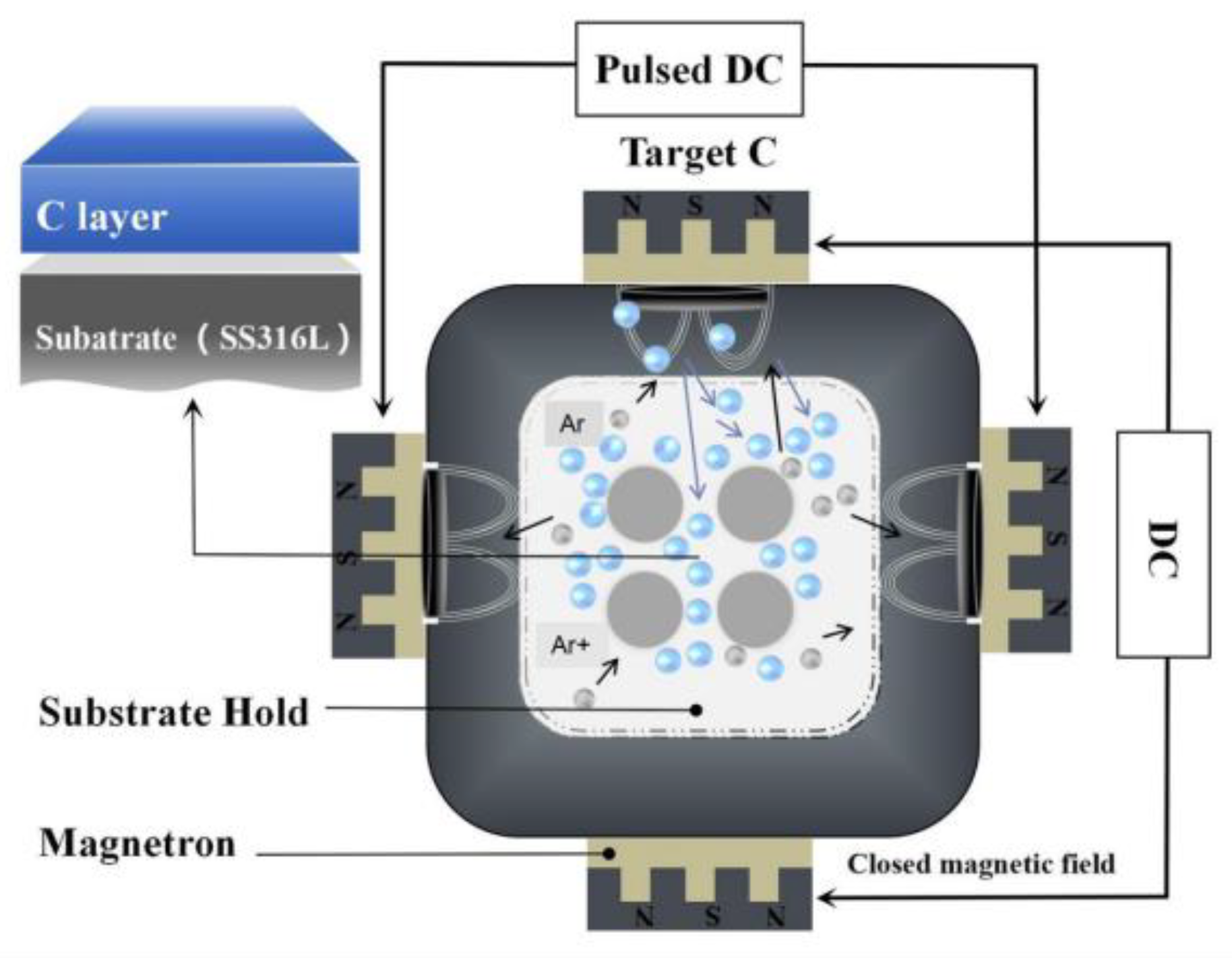
Figure 1. Fabrication process of a-C films by unbalanced magnetron sputtering on SS316L BPs.
Coatings 15 01084 g001
Figure 2. FE-SEM micrographs of cross-sectional area with EDS elemental analysis ((ai) corresponding to C1–C9 samples, respectively).
Coatings 15 01084 g002
Figure 3. Schematic model of the growth mechanism for a-C films during magnetron sputtering.
Coatings 15 01084 g003
Figure 4. XPS characterization of a-C films deposited under nine process conditions.
Coatings 15 01084 g004
Figure 5. Contact angle measurement schematic and experimental results for bare SS316L and nine a-C films: (a) Bar chart of the water contact angles of all nine coating samples (C1–C9). (b) Contact angle measurement principle and experimental results for bare SS316L. (c1c9) Optical images of water droplets on the respective a-C films (C1–C9).
Coatings 15 01084 g005
Figure 6. Potentiodynamic polarization curves of the nine a-C films (C1-C9) and the bare SS316L substrate measured in 0.5 mol/L H2SO4 solution.
Coatings 15 01084 g006
Figure 7. EIS results of the C1-C9 and the bare SS316L substrate in the 0.5 M H2SO4 + 0.1 ppm HF solution: (a) Nyquist plots, (b) the equivalent circuit model scheme, (c) the Bode impedance plots and (d) the Bode phase plots.
Coatings 15 01084 g007
Figure 8. S/N response graph for Ecorr (left), Icorr (middle), contact angle (right). (The plot shows the mean S/N ratio at each level of the four control factors: A (working pressure), B (sputtering power), C (bias voltage), and D (deposition time)).
Coatings 15 01084 g008
Table 1. Chemical composition of SS316L [2].
ComponentCSiMnPSNiCrMo
Content (%)0.0270.381.330.0350.00210.218.22.01
Table 2. Process parameters for a-C coating deposition organized via the Taguchi orthogonal design. Factor labels (letters) and level assignments (numbers) are as defined in Table 1.
SampleParameters and Levels 1
ABCD
C11111
C21222
C31333
C42123
C52231
C62312
C73132
C83213
C93321
1 Factor labels (letters) and level assignments (numbers) are as defined in Table 1.
Table 3. Deposition conditions, for carbon films, including factors and levels.
SubstrateSS316L
TargetGraphite Target
GasArgon
Substrate-to-Target Distance100 mm
Substrate Holder Rotation Frequency5 Hz
FactorProcess ParameterLevel 1Level 2Level 3
AWorking pressure
(Pa)
0.41.01.5
BSputtering power
(W)
150200250
CBias voltage
(V)
−120−200−250
DDeposition time
(min)
306090
Table 4. Electrochemical parameters obtained from potentiodynamic polarization curves in Figure 6.
SpecimensOCP
(V vs. Ag/AgCl)
Ecorr
(V vs. Ag/AgCl)
Icorr
(A/cm2)
r
(mm/y)
βa
(V/dec)
βc
(V/dec)
SS316L0.026−0.0401.58 × 10−50.1830.2040.140
C10.224−0.0361.90 × 10−60.0210.0810.177
C2−0.2570.0235.89 × 10−60.0660.1820.158
C30.007−0.2621.05 × 10−50.1190.2890.130
C40.004−0.272.88 × 10−50.3260.3150.119
C50.197−0.0132.37 × 10−50.2680.1390.197
C6−0.036−0.2989.63 × 10−60.1080.3180.144
C70.0820.051.61 × 10−60.0180.1620.200
C80.003−0.1524.30 × 10−60.0490.1710.162
C90.043−0.0116.26 × 10−60.0710.1180.252
Table 5. EIS fitting results for the nine a-C films using the equivalent circuit model.
SampleRs (Ωcm2)CPEf (F/cm2)Rf (Ωcm2)CPEdl (F/cm2)Rct (Ωcm2)
C12.685.42 × 10−811721.66 × 10−77.56 × 10⁻³
C22.436.11 × 10−811052.14 × 10−76.42 × 10⁻³
C32.562.26 × 10−79653.31 × 10−61.85 × 10⁻³
C42.781.84 × 10−79977.24 × 10−72.78 × 10⁻³
C52.952.07 × 10−79868.01 × 10−72.26 × 10⁻³
C62.411.32 × 10−710235.23 × 10−74.83 × 10⁻³
C72.545.51 × 10−812021.71 × 10−77.64 × 10⁻³
C82.615.97 × 10−811242.02 × 10−76.57 × 10⁻³
C92.759.56 × 10−810545.09 × 10−75.32 × 10⁻³
Table 6. Experimental results and S/N ratios for Ecorr, Icorr, and contact angle of the carbon films produced by magnetron sputtering.
No.Parameters and LevelsEcorrS/N (dB)Icorr (×10−6)S/N (dB)Contact AngleS/N (dB)
ABCD
C11111−0.036−11.5681.933.450107.3640.617
C212220.023−9.8165.8992.414108.9840.747
C31333−0.262−28.40410.52122.642104.2940.365
C42123−0.27−30.45828.88175.272109.8540.816
C52231−0.013−10.84223.72165.014101.2440.107
C62312−0.298−53.9799.63118.03599.8839.990
C731320.05−9.1191.6024.494106.3640.536
C83213−0.152−16.5954.3076.016100.3940.034
C93321−0.011−10.7826.2695.589101.4240.122
Table 7. The ANOVA results for the Ecorr, Icorr, and contact angle.
FactorDegree of FreedomSum of FquareVarianceContribution (P%)
Contact Angle
A228.03314.01724.01%
B253.09826.54948.36%
C234.99017.49523.16%
D22.6461.3234.48%
Total8 100
Ecorr
A20.0380.01924.49%
B20.0330.01621.41%
C20.0130.0078.76%
D20.0700.03545.34%
Total8 100
Icorr
A2497.088248.54466.83%
B210.4705.2351.41%
C2118.04259.02115.87%
D2118.23059.11515.89%
Total8 100
Table 8. The evaluation of comprehensive performance for Taguchi design of experiments.
No.123456789
Comprehensive Performance0.8030.4780.1030.0480.3720.0930.9950.3650.443
Disclaimer/Publisher’s Note: The statements, opinions and data contained in all publications are solely those of the individual author(s) and contributor(s) and not of MDPI and/or the editor(s). MDPI and/or the editor(s) disclaim responsibility for any injury to people or property resulting from any ideas, methods, instructions or products referred to in the content.