Article

Rotating Bending Fatigue Properties of 30CrNi2Mo Steel After Electropulsing-Assisted Ultrasonic Surface Rolling Process

1
Northwest Institute of Mechanical & Electrical Engineering, Xianyang 712099, China
2
Institute of Mechanical Engineering, Zhejiang University, Hangzhou 310030, China
3
School of Materials Science and Engineering, Xi’an University of Technology, Xi’an 710048, China
*
Authors to whom correspondence should be addressed.
Coatings 2025, 15(9), 1075; https://doi.org/10.3390/coatings15091075
Submission received: 15 July 2025 / Revised: 8 September 2025 / Accepted: 9 September 2025 / Published: 12 September 2025
(This article belongs to the Section Surface Characterization, Deposition and Modification)

Abstract

With the rapid development of mechanical components, increasingly stringent demands are placed on steel properties—particularly tensile strength and rotating bending fatigue resistance. This study systematically investigates the effects of the electropulsing-assisted ultrasonic surface rolling process (EUSRP) on the surface microstructure and fatigue performance of 30CrNi2Mo steel. A fine-grained surface layer (depth: 80 μm) was formed. Lath martensite width decreased significantly from 7 μm to 4 μm after EUSRP treatment, which was significantly refined after electropulsing treatment and an ultrasonic surface-rolling process. Under identical stress amplitudes, the rotating bending fatigue life of EUSRP-treated specimens substantially exceeded that of the as-machined state. Fatigue cracks in the as-machined state consistently initiated at the surface, coalesced, and propagated into large cracks, leading to premature fracture. In EUSRP-treated samples, crack initiation shifted to subsurface regions, delaying failure and extending fatigue life.

1. Introduction

Steel of the 30CrNi2Mo type is a low-alloy structural steel known for its excellent mechanical properties and high-temperature strength. It is widely used in applications such as automobile engine crankshafts, planetary gears, transmission shafts, etc. [1]. With the rapid development of manufacturing technologies and the increasing demand for wear resistance, more stringent requirements have been imposed on the service performance of materials such as steel, including strength, ductility, and fatigue resistance.
Generally, fatigue cracks tend to initiate easily from the surface of materials in a structural component [2,3]. It has been reported that the enhancement of surface strength can increase the fatigue strength of the component [4]. Introducing a stronger material layer onto the surface is an effective method to enhance the surface strength of components. Research has shown that the use of coatings prepared by thermal spraying technology, chemical deposition technology, and magnetron sputtering technology [5,6] significantly improves the wear resistance and service life of steel parts [7,8]. However, these coatings often suffer from poor adhesion, making them prone to peeling off. Therefore, it is crucial to find surface modification technologies with strong adhesion and excellent performance.
In order to improve the surface property, shot peening [3,4,9] and the ultrasonic surface rolling process (USRP) [10] are commonly used. It has been reported that a smooth surface layer (high surface quality) with high microhardness was generated, which significantly increased the surface hardness, wear resistance [11,12] and fatigue life [13] of steel specimens. The fatigue properties of steels are significantly influenced by the surface morphology and microstructure. It has been found that microstructures such as retained austenite and incompletely hardened microstructures affect the fatigue strength of steels [14]. In recent years, researchers have discovered that the application of high-energy pulse currents—known as electropulsing treatment (EP)—can not only enhance the plasticity of the metal material, but also cause a rapid crystallization and grain size refinement due to the Joule heating effect [15,16]. High-energy electric pulses can rapidly transfer energy to the region that satisfies phase transition, achieving selective and rapid heating of materials. This contrasts with traditional heat treatment processes, which rely on global thermal conduction to achieve phase transformation [17,18]. Previous research has shown that a pulsed current can promote recrystallization nucleation and induce phase transformation [17,19,20].
Therefore, the integration of electropulsing with the ultrasonic surface rolling process referred to as the electropulsing-assisted ultrasonic surface rolling process (EUSRP) is a promising green manufacturing technology that can effectively realize the surface strengthening of steel. Therefore, this article focuses on the machining state and systematically studies the influence of EUSRP on the surface microstructure and fatigue properties of 30CrNi2Mo steel. The changes in surface microstructure and fatigue properties are explored through methods such as optical microscopy (OM), scanning electron microscopy (SEM), and electronic universal testing machines. This research is of significant importance in extending the service life of critical engineering components, such as pipeline materials.

2. Materials and Methods

Steel of the type 30CrNi2Mo is a medium carbon, low-alloy quenched and tempered steel that has undergone the final treatment, including quenching at 870 °C, primary tempering at 580 °C, and secondary tempering at 620 °C. The composition of 30CrNi2Mo steel consists of 0.3%C, 0.35%Si, 0.43%Mn, 1.5%Cr, 1.0%Mo, 2.02%Ni, 0.03%Nb, 0.24%V, and 0.04%Cu. The material was machined into short rod samples with a diameter of 16 mm and a length of 200 mm for surface microstructural analysis. The changes of surface microstructure were investigated by metallographic observation. The sample was mechanically ground with #180, #300, #600, #800, #1200, and #1500 sandpaper, and then polished with 0.5 μm diamond polishing solution to mirror without scratches. The KH-7700 3D (HRIOX, Japan) and Olympus GX71 optical microscope (Olympus, Japan) were used to carry out observations on the sample’s surface morphology.
The bending fatigue performance of 30CrNi2Mo was assessed with a rotating bending fatigue testing machine (PQ60, China) with a maximum force of 10KN, a stress ratio R of −1, and a loading frequency of 50 HZ. The rotating bending fatigue was carried out according to the standard of GB/T4337-2015 [21]. The dimension of the fatigue sample is shown in Figure 1. In order to compare the fatigue life of two types of microstructure under the same stress amplitude, the stress amplitudes of 740 MPa, 700 MPa, 620 MPa, 550 MPa, 500 MPa, 450 MPa, 400 MPa, and 360 MPa were selected. The stress amplitude cycle (S-N) curve was obtained by the comparison of fatigue life under the same stress amplitude. One to two samples were tested under every stress amplitude, which is similar to Ref. [22]. After unloading, the morphology of the indentation surface was observed using a Keyence depth of field stereomicroscope. If the force displacement curve decreased during the process, the experiment was stopped, otherwise the sample would fracture. The ablation experiment was conducted on a self-developed ablation simulation test device. Under the same test conditions and number of tests, the weight changes of the specimens before and after the experiment were compared, and the surface structure was observed by SEM (ZEISS Merlin Compact, Germany).

3. Results and Discussion

3.1. Surface Microstructure

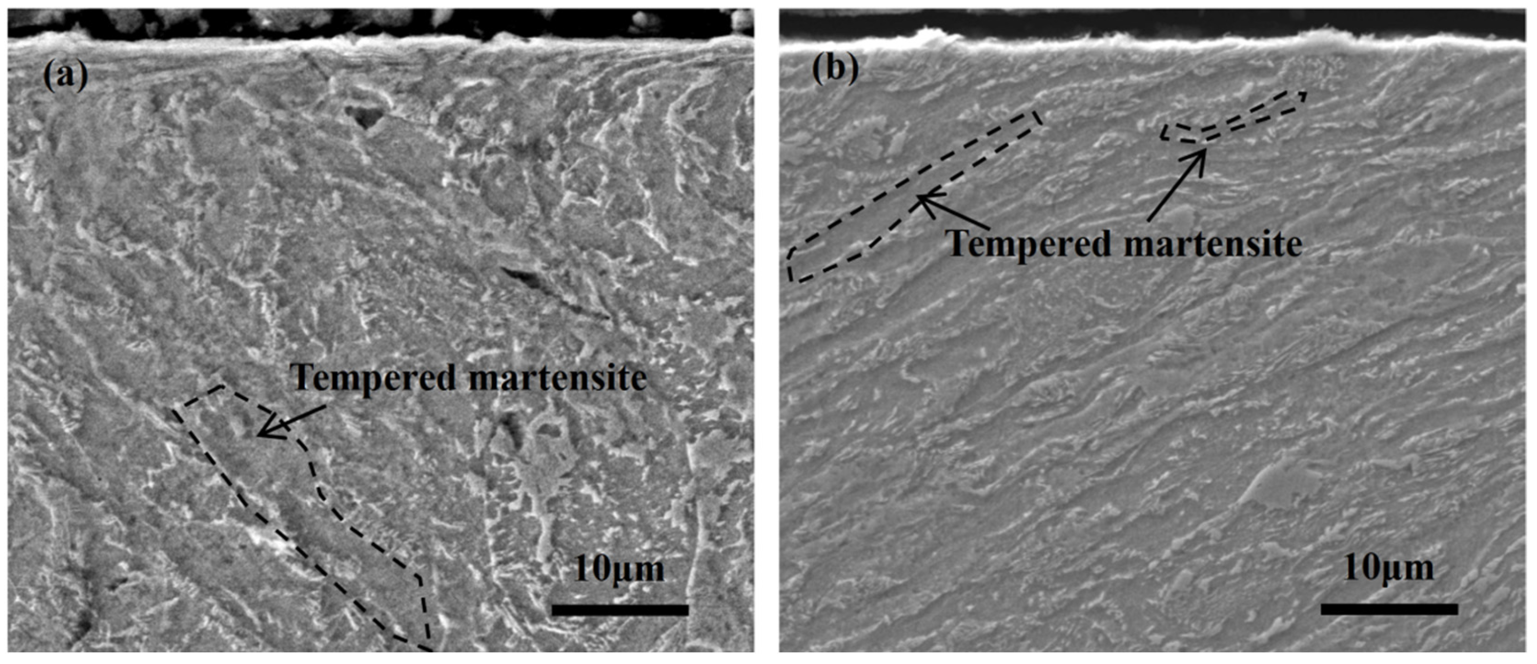
Figure 2a presents the metallographic morphology of the machining state of 30CrNi2Mo steel. The microstructure primarily consists of tempered martensite, residual austenite, and a small amount of pearlite, with little difference in surface and near surface microstructure. The tempered martensite with a width of about 7 μm was observed. However, due to the implementation of electric pulse heating, the amount of martensite and residual austenite was significantly reduced for the EUSRP sample, as shown in Figure 2b. Moreover, it was reported that strain-induced martensitic transformation after the electropulsing-assisted ultrasonic surface rolling process was found in 9310 steel, which led to the refinement of the microstructure [23].
Figure 3a shows the cross-sectional microstructure of the machining state of 30CrNi2Mo steel, which consists of tempered martensite, residual austenite, and a small amount of pearlite. The surface and near surface microstructures are not significantly different. Figure 3b shows the cross-sectional microstructure morphology of the EUSRP of 30CrNi2Mo steel. In addition to the fine-grain structure layer with a depth of 80 μm, the width of lath martensite is refined to about 4 μm. It can be seen that compared to the machining state, the grain size of the alloy was significantly refined after electropulsing-assisted ultrasonic surface rolling processing. Yin et al. [24] found that compared to conventionally cold-rolled counterparts, electrical pulse-assisted cold ring rolling exhibited significantly refined microstructures, characterized by the formation of numerous subgrains within parent ferrite grains. The electric pulse can enhance the recrystallization rate, so the nanocrystalline layer can be easily produced [25]. This microstructural refinement is attributed to the accelerated recrystallization induced by the applied electrical pulses, which promote dislocation mobility and reduce nucleation energy barriers.

3.2. Mechanical Properties of Steel

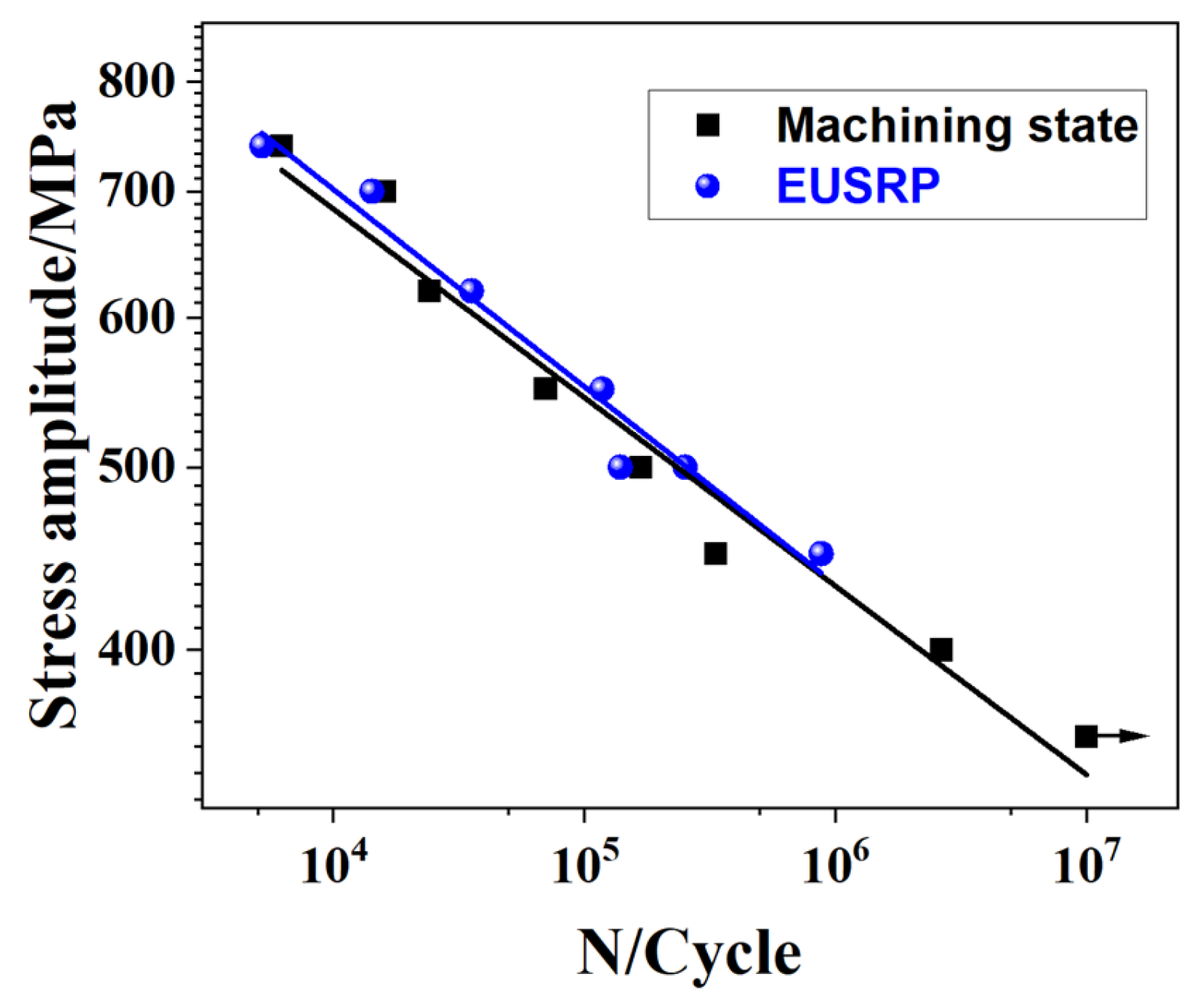
The yield strength, tensile strength, elongation, and yield to strength ratio of the machining state specimen were 730 MPa, 955 MPa, 31%, and 0.764, respectively [26]. The yield strength, tensile strength, elongation, and yield to strength ratio of the EUSRP of the 30CrNi2Mo steel specimen were 738 MPa, 946 MPa, 10%, and 0.78, respectively. Figure 4 is the curve between the rotating bending stress amplitude and the number of cycles of 30CrNi2Mo steel. It can be seen that as the stress amplitude increased, the rotating bending fatigue life significantly decreased. Only when the stress amplitude was 360 MPa could the rotating bending fatigue life of the machining state exceed 10 million cycles without fracture. However, as the stress amplitude increased, the rotating bending fatigue life of the electropulsing-assisted ultrasonic surface rolling process sample (EUSRP) was generally higher than that of the machining state specimen. The fatigue life of the machining state was 333,087, 70,000, and 24,275 cycles at stress amplitudes of 450 MPa, 550 MPa, and 620 MPa, respectively. Meanwhile, the fatigue life increased to 877,065, 117,339, and 35,516 cycles at the same stress amplitude for EUSRP samples of 450 MPa, 550 MPa, and 620 MPa, respectively, as shown in Table 1. This indicates that the rotating bending fatigue life of the EUSRP sample was higher than that of the machining state under the same stress amplitude.

3.3. Fracture Morphology

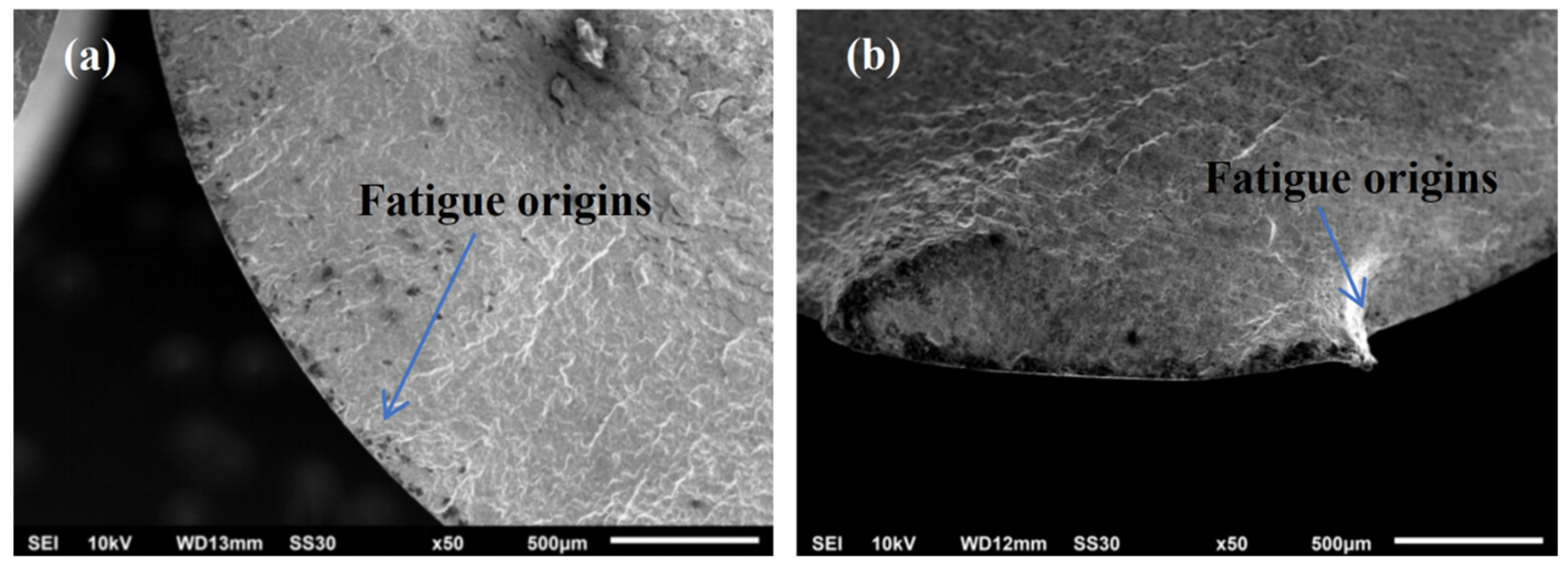
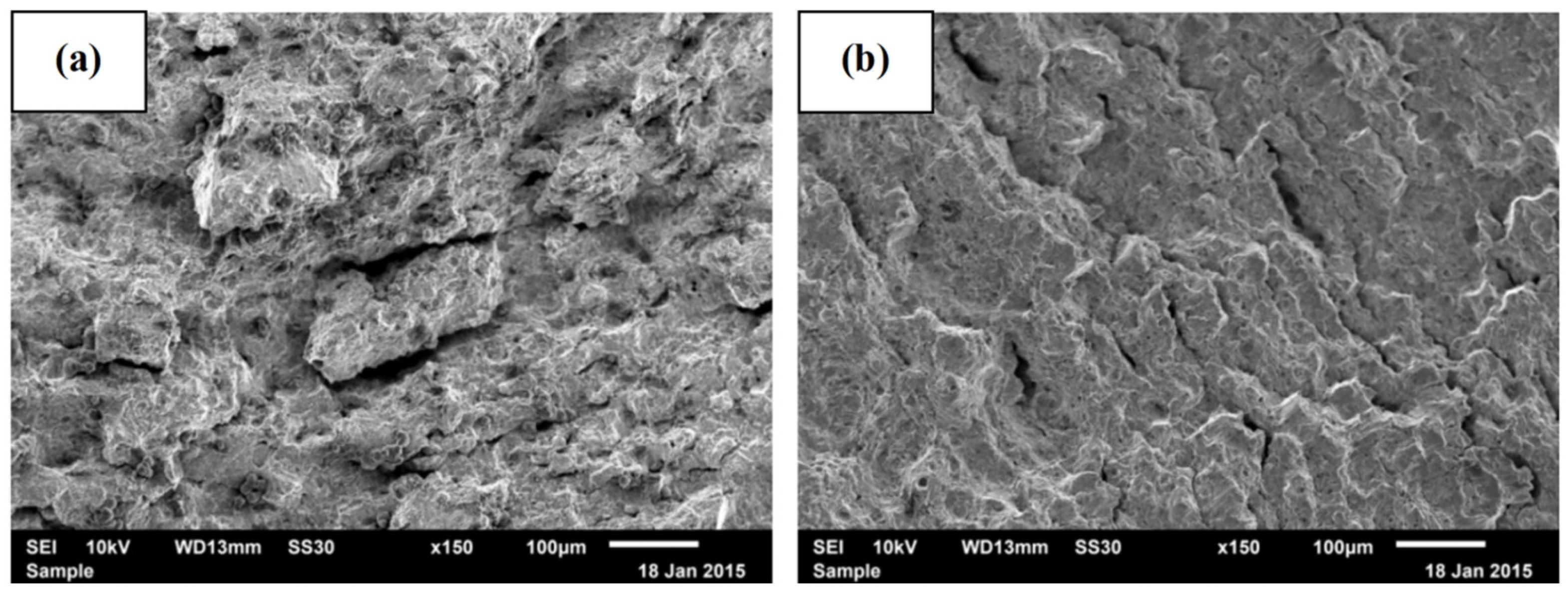
In order to reveal the rotating bending fatigue damage mechanism of 30CrNi2Mo material, comparative studies were conducted on the fatigue fracture and crack initiation characteristics under stress amplitudes of 620 MPa, 550 MPa, and 450 MPa. Figure 5 shows the rotating bending fatigue fracture morphology characteristics of 30CrNi2Mo as the machining state under different stress amplitudes. It can be seen that the fatigue fracture surfaces exhibited brittle fracture characteristics without obvious plastic deformation features. All fatigue fracture surfaces exhibited the initiation zone of rotating bending fatigue cracks, which was reported in Refs. [27,28]. As the stress amplitude increased, all rotating bending fatigue cracks initiated from the surface of the specimen, and at least two or more rotating bending fatigue crack source regions appeared, as shown in Figure 5. Specifically, under high stress amplitudes such as 550 MPa (Figure 5a), multiple rotating bending fatigue crack initiation sites were observed in the material. These cracks originated simultaneously from different regions on the surface, significantly intensifying the extent of fatigue damage and resulting in a shorter fatigue life (Figure 4). In contrast, under lower stress amplitudes (Figure 5b, 450 MPa), only a single rotating bending fatigue source region was observed. It is generally accepted that the interaction and coalescence of multiple rotating bending fatigue source regions accelerate crack propagation and final fracture. As shown in Figure 5, with increasing stress amplitude, the number of crack initiation sites increased, intensifying the interaction among them and consequently reducing the fatigue life. This trend is consistent with the observed rotating bending fatigue life behavior of the material.
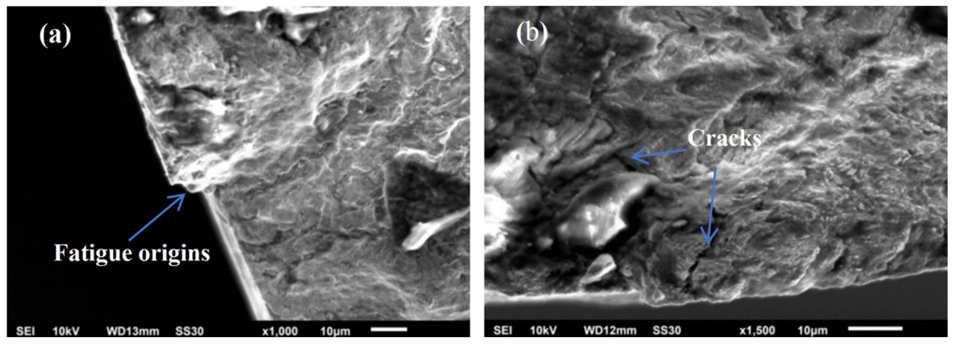
In order to further analyze the mechanism of rotating bending fatigue fracture, the initiation zone of rotating bending fatigue cracks was specifically enlarged in the specimens under different stress amplitudes to observe and analyze the detailed information. Figure 6 shows the characteristics of the rotating bending fatigue crack initiation zone of the machining state under low and high stress amplitudes. Figure 6a shows that under a stress amplitude of 550 MPa, fatigue cracks originated on the surface of the material and led to the formation of extruded bands on the surface, forming a “Z” shaped step. Under the lower stress amplitude of 450 MPa, although the fatigue cracks of the alloy still initiated on the surface of the material, it exhibited the characteristics of interconnected propagation of microcracks, as shown in Figure 6b. Fracture surfaces contained multiple cracks and crack initiation sites in the surface area, which led to the low fatigue life [24].
Figure 7 shows the rotating bending fatigue fracture morphology of acoustic–electric coupling state steel under different stress amplitudes. It can be seen that two larger fatigue sources were generated at 620 MPa, one larger crack source was generated at 550 MPa, and three smaller crack sources were generated at 450 MPa. Rotating bending fatigue cracks occurred on the surface and near the surface of the specimen, and then propagated into the material in a river-like pattern, forming a fan-shaped feature. Moreover, the higher the stress amplitude, the more pronounced the surface roughness, indicating that cyclic deformation and crack interaction in the alloy became more intense under elevated stress levels, resulting in more severe fatigue damage. It can be concluded that rotating bending fatigue cracks all occurred near the surface of the specimen, and then propagated into the material in a river-like pattern, forming a fan-shaped feature, as shown in Figure 7a–c. With the increasing stress, the surface roughness became more significant, leading to phenomena such as steps on the surface. Fatigue cracks originated at a position of 13 μm near the surface at a stress amplitude of 620 MPa, as shown in Figure 7a. Under the stress amplitudes of 550 MPa and 450 MPa, rotating bending fatigue cracks were primarily initiated at distances of approximately 15 μm and 22 μm from the surface of the alloy, respectively, before propagating inward, as illustrated in Figure 7b,c.

3.4. Fatigue Crack Initiation and Growth

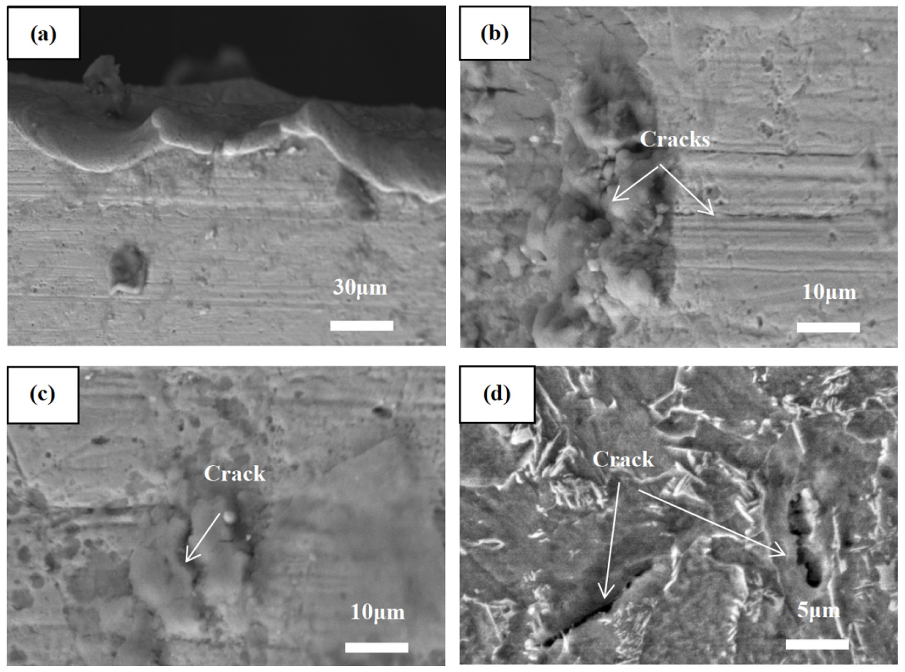
In this study, the formation of fatigue cracks was significantly influenced by the interaction between rotating bending cyclic loading and surface fine-grain structure. In order to reveal the mechanism of rotating bending fatigue crack initiation, detailed observation and analysis were conducted on the surface morphology characteristics of the fatigue crack initiation site. Figure 8 shows the rotating bending fatigue crack initiation morphology of machining state material under a stress amplitude of 550 MPa. The crack propagation path exhibited micro area twists and turns, with a microscopic rise of about 20 μm, as shown in Figure 8a. A large number of microcracks formed on the surface beneath the fatigue crack initiation zone. Once a crack nucleated, adjacent microcracks tended to coalesce, forming larger cracks. As illustrated in Figure 8b, fatigue cracks originated on the surface of the material and were relatively flat with almost no unevenness. These flat cracks were likely to accelerate the rate of crack propagation, thereby reducing fatigue life. In addition, the presence of larger grain boundaries and martensitic interfaces in the as machined microstructure also became the preferred locations for fatigue crack initiation, as shown in Figure 8c,d. These crack initiation characteristics are not conducive to improving fatigue life and have become the main reason for low fatigue life in the machining state.
Figure 9 shows the micrograph of the fatigue crack initiation zone of the acoustic electric coupled state alloy under a stress amplitude of 550 MPa. Compared with the machining state of 30CrNi2Mo (Figure 8), the crack initiation site of the alloy after acoustic–electric coupling treatment was located near the surface. In the acoustic–electric coupling condition, fatigue cracks initiated at a depth of approximately 15 μm from the surface and tended to form at phase interfaces. These cracks subsequently interconnected and propagated within the grain boundary, as shown in Figure 9a. On the near surface, the fatigue microcracks of the alloy were relatively flat, with a combined amplitude of about 3 μm, which was an improvement compared to the machining state, as shown in Figure 9b. With the increase of cyclic deformation, in addition to observing obvious cyclic deformation, such as the twisting and rotating bending deformation of martensite, fatigue microcracks were formed during its cyclic squeezing into the extrusion band, and they were easily connected to each other (Figure 9c).
From the above results, it can be concluded that micro cracks at the interface could propagate and coalesce with neighboring microcracks along the interface, leading to the formation of larger cracks. In addition, the interfaces between martensite and residual austenite were particularly susceptible to fatigue crack initiation. Once formed, these microcracks interconnected with adjacent cracks, eventually evolving into large-scale, long cracks. As indicated by the observations, once crack initiation occurred, continued cyclic loading promoted the merging and interconnection of fatigue cracks, ultimately resulting in the formation of macroscopic cracks.
Figure 10 shows the interconnected fatigue crack propagation characteristics of the machining state under different stress amplitudes. By observing the morphology of the fatigue crack propagation area, it can be seen that during the rotating bending fatigue process, obvious rough surfaces and secondary cracks were also observed on the fracture surface at 620 MPa (Figure 10a), and the secondary cracks showed relatively straight characteristics. Notably, at a stress amplitude of 620 MPa, the increased number of surface-initiated cracks and their subsequent interconnection promoted crack propagation. Moreover, under high stress amplitudes, tearing edges and step-like features became more pronounced and densely distributed, indicating a stronger interaction between cracks. Once initiated, cracks readily coalesced and interconnected, leading to the rapid formation of large-scale cracks. At a relatively low stress of 550 MPa, the size and number of secondary fatigue cracks were reduced, and the unevenness of the fracture surface was also alleviated (Figure 10b).
As indicated by the observations, more tearing edges were observed on the fracture surface for the machining state specimens, which suggests that under higher stress, more main cracks grow simultaneously. In general, during rotating bending fatigue, multiple cracks may initiate simultaneously and connect with one another during crack propagation, ultimately forming a single large crack. The presence of numerous tearing edges and steps on the fracture surface indicates that there are more cracks growing simultaneously under high stress amplitudes. This suggests that high stress amplitudes promote the propagation of surface microcracks towards the center, as shown in Figure 5 and Figure 6.
Figure 11 shows the rotating bending fatigue crack propagation behavior of 30CrNi2Mo acoustic–electric coupled steel under different stress amplitudes. As shown in Figure 11a, the fracture morphology of the rotating bending fatigue crack propagation region of the steel appears relatively rough, with large and relatively straight secondary cracks observed at 620 MPa. The tortuous height is about 20 μm. Tearing edges and steps can be observed. Microcracks tended to nucleate at the phase interface and could easily propagate and coalesce through fractured grains, thereby accelerating the crack propagation rate to some extent. As shown in Figure 11b, a smaller number of microcracks can be observed under a lower stress of 550 MPa compared to the machining state. Consequently, the fatigue life was slightly improved in the acoustic–electric coupling state relative to the machining state.
Figure 12 presents a schematic diagram of crack initiation for two types of specimens. In the machining state, the lath martensite was randomly distributed, offering the lowest resistance to crack initiation during rotary bending fatigue. Under cyclic stress, dislocation slip bands were prone to form in the coarse grains on the surface of the 30CrNi2Mo machined specimens. During further loading, residual slip bands led to surface compression and intrusion. Under subsequent rotating bending cyclic stress, fatigue cracks initiated at the sites of surface undulations and phase interfaces, and then propagated by interconnecting with neighboring cracks to form larger cracks, thereby accelerating the fracture failure of the alloy. Crack initiation occurred more readily on the specimen surface, exhibiting characteristics of multiple crack sources, as illustrated in Figure 12a.
After EUSRP treatment, the surface grains of the sample were refined and exhibited gradient characteristics (Figure 12b). Additionally, the volume and size of residual austenite was reduced due to the stress-induced transformation. This phenomenon has been reported in Ref. [22]. The fine grains on the surface had a certain inhibitory effect on crack initiation, and the fatigue cracks of the rotary bending occurred near the surface of the sample, which is beneficial to the improvement of fatigue life.
Yin et al. [23] found that compared to conventionally cold-rolled counterparts, electrical pulse-assisted cold ring rolling M50 rings subjected to a pulsed current exhibited significantly refined microstructures, characterized by the formation of numerous subgrains within parent ferrite grains. The electric pulse can promote the recrystallization rate, so the nanocrystalline layer can be easily produced [24], which is consistent with our experiment results (Figure 2 and Figure 3). This microstructural refinement is attributed to the accelerated recrystallization induced by the applied electrical pulses, which promote dislocation mobility and reduce nucleation energy barriers. The fatigue life of Ti6Al4V ELI alloy can be improved by about 25 times at 780 MPa using the electropulsing-assisted ultrasonic surface rolling process. The main reason for the highest fatigue life is the deepest surface gradient layer and the deepest crack initiation site [29]. Compared to the machining state, the fatigue crack origins occurs at the subsurface, about 13–22 μm away from the surface, as shown in Figure 7. It has been reported that the fatigue properties are improved owing to the smooth surface, higher compressive residual stress, and the nanocrystallization layer during electropulsing-assisted ultrasonic rolling processing [30]. Due to the recrystallization and strain-induced martensitic transformation resulting from the electropulsing-assisted ultrasonic surface rolling process, it was found that the grain size of the surface layer decreased, and the content of retained austenite in the surface layer decreased, collectively contributing to significant improvements in surface properties in 9310 steel [22]. Similar results are observed in the present work (Figure 3b). Furthermore, it was found that the fatigue striation width decreased by 48.6%, 62.5%, and 69.4% for samples receiving one, three, and five ultrasonic rolling passes, respectively [31], which indicates that crack retardation occurred to improve the fatigue life. It was concluded that the depth of the hardened and compressive residual stress layers was significantly increased by the electropulsing-assisted ultrasonic surface rolling treatment [22]. Based on the above results, it can be seen that crystallization, strain-induced martensitic transformation, and compressive residual stress could be induced during the electropulsing-assisted ultrasonic surface rolling process, which is beneficial to the improvement of fatigue life. Therefore, the fatigue life of the acoustic–electric coupling state is slightly higher than that of the turning state.

4. Conclusions

(1) The microstructure of 30CrNi2Mo steel for the machining state is represented by tempered martensite, residual austenite, and a small amount of pearlite. In this case, tempered martensite has a slat morphology. The transverse dimensions of the slats are about 7 μm. After ultrasonic surface rolling with electric pulse treatment, in addition to a fine-grained structure layer 80 μm deep, the transverse dimensions of the tempered martensite slats decrease to about 4 μm.
(2) As the stress amplitude increases, the fatigue performance of 30CrNi2Mo decreases for both the machining state and EUSRP-treated samples. However, under the same stress amplitude, the rotating bending fatigue life of the EUSRP sample is significantly improved, ranging from 1.46 to 2.63 times higher than that of the machining state.
(3) For the machining state, fatigue cracks are prone to initiate on the material surface of the material, where they propagate and interconnect to form large cracks, ultimately leading to fatigue fracture. In contrast, for EUSRP-treated samples, the fatigue cracks initiation tends to occur near or on the subsurface, which contributes to the enhanced fatigue life due to the refined grain structure and modified surface properties.

Author Contributions

Conceptualization, C.T.; methodology, D.L.; validation, H.H.; formal analysis, H.F. and Y.K.; investigation, H.H., Y.S., J.L. and H.F.; data curation, D.L. and H.F.; writing—original draft preparation, D.L., C.T. and H.F.; writing—review and editing, Y.S. and J.L.; project administration, H.H. All authors have read and agreed to the published version of the manuscript.

Funding

This work was funded by the Scientific Research Foundation of Northwest Institute of Mechanical & Electrical Engineering, grant number 2024-XYY-600407-0009, the National Natural Science Foundation of China, grant number 52001261 and the Technology Innovation Leading Program of Shaanxi, grant number 2024ZCYYDP92.

Institutional Review Board Statement

Not applicable.

Informed Consent Statement

Not applicable.

Data Availability Statement

The data that have been used are confidential. If necessary, you can contact the first author or corresponding author.

Conflicts of Interest

The authors declare no conflicts of interest.

References

  1. Yang, K.; Lv, X.M.; Wang, B.; Lai, Z.; Chen, X.; Wei, D.; Li, S.; Zhang, P. Microstructure and Wear Performance of TaC and Ta/TaC Coatings on 30CrNi2MoVA Steel. Coatings 2024, 14, 1039. [Google Scholar] [CrossRef]
  2. Zhang, L.; Song, Y.; Wang, X.; Zhou, S.; Ding, Z.; Jin, W.; Gao, Z.; Jiang, Y. A study of fatigue property enhancement of 1045 steel processed by surface mechanical rolling treatment with an emphasis on residual stress influence. Int. J. Fatigue 2024, 189, 108560. [Google Scholar] [CrossRef]
  3. Soyama, H.; Wong, K.L.; Eakins, D.; Korsunsky, A.M. The effects of submerged laser peening, cavitation peening, and shot peening on the improvement of the torsional fatigue strength of powder bed fused Ti6Al4V produced through laser sintering. Int. J. Fatigue 2024, 185, 108348. [Google Scholar] [CrossRef]
  4. Li, J.; Wang, L.; Wang, X.; Hu, Z. Effect of shot peening equivalent impact force on fatigue crack growth behavior and fatigue life prediction of train brake discs. Eng. Fail. Anal. 2024, 166, 108914. [Google Scholar] [CrossRef]
  5. Bielawski, M. Hard chromium plating alternative technologies. Can. Aeronaut. Space J. 2000, 46, 140–149. [Google Scholar]
  6. Vander, G.J.; Fleischer, W.; Eerden, M.; Hurmans, T. PVD coating as alternative to electroplated chromium. Galvanotechnik 2001, 92, 3058–3066. [Google Scholar]
  7. Hu, M.; Tang, Y.Y.; Han, X.; Guo, C.; Lu, X.; Pan, M. Failure behavior of Cr coating on PCrNi3MoVA steel under thermal-mechanical factors. Mater. Chem. Phys. 2024, 312, 128691. [Google Scholar] [CrossRef]
  8. Han, X.; Hu, M.; Tang, Y.Y.; Gao, P.; Gao, Y.; Li, Z. Thermal erosion behavior of electroplating and multi-arc ion plating Cr coatings on PCrNi3MoVA steel. J. Phys. Conf. Ser. 2024, 2921, 012003. [Google Scholar] [CrossRef]
  9. Xu, C.; Wang, X.; Geng, Y.; Wang, Y.; Sun, Z.; Yu, B.; Tang, Z.; Dai, S. Effect of shot peening on the surface integrity and fatigue property of gear steel 16Cr3NiWMoVNbE at room temperature. Int. J. Fatigue 2023, 172, 107668. [Google Scholar] [CrossRef]
  10. Zhang, Y.; Wu, L.; Shi, D.; Wang, Z.; Jin, H.; Liu, L.; Qu, S.; Ji, V. Surface integrity and tribological behavior of 17Cr2Ni2MoVNb steel under combined carburizing treatment and ultrasonic rolling. Surf. Coat. Technol. 2023, 461, 129371. [Google Scholar] [CrossRef]
  11. Zhang, Q.; Hu, Z.; Su, W.; Zhou, H.; Liu, C.; Yang, Y.; Qi, X. Microstructure and surface properties of 17—4PH stainless steel by ultrasonic surface rolling technology. Surf. Coat. Technol. 2017, 321, 64–73. [Google Scholar] [CrossRef]
  12. Wang, P.; Guo, H.; Wang, D.; Duan, H.; Zhang, Y. Microstructure and tribological performances of M50 bearing steel processed by ultrasonic surface rolling. Tribol. Int. 2022, 175, 107818. [Google Scholar] [CrossRef]
  13. Torres, M.A.; Voorwald, H.J. An evaluation of shot peening, residual stress and stress relaxation on the fatigue life of AISI 4340 steel. Int. J. Fatigue 2002, 877, 877–886. [Google Scholar] [CrossRef]
  14. Kikuchi, M.; Komine, A.; Kibayashi, Y. Influence of internal oxides on the fatigue strength of carburized steel. J. Soc. Mater. Sci. 1989, 38, 111–116. [Google Scholar] [CrossRef]
  15. Yang, C.L.; Yang, H.J.; Zhang, Z.J.; Zhang, Z.F. Recovery of tensile properties of twinning-induced plasticity steel via electropulsing induced void healing. Scr. Mater. 2018, 147, 88–92. [Google Scholar] [CrossRef]
  16. Tan, C.; Yang, T.; Huang, C.; Zhang, J.; Wang, X.; Lu, H.; Wen, L.; Zhang, G. Enhanced strength–ductility synergy in Ti55531 titanium alloys through gradient microstructural design strategy. Mater. Sci. Eng. A 2024, 909, 146823. [Google Scholar] [CrossRef]
  17. Bao, T.; Tan, C.; Huang, C.; Li, Q.; Fan, Y.; Zhang, G.; Guo, P. Multiscale microstructure regulation and synergistic strengthening mechanisms in Ti-6Al-4V alloy via electropulsing treatment. J. Alloys Compd. 2025, 1035, 181526. [Google Scholar] [CrossRef]
  18. Zhou, Y.; Xu, X.; Zhao, Y.; Yan, X.; Wei, L.; Wu, Z.; Wu, C. Introducing ω and O′ nanodomains in Ti-6Al-4V: The mechanism of accelerating α→ β transformation kinetics via electropulsing. J. Mater. Sci. Technol. 2023, 162, 109–117. [Google Scholar] [CrossRef]
  19. Chen, K.; Zhan, L.; Yu, W. Rapidly modifying microstructure and mechanical properties of AA7150 Al alloy processed with electropulsing treatment. J. Mater. Sci. Technol. 2021, 95, 172–179. [Google Scholar] [CrossRef]
  20. Gao, J.B.; Ben, D.D.; Yang, H.J.; Meng, L.; Ji, H.; Lian, D.; Chen, J.; Yi, J.; Wang, L.; Li, P.; et al. Effects of electropulsing on the microstructure and microhardness of a selective laser melted Ti6Al4V alloy. J. Alloys Compd. 2021, 875, 160044. [Google Scholar] [CrossRef]
  21. GB/T4337-2015; Metallic Materials—Fatigue Testing—Rotating Bar Bending Method. National Standard of the People’s Republic of China: Beijing, China, 2015.
  22. Duan, C.; Qu, S.; Hu, X.; Jia, S.; Li, X. Microstructures and fatigue behaviors of 25CrNi2MoV steel under electropulsing-assisted ultrasonic surface rolling. Int. J. Fatigue 2022, 158, 106733. [Google Scholar] [CrossRef]
  23. Gao, M.; Zeng, R.; Hu, J.; Zhang, C.; Hu, X.; Xia, S.; Huang, R.; Li, Q. Further enhancement of surface mechanical properties of carburized 9310 steel by electropulsing-assisted ultrasonic surface rolling process. Surf. Coat. Technol. 2024, 480, 130593. [Google Scholar] [CrossRef]
  24. Yin, F.; Yi, Y.; Chen, Y.; Cheng, G.J.; Hua, L. Understanding the mechanisms of microstructure refinement and plasticity enhancement of M50 bearing steel fabricated by the electrical pulse assisted cold ring rolling technology. J. Mater. Res. Technol. 2025, 36, 3906–3920. [Google Scholar] [CrossRef]
  25. Ji, R.; Yang, Z.; Jin, H.; Liu, Y.; Wang, H.; Zheng, Q.; Cheng, W.; Cai, B.; Li, X. Surface nanocrystallization and enhanced surface mechanical properties of nickel-based superalloy by coupled electric pulse and ultrasonic treatment. Surf. Coat. Technol. 2019, 375, 292–302. [Google Scholar] [CrossRef]
  26. Liu, D.; Ke, Y.; Huang, H.; Tan, C.; Xu, Q.; Li, H. Improvement of Surface Properties of 30CrNi2MoVA Steel with Ultrasonic Composite Strengthening Modification. Coatings 2025, 15, 183. [Google Scholar] [CrossRef]
  27. Wang, H.; Dang, E.; Jiang, S.; Fan, Y.; Tan, C. Corrosion Fatigue Failure Mechanism of Steels for Hydraulic Fracturing Pump Valve Box. J. Mater. Eng. Perform. 2025, 34, 4217–4229. [Google Scholar] [CrossRef]
  28. Kermajani, M.; Ghaini, F.M.; Miresmaeili, R.; Baghi-Abadi, M.; Mousavi-Nasab, M. Damage mechanisms in the ultra-low cycle fatigue loading. Eng. Fract. Mech. 2020, 223, 106772. [Google Scholar] [CrossRef]
  29. Sun, P.; Qu, S.; Duan, C.; Hu, X.; Li, X. Improving the high cycle fatigue property of Ti6Al4V ELI alloy by optimizing the surface integrity through electric pulse combined with ultrasonic surface rolling process. J. Mater. Sci. Technol. 2024, 170, 103–121. [Google Scholar] [CrossRef]
  30. Qu, S.; Ren, Z.; Hu, X.; Lai, F.; Sun, F.; Li, X.; Yang, C. The effect of electric pulse aided ultrasonic rolling processing on the microstructure evolution, surface properties, and fatigue properties of a titanium alloy Ti5Al4Mo6V2Nb1Fe. Surf. Coat. Technol. 2021, 421, 127408. [Google Scholar] [CrossRef]
  31. Cong, J.; Gao, J.; Zhou, S.; Wang, N.; Wang, J.; Hui, L. Effect of ultrasonic rolling on crack propagation behavior of Ti6Al4V titanium alloy laser welded joints. Eng. Fract. Mech. 2023, 292, 109618. [Google Scholar]
Figure 1. Dimensions of the samples (unit: mm).
Coatings 15 01075 g001
Figure 2. Microstructure of a 30CrNi2Mo specimen: (a) machining state, (b) EUSRP.
Coatings 15 01075 g002
Figure 3. Cross-sectional microstructure of 30CrNi2Mo steel samples: (a) machining state, (b) EUSRP.
Coatings 15 01075 g003
Figure 4. Rotating bending fatigue properties of 30CrNi2Mo steel.
Coatings 15 01075 g004
Figure 5. Rotating bending fatigue fracture morphology of 30CrNi2Mo as turned material under different stress amplitudes: (a) 550 MPa, (b) 450 MPa.
Coatings 15 01075 g005
Figure 6. Characteristics of rotating bending fatigue crack source zone of the machining state: (a) 550 MPa, (b) 450 MPa.
Coatings 15 01075 g006
Figure 7. Characteristics of the rotating bending fatigue crack source region in EUSRP under different stress amplitudes: (a) 620 MPa, (b) 550 MPa, (c) 450 MPa.
Coatings 15 01075 g007
Figure 8. The initiation morphology of rotating bending fatigue cracks in the machining state under 550 MPa: (a,b) tortuous crack propagation path; (c,d) surface cracks.
Coatings 15 01075 g008
Figure 9. The initiation morphology of rotating bending fatigue cracks in the EUSRP under 550 MPa: (a,b) tortuous crack propagation path, (c) surface cracks.
Coatings 15 01075 g009
Figure 10. Interconnected propagation behavior of rotating bending fatigue cracks of the machining state: (a) 620 MPa, (b) 550 MPa.
Coatings 15 01075 g010
Figure 11. Interconnected propagation behavior of rotating bending fatigue cracks of the EUSRP: (a) 620 MPa, (b) 550 MPa.
Coatings 15 01075 g011
Figure 12. Schematic images of the fatigue crack initiation of 30CrNi2Mo steel: (a) machining state, (b) EUSRP.
Coatings 15 01075 g012
Table 1. The fatigue life of 30CrNi2Mo with different microstructures.
Name/Stress Amplitude450 MPa550 MPa620 MPa
Machining state.333,087700024,275
EUSRP.877,065117,33935,516
Disclaimer/Publisher’s Note: The statements, opinions and data contained in all publications are solely those of the individual author(s) and contributor(s) and not of MDPI and/or the editor(s). MDPI and/or the editor(s) disclaim responsibility for any injury to people or property resulting from any ideas, methods, instructions or products referred to in the content.