Article

Ultrasonic-Assisted Spinning V-Groove Moulding Mechanism and Accuracy Research

1
School of Marine Equipment and Mechanical Engineering, Jimei University, Xiamen 361000, China
2
School of Marine Mechatronics, Xiamen Ocean Vocational College, Xiamen 361000, China
*
Author to whom correspondence should be addressed.
These authors contributed equally to this work.
Coatings 2025, 15(9), 1073; https://doi.org/10.3390/coatings15091073 (registering DOI)
Submission received: 9 December 2024 / Revised: 1 September 2025 / Accepted: 10 September 2025 / Published: 12 September 2025

Abstract

Spinning forming, a new method for processing multi-ribbed pulleys, is increasingly replacing traditional casting and cutting techniques. However, reducing the substantial forming load remains a challenging task. This paper explores the introduction of ultrasonic assistance into the spinning process to examine the V-groove formation in multi-ribbed pulleys and combines experimental spinning trials with finite element analysis (FEA) to investigate the process. It assesses how ultrasonic aid affects spinning quality under various static loads by analysing V-groove depth, inclination angle, microhardness, structure, and surface roughness. The results indicate that ultrasonic assistance significantly increases the depth of the V-groove in spinning formation. Initially, the V-groove depth is 197.64 μm, which improves to 410.35 μm with ultrasonic aid, corresponding to a reduction in static load by 185 N. The V-groove angle rises with static load, but with ultrasonic assistance, the angle stabilises, enhancing forming accuracy. At a static load of 700 N, the V-groove angle decreases from 74.32° to 62.96°.

1. Introduction

Spin forming is a method where the target shape and dimensions are obtained by localised plastic deformation of the tool head in contact with the workpiece [1]. Compared with traditional machining methods such as cutting, casting, and forging, spinning is highly efficient and easily forms a streamlined grain distribution structure [2]. Significant contact stresses and high-strain gradients exist in the contact area between the tool head and workpiece during the spinning process [3,4]. When the plasticity of the workpiece is poor, it can easily lead to poor moulding accuracy, unstable surface quality, instability, rupture, and other problems [5,6]. Therefore, a systematic study of the spinning process parameters is needed.
The evaluation indexes of spinning forming quality are mainly surface hardness, mechanical properties, organisational structure, surface roughness, etc. Razani et al. [7] investigated the effects of the spindle speed, feed ratio, and thinning rate on the surface hardness of spinning workpieces by the response surface method and found that the surface hardness increased with the increase in the speed and thinning rate. In contrast, the feed ratio did not significantly affect the hardness. Molladavoudi HR et al. [8] conducted spinning experimental studies on 7075 aluminium alloy tubes with a wall thickness of 3 mm and found that the amount of indentation has a significant effect on the hardness and mechanical properties; when the wall thickness is reduced by 60%, the hardness is increased by 48%, and the yield strength and tensile strength are increased by 14% and 64%, respectively. Debin S et al. [9] analysed the effect of spinning deformation of a Ti-6Al-2Zr-1Mo-1V alloy tube on the microstructure of the law; they concluded that when the amount of deformation exceeds about 67%, the increase in the amount of spinning deformation, grain torsion, and dislocation deformation intensify causes instability rupture and other problems. Fazeli et al. [10] studied the effects of wall thickness, deformation, rotational speed, and feed rate on the surface roughness of 2024 aluminium alloy tubes and found that increasing the wall thickness and deformation and appropriately reducing the feed rate and rotational speed can effectively reduce the surface roughness. Abedini A. et al. [11] concluded that the radius of the spinning wheel of the tool head has the most significant influence on the surface roughness, followed by the amount of deformation. The above study found that to obtain a large spinning deformation, applying a large radial static load between the spinning wheel and the workpiece is necessary, leading to excessive deformation and affecting moulding accuracy.
To reduce the radial static load, some scholars in the spinning process introduced the ultrasound-assisted method, which uses ultrasound-assisted radial dynamic load, dynamic load, static load superposition, and spinning radial forming load. Wei Li-wu et al. [12,13] found that the reduction effect of amplitude on forming load is significant when performing ultrasonic-assisted spinning on oxygen-free copper TU1 plates. The forming load is reduced by up to 29.2% when the amplitude reaches 5.65 μm, mainly due to the stress superposition effect and acoustic softening induced by applying the ultrasonic vibration, wherein the slippage and proliferation of dislocations induce acoustic softening. With the increase in vibration amplitude, the dynamic impact load of the spinning tool head on the specimen increases, and the stress superposition effect becomes more apparent. At the same time, the increase in amplitude also provides more energy for dislocation slip and proliferation, promoting dislocation slip and value-added, which decreases the required moulding load, the macroscopic manifestation of the flow stress, and deformation resistance. Li Xiao-kai et al. [14] investigated the effect of ultrasonic amplitude on the surface quality and the height of internal tendons of 2219-0 aluminium alloy cylindrical parts with tendons and found that the forming load of the spinning process decreases gradually with the increase in amplitude. Moreover, ultrasound can reduce surface scratches and improve the surface quality of the cylindrical parts. When the amplitude is 6 μm, the maximum increase in internal rib height is 33.3%. Rasoli et al. [15] studied the effect of ultrasonic power on the spinning process of aluminium alloy tubes and found that low ultrasonic power improves the surface roughness of the workpiece but has little effect on the spinning load. In contrast, high power reduces the radial load by 4%–13%, and the surface hardness increases under different ultrasonic powers. Bagherzadeh S et al. [16] used ultrasonically assisted AA-1050 aluminium alloy workpieces and found that the dynamic loads introduced by ultrasonic vibration could reduce the forming loads by 31%. Zhang T et al. [17] found that ultrasonic vibration could generate large additional dynamic loads in the localised contact region, obtaining a grain deformation layer with a depth of 100–200 μm in the surface layer of the workpieces and introducing high residual compressive stress of about 390 MPa. Zhou H. et al. [18] determined that the high strain rate generated by ultrasound can effectively reduce the rebound of the workpiece and thus improve the spinning accuracy. In conclusion, ultrasound-assisted methods for spinning can reduce the forming loads [19], improve the surface quality of the parts, and improve the instability of the workpiece spinning [20,21].
The above research mainly focuses on the spinning forming process of plate and tube parts. At the same time, there is almost no research on the effect of ultrasonic-assisted spinning on the forming quality of the multi-ribbed pulleys with complex tooth structure; the impact of ultrasonic-assisted spinning on the multi-ribbed pulleys on the improvement of the forming quality of the ultrasonic-assisted process is unclear. There is no unified conclusion on the forming mechanism. This study aims to investigate the ultrasonic-assisted spinning process of multi-ribbed pulleys made of SPHE steel. The purposes are threefold: (1) to experimentally examine the effects of ultrasonic vibration on the spinning process; (2) to develop a finite element model for simulating the stress state and forming load; and (3) to correlate experimental and simulation results for uncovering the deformation mechanisms. The influence of ultrasonic assistance on V-groove formation quality under different static loads is systematically evaluated.

2. Material and Methods

2.1. Materials and Preparation

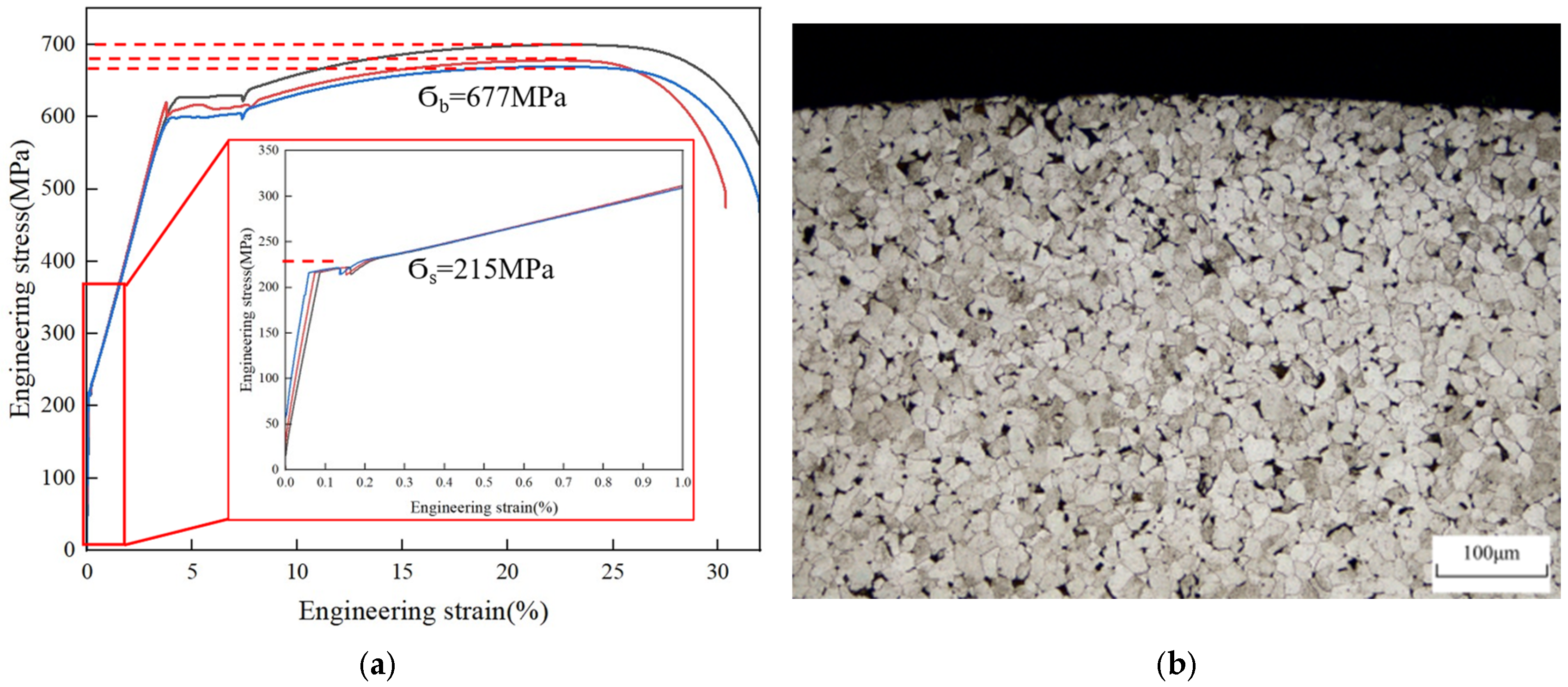
The degree of plastic deformation in the spinning forming process is intense. Usually, good plasticity is chosen as the spinning blank, and the material’s strength properties need to be considered for the multi-ribbed pulley. Therefore, the original material used in this experiment is the annealed SPHE hot rolled soft steel, processed into the round bar specimen shown in Figure 1 for the spinning experiments. SPHE steel, as an ordinary low-carbon steel, has good flexibility and plasticity [22]. The results of the tensile mechanical property measurements are shown in Figure 2a, and the results are averaged to find the yield strength of 215 MPa, the tensile strength of 677 MPa, the yield-to-strength ratio of 0.31 MPa, and the strength ratio of 0.31 MPa. The tensile strength of 677 MPa, the yield-to-strength ratio of 0.317, elongation at break of 45%, and the material composition is shown in Table 1. The untreated specimens exhibited an annealed organisation of predominantly white ferrite and black pearlite, with uniformly distributed grains, as shown in Figure 2b, with an average grain size of 34 μm for white ferrite.

2.2. Ultrasonic-Assisted Spinning Device Working Principle and Force Analysis

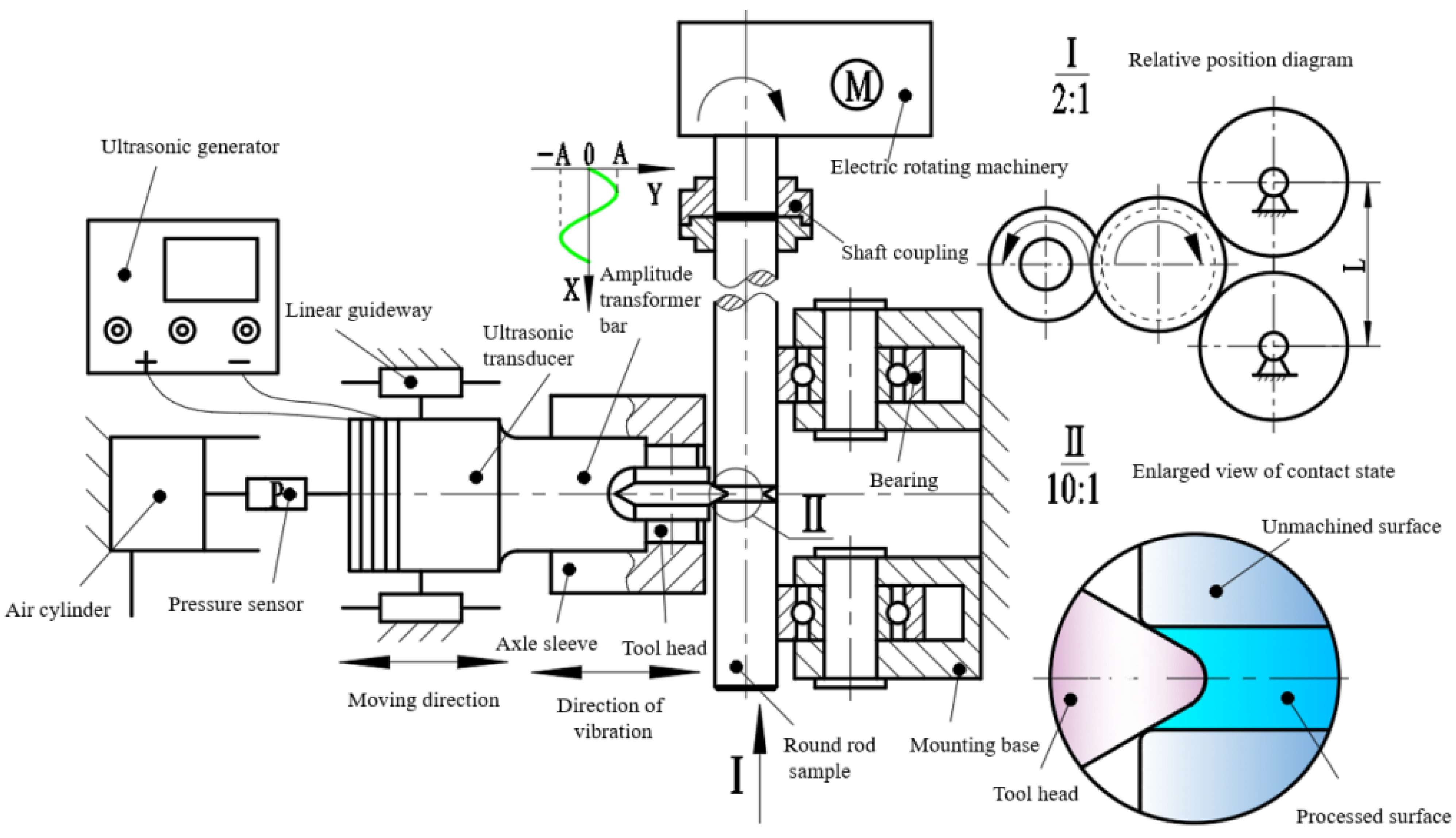
The spinning experiments were carried out using an ultrasound-assisted spinning device (HK20F/Kt, Shandong Huayun Electromechanical Technology Co., Ltd., Jinan, China), which is shown in the schematic diagram of the device in Figure 3. The SPHE steel round bar specimen was clamped on the coupling, the motor drove the specimen to rotate, and the cylinder exerted the pressure on the transducer module, which was moved through the linear slider to make the tool head contact the specimen. During the forming process, the transducer converts high-frequency electrical signals from the ultrasonic generator into ultrasonic vibrations. These vibrations are amplified by an amplitude lever and transmitted to the tool head, creating a dynamic load. This dynamic load, combined with the static load applied by the tool head, forms the total forming load used for processing the V-groove structure of the spinning pulley.
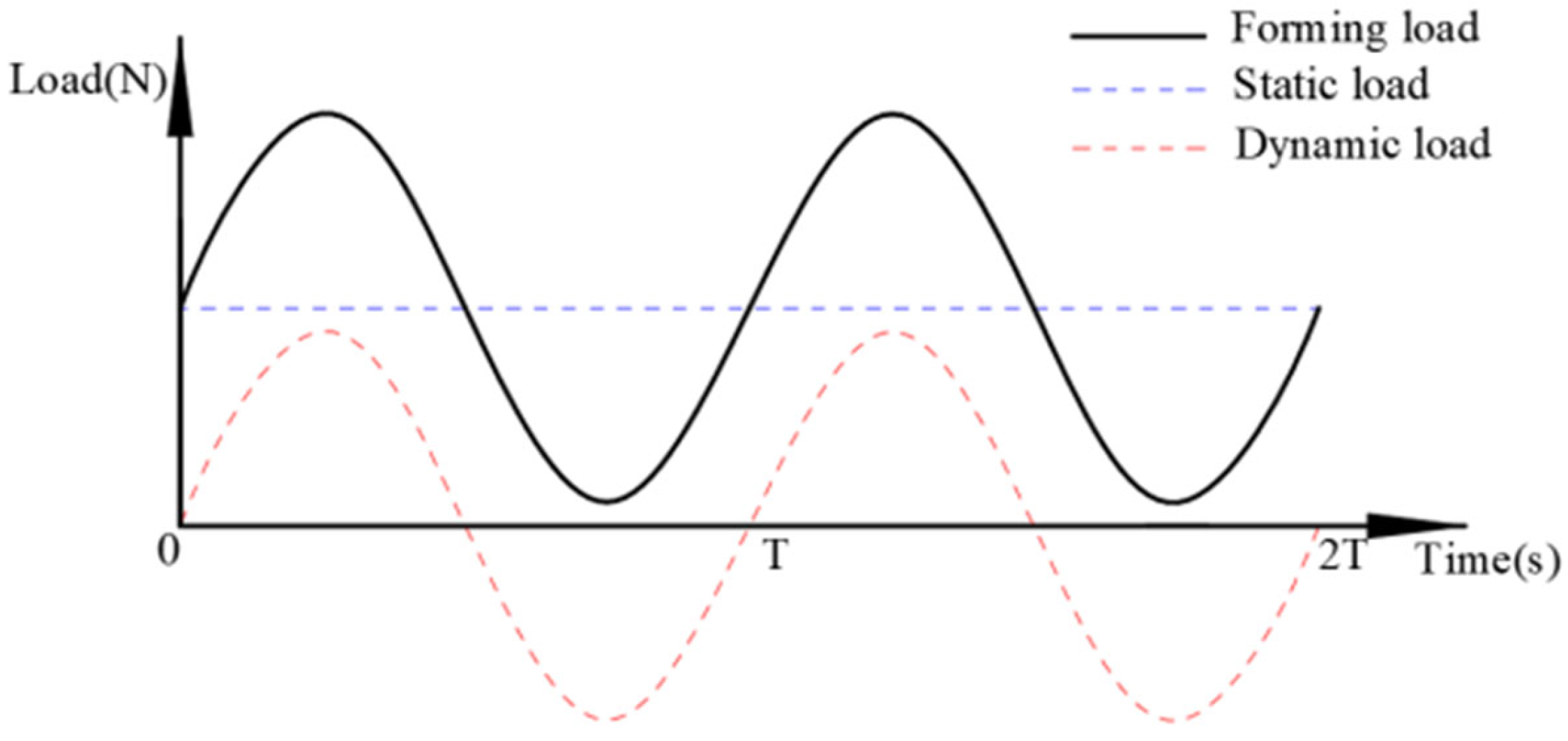
The force state in the ultrasonic-assisted spinning process is analysed as shown in Figure 4. In the ultrasonic-assisted spinning process, the specimen is simultaneously subjected to the static preload applied by the tool head and the cyclic ultrasonic dynamic load; the displacement equation is y = A0sin(2πft) [23], where y is the displacement of the ultrasonic vibration; A0 is the amplitude (μm); and t is the time (s). The ultrasonic vibration of the tool head is a sinusoidal signal. The velocity equation is v = 2πfA0cos(2πft); the total force exerted by the tool head can be calculated by Equation (1), where F is the forming load; Fs is the static load; and Fd is the dynamic load of the tool head.
F = F s + F d
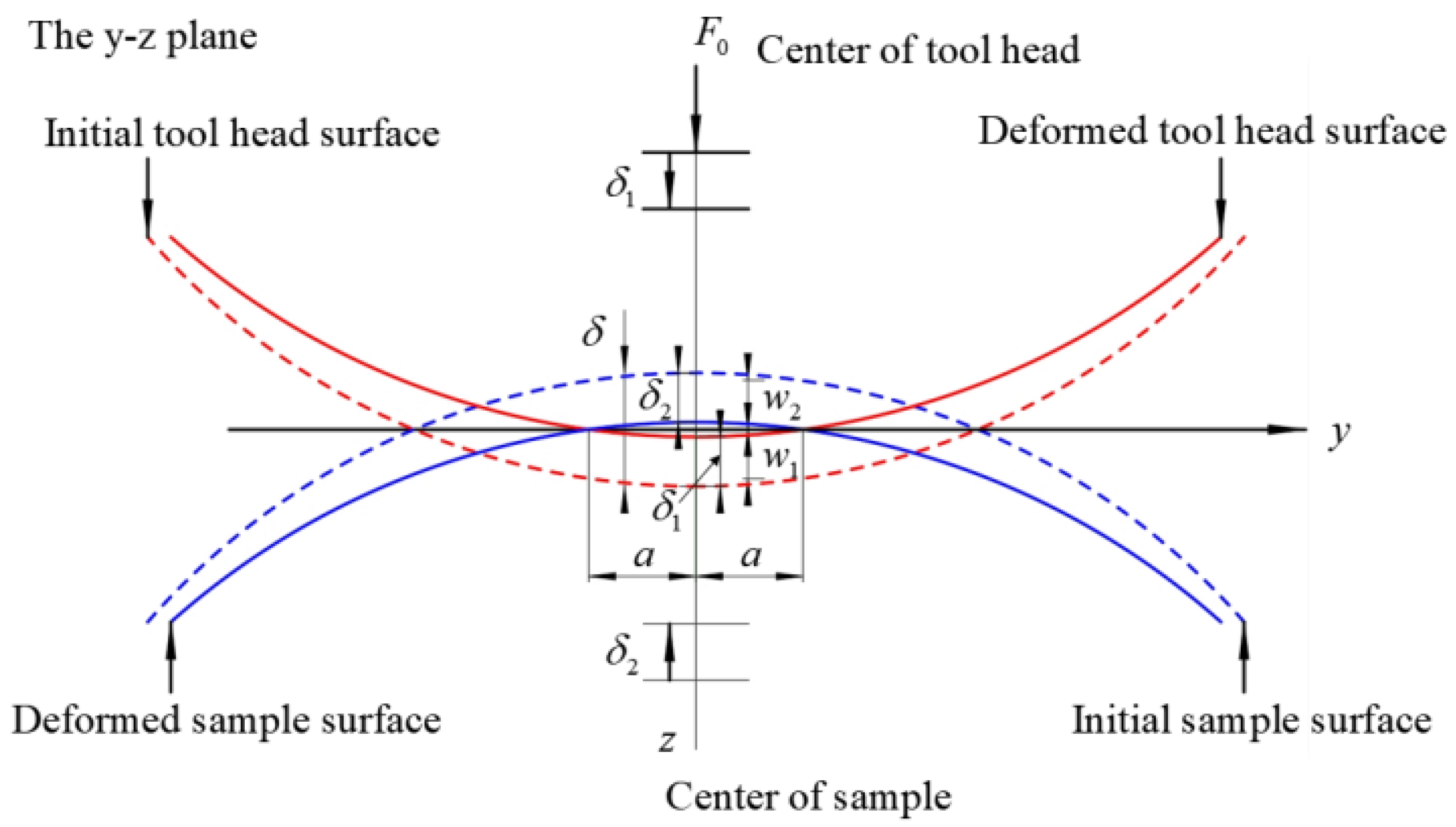
In this paper, the force relationship between the tool head and the specimen is calculated by the Hertzian contact model, considering the following assumptions: (Ⅰ) the surfaces of the tool head and the specimen are continuous; (Ⅱ) there is no friction on the contact surfaces between the tool head and the specimen; (Ⅲ) the part can be considered as an elastic half-space; (Ⅳ) the strains are minor, and the deformations of the material are symmetrical; and (Ⅴ) the plasticity and elasticity of the material are both isotropic [24]. Based on the Hertz contact theory and from the geometric conditions of Figure 5, the maximum displacement average to the centre point of contact between the tool head and the centre of the specimen can be obtained δmax; the relationship between P0 and δ can be obtained from Equation (3).
δ max = 2 P 0 π l 0 ( 1 μ 1 2 E 1 + 1 μ 2 2 E 2 )
P 0 = π δ l 0 2 ( 1 μ 1 2 E 1 + 1 μ 2 2 E 2 )
where P0 is the force applied to the tool head, l0 is the elastic contact radius between the tool head and the specimen, and E1, E2, μ1, and μ2 are the Young’s modulus and Poisson’s ratio of the tool head and the specimen, respectively.
According to the law of conservation of energy, most of the initial kinetic energy of the tool head is converted into the elastic potential energy of the specimen. A small portion of the kinetic energy is lost in the process of impacting [23]. In Equation (5), k is the efficiency coefficient related to elastic and thermal dissipation during ultrasonic impact, and in this paper, k is taken as 0.85 [25]. m is the mass of the tool head, which can be solved for the maximum displacement δmax, which is normal for the contact centre point when the impact velocity takes the maximum value of vmax = 2πfA0 Equation (5).
k 1 2 mv max 2 = 0 δ max P 0 d δ = 0 δ max π δ l 0 2 ( 1 μ 1 2 E 1 + 1 μ 2 2 E 2 ) d δ
δ max = 2 k m v max 2 ( 1 μ 2 2 E 1 + 1 μ 2 2 E 2 )
Similarly, bringing Equation (6) into Equation (4) yields the magnitude of P0, and hence the dynamic load Fd can be expressed as
F d = P 0 sin ( 2 π f t )
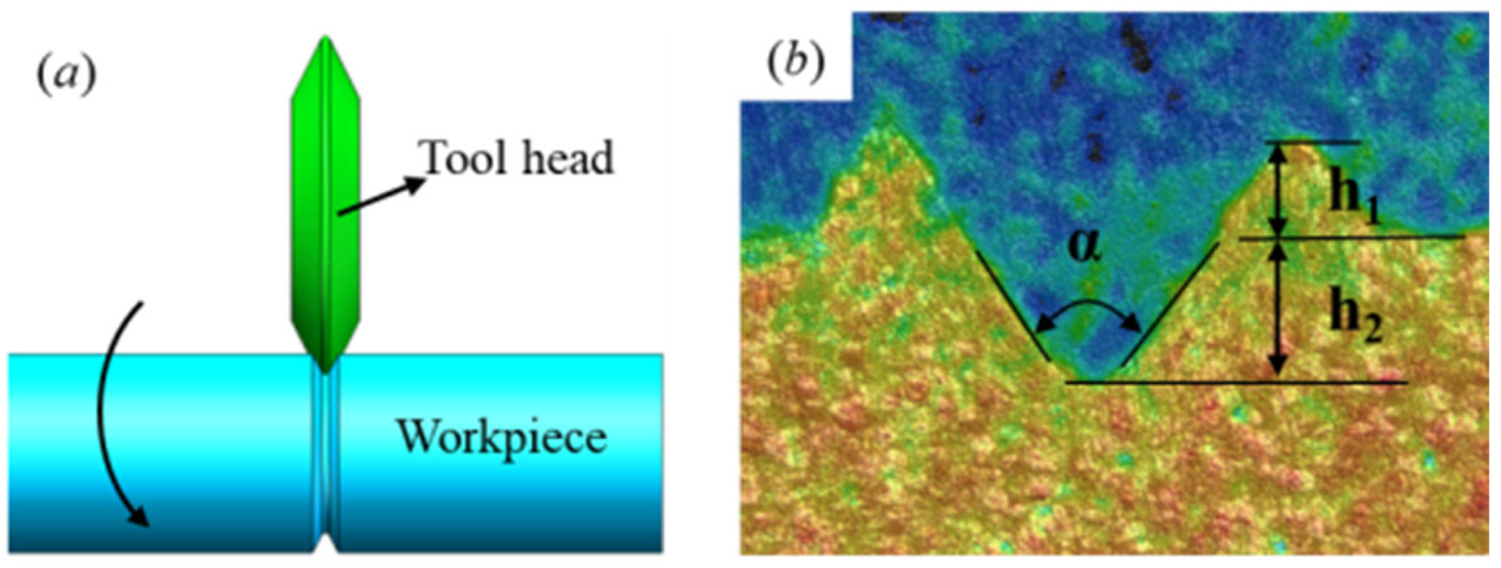
Figure 6a,b are schematic diagrams of the specimen after deformation and V-groove dimensions, respectively. The mating dimensions in the pulley are mainly based on the angle and tooth depth, so this paper characterises the ultrasound-assisted spinning accuracy in terms of the depth of the groove after forming, h2, and the inclination angle α, h1 as an evaluation of the material mobility index.
In Figure 6a, the green component is the tool head and the blue component is the workpiece after spinning. The rotation of the workpiece drives the tool head to rotate. In Figure 6b, the precision of ultrasonically assisted spinning is characterised by the post-forming groove depth h2, the inclination angle α, and the groove height h1 as an indicator of material mobility.

2.3. Ultrasonic-Assisted Spinning Experiment Programme

A one-way experiment was designed to investigate the effect of ultrasonic assistance on the V-groove forming quality of round bar specimens processed with different spinning static loads; the parameters of the experimental programme are shown in Table 2. The spinning experiments (Group A) with static loads of 200–700 N, ultrasonically assisted spinning (Group B) with ultrasonic vibration of amplitude of 12 μm, frequency of 20 kHz superimposed based on Group A, which is defined as the static load + UAS, were carried out on the setup shown in Figure 7, which shows the setup on which the experiment was carried out.
In this study, the experimental specimens were cut by molybdenum wire ionised EDM, and the surfaces were ground and polished to a mirror finish with metallographic sandpaper (200# to 2000#). Subsequently, the specimens treated with different processes were corrupted with a 4% nitric acid alcohol solution, and the corrosion time was varied according to the other modification processes until the surface of the specimens changed from metallic lustre to greyish. The specimens were subjected to tissue observation, comparative analysis of the size of the grains after treatment according to different process parameters, and measurement of the height of the material flow h1, the depth of the V-groove h2, and the forming inclination angle α after forming were carried out to characterise the forming accuracy. A laser confocal microscope (VK-X1000K, Keyence, Osaka, Japan) was used to measure the surface morphology of the groove bottom area of the specimens. The hardness of the groove bottom in the cross-section of the specimens before and after ultrasound-assisted spinning treatment was measured using a Vickers microhardness tester (FALCON-500, INNOVATEST, Maastricht, The Netherlands, Europe), with a loading force of 100 g and a holding time of 10 s. Five randomly selected sampling points near the groove bottom with more than 50 μm spacing were used to measure and calculate the average microhardness. Surface circumferential residual stresses (Cr target, 20 kV, 5 mA) were measured using an X-ray diffractometer (HDS-I, Hydrostar, Xiamen, China).

2.4. Simulation Modelling Pre-Processing

Finite elements were performed on the V-groove of the multi-ribbed pulley, with the tool head material, cemented carbide (WC), having a hardness of about 2528 HV0.1, and the specimen, SPHE steel, having a hardness of 180 HV0.1. The stiffness of the tool head was much greater than the specimen to be processed; therefore, the tool head was defined as a discrete rigid body and the specimen as a 3D deformable entity [25].
The model assembly is shown in Figure 8, and the simulation uses explicit kinetic analysis to simulate the plastic deformation and residual stress field of the ultrasound-assisted spinning of the SPHE steel round bar specimen. In the boundary load module of ABAQUS, the cycle amplitude interface is created as shown in Figure 8b, with the frequency ω = 2πf = 2 × 3.14 × 20,000 rad/s = 125,600 rad/s. In the interaction module, RP and RP1 are selected, and line features are created. Next, create the connection section, select basic information for connection type, select axial for translation type, check the created line features, create the connection assignment, and leave the rest of the settings as default. Finally, in the load module, create boundary conditions, select the connection displacement, set the amplitude of 12 μm, and obtain the sinusoidal curve shown in Figure 8c. Then apply the contact action region as well as the boundary load conditions [26,27] to the tool head and the workpiece and calculate the stress–strain distribution of the workpiece V-groove.

3. Results and Analysis

3.1. Analysis of Forming Accuracy Results of Ultrasound-Assisted Spinning Experiment

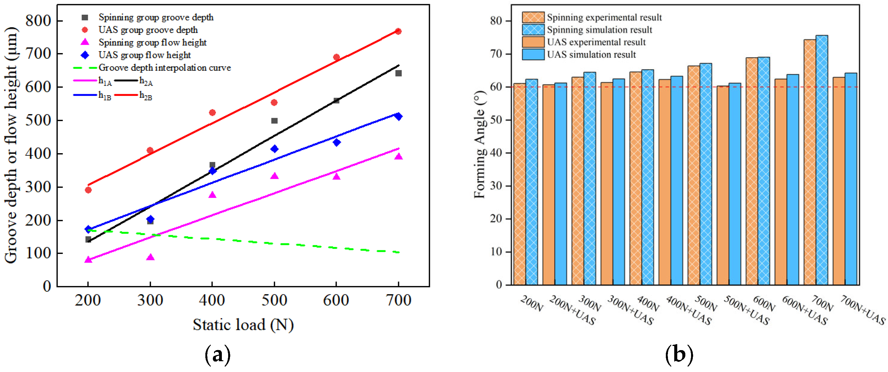
The three-dimensional morphology with groove depth and angle measurement data after spin forming is shown in Figure 9. In the spinning group, the V-groove depth is 142.62 μm when the static load is 200 N (Figure 9a). The groove depth is increased to 642.75 μm when the static load is 700 N (Figure 9k), but the rate of increase in the groove depth is relatively slow. After the addition of ultrasonic assistance, the V-groove depth is further deepened based on spinning forming, and when the static load is 200 N, the depth of V-groove is 290.72 μm (Figure 9b), and when the static load is 700 N, the depth of groove is increased to 768.53 μm (Figure 9l), which is a significant improvement of the depth of the V-groove under the same static load. After spin forming the material flow height h1, the change rule is similar to the change rule of depth, which is shown when the static load is 200 N and the flow height is 80.90 μm (Figure 9a). When the static load is 700 N, the flow height is increased to 390.92 μm (Figure 9k), but the flow height is increased slowly; after adding ultrasonic assistance, the material flow height is more prominent, and the flow of the material on both sides of the groove is more noticeable when forming under the same static load. The flow height is increased to 122.04 μm and it reaches 512.96 μm (Figure 9l).
The tool head angle is 60°; due to the moulding process of the tool head’s first contact with the workpiece, at this time, there is specific static load on the workpiece. The workpiece drives the tool head to rotate, and the spinning moulding angle will increase. Experiments have shown that as the static load increases, the moulding angle increases; when the static load is 200 N, the moulding angle is 61.05°, and the angle of the head of the tool is close to the angle of the tool head. Still, when the forming load is increased to 700 N, the forming angle is 74.32°, which is a large amount of angular change and seriously affects the forming accuracy; when ultrasonics is added, when the static load is 200 N, the forming angle is 60.68°, and when the static load is 700 N, the forming angle is only 62.96°, and the forming angle is more consistent.
In the spinning group, with the increase in static load, the depth of the groove obtained shows an increasing trend; after adding ultrasonic assistance, the groove forming depth increases significantly under the same static load, which is consistent with the theoretical analysis of the effect of ultrasonics. Moreover, in the spinning group, with the increase in static load, the angular deviation of groove moulding becomes bigger gradually, and the angular deviation is 23.87% when the static load is 700 N. After adding ultrasonic assistance, the groove forming angle is closer to the tool head angle, and the inclination angle of the groove is smaller than the 60-degree taper angle of the tool head with a deviation of only 4.9%, which improves the accuracy significantly after ultrasonics. A paired sample t-test (Figure 9) was conducted to compare the groove depth under different static force values. The data from the experimental group was significantly higher than that of the control group (t(5) = 6.62, p < 0.001), with a mean difference of 139.46 (95% CI [85.29, 193.63]). This indicates a significant effect of the experimental treatment condition.

3.2. Metallographic Microstructure Analysis (OM Microstructure Analysis)

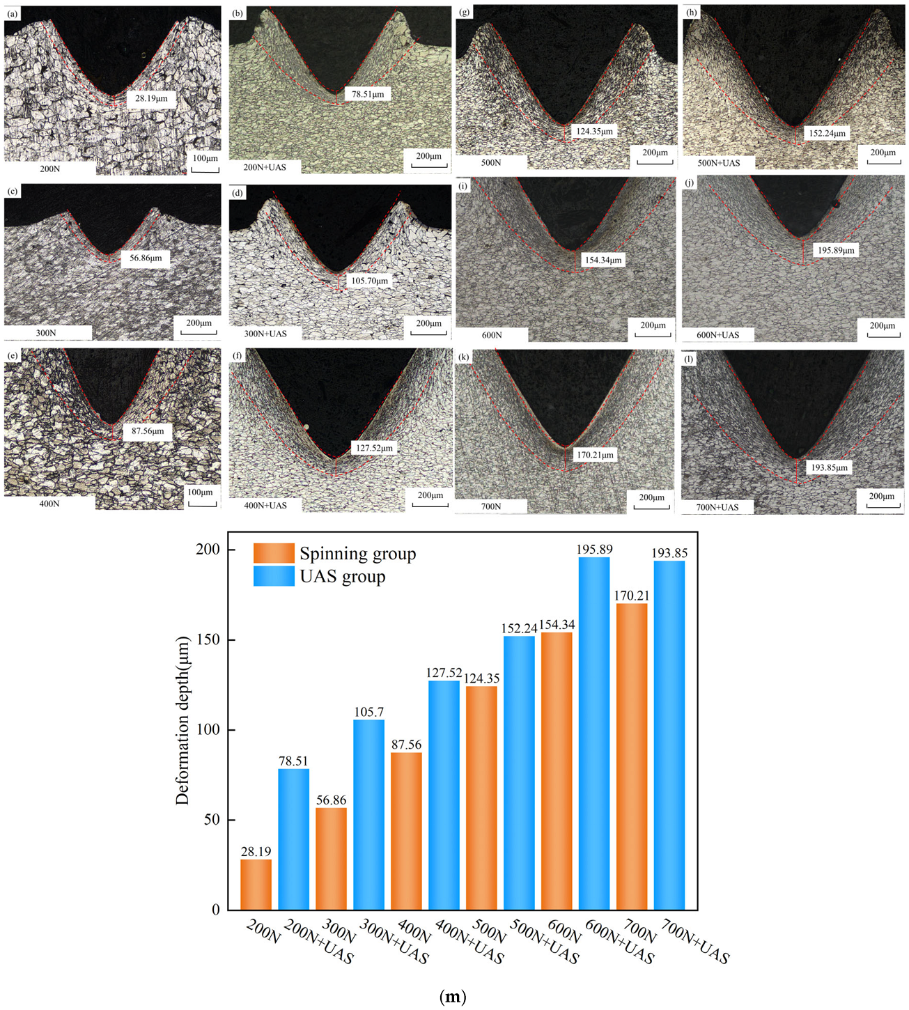
After spin forming, the grains showed streamlined flattened particle distribution in the subsurface layer along the bottom contour of the V-groove, and the depth of the deformation-influenced layer increased with the increase in the static load, as shown in Figure 10. In the spinning group, when the static load is 200 N, the depth of the deformation-affected layer is 28.19 μm (Figure 10a), and when the static load is to 700 N, the depth of the affected layer reaches 170.21 μm (Figure 10k); contrastingly, in ultrasound-assisted spinning, when the static load is 200 N, the depth of the deformation-affected layer is 78.51 μm (Figure 10b), and when the static load is 700 N, the depth of the deformation-affected layer reaches 193.85 μm (Figure 10l). Spinning can provide a certain depth of a hardened layer on the surface of the workpiece, but subsequently, with the increase in the depth, the static load keeps increasing with geometrical multiples, while the introduction of ultrasound-assisted spinning significantly improves the depth of the deformation-affected layer. As seen from Figure 10m, the depth of the grain deformation impact layer increases with the increase in static load. At the same time, the surface hardness and its trend are similarly positively correlated with the change in static load, the high-frequency vibration of the tool head and compression deformation in the forming process can continue to hit the surface of the metal material, increasing the static load of the UAS group, the tool head under the action of the impact force will be more energy transfer to the bottom of the V-groove metal surface, making the grain refined, resulting in a continuous slip of grain boundaries to harden the impacted area, thus improving the surface hardness. Under the impact force, the tool head will transfer more energy to the metal surface at the bottom of the V-groove, making the grain refined, and the grain boundaries slip, resulting in the hardening of the impacted area, thus improving the hardness of the surface layer. The data (Figure 10) from the experimental group was significantly higher than that of the control group (t(5) = 8.72, p < 0.001), with a mean difference of 38.70 (95% CI [27.29, 50.11]). This indicates a significant effect of the experimental treatment condition.

3.3. Analysis of Microhardness Results

The results of the surface hardness measurements on the bottom of the V-groove are shown in Figure 11. The surface hardness of the untreated specimen is 178.27 HV0.1. After adding the ultrasonic aid, the surface hardness of the bottom of the specimen groove is increased to 235.81 HV0.1, which is 32% higher than that of the untreated specimen. The high-frequency vibration of the tool head and compression deformation during the ultrasonic impact process leads to the hardening of the surface layer of the specimen to a greater degree. The impact force causes the grain fragmentation to become finer and more uniform, and the depth of the hardened layer is 78~194 μm. It was also observed that in the spinning group, the surface hardness of the specimen groove bottom tended to increase, decrease, and then increase with the increase in static load. Still, all of them were higher than the hardness of the untreated specimens. It was determined that spinning could introduce compressive deformation perpendicular to the material surface and tensile deformation parallel to the material surface to the bottom of the specimen grooves, resulting in work hardening on the surface. For the UAS group, it was observed that with the increase in static load, the surface hardness of the bottom of the specimen groove shows an increasing trend. By increasing the static load of the UAS group, the tool head will transfer more energy to the metal surface at the bottom of the V-groove, which produces intense plastic deformation to obtain a more profound deformation of the area of influence, which in turn aggravates the surface hardening of its surface, and thus improves the surface hardness [28,29,30].

3.4. Measurement and Analysis of Surface Roughness of Groove Bottom

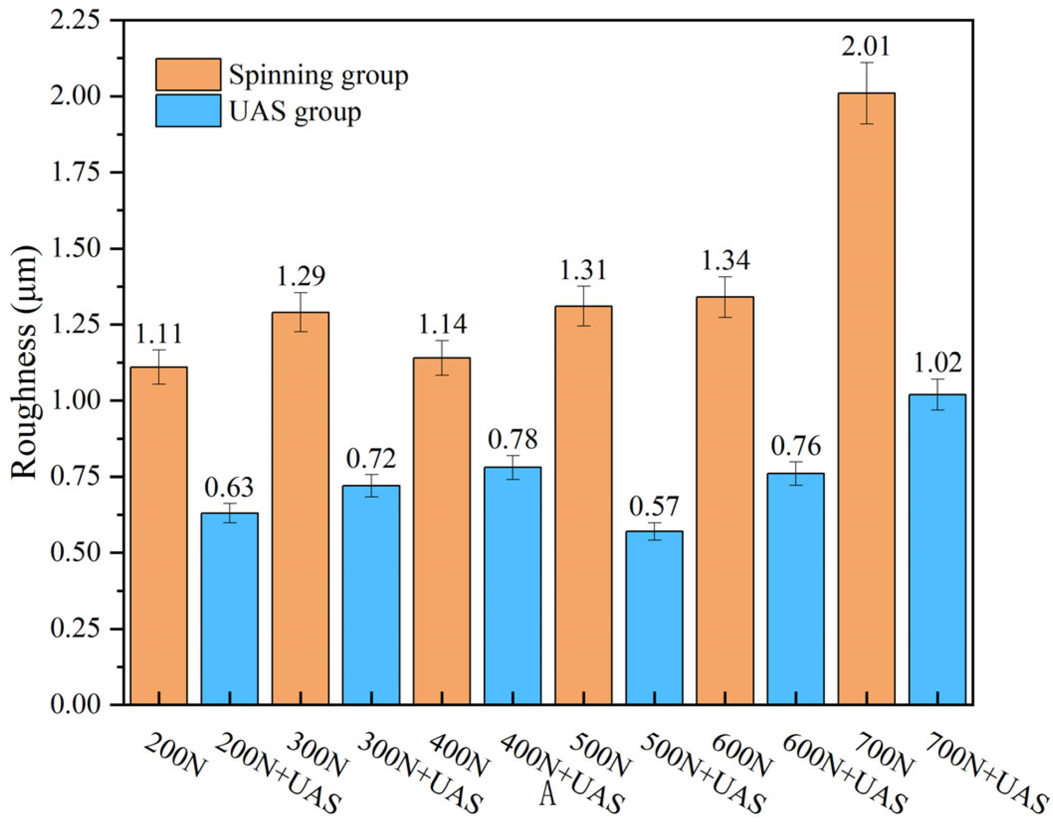
According to the data in Figure 12, the surface roughness of the groove bottom in the spinning group shows an overall increasing trend with the increase in static load, and when it reaches 700 N, the material undergoes substantial plastic deformation and the surface roughness increases sharply. In the ultrasonic-assisted group, the surface roughness of the groove bottom showed an increase followed by a decrease and then an increase with the rise in static load. Compared with the specimen’s original surface roughness of 3.2 μm, the variation in static load in a particular range can reduce the surface roughness of the groove bottom to a certain extent. Comparative analysis showed that ultrasound-assisted spinning could significantly improve the surface roughness of the groove bottom [11], and when the static load was 500 N, the minimum surface roughness of 0.57 μm was obtained, and the surface roughness after a maximum of 51.16% reduced ultrasound-assisted treatment compared with that of the spinning group. Continuing to increase the static load improves the roughness. If weakened, with too much increase in static load, it will cause the surface to be subjected to more ultrasonic impacts from the tool head, resulting in the generation of tiny cracks and debris. As the surface roughness began to become more prominent, the surface properties appeared to be degraded, so the ultrasonic spinning system is required to provide greater power and the stability of the system operation is affected at high loads, resulting in uneven changes in the vibration state of the tool head. This in turn affects the plastic deformation of the groove bottom surface, which affects the quality of the groove bottom surface [31].

3.5. Residual Stresses

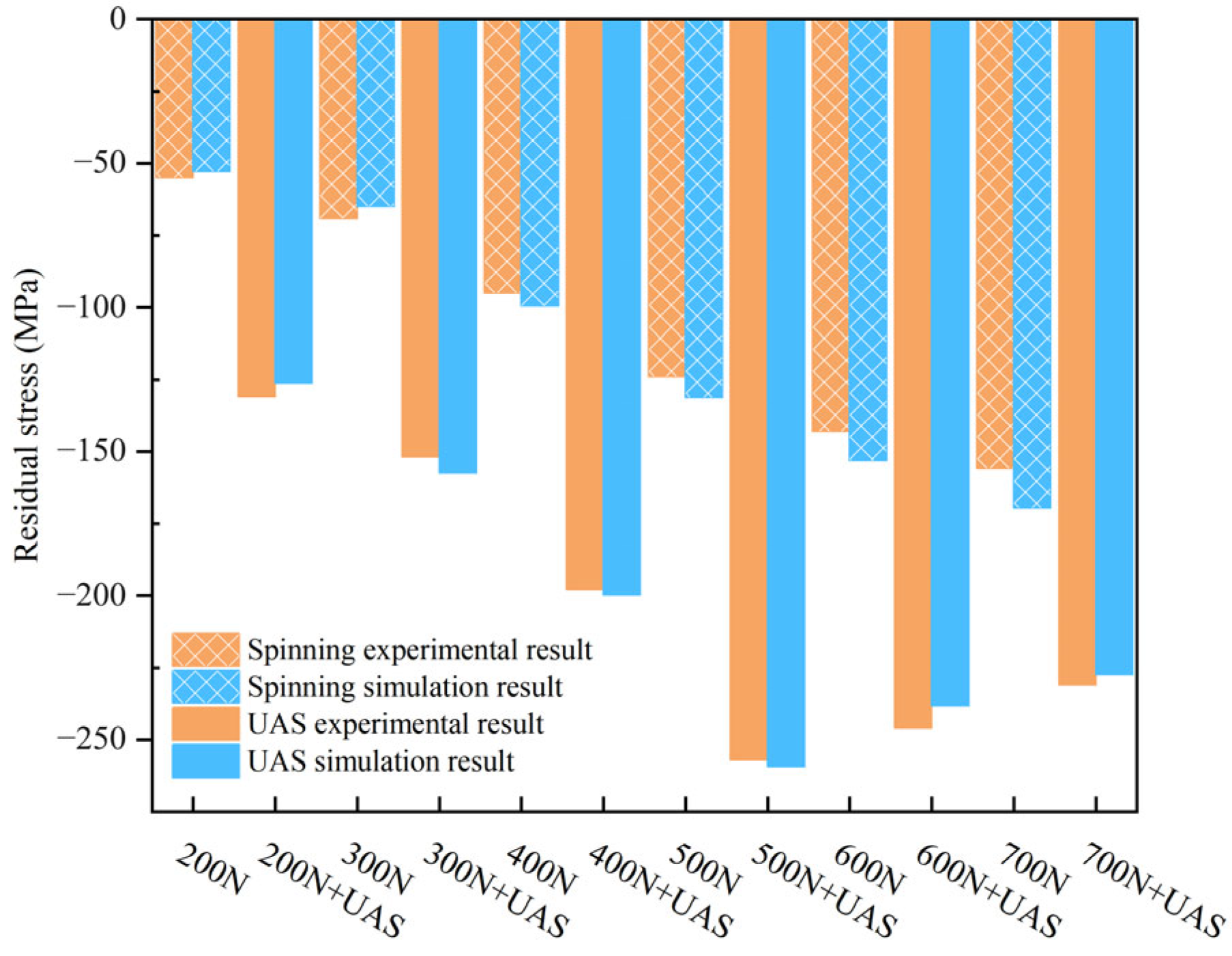
The residual stress at the bottom of the groove was measured for the untreated specimens, the specimens in the spinning group and the ultrasound-assisted group; the residual compressive stress on the surface of the untreated specimens was 11 MPa. The results of the residual stress on the surface of the spinning moulding are shown in Figure 13, and in the spinning group, the residual compressive stress was 55 MPa when the static load was 200 N, and the residual compressive stress was 231 MPa when the static load was 700 N. The residual compressive stress increases with static load, but it increases slightly. However, after ultrasound-assisted spinning, a higher residual compressive stress was introduced on the surface of the specimen [32], and the residual compressive stress showed a tendency of increasing and then decreasing with the increase in the static load: when the static load was too small, the yield area of the surface of the material was small; when the static load was increased, a large area of the surface of the material yielded, and at this time, the magnitude of the residual stress would have a substantial increase; when the static load continued to be increased, the surface of the material would produce more significant deformation and the residual stress value would continue to increase, but the plastic strain had taken over the dominant position, so the residual stress growth will not produce a substantial increase in the size of the residual stress. A static load of 500 N on the specimen surface is needed to obtain the maximum residual compressive stress of 257 MPa. Continue to increase the static load; the residual stress value will decline; too high of a static load will make the local area of the contact stress larger and more significant to exceed the strength limit of the specimen surface material, resulting in the generation of surface cracks, thus releasing part of the residual compressive stress.

4. Discussion

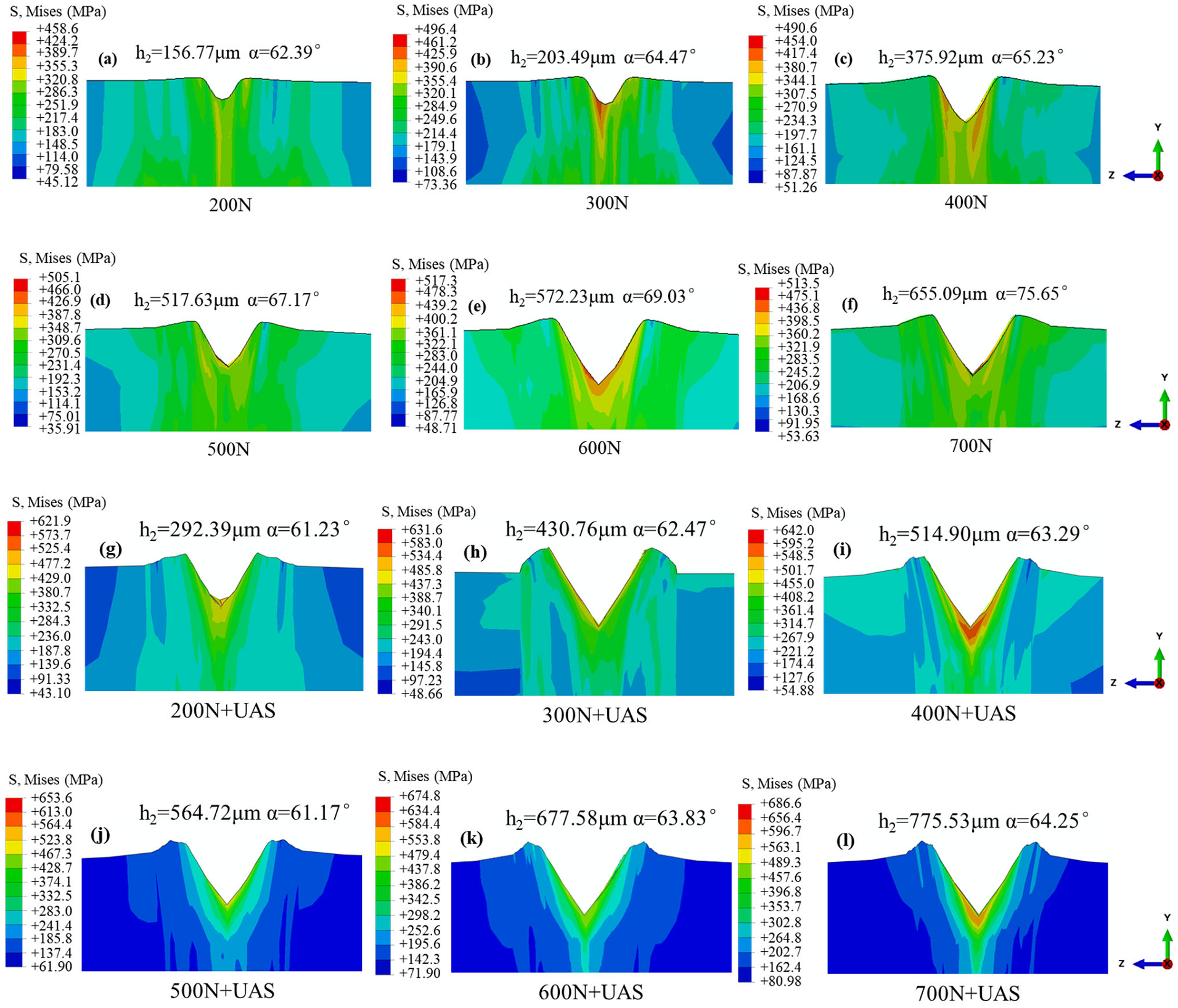
The finite element forming accuracy results are shown in Figure 14. In the spinning group, when the static load is 200 N, the depth of the V-shaped groove is 156.77 μm (Figure 14a), when the static load is 700 N, the groove depth is increased to 655.09 μm (Figure 14f), but the rate of increase in the depth of the groove is relatively slow. After adding ultrasonic assistance, when the static load is 200 N, the depth of the V-shaped groove is 292.39 μm (Figure 14g), when the static load is 700 N, the depth of the groove is increased to 775.53 μm (Figure 14l), the depth of the V-shaped groove under the same static load is significantly improved, and with the increase in the static load, the rate of increase in the depth of the groove in the UAS group is faster, which is in agreement with the rule of change in the experimental measurements. When the static load is more significant than 400 N, due to the refinement of the local mesh, cell mesh distortion is gradually more significant as the static load is increased, and the rounded corner radius at the bottom of the groove may not be completely accurate within the limited computational resources. The degree of the notch bottom fillet radius is minimal, and it may not be possible to achieve precise mesh resolution in the limited computational resources and time, so the fillet at the bottom of the notch will show sharp geometric features. The labels a to f represent the static load experimental groups, with Figure 14a corresponding to 200 N, Figure 14b to 300 N, and so on up to Figure 14f. The labels Figure 14g–l represent the ultrasonically assisted spinning (UAS) experimental groups, with g corresponding to 200 N + UAS, Figure 14h to 300 N + UAS, and so on up to Figure 14l.
The data of flow height h1 and notch depth h2 are shown in Figure 15a, in which the relationship of the fitted curves calculated by fitting for the spinning group and ultrasound-assisted spinning group are as follows: h1A = −50.5494 + 0.6668F1, h1B = 33.2875 + 0.7008F2, h2A = −76.76629 + 1.0632F1, h2B = 121.02276 + 0.93025F2 (where F1 and F2 are the static loads, N, for groups A and B; h11 and h12 are the flow heights for groups A and B, respectively, and h21 and h22 are the depths of the grooves in groups A and B, respectively, μm). The regression correlation coefficients are R1A = 0.9372, R1B = 0.9760, R2A = 0.9876, R2B = 0.9917, indicating a strong correlation. The maximum flow height of 122.04 μm occurs when the static load is 700 N. The overall error between the notch depth simulation results and the experimental results is within 10%, which verifies the accuracy of the present model. The notch depth becomes more profound with the increase in static load, showing a linear increasing trend. However, the dominant role of static load and ultrasound among the dominant factors in the change in notch depth varies within a specific range, and with the increase in static load, the role of ultrasound assistance gradually becomes smaller; the deeper the depth of the formed notch, the larger the contact area becomes, and more ultrasound energy needs to be provided. The UAS group requires less static load to create the same groove depth. In contrast, the dynamic and static loads form the total forming load (corresponding to the enormous static load in group A). Still, the role of ultrasound decreases with the depth of the forming groove, and the ultrasound system needs to provide more energy to form greater depths. As illustrated in Figure 15b, which shows the angle measurement results at the bottom of the V-shaped groove, the tool head has an initial angle of 60°. During the moulding process, the tool head initially contacts the workpiece under a certain static load. The workpiece then drives the tool head to rotate, causing the forming angle to increase. Experimental observations revealed that as the static load increases, the forming angle also continuously increases.
By extracting the residual stress values in the grid cells and comparing them with the experimental results, the curves shown in Figure 16 can be obtained, which are closer to the trend of the experimental measurements; the overall error between the simulation results and the experimental results is within 8%, which verifies the accuracy of the present model. It can be observed that after the UAS treatment, the material surface plastic deformation residual compressive stress has a significant increase based on the rise in static load. Perpendicular to the specimen surface layer of the compression deformation region and parallel to the surface layer of the tensile deformation region, extremely small interlacing will occur, showing the grains in the shear stress under the action of the relative sliding displacement along the specific grain surface and grain direction [33], so that the surface layer of the residual stress of the material shifts from tensile stress to compressive stress. The residual stress in the surface material is transformed into compressive stress. But with static load that is too high, the residual compressive stress increase will not produce a substantial increase because the local area contact stress continues to become more prominent to have exceeded the specimen surface material strength limit, resulting in the generation of small cracks, so that the residual compressive stress is partially released. After ultrasound-assisted treatment, intense plastic deformation of the surface layer of the material and internal grain distortion are caused. Then the grains are broken, dislocated, slipped, and obliterated, and the grain refinement constantly expands. A hardened layer is formed on the material’s surface so that the material’s surface hardness and strength are increased.

5. Conclusions

In this paper, mechanical modelling, finite element simulation, and experimental verification methods are used to study the V-groove forming process of the ultrasonic-assisted spinning process of SPHE steel round bar specimens. Moreover, the influence of ultrasonic-assisted spinning on the quality of spinning with different static loads is investigated by measuring the depth and inclination of the V-groove, microhardness, organisational structure, and surface roughness. The main conclusions are as follows:
(1) The ultrasonic-assisted process utilises the acoustic softening effect induced by high-frequency vibrations to significantly reduce the flow stress of the material, thereby enhancing its plastic deformation capability during spinning. This change in material behaviour allows the depth of the V-groove to increase substantially from 197.64 μm to 410.35 μm, effectively improving material filling performance and forming accuracy. Meanwhile, under a static load of 700 N, ultrasonic assistance reduces the V-groove angle from 74.32° to 62.96°, indicating that ultrasonic vibration improves the material’s stress adaptability and deformation compatibility, suppresses springback, and promotes more consistent angular distribution.
(2) Ultrasonic vibration promotes grain refinement and the formation of a plastic deformation layer on the surface, significantly enhancing the surface integrity of the workpiece. Under a static load of 500 N, the surface roughness is reduced by up to 51.16%, demonstrating the optimising effect of ultrasonic vibration on surface plastic flow. Under a load of 700 N, ultrasonic assistance refines the grain size by up to 42.62% and induces a notable work-hardening effect, increasing the surface microhardness by up to 32%. This indicates that ultrasonic treatment not only alters surface morphology but also significantly influences the material’s microstructure and mechanical properties.
(3) Ultrasonic vibration introduces dynamic contact stresses in localised areas, effectively counteracting the tensile stress state on the specimen surface and inducing plastic deformation at greater depths. As a result, a residual compressive stress layer of up to 257 MPa is formed in the material surface layer. The presence of this compressive stress field helps improve the fatigue performance and stress corrosion resistance of the component. Simulation and experimental results show consistent trends in changes, with forming accuracy errors of less than 10%, indicating that the ultrasonic-assisted spinning process offers good predictability and controllability in both macroscopic forming and microscopic material behaviour.

Author Contributions

Conceptualization, S.C. and Z.X.; Methodology, S.C., W.W., Q.J. and Z.Z.; Software, W.W. and Y.L. (Yongqing Lai); Validation, Q.J.; Formal analysis, W.W., J.G. and Y.L. (Yuhong Liu); Investigation, Q.J., J.G., Y.L. (Yongqing Lai) and Y.L. (Yuhong Liu); Resources, Z.X.; Data curation, Y.L. (Yuhong Liu); Writing—original draft, S.C., W.W., J.G. and Z.Z.; Writing—review & editing, S.C.; Visualization, Y.L. (Yongqing Lai); Supervision, Z.X. and Z.Z.; Project administration, Z.X.; Funding acquisition, Z.X. All authors have read and agreed to the published version of the manuscript.

Funding

The work described in this paper was supported by the Science and Technology Projects of Fujian Province 2022HZ024009; Finance Department Science and Technology Project of Fujian Province B2023346; Science and Technology Plan Leading Project of Fujian Province 2022H0020; Xiamen Municipal Bureau of Science and Technology 3502Z20231001; Xiamen Municipal Bureau of Science and Technology 2023CXY0314.

Data Availability Statement

All data generated or analysed during this study are included in this published article.

Conflicts of Interest

The authors declare that they have no known competing financial interests or personal relationships that could have appeared to influence the work reported in this paper.

References

  1. Music, O.; Allwood, J.M.; Kawai, K. A Review of the Mechanics of Metal Spinning. J. Mater. Process. Technol. 2010, 210, 3–23. [Google Scholar] [CrossRef]
  2. Xia, Q.; Xiao, G.; Long, H.; Cheng, X.; Sheng, X. A Review of Process Advancement of Novel Metal Spinning. Int. J. Mach. Tools Manuf. 2014, 85, 100–121. [Google Scholar] [CrossRef]
  3. Zhang, S.G. Research on Deformation Stability in Spinning and Molding of Pulley Hub. Ph.D. Thesis, Hefei University of Technology, Hefei, China, 2014. [Google Scholar]
  4. Pan, Y.; Xue, G.L.; Zhe, C.; Yang, Y. Roller Spinning Forming Regularity. J. Meas. Eng. 2017, 5, 229–234. [Google Scholar] [CrossRef]
  5. Ahmed, K.I.; Gadala, M.S.; El-Sebaie, M.G. Deep Spinning of Sheet Metals. Int. J. Mach. Tools Manuf. 2015, 97, 72–85. [Google Scholar] [CrossRef]
  6. Xue, K.; Zhou, J.; Yan, S.; Li, P. Flow Diversion Mechanisms and Control Methodology in the Asymmetric Spinning of Special-Shaped Multi-Wedge Belt Pulley. Int. J. Adv. Manuf. Technol. 2022, 120, 5289–5302. [Google Scholar] [CrossRef]
  7. Razani, N.A.; Jalali Aghchai, A.; Mollaei Dariani, B. Flow-Forming Optimisation Based on Hardness of Flow-Formed AISI321 Tube Using Response Surface Method. Int. J. Adv. Manuf. Technol. 2014, 70, 1463–1471. [Google Scholar] [CrossRef]
  8. Molladavoudi, H.R.; Djavanroodi, F. Experimental Study of Thickness Reduction Effects on Mechanical Properties and Spinning Accuracy of Aluminium 7075-O during Flow Forming. Int. J. Adv. Manuf. Technol. 2011, 52, 949–957. [Google Scholar] [CrossRef]
  9. Debin, S.; Guoping, Y.; Wenchen, X. Deformation History and the Resultant Microstructure and Texture in Backward Tube Spinning of Ti-6Al-2Zr-1Mo-1V. J. Mater. Process. Technol. 2009, 209, 5713–5719. [Google Scholar] [CrossRef]
  10. Fazeli, A.R.; Ghoreishi, M. Investigation of Effective Parameters on Surface Roughness in Thermomechanical Tube Spinning Process. Int. J. Mater. Form. 2009, 2, 261–270. [Google Scholar] [CrossRef]
  11. Abedini, A.; Rash Ahmadi, S.; Doniavi, A. Roughness Optimization of Flow-Formed Tubes Using the Taguchi Method. Int. J. Adv. Manuf. Technol. 2014, 72, 1009–1019. [Google Scholar] [CrossRef]
  12. Wei, L.W. Ultrasound-Assisted Spinning and Molding Process of Oxygen-Free Copper TU1 Sheet. Ph.D. Thesis, Yanshan University, Qinhuangdao, China, 2022. [Google Scholar]
  13. Pang, S.Y. Development of Single-Excitation Ultrasound-Assisted Spinning and Pressing Device for Sheet Metal. Ph.D. Thesis, Yanshan University, Qinhuangdao, China, 2022. [Google Scholar]
  14. Li, X.K.; Zhao, Y.X.; Yu, Z.Q.; Zhu, B.X.; Cui, J.H. Simulation Study on the Ultrasonic-Assisted Spinning of Aluminium Alloy Reinforced Members. J. Shanghai Jiao Tong Univ. 2021, 55, 394–402. [Google Scholar]
  15. Rasoli, M.A.; Abdullah, A.; Farzin, M.; Tehrani, A.F.; Taherizadeh, A. Influence of Ultrasonic Vibrations on Tube Spinning Process. J. Mater. Process. Technol. 2012, 212, 1443–1452. [Google Scholar] [CrossRef]
  16. Bagherzadeh, S.; Abrinia, K.; Han, Q. Analysis of Plastic Deformation Behavior of Ultrafine-Grained Aluminum Processed by the Newly Developed Ultrasonic Vibration Enhanced ECAP: Simulation and Experiments. J. Manuf. Process. 2020, 50, 485–497. [Google Scholar] [CrossRef]
  17. Zhang, T.; Li, H.; Gong, H.; Wu, Y. Study on Surface Properties and Fatigue Performance of Aluminum Alloy Plate with Prestressed Ultrasonic Peening. Proc. Inst. Mech. Eng. Part. B J. Eng. Manuf. 2023, 237, 326–337. [Google Scholar] [CrossRef]
  18. Zhou, H.; Cui, H.; Qin, Q.H. Influence of Ultrasonic Vibration on the Plasticity of Metals during Compression Process. J. Mater. Process. Technol. 2018, 251, 146–159. [Google Scholar] [CrossRef]
  19. Wen, X.; Tan, J.; Li, X. Optimization of Spinning Process Parameters for the Large-Diameter Thin-Walled Cylinder Based on the Drum Shape. Int. J. Adv. Manuf. Technol. 2020, 108, 2315–2335. [Google Scholar] [CrossRef]
  20. Zhang, H.D.; Dang, L.; Wang, X.Y.; Jin, J.S. Progress of Vibration-Assisted Plastic Moulding Mechanism and Application. Aerosp. Manuf. Technol. 2020, 63, 22–31. [Google Scholar]
  21. Lei, Y.L.; Han, G.C.; Peng, Z.; Sheng, C.J. Overview of Ultrasound-Assisted Plastic Forming Process Based on Different Vibration Modes. Electromach. Mold. 2018, 6, 48–52. [Google Scholar]
  22. Wu, G.; Meng, Z.; Zhou, C.; Liu, X.-B.; Huang, T. HMPT-BOF-RH-CSP Process for SPHE Substrate of Cold Rolled Deep Drawing Steel. J. Cent. South Univ. 2013, 20, 871–876. [Google Scholar] [CrossRef]
  23. Zhang, M.; Deng, J.; Liu, Z.; Zhou, Y. Investigation into Contributions of Static and Dynamic Loads to Compressive Residual Stress Fields Caused by Ultrasonic Surface Rolling. Int. J. Mech. Sci. 2019, 163, 105144. [Google Scholar] [CrossRef]
  24. Jiao, F.; Lan, S.; Zhao, B.; Wang, Y. Theoretical Calculation and Experiment of the Surface Residual Stress in the Plane Ultrasonic Rolling. J. Manuf. Process. 2020, 50, 573–580. [Google Scholar] [CrossRef]
  25. Miao, H.Y.; Larose, S.; Perron, C.; Lévesque, M. An Analytical Approach to Relate Shot Peening Parameters to Almen Intensity. Surf. Coat. Technol. 2010, 205, 2055–2066. [Google Scholar] [CrossRef]
  26. Sangkharat, T.; Dechjarern, S. Spinning Process Design Using Finite Element Analysis and Taguchi Method. Procedia Eng. 2017, 207, 1713–1718. [Google Scholar] [CrossRef]
  27. Wu, M.; Xu, X.; Xia, Q.; Cheng, X. Effect of Spinning Process Parameters on the Forming Quality of Inner and Outer Teeth Shaped Parts. J. Phys. Conf. Ser. 2020, 1549, 032125. [Google Scholar] [CrossRef]
  28. Qian, B.A.I.; He, Y.; Mei, Z. Finite Element Modeling of Power Spinning of Thin-Walled Shell with Hoop Inner Rib. Trans. Nonferrous Met. Soc. China 2008, 18, 6–13. [Google Scholar] [CrossRef]
  29. Liu, Y.H.; Zhang, D.; Geng, D.X.; Shao, Z.; Zhou, Z.; Sun, Z.; Jiang, Y.; Jiang, X. Ironing Effect on Surface Integrity and Fatigue Behavior during Ultrasonic Peening Drilling of Ti-6Al-4V. Chin. J. Aeronaut. 2023, 36, 486–498. [Google Scholar] [CrossRef]
  30. Yang, Z.; Zhu, L.; Wang, S.; Ning, J.; Dun, Y.; Meng, G.; Xue, P.; Xu, P.; Xin, B. Effects of Ultrasound on Multilayer Forming Mechanism of Inconel 718 in Directed Energy Deposition. Addit. Manuf. 2021, 48, 102462. [Google Scholar] [CrossRef]
  31. Liu, Z.H.; Zhang, T.Z.; Yang, M.J.; Dai, Q.L.; Zhang, Y.X. Analysis of Surface Metamorphic Layer Properties of Ultrasonically Rolled 18CrNiMo7-6 Gear Steel. J. Zhengzhou Univ. (Eng. Ed.) 2020, 41, 44–49+79. [Google Scholar]
  32. Zhao, Y.; Zhai, J.; Guan, Y.; Chen, F.; Liu, Y.; Li, Y.; Lin, J. Molecular Dynamics Study of Acoustic Softening Effect in Ultrasonic Vibration Assisted Tension of Monocrystalline/Polycrystalline Coppers. J. Mater. Process. Technol. 2022, 307, 117666. [Google Scholar] [CrossRef]
  33. Bieler, T.R.; Eisenlohr, P.; Zhang, C.; Phukan, H.; Crimp, M. Grain Boundaries and Interfaces in Slip Transfer. Curr. Opin. Solid State Mater. Sci. 2014, 18, 212–226. [Google Scholar] [CrossRef]
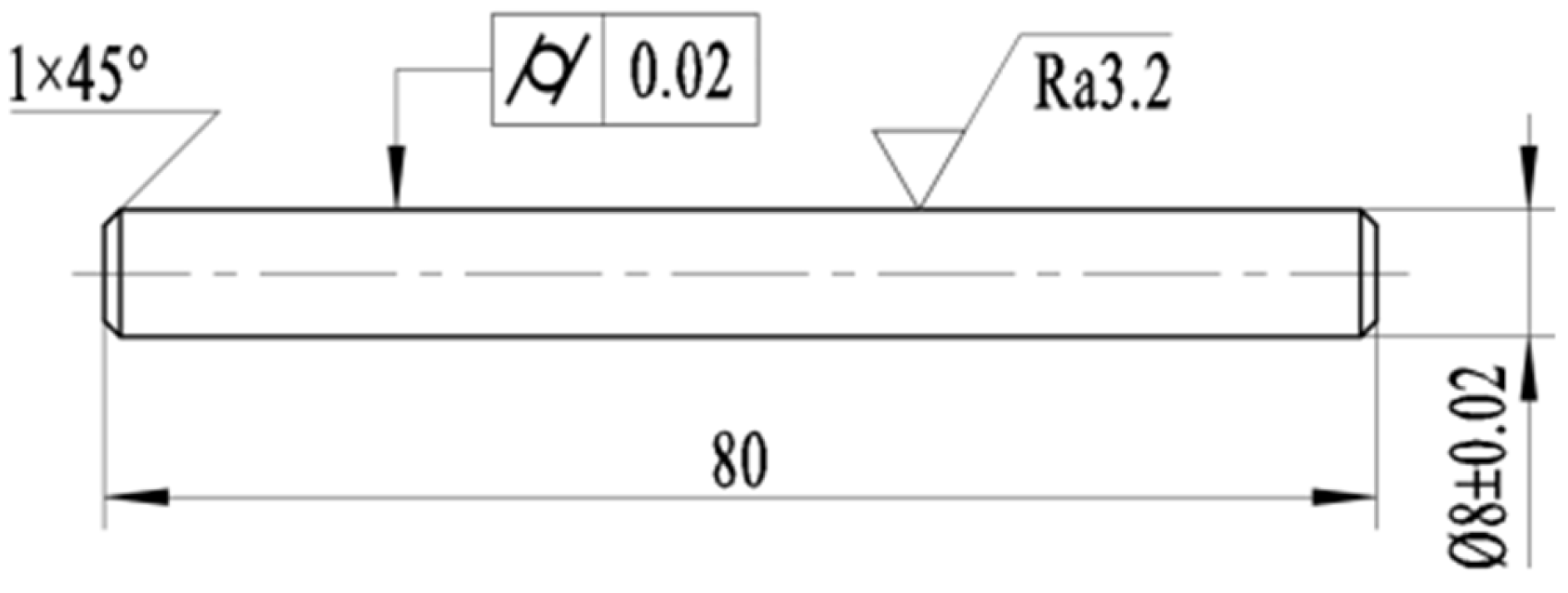
Figure 1. Schematic diagram of specimen (unit: mm).
Coatings 15 01073 g001
Figure 2. SPHE steel material properties; (a) engineering stress–strain curve; (b) grain structure of untreated specimen. The colored curve above represents three stretching experiments with the same standard tensile specimen to ensure the accuracy of the experimental data.
Coatings 15 01073 g002
Figure 3. Ultrasonic-assisted spinning specimen V-groove device overall composition schematic diagram.
Coatings 15 01073 g003
Figure 4. Schematic diagram of dynamic, static, and total loads in ultrasound-assisted spinning process.
Coatings 15 01073 g004
Figure 5. A schematic diagram of the shape of the contact surface between the ultrasonic tool head and the specimen.
Coatings 15 01073 g005
Figure 6. Schematic diagram of V-groove spin moulding; (a) spin state; (b) V-groove forming characterisation dimensions.
Coatings 15 01073 g006
Figure 7. Physical drawing of the ultrasound-assisted spinning device; the tool head first contacts the sample actuated by the pneumatic cylinder. Subsequently, the electric motor rotates the sample, thereby driving the tool head to form a V-shaped groove.
Coatings 15 01073 g007
Figure 8. Ultrasound-assisted spinning finite element model and amplitude interface settings; (a) schematic diagram of tool head and specimen assembly; (b) vibration amplitude interface settings; (c) magnitude graph.
Coatings 15 01073 g008
Figure 9. Notch depth 3D topography comparison; (a,c,e,g,i,k) are morphology of V-groove moulding at 200–700 N under static load, respectively. (b,d,f,h,j,l) are morphology of V-groove moulding at 200–700 N + UAS under static load, respectively; The figure (m) shows the depth of the V-groove under different conditions.
Coatings 15 01073 g009
Figure 10. Microstructure; (a,c,e,g,i,k) are microstructure of V-groove moulding at 200–700 N under static load, respectively. (b,d,f,h,j,l) are microstructure of V-groove moulding at 200–700 N + UAS under static load, respectively. The figure (m) is depth data of deformation layer.
Coatings 15 01073 g010
Figure 11. Comparison of microhardness data.
Coatings 15 01073 g011
Figure 12. Surface roughness.
Coatings 15 01073 g012
Figure 13. Surface residual stress under different conditions.
Coatings 15 01073 g013
Figure 14. Schematic diagram of finite element moulding accuracy results (al).
Coatings 15 01073 g014
Figure 15. Ultrasound-assisted spinning experiment notch depth and moulding angle data plot. (a) Notch depth and material flow height; green dashed portion of figure indicates trend of ultrasound-assisted reduction in groove depth for different static loads. (b) Forming angle; initial angle of tool head is 60°.
Coatings 15 01073 g015
Figure 16. Residual stress simulation and experimental results plot. The overall error between the residual stress simulation results and the experimental results is within 8%, which verifies the model’s accuracy.
Coatings 15 01073 g016
Table 1. Chemical composition content of SPHE steel.
ElementCSiMnPSAltCrCuNi
Measured value/%0.040.010.240.0110.0060.0480.0080.070.005
Standard range value/%≤0.10≤0.05≤0.50≤0.030≤0.035≥0.10≤0.015≤0.20≤0.015
Table 2. Ultrasonic process parameters of SPHE steel specimens.
Specimen GroupStatic Load (N)Ultrasonic Frequency (kHz)Amplitude (μm)
A (spinning)200, 300, 400, 500, 600, 70000
B (ultrasound-assisted spinning)200, 300, 400, 500, 600, 7002012
Disclaimer/Publisher’s Note: The statements, opinions and data contained in all publications are solely those of the individual author(s) and contributor(s) and not of MDPI and/or the editor(s). MDPI and/or the editor(s) disclaim responsibility for any injury to people or property resulting from any ideas, methods, instructions or products referred to in the content.