1. Introduction
As a type of high-strength alloy structural steel, 9310 steel is widely used in key components of aero transmission systems (such as internal splines and gears) due to its excellent hardenability, surface hardness, and fatigue strength. In the field of machining, research on 9310 steel mainly focuses on heat treatment process optimization and surface strengthening technologies [
1,
2]. The strengthening of this material relies on carburizing and quenching treatment: by increasing the surface carbon concentration, a hardened layer is formed to meet the contact fatigue strength requirements of components like internal splines and gears. After treatment and machining, its Rockwell hardness reaches HRC 58–62 [
3,
4]. However, geometric deformation caused by the heat treatment process has become a key bottleneck restricting machining accuracy.
After heat treatment, the deformation of the internal spline tooth flanks can reach 10–30 μm, far exceeding the tolerance range of less than 5 μm required for aviation-grade transmission components [
5,
6]. The main machining challenges stem from the material’s high hardness and work-hardening characteristics after heat treatment. Particularly in the precision machining of small-sized complex structural components, traditional methods face significant challenges [
7].
Although heat treatment deformation can be partially corrected through repair machining, the hardness of splines after quenching reaches above HRC60. Moreover, the small inner diameter is often less than 30 mm, and the width of the relief groove is less than 5 mm, which poses severe challenges to traditional repair methods. Furthermore, traditional methods for repairing such deformation, including manual filing, honing, and conventional grinding, have obvious drawbacks: manual filing relies on the operator’s experience, resulting in poor accuracy consistency and low efficiency; honing has limited ability to correct tooth orientation and tooth profile errors, making it difficult to compensate for large deformations; conventional grinding, due to space constraints, leads to poor accessibility of grinding wheels, easily causes overheating damage to tooth surfaces, and has poor control over the microscopic accuracy of tooth surfaces. Overall, these methods have difficulty meeting the requirements of high-precision and high-efficiency repair [
8,
9,
10].
Current solutions for addressing heat treatment deformation are primarily focused on optimizing deformation control during the heat treatment process. For example, many scholars have studied and analysed the effects of heat treatment on gear deformation. Liu et al. [
11] used finite element software to study the effect of the rectangular macrosegregation zone of the hot-rolled steel core on the heat treatment deformation of the automotive gear steel FAS3420H, and proposed rolling a square segregation zone to reduce the uneven deformation of the gear during subsequent heat treatment. Kim et al. [
12] predicted thermal deformation and residual stress through coupled simulation, and found that induction heating is very effective in reducing thermal deformation. Liang et al. [
13,
14] used the simulation data of helical gear heat treatment to establish a prediction model to predict the carbon concentration distribution and microstructure, coordinate deformation and hardening depth, and optimize the heat treatment process. Sun et al. [
15] applied the FEA-PSO-BP method to optimize the process parameters to reduce the thermal deformation during heat treatment, and obtained a set of heat treatment process parameters that can minimize the thermal deformation.
Other scholars have also used ultrasonic vibration to modify gear deformation. Ultrasonic vibration-free grinding is an advanced processing technology that combines ultrasonic vibration and free grinding. This method uses high-frequency ultrasonic vibration to give high kinetic energy to the abrasive particles, thereby achieving efficient grinding and polishing on the workpiece surface. This process significantly improves the material removal rate and processing efficiency, while optimizing the processing quality [
16,
17,
18,
19,
20]. Ultrasonic vibration technology has shown many advantages in the field of grinding and has become one of the high-tech application topics that countries focus on developing and researching. Domestic and foreign scholars have conducted systematic research on the ultrasonic vibration-free grinding technology. Based on the material removal mechanism of ultrasonic vibration grinding, Qu et al. [
21] constructed a material removal rate (MRR) prediction model based on the principle of ultrasonic vibration polishing (UVP), including abrasive micro-contact, scratch effect, and impact removal, and revealed the mechanism of MRR enhancement in UVP and the influence of parameters. The model was verified by single-crystal silicon experiments, and the results showed that the error between the predicted and measured MRR was less than 10%. Increasing the spindle speed, ultrasonic amplitude, and abrasive particle size can improve MRR while optimizing surface roughness and micromorphology. This study provides a theoretical reference and experimental basis for the prediction of UVP processing efficiency and the development of ultrasonic-assisted technology. Chen et al. [
22] studied the surface properties of alumina ceramics under different ultrasonic amplitudes, including micromorphology, friction characteristics, surface hardness, microstrain, and surface roughness, based on the principle of ultrasonic vibration-assisted polishing (UVAP). A surface roughness prediction model considering the material removal mechanism of free abrasives and fixed abrasives was established, and the model error was verified by experiments to be less than 20%. The results show that UVAP can effectively improve the surface quality of alumina ceramics, providing a theoretical basis and practical reference for subsequent UVAP processing. Zhu et al. [
23] conducted resonant energy-assisted precision machining experiments based on an improved Y9550 gear detection platform. The study confirmed that the dynamic excitation grinding process can effectively control the tooth profile deviation and significantly improve the micromorphology and surface integrity of the tooth surface. The experimental data show that the geometric accuracy of the gear pair after the optimized process is systematically improved. Zhang [
24] designed and optimized a longitudinal-torsional composite ultrasonic vibration conical transition amplitude transformer based on transfer matrix theory and finite element simulation, optimized the spiral groove parameters, and performed modal and transient dynamic analysis to verify the correctness of the theoretical calculation. Through impedance and amplitude tests and grinding experiments, it has been proven that the designed amplitude transformer has good operating performance and can significantly reduce the surface roughness of the workpiece in longitudinal-torsional ultrasonic vibration grinding. Compared with ordinary grinding, the effect is better and suitable for practical applications.
To sum up, while technologies such as ultrasonic lapping have been utilized in existing studies to improve the machining quality of surfaces, few studies have specifically addressed the unique machining characteristics of small-sized internal splines. This study innovatively applies ultrasonic vibration lapping technology to the high-precision repair of small-sized hardened internal splines, proposing a micron-level high-frequency vibration lapping method specifically designed for this application. Experimental results demonstrate that ultrasonic vibration facilitates reduced lapping resistance, decreased heat accumulation, inhibited surface burning, and effective correction of tooth profile and tooth orientation geometric errors. Complemented by the development of specialized tooling and models, this method provides an efficient and reliable solution for the high-precision repair of small-sized hardened internal splines. Theoretically, this work reveals the material removal mechanism and the regulation law of surface integrity under high-frequency vibration. In practical terms, the processing efficiency exceeds three times that of traditional manual lapping, significantly extending the service life of internal spline components.
3. Structural Design of Ultrasonic Vibration Lapping System
3.1. Design of Ultrasonic Vibrator
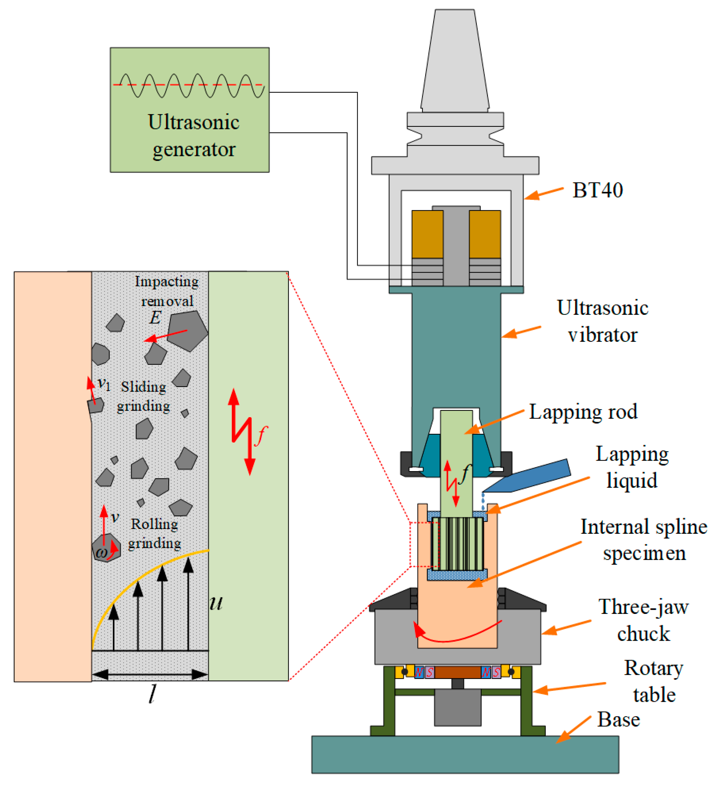
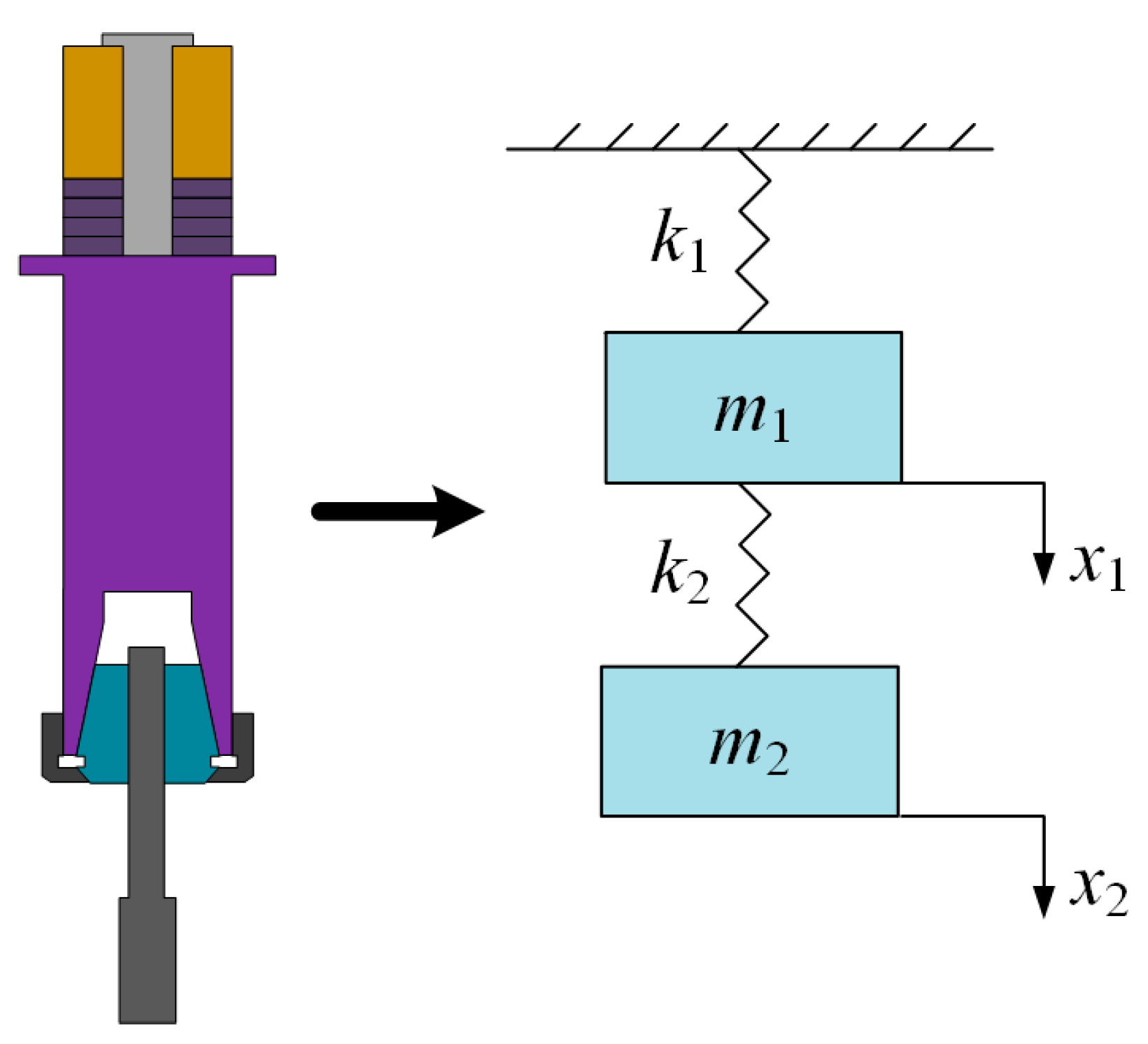
In the ultrasonic vibration lapping system, the ultrasonic vibrator and the lapping rod are its core components, as shown in
Figure 5. The ultrasonic vibrator mainly includes a rear cover plate, piezoelectric ceramics, and a front cover plate. To ensure good centering performance of the lapping rod, an ER-type spring chuck is used for the assembly of the lapping rod and the ultrasonic vibrator. During operation, the piezoelectric ceramics convert the electrical signals emitted by the ultrasonic generator into mechanical vibrations at ultrasonic frequencies, which reach the lapping rod through the front cover plate, achieving an amplitude variation effect on the lapping rod. The amplitude of ultrasonic vibration can change the energy distribution on the surface of the internal spline workpiece. Therefore, ultrasonic vibration lapping is a continuous lapping process, which can improve the lapping efficiency of workpieces.
This device adopts the form of a sandwich ultrasonic vibrator for the design of the ultrasonic vibration lapping device. The front cover plate functions to efficiently radiate the energy generated by the ultrasonic vibration from its longitudinal front surface. The rear cover plate mainly achieves unidirectional radiation when the ultrasonic vibrator end is not fixed, ensuring that as little energy as possible is radiated from the back of the ultrasonic vibrator, thus increasing the forward radiation energy of the ultrasonic vibration ultrasonic vibrator. In this paper, the materials selected for each component of the ultrasonic vibration lapping device are shown in
Table 1.
3.2. Mechanical Analysis Model of the Local Resonance System
In this study, a solid cylindrical lapping rod is selected, and the ratio of its cross-sectional area to the output cross-sectional area of the ultrasonic vibrator is strictly controlled below the 0.25 threshold, meeting the triggering conditions for local resonance. This parameter configuration follows the local resonance design criteria and has better process tolerance compared with the full resonance mode: the full resonance scheme requires all components of the system to strictly match a single resonance frequency, while geometric tolerances in actual processing tend to cause frequency detuning, thereby weakening the energy output characteristics. Under the boundary condition of the lapping rod with one end fixed and the other end free, the local resonance effect makes the amplitude of the free end significantly higher than that of the constrained end, which highlights the core value of this theory in the field of ultrasonic machining [
26].
To analyze the local resonance mechanism, a two-mass-spring dynamic model is established: the ultrasonic vibrator is equivalent to a mass block
with a stiffness coefficient
, and the lapping rod is modeled as a mass block
with a stiffness coefficient
. For the electromechanical coupling system shown in
Figure 6, this model accurately characterizes the energy transfer law in the resonant structure through decoupling vibration modes [
27].
The vibration equation of this model is:
Since the ultrasonic vibration generator emits a sinusoidal signal, assume the steady-state response of the system is:
where
is the angular frequency;
is the amplitude of the vibrator, and
is the amplitude of the lapping rod.
Solving the angular frequency equation of the system, obviously,
has two different roots, which are, respectively, as follows:
When the device is in a resonant condition at the characteristic frequency , the lapping rod and the driving end of the ultrasonic vibrator exhibit an anti-phase state with a phase difference of 180°. Moreover, as the axial dimension of the lapping rod increases, the wave impedance mismatch will significantly aggravate the difficulty of exciting local resonance. Since this incoherent resonance mode induces problems such as nonlinear attenuation of amplitude and a sharp drop in energy conversion efficiency, it has deviated from the energy coupling criteria required for ultrasonic precision machining. For this reason, this study focuses on analyzing the vibration mode characteristics in the region.
Let
represent the resonant angular frequency of lapping. Substituting into Equation (10), it can be seen that the amplitude magnification ratio of the ultrasonic vibration system is related to
,
, and
. In this paper,
,
, and
are introduced to study the effects of the system’s resonant frequency and amplitude ratio. According to Equation (10), the following relationship can be derived:
In the ultrasonic vibration system, the parameter reflects the inertial mass ratio between the ultrasonic vibrator body and the lapping rod. Experimental studies show that when the axial lengths of both are kept constant, the value of increases with the square of the cross-sectional area of the lapping rod, which mainly stems from the square-growth characteristic of mass distribution and geometric dimensions. The parameter is defined as the equivalent stiffness ratio between the lapping rod and the ultrasonic vibrator body. Its value variation has a strong correlation with the cross-sectional morphology of the component, while its sensitivity to the axial dimension is relatively weak. Specifically, under the condition that the geometric parameters of the lapping rod are constant, the change in the value is directly associated with the cross-sectional design of the ultrasonic vibrator body; when the structural parameters of the ultrasonic vibrator are fixed, the adjustment of the value is realized by changing the cross-sectional area of the lapping rod.
Therefore, when designing the ultrasonic vibration system, the influence of the diameter of the lapping rod needs to be considered, and the shape of the ultrasonic vibrator should be optimized to ensure the optimal operation of the system.
3.3. Finite Element Simulation Analysis Results
After importing the 3D model into COMSOL Multiphysics 6.1, the simulation pre-processing is completed in sequence: establishing a piezoelectric-structural coupling field model, defining the mechanical constraints of the contact interface, and configuring the material parameters. The modal analysis uses 15 kHz as the target frequency and scans the 10–20 kHz frequency band. The lapping rod is locally meshed using second-order tetrahedral elements, and the remaining components use standard grids. After verifying the independence of the grid, a high-quality discrete model containing 78,335 units is generated.
Figure 7 shows that the grid density in the key area meets the accuracy requirements. After obtaining the vibration mode of the system through the frequency domain solver, the characteristic frequencies and vibration mode parameters of each order are extracted.
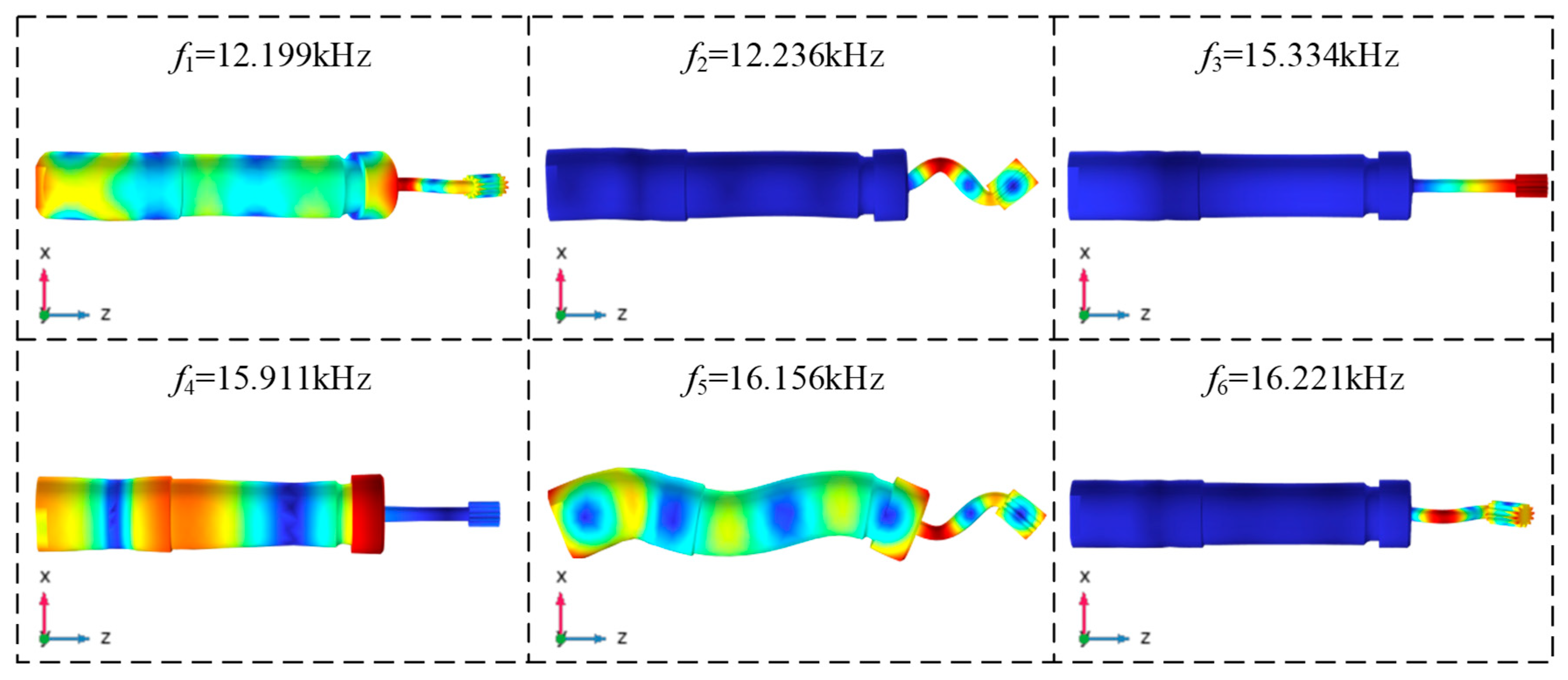
When performing modal analysis in COMSOL, the sweep frequency range is set to 12–18 kHz to determine all vibration modes of the structure. As shown in
Figure 8, vibration modes at different frequencies can be obtained to help evaluate the resonance characteristics of the ultrasonic vibration system and provide a basis for further optimization design.
According to the modal characteristics of
Figure 8, the ultrasonic vibrator presents six typical resonance forms in the 12–18 kHz frequency band. By analyzing the spatial distribution of the vibration vector at the end of the lapping rod, it can be seen that when the excitation frequencies are at 12.199 kHz, 12.236 kHz, 16.156 kHz and 16.221 kHz, the vibration system produces differential bending deformations in the X/Y axis of the Cartesian coordinate system, and the end of the lapping rod presents the maximum flexural displacement. It is worth noting that under the 15.911 kHz working condition, the exciter presents radial standing wave vibration characteristics, at which the center displacement of the end of the lapping rod is the smallest and the edge forms the maximum amplitude distribution. At the characteristic frequency of 15.334 kHz, the system exhibits a unique axial full-wave resonance characteristic, which is specifically manifested as the longitudinal amplitude of the exciter reaches a peak value, while the longitudinal displacement of the ultrasonic vibrator approaches zero. The displacement cloud diagram shows that a full-wavelength resonance mode is formed under this working condition, the main energy is concentrated in the longitudinal vibration component, and a significant local resonance effect is produced at the end of the tool. The frequency deviation between the resonant frequency and the theoretical design value is 2.23%. After analysis, it was found that the deviation originated from the equivalent treatment of auxiliary components such as the ultrasonic vibrator rear cover, ER32 collet, and nut model during modeling. This difference range verifies the reliability of the core vibration theory model.
In summary, the 15.334 kHz mode corresponds to the pure longitudinal vibration of the lapping rod, with its vibration vector distributed along the axial direction of the lapping rod. The amplitude at the rod’s end is uniform, enabling efficient energy transfer to the tooth surface. In contrast, modes such as 12.199 kHz, 12.236 kHz, 16.156 kHz, and 16.221 kHz are X/Y-axis bending vibrations, which cause radial deflection of the lapping rod and lead to interference between the lapping rod and the internal spline during the lapping process. For the 15.911 kHz mode, the central displacement at the rod’s end is close to zero, making it unable to drive abrasive particles for effective impact. Therefore, the longitudinal mode at 15.334 kHz is the only and most suitable option for the lapping process of small-sized internal splines.
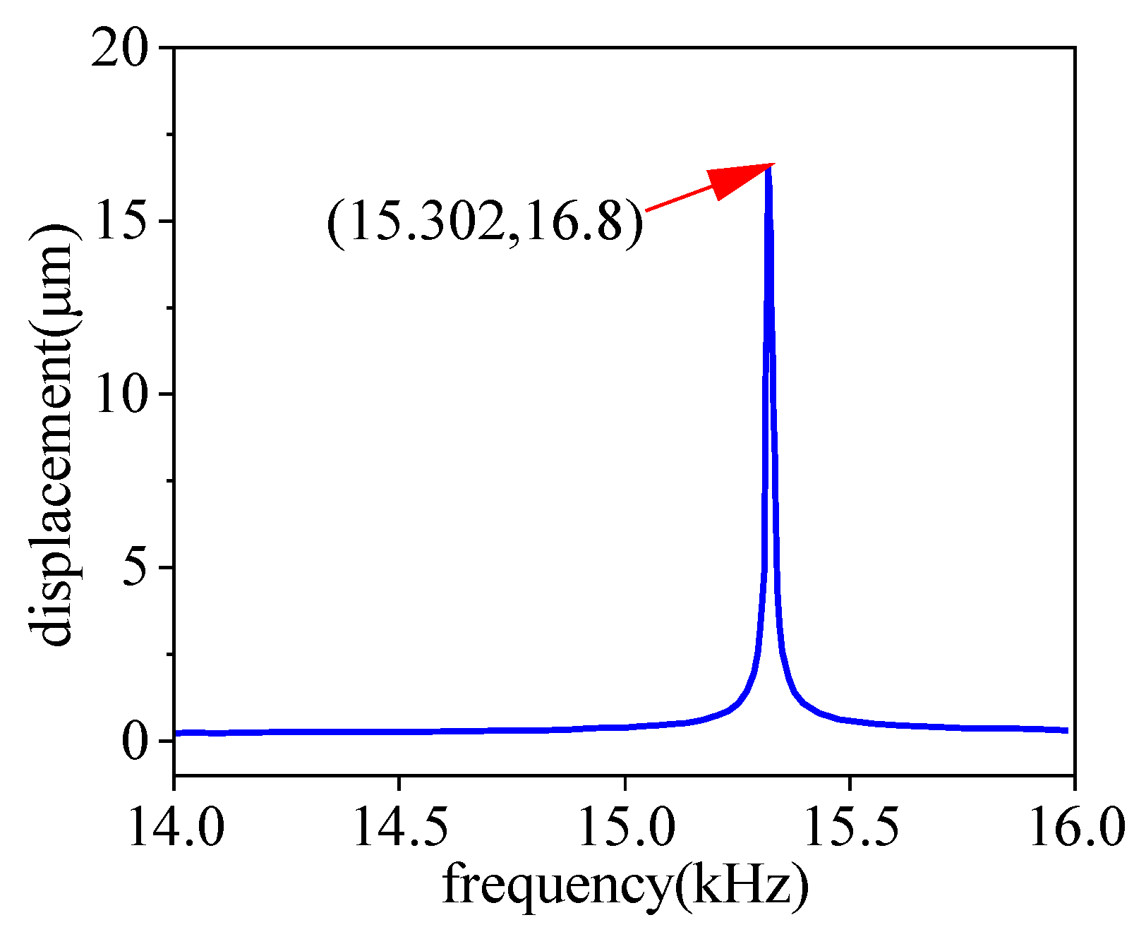
When performing the frequency response characteristics study of the ultrasonic vibrator on the COMSOL multi-physics simulation platform, a time-harmonic potential excitation with an amplitude of 300 V was applied to the piezoelectric ceramic (the negative pole was grounded), a 14–16 kHz sweep frequency range was set, and a 10 Hz frequency step value was used for parameter scanning. In the numerical post-processing process, the amplitude of the vibration response of the geometric center node at the end of the lapping rod was extracted, and the amplitude-frequency response spectrum was constructed based on this (as shown in
Figure 9). The simulation data revealed significant nonlinear mutation response characteristics: when the driving frequency deviated from the characteristic frequency of 15.302 kHz, the amplitude of the center point decayed to below the micron level; and when approaching the critical frequency, the amplitude increased sharply, and finally, a longitudinal vibration peak of 16.8 μm was measured at 15.302 kHz. This typical amplitude-frequency response curve shape confirms that the system has a strong resonance effect at this characteristic frequency point.
This curve clearly illustrates the resonance characteristics of the system within the 14–16 kHz frequency band: when the frequency approaches 15.302 kHz, the amplitude surges sharply from the micrometer level to a peak of 16.8 μm, forming a sharp resonance peak. The deviation from the simulated target frequency of 15.334 kHz is merely 0.2%, which verifies the system’s strong resonant response at the target frequency. When deviating from this frequency, the amplitude rapidly attenuates to below 5 μm. The shape of this typical amplitude-frequency response curve confirms that the system exhibits a strong resonance effect at this characteristic frequency point.
3.4. Dynamic Stability and Energy Transfer Optimization of Substructure
In the ultrasonic vibration lapping system, the ultrasonic vibrator connects to the BT40 spindle via a mounting flange. If the flange deviates from the standing-wave node plane, the BT40 spindle will generate parasitic vibration, with part of the mechanical energy dissipating as thermal energy. This causes a temperature rise at the connection and weakens the effective amplitude at the lapping tool end. More critically, the uncontrolled vibration of the BT40 spindle transmits to the machine tool spindle system, inducing motion errors like radial runout and axial play, directly affecting machined surface quality. Thus, multi-physical field simulation is used to perform modal analysis on the flange installation position, improving its dynamic stability through optimization.
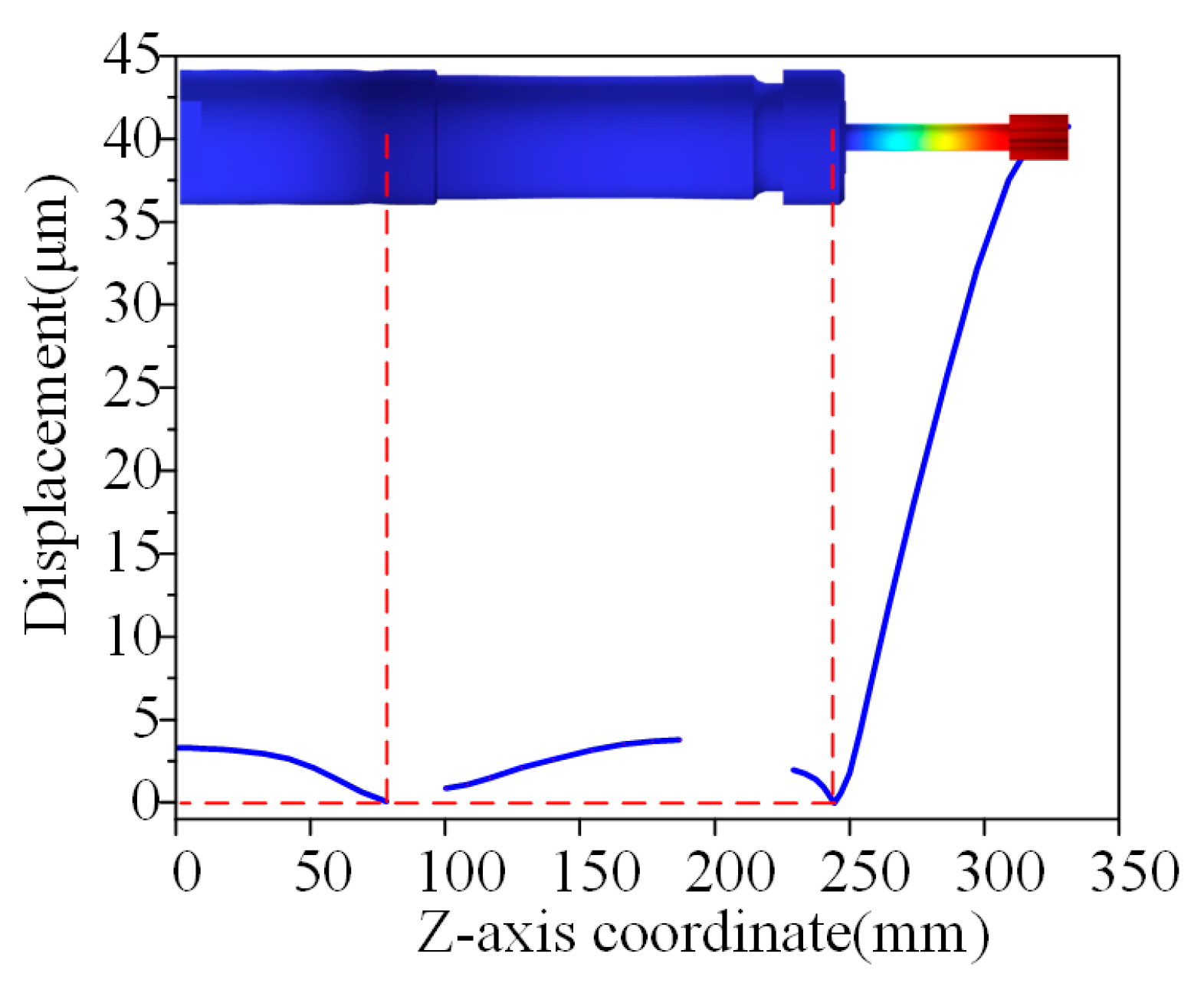
According to the vibration characteristic cloud map in
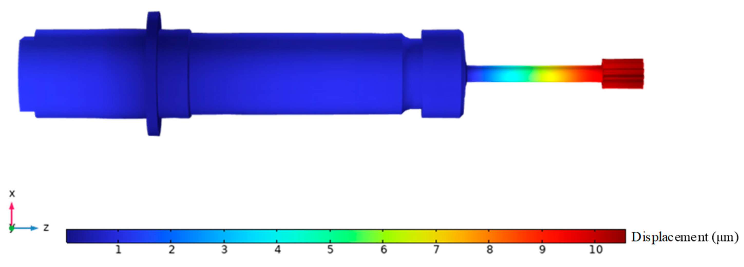
Figure 10, the system has two key nodal regions: one at the contact interface between the piezoelectric ceramic stack and the front cover, and the other at the fixed end of the collet chuck. Accordingly, the mounting flange is arranged at the tail end of the front cover. By analyzing the longitudinal displacement distribution along the axial centerline of the ultrasonic vibrator, a coordinate system with the end face of the ultrasonic vibrator’s rear cover as the Z-axis origin is established, and the axial displacement distribution curve is plotted. The results show that solving the zero-point of vibration amplitude can accurately locate the nodal plane in the full-wave resonance state, with corresponding axial positions of 75 mm and 240 mm. This data provides key spatial constraints for flange structure optimization.
After completing node positioning and clamping mechanism configuration, the operating frequency stability and dynamic response amplitude of the ultrasonic vibration lapping device did not exhibit significant attenuation. The flange structure was accurately arranged at the tail end of the front cover plate, with full-degree-of-freedom constrained boundary conditions applied to it, followed by modal characteristic analysis. The vibration energy distribution characteristics of the system under these constraint conditions are shown in
Figure 11, and the mode shape cloud map clearly presents the distribution law of the displacement field of the ultrasonic vibrator in the full-wave resonance state.
According to the mode shape analysis results in
Figure 11, after adding the flange structure, the tool end of the system exhibits a local resonance phenomenon under the 15.513 kHz working condition, with a 0.176 kHz frequency deviation compared to the numerical model without flange configuration. This deviation stems from the fact that in the finite element analysis process, node positioning is based on interval locking of the vibration displacement polarity conversion interval, making it impossible to achieve accurate capture of the absolute zero displacement point, which leads to inherent deviations in natural frequency calculation. Experimental data show that the deviation amount is within the allowable range, fully verifying the effectiveness of the flange structure design.
5. Results and Discussion
5.1. Analysis of Detection Results for Internal Splines After Traditional Manual Lapping
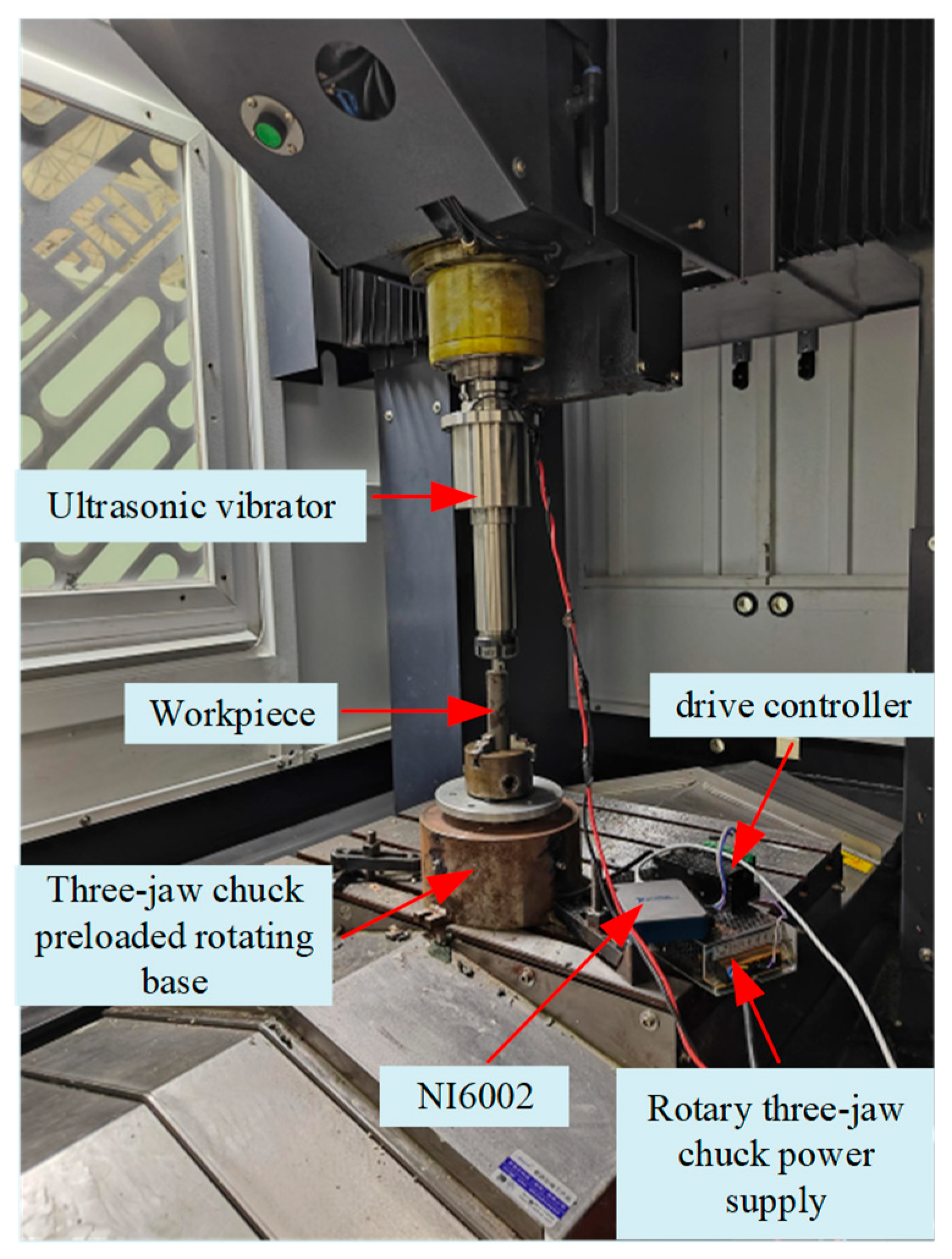
In the field of precision machining for small-sized internal splines, the traditional lapping process mainly relies on manual lapping. Although this process is suitable for small-batch production or high-precision repair scenarios, it requires standardized operations to improve the tooth flank accuracy. The specific procedure is as follows: First, the internal spline workpiece is clamped on a specialized fixture to ensure its axis is horizontal, thereby avoiding lapping deviations. Subsequently, an abrasive paste suitable for the lapping requirements is selected and evenly applied to the tooth flanks and tooth spaces of the lapping mandrel, which is fully matched with the workpiece in terms of tooth profile, module, and number of teeth. After that, the operator holds both ends of the lapping mandrel with both hands, drives it to rotate at a moderate speed, and simultaneously performs a reciprocating motion along the axial direction, applying uniform and appropriate pressure during the process. During lapping, the residual abrasive paste must be cleaned regularly; the operator observes the tooth flank marks and burrs visually, adjusts the operation rhythm and pressure in a timely manner, until the internal spline tooth flanks are regular and the fit clearance meets the tolerance requirements.
Obviously, this traditional process has significant limitations in multiple aspects: First, the processing efficiency is low. The entire process relies on manual control, and the lapping time per workpiece is long, making it unable to meet mass production needs. Second, the accuracy and stability are poor. The operation force and speed are easily affected by the operator’s fatigue level and skill proficiency, leading to large fluctuations in workpiece accuracy and insufficient consistency. Third, the labor intensity is high. Operators need to maintain stable movements for a long time, which is prone to fatigue and may cause defects such as tooth flank scratches and tooth profile distortion.
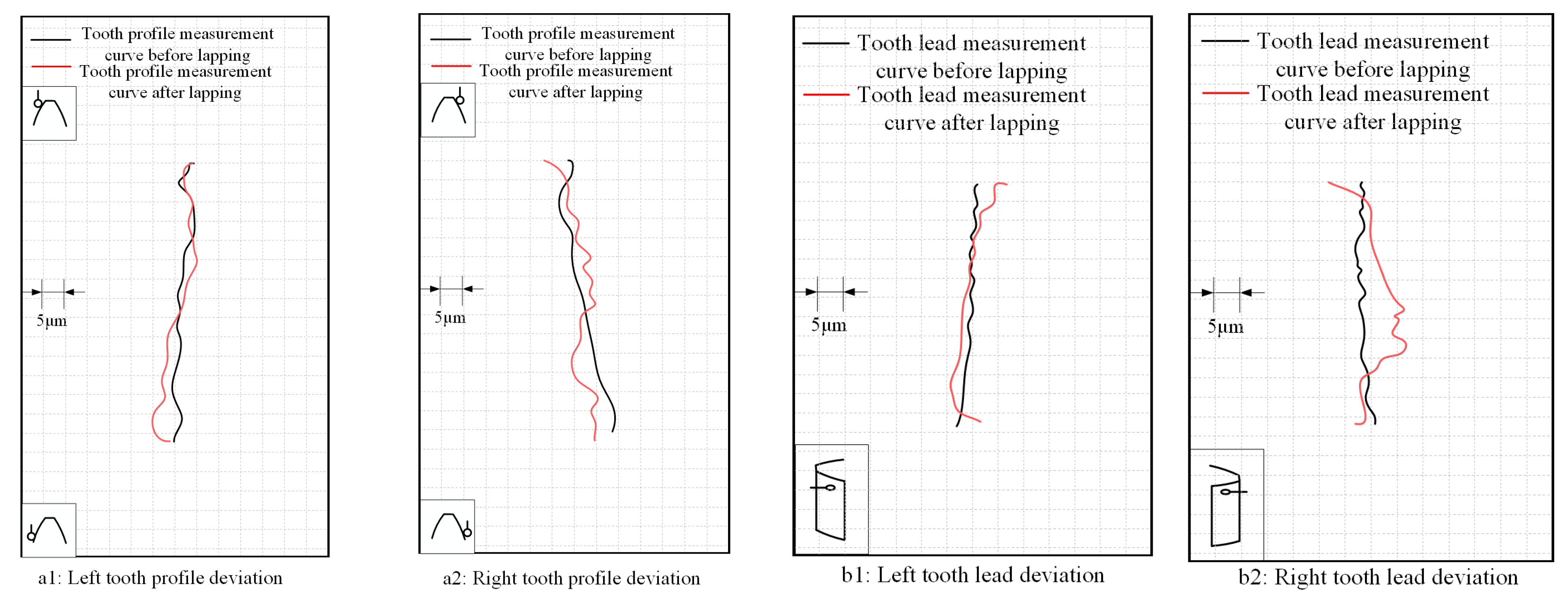
As shown in
Figure 14, a typical sample from the manually lapped internal splines was selected as a representative to analyze the changes in tooth profile and tooth lead deviations of its left and right tooth flanks before and after manual lapping. The black lines represent the deviations of the internal spline before manual lapping, and the red lines represent the deviations after manual lapping. Under ideal conditions, the tooth profile and tooth lead of a high-precision tooth should approximate a vertical straight line when measured. According to the inspection report, after manual lapping, the tooth profile and tooth lead deviations of the internal spline show the characteristic of non-uniform correction: in some areas of the red line (after lapping), the fluctuations converge due to local lapping; in some areas, almost no change occurs due to the formation of unlapped blind areas caused by uneven fitting; in even some areas, the fluctuations intensify due to over-lapping. Additionally, the symmetry of the left and right tooth flanks is poor, and the overall shape still deviates significantly from the ideal vertical straight line, indicating that the correction effect is chaotic and has low controllability.
5.2. The Influence of Ultrasonic Vibration Lapping on Tooth Profile Deviation
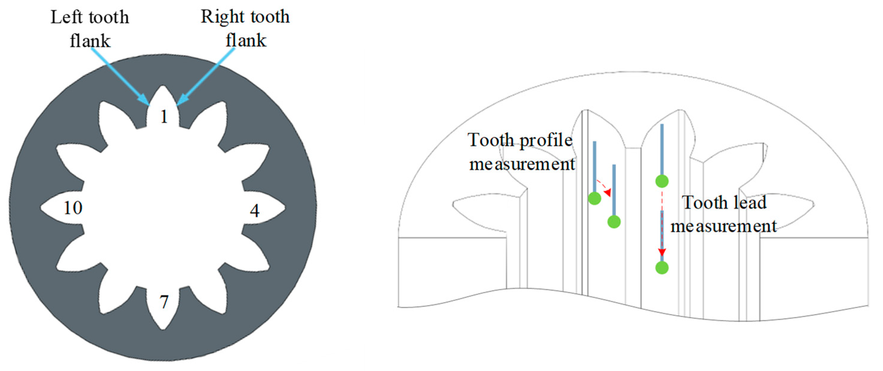
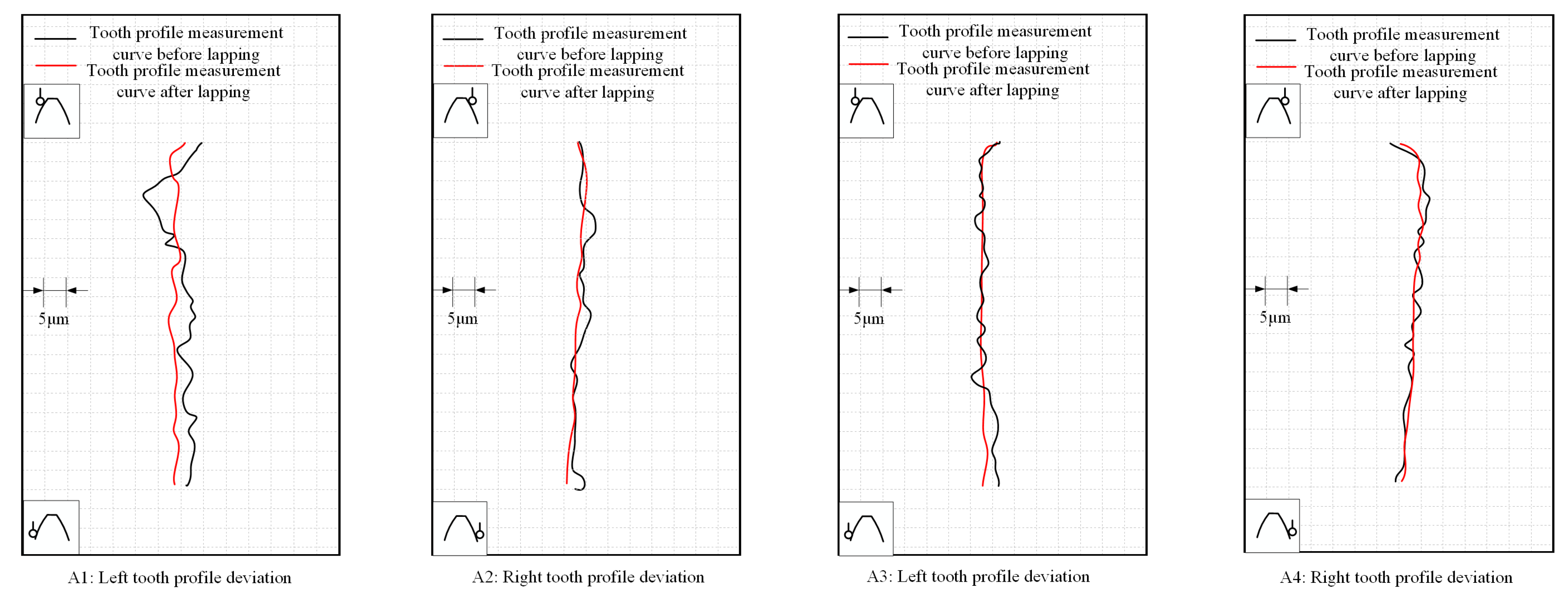
In the lapping inspection report, the changes in tooth profile deviation before and after lapping can be presented more intuitively. In this study, a typical sample from the experiments was selected for analysis. As shown in
Figure 15, this report analyzes the changes in tooth profile deviation of the tooth flanks on both sides of two randomly selected pairs of teeth in the internal spline sample after lapping. The black lines represent the tooth profile deviation of the internal spline before lapping, while the red lines represent that of the internal spline after lapping.
Under ideal conditions, when a high-precision tooth is measured, its tooth profile should approximate a vertical straight line. It can be seen from the inspection report that the black lines—representing the unlapped state—have a shape similar to a wave line with severe fluctuations; after lapping, the red lines are corrected to a form that is closer to the ideal straight line.
On one hand, lapping improves macroscopic shape accuracy; on the other hand, symmetric correction is applied to the tooth flanks on both sides of the same pair of teeth, enhancing tooth flank symmetry. This process, through the vibratory lapping of abrasive particles, demonstrates the process capability of uniformly correcting tooth profile deviations, verifying the core value of lapping in high-precision spline machining.
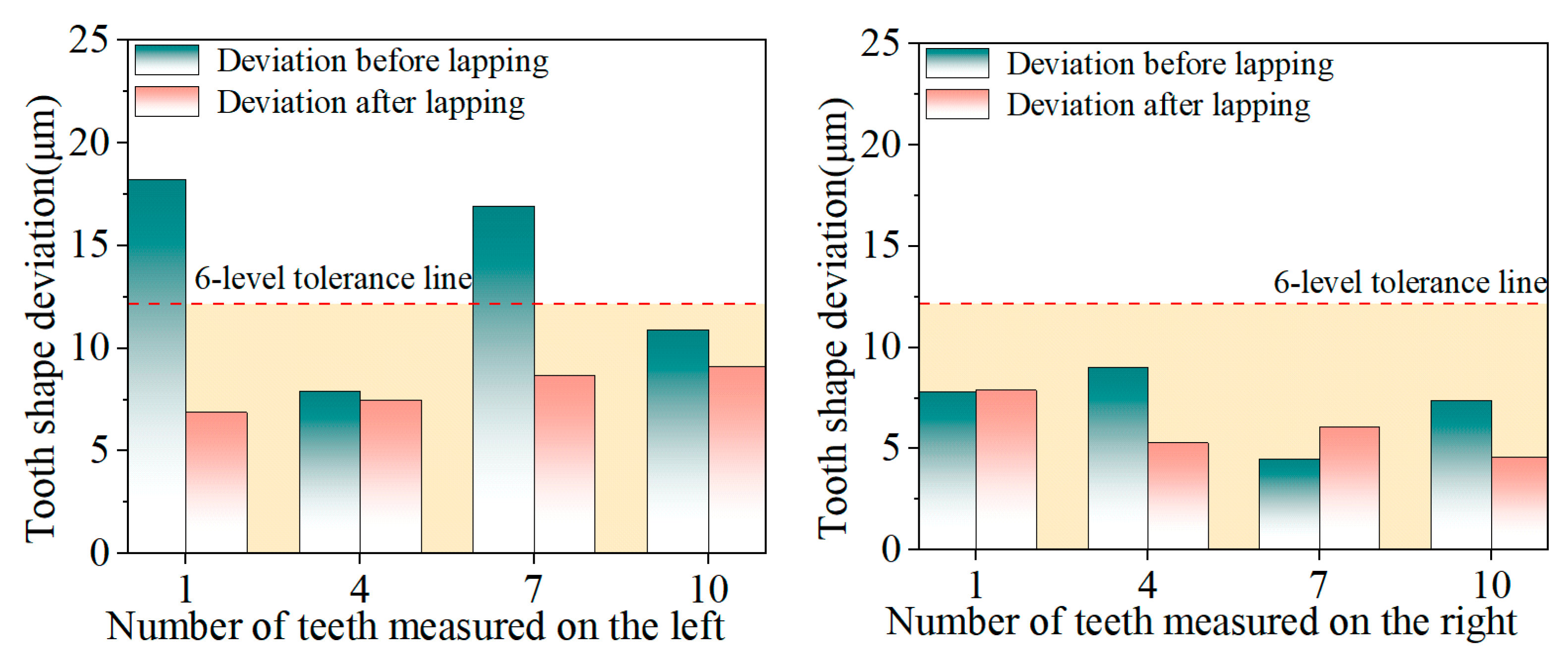
The tooth profile deviation of the internal spline directly affects the meshing accuracy with the external spline. As shown in
Figure 16, the experimental results show that after ultrasonic vibration lapping, both the total tooth profile deviation and total tooth orientation deviation of the internal spline meet the grade 6 accuracy requirements specified in GB/T 3478.1-2008 Cylindrical Straight-Tooth Involute Splines (Metric Module, Side Fit) Part 1: General, reaching grade 6 accuracy [
28]. Ultrasonic vibration has a strong correction ability for teeth with large tooth profile deviations. The tooth profile deviation of the 1st tooth measured on the left side of the internal spline decreased from 18.2 μm to 6.9 μm, with a maximum reduction of 11.3 μm. This shows that ultrasonic vibration makes the lapping abrasive particles vibrate on the surface of the internal spline through high-frequency vibration during the lapping process. For the tooth surface with large tooth profile changes, the distance between the lapping rod and the internal spline surface is small, so the tooth profile correction ability is strong. The tooth surface with a large tooth profile deviation before lapping has a greater decrease in deviation after ultrasonic vibration lapping. For teeth with small tooth profile deviation, the tooth profile deviation after lapping may increase due to uneven lapping paste, but they all meet the 6-level tolerance requirements.
During the lapping process, the tooth profile surface of the internal spline is evenly trimmed, which ultimately leads to an overall reduction in tooth profile deviation, especially the tooth surface with large deviation, whose shape is closer to the ideal profile. This is of great significance to the performance of the internal spline in actual use. The precise tooth shape can improve the fitting accuracy and service life, thereby improving the reliability and durability of the entire transmission system.
5.3. The Influence of Ultrasonic Vibration Lapping on Tooth Lead Deviation
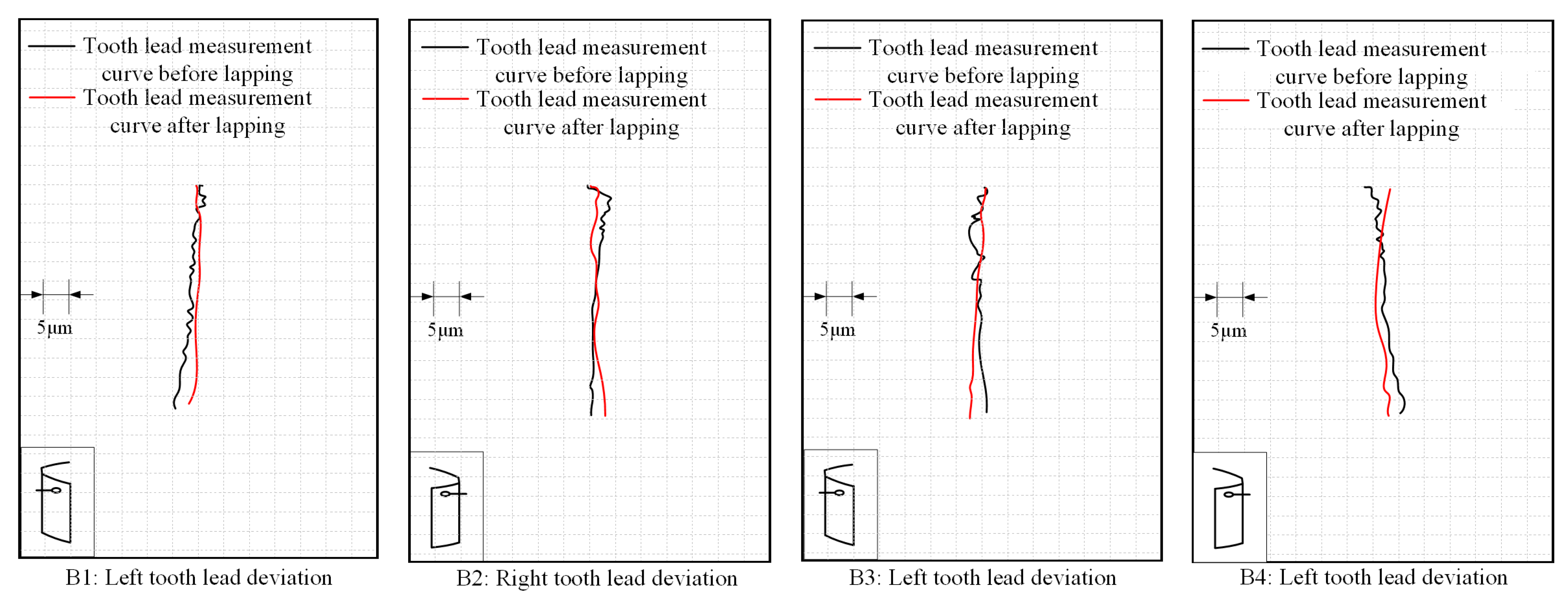
In the lapping inspection report, the changes in tooth lead deviation before and after lapping can be presented more intuitively. In this study, a typical sample from the experiments was selected for analysis. As shown in
Figure 17, this report analyzes the changes in tooth lead deviation of the tooth flanks on both sides of two randomly selected pairs of teeth in the internal spline sample after lapping. The black lines represent the tooth lead deviation of the internal spline before lapping, while the red lines represent that of the internal spline after lapping.
Under ideal conditions, when a high-precision tooth is measured, its tooth lead (deviation curve) should approximate a vertical straight line. It can be seen from the inspection report that the black lines—representing the unlapped state—have a shape similar to a wave line with severe fluctuations; after lapping, the red lines are corrected to a form that is closer to the ideal straight line.
Meanwhile, after lapping, the tooth lead curves of the two flanks of the same pair of teeth show more consistent deviation patterns, demonstrating a symmetric correction effect. Through the vibratory lapping of abrasive particles, this process simultaneously improves the macroscopic shape accuracy and microscopic fluctuations of tooth lead, verifying the process value of lapping in correcting errors and improving consistency during high-precision spline tooth lead machining.
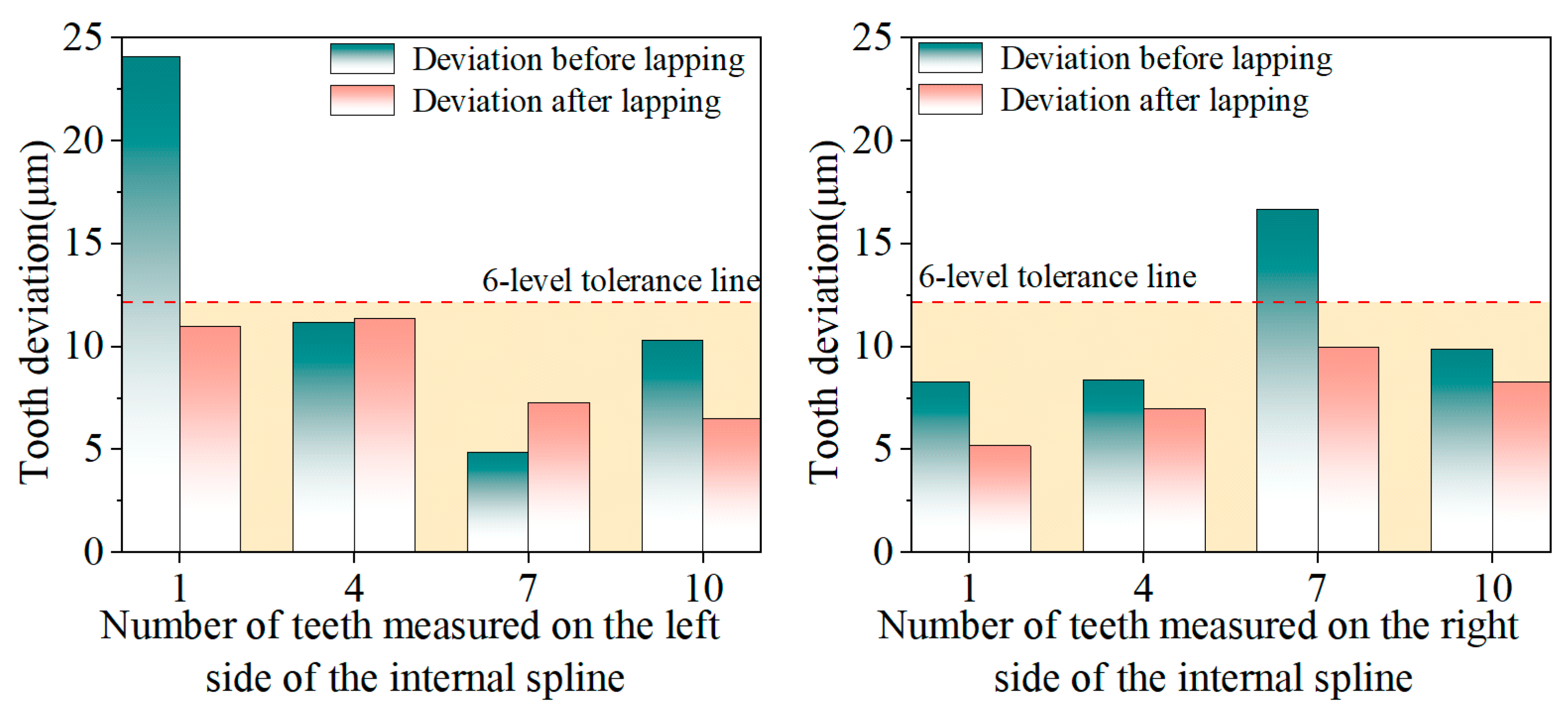
As shown in
Figure 18, the experimental results indicate that after ultrasonic vibration lapping treatment, the internal spline with large tooth lead deviation can effectively reduce such deviation. The maximum tooth lead deviation decreased from 24.1 μm to 11 μm, with a reduction of 13.1 μm. This shows that ultrasonic vibration lapping, through high-frequency vibration, enables more uniform contact between lapping abrasives and the internal spline surface, thereby improving the shape accuracy of the internal spline tooth surface. Similar to tooth profile deviation, ultrasonic vibration lapping has a more obvious effect on tooth surfaces with larger pre-lapping orientation deviations. The reason is that for tooth surfaces with larger deviations, due to their higher surface irregularity, they are subjected to greater impact force from ultrasonic vibration lapping, resulting in a faster material removal rate, and ultimately making the tooth lead shape more uniform and precise. During the ultrasonic vibration lapping process, the high-frequency vibration of ultrasonic waves not only increases the kinetic energy of the lapping medium but also effectively reduces the friction and resistance between the lapping medium and the workpiece surface.
6. Conclusions
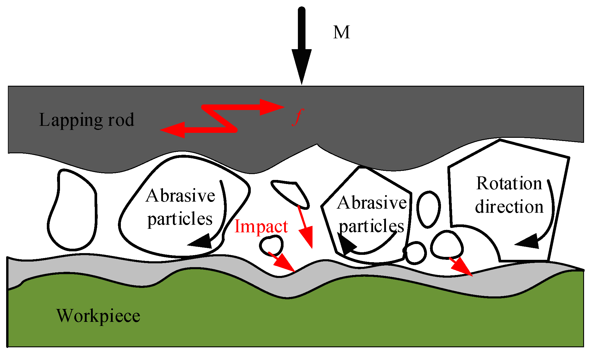
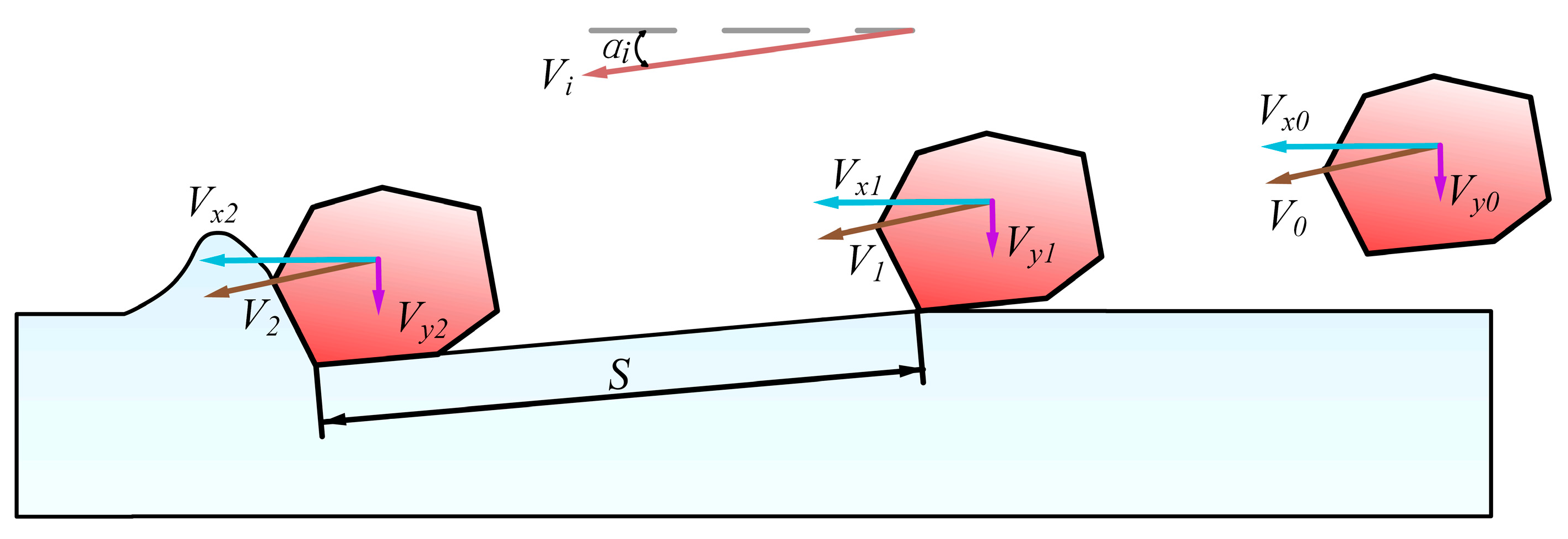
Aiming at the problems of difficult precision repair and low processing efficiency of 9310 internal splines after heat treatment in traditional lapping, this paper proposes an efficient lapping technology based on ultrasonic vibration. By establishing the liquid abrasive impact trajectory model and the rolling abrasive material removal model, the synergistic mechanism of micro-cutting and abrasive impact under ultrasonic vibration was revealed. The longitudinal ultrasonic vibration system is designed and optimized. The simulation and experimental verification show that its resonant frequency is 15.334 kHz, and the system performance is stable and reliable.
Verification experiments of ultrasonic vibration lapping were conducted on 9310 internal spline samples after heat treatment on the experimental platform. The results show that, compared with traditional manual lapping, this ultrasonic vibration lapping process significantly reduces the tooth profile and tooth lead deviations: the maximum tooth profile deviation decreases from 18.2 μm to 6.9 μm, and the maximum tooth lead deviation decreases from 24.1 μm to 11.0 μm. Furthermore, this process ensures that both the total tooth profile deviation and total tooth lead deviation of the internal splines meet the Grade 6 accuracy requirements specified in GB/T 3478.1-2008 Cylindrical Straight-Tooth Involute Splines (Metric Module, Tooth Side Fit)—Part 1: General. The research results show that ultrasonic vibration lapping can achieve high-precision repair of high-hardness, small-sized complex structural components, and has significant engineering application potential, providing an innovative solution for the high-quality repair of aviation transmission components.
