Abstract
As manufacturing demands for challenging-to-machine metallic materials continue to evolve, the performance of cutting tools has emerged as a critical limiting factor. The synergistic application of micro-texture and coating in cutting tools can improve various properties. For the processing of existing micro-texture, because of the fast cooling and heating processing method of laser, there are defects such as remelted layer stacking and micro-cracks on the surface after processing. This study introduces a preheating-assisted technology aimed at optimizing the milling performance of textured coated tools. A milling test platform was established to evaluate the performance of these tools on titanium alloys under thermally assisted conditions. The face-centered cubic response surface methodology, as part of the central composite design (CCD) experimental framework, was employed to investigate the interaction effects of micro-texture preparation parameters and thermal assistance temperature on milling performance. The findings indicate a significant correlation between thermal assistance temperature and tool milling performance, suggesting that an appropriately selected thermal assistance temperature can enhance both the milling efficiency of the tool and the surface quality of the titanium alloy. Utilizing the response surface methodology, a multi-objective optimization of the textured coating tool-preparation process was conducted, resulting in the following optimized parameters: laser power of 45 W, scanning speed of 1576 mm/s, the number of scans was 7, micro-texture spacing of 130 μm, micro-texture diameter of 30 μm, and a heat-assisted temperature of 675.15 K. Finally, the experimental platform of optimization results is built, which proves that the optimization results are accurate and reliable, and provides theoretical basis and technical support for the preparation process of textured coating tools. It is of great significance to realize high-precision and high-quality machining of difficult-to-machine materials such as titanium alloy.
1. Introduction
The advancement of aerospace, automotive, and other manufacturing sectors has introduced significant challenges regarding the processing quality and efficiency of difficult-to-machine metallic materials. The performance of cutting tools has become a critical factor that constrains the progress of these industries. The synergistic effects of micro-texturing and coating on tools can enhance lubrication properties, reduce friction resistance, improve wear and thermal resistance, and facilitate chip removal [1,2]. However, employing laser technology for the non-contact preparation of micro-textures presents challenges such as melt recasting and thermal effects. To address these limitations, alternative technologies, including ultrasonic vibration and electromagnetic composite field techniques, have been proposed [3,4]. However, the cost of both technologies is high. In order to choose a cheaper and more convenient way to optimize the preparation of micro-texture, it is proposed to optimize it by preheating. At present, in the field of micro-texture preparation, it has been proved that preheating can suppress the cracks caused by laser shock in quantity and depth, and the heat-affected zone of the bowl has also been improved [5,6]. It is intended to optimize the milling state of the textured coating tool and prolong the working life of the micro-texture and coating by preheating assisted technology combined with micro-texture preparation technology.
Current research on the application of micro-texture and coating technology to tool surfaces has been conducted by Wang et al. [7], who examined the effects of laser processing parameters on the surface morphology, geometric dimensions, and surface composition of mixed textures. The experimental findings indicate that the structure of the bottom and side walls of the textured coated tools is primarily composed of oxides. When laser parameters are judiciously selected, the integrity of the coating, along with the surface texture of the tool, remains intact. Furthermore, investigations into the laser fabrication process of mixed micro-textures on coated tools reveal that the regulation of texture width and depth is crucial for the successful development of micro-textured tools. Jiang Yu et al. [8] employed finite element analysis to evaluate the cutting performance of TiC-coated micro-textured tools during the machining of AlSi1045. Through a comparative analysis of equivalent stress, cutting forces, and cutting temperature during milling processes using micro-textured tools with and without TiC coating, it was revealed that the coated micro-textured tools significantly enhanced machining performance. Additionally, Xin Liu [9] explored the cutting performance of various coatings in conjunction with micro-textured tools, concluding that the application of coatings effectively mitigates thermal damage. The introduction of micro-textures on the rake face of the tool also contributes to a reduction in cutting force, cutting temperature, and surface adhesion on the rake face, thereby extending tool life. Qinghua Li [10] conducted experiments to investigate the impact of various micro-texture shapes, including concave–convex and staggered designs, on cutting performance. The results reveal that each shape has distinct advantages and disadvantages, indicating that no universally optimal solution exists; instead, the selection of micro-texture must be tailored to the specific working environment. The micro-textured coating material enhances cutting performance by providing protection during collisions, due to its high hardness and chemical stability. Furthermore, the study demonstrates that optimizing the microstructure combination of the coating material significantly improves the cutting performance of aluminum alloys. The use of two distinct tool types facilitates easier chip fragmentation, resulting in a 25% reduction in cutting force and a 9.09% decrease in temperature compared to non-micro-textured tools. Additionally, when compared to uncoated composite structures, there is a 3% reduction in temperature and a 4.99% decrease in cutting force. Haochuan Yang [11] examined the role of micro-textures on tool surfaces, noting their ability to resist wear, reduce friction, capture impurities, and enhance both cutting performance and work quality. However, the study also highlights that the range of process parameters and micro-texture parameters for micro-textured coated tools is limited, which can hinder processing efficiency and increase costs. Through milling experiments, a highly accurate predictive model was developed, demonstrating that cutting force, tool wear, and workpiece surface roughness are influenced not only by cutting parameters but also by the parameters involved in micro-texture. Wang et al. [12] studied the machining performance and tool wear of AlCrN/TiAlN-coated cemented carbide tools during Ta-2.5W milling. The wear resistance of AlCrN-coated tools is better than that of TiAlN-coated tools. The main wear mechanisms of the two tools are crater wear, adhesive wear and diffusion wear. The cutting force of the AlCrN-coated tool is reduced by 1% to 15%, and the surface roughness is reduced by 6% to 20%. The cutting speed in the range of 80–120 m/min can ensure lower cutting force and maintain good surface roughness. Manit Timata et al. [13] explored the variation of exit burr height (EBH) value with drilling time during the specific hole drilling process of forged brass workpieces with or without AlCrN-coated WC drill bit to produce water valve parts. The results show that the predicted tool life of AlCrN-coated WC drill bit is higher than that of uncoated WC drill bit, and the tool life of AlCrN-coated WC drill bit is increased by 30%.
The current research landscape regarding preheating in surface treatment reveals that its role extends beyond fundamental theoretical investigations to encompass studies on practical machining applications. By analyzing the effects of preheating technology on surface-treatment outcomes and clarifying the underlying mechanisms, researchers can devise more effective and efficient strategies for surface treatment. In the realm of laser cladding surface treatment, Liang Feilong et al. [14] have successfully improved the corrosion resistance and service life of 316 L substrates in marine environments. They achieved this by applying laser cladding to create a Ni-based WC/CeO2 composite coating, which was further optimized through preheating and remelting treatments. The results indicate that preheating reduces crack formation in the coating and enhances its resistance to pitting corrosion. Moreover, the remelting treatment promotes a more uniform decomposition of WC particles, thereby increasing both hardness and corrosion resistance. Notably, at a preheating temperature of 350 °C, the remelted coating exhibits superior wear and corrosion resistance. Preheating and remelting treatments enhance the coating’s corrosion resistance and wear resistance by suppressing crack formation and generating fine carbide particles, respectively. Guo et al. [15] utilized laser cladding technology to create an iron-based cladding layer on the surface of 27SiMn steel, examining the impact of preheating on the microstructure and mechanical properties of the heat-affected zone. The findings reveal a significant presence of martensitic structures within the heat-affected zone, with tensile fractures displaying characteristics of quasi-cleavage. The application of preheating treatment has been shown to reduce martensite content while promoting the formation of pearlite structures. Specifically, at a preheating temperature of 100 °C, the hardness of the quenching layer decreased by 25.4%, whereas elongation increased by 11.5%, and tensile strength decreased by 14.3%. Furthermore, at a preheating temperature of 300 °C, the fracture mode transitioned to ductile fracture. These results suggest that appropriate preheating can effectively diminish the martensitic structure and alleviate the reduction in toughness. Yang et al. [16] investigated the effect of preheating on laser-clad Co-based alloy coatings. Laser cladding was performed on ER9 wheel materials without preheating and with preheating at 200 °C. The microstructure, elemental/phase composition, and hardness variations of the clad layers were analyzed using optical microscopy (OM), scanning electron microscopy (SEM), energy-dispersive spectroscopy (EDS), X-ray diffraction (XRD), and a Vickers hardness tester. The results revealed that the clad layers primarily consisted of γ-Co and Cr23C6 phases, with an increase in γ-Co diffraction peak intensity observed after preheating. Preheating enabled the formation of crack-free clad layers but led to increased grain size. The average hardness values of the un-preheated and preheated clad layers were 464.2 HV and 329.8 HV, respectively, both exceeding the substrate hardness of 293.2 HV. Mustafa Kuntoğlu [17] posited that techniques such as substrate heating, powder preheating, and rescanning can effectively mitigate residual stress during the selective laser melting (SLM) process. These methods not only reduce surface porosity but also enhance production efficiency and lower costs by diminishing the necessity for rescanning. Lajis [18] investigated the impact of preheating on cemented carbide-coated inserts in vertical milling and discovered that preheating temperature significantly influences tool wear and surface finish. An increase in the preheating temperature of the co-working material can markedly decrease the tool wear rate, extend tool life, and improve surface roughness, potentially eliminating the need for subsequent grinding and polishing operations. Li Xinyu et al. studied the combination of thermal assisted machining and laser technology, and explored the influence mechanism of thermal assisted temperature on the surface morphology, element distribution and mechanical properties of micro-textured cemented carbide. The results show that the thermal assisted process effectively reduces the residual stress and temperature gradient during laser processing. The wear resistance and anti-friction performance of the tool surface are improved, and the milling force, noise, tool wear and surface roughness of the workpiece are also reduced.
In general, the research status of preheating in surface treatment shows that its role is not only limited to basic theoretical research, but also covers specific processing application research. By exploring the influence of preheating technology on the surface treatment-effect and its mechanism, researchers can provide more effective and efficient solutions for surface treatment. In this paper, the positive role of preheating assisted process in the preparation of micro-texture on the surface of the tool is explored, and a central composite test platform for milling titanium alloy with textured coated tools is built. The correlation between micro-texture preparation parameters and tool milling performance is analyzed, and the influence mechanism of the interaction between texture preparation parameters and thermal assisted temperature on tool milling performance is revealed. Based on the response surface method, the multi-objective optimization of the preparation process parameters of the textured coating tool was carried out, and the accuracy of the optimization results was verified.
2. Materials and Methods
2.1. Test Materials
- Tool and tool rod material
The blade model is BNM-200, and its grade is YG8. It is installed on a double slot tool holder with zero rake angle. The tool shank was fabricated from hardened steel. The workpiece material consisted of a Ti-6Al-4V titanium alloy square billet, as illustrated in Figure 1. The mechanical properties of the YG8 carbide substrate are provided in Table 1, and the chemical composition of the titanium alloy is detailed in Table 2.
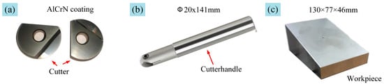
Figure 1.
Experimental materials.

Table 1.
Mechanical properties of YG8 cemented carbide.
Table 2.
Chemical composition of Ti6Al4V.
- 2.
- Coating selection
The AlCrN coating exhibits excellent high-temperature oxidation resistance and corrosion protection properties. Additionally, silicon (Si) demonstrates a tendency to inhibit grain growth, thereby promoting the formation of finer-grained microstructures. Consequently, AlSiTiN and AlCrN were selected for the fabrication of a composite coating on the cemented carbide substrate in this study [19,20]. The composite coating was deposited using cathodic arc ion plating–a physical vapor deposition (PVD) technique. In this process, coating material enters the vapor phase through arc discharge, with the cathode spot stochastically migrating across the target surface. This enables instantaneous target evaporation and highly efficient ionization, which contributes to dense, defect-resistant coatings with superior mechanical properties for cutting tools. The underlying principle is illustrated in Figure 2. Due to its poor electrical conductivity, utilizing AlCrN as the base layer would impede the subsequent deposition of the AlSiTiN coating and result in inadequate adhesion. Therefore, AlSiTiN was deposited first, followed by AlCrN.
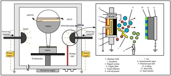
Figure 2.
Preparation platform and mechanism of composite coatings.
This study employed a fabrication sequence involving micro-texturing prior to coating deposition. The resultant composite coating thickness was 3 μm. Both sequences—micro-texturing before coating and coating before micro-texturing—offer distinct advantages. The pre-texturing approach enhances surface performance of the cemented carbide substrate primarily by improving coating-substrate adhesion. Conversely, the post-coating texturing method strengthens the wear resistance of the micro-textures through modification of the coating material properties, thereby also enhancing the substrate’s surface performance.
- 3.
- Micro-texture preparation method
Micro-texture fabrication on the tool surface was performed using a fiber laser, with simultaneous thermal assistance provided by a temperature-controlled heating stage. To mitigate potential non-uniform temperature distribution along the base-to-apex direction of the workpiece—which could lead to heterogeneous microstructures—the workpiece was preheated on the heating stage for 30 min to ensure uniform temperature distribution throughout the specimen prior to processing. The fabrication setup and laser beam morphology are illustrated in Figure 3. The selected fiber laser equipment is Beijing Zhengtian ZT-Q-50 fiber laser (Beijing Zhengtian Hengye CNC Technology Co., Ltd., Beijing, China). The maximum output power is 50 W, the repetition accuracy is ±0.003, the laser wavelength is 1064 nm, the engraving line speed is ≤7000 mm/s, and the repetition frequency is 20–30 kHz.
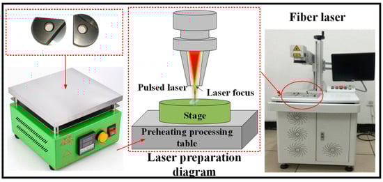
Figure 3.
Thermally assisted laser micro-texture preparation principle diagram.
2.2. Experimental Design
The experimental design employed a Face-Centered Cubic (CCF) configuration within the Central Composite Design (CCD) framework of Response Surface Methodology. This approach represents a relatively simple experimental design that achieves the highest estimation accuracy for interaction term coefficients [21,22], as illustrated in Figure 4. Three variants exist within CCD-based RSM: Circumscribed CCD (axial points outside cube boundaries), Inscribed CCD (axial points within cube boundaries), Face-Centered CCD (axial points on cube faces). The circumscribed CCD permits factor levels beyond cubic boundaries, which both violates operational constraints and increases experimental runs–consequently elevating fabrication costs for micro-textured coated tools. The inscribed CCD sacrifices sequentiality by confining factor levels within a spherical domain, thereby restricting the operational range and compromising subsequent response surface analysis. Conversely, the face-centered CCD positions axial points at cube face centers (α = 1). While this configuration sacrifices rotatability, it effectively reduces complexity from additional design levels and demonstrates superior robustness against experimental error. Notably, it maintains stability even without center points. Given its simplicity and high precision for interaction coefficient estimation, the face-centered CCD was selected. In the six-factor three-level face-centered cubic response surface design, the cubic point part adopts the 2 ^ {6-2} partial factor design (16 points) to reduce the 64 points of the full factor design. The axial point was partially fixed at 2k = 12 points (α = 1). The center point is not added (nc = 0), so the total number of points is 16 + 12 = 28. The micro-texture fabrication parameters and thermal assistance temperature levels are detailed in Table 3 [23].
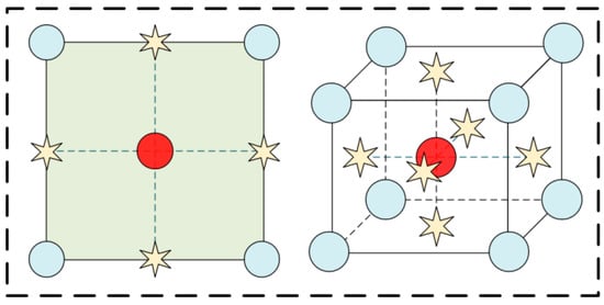
Figure 4.
Design schematic diagram of face-centered cubic response surface method.
Table 3.
Micro-texture preparation parameter table.
2.3. Test Platform Construction
Milling trials of titanium alloy using cemented carbide ball-nose end mills were conducted on a VDL-1000E three-axis vertical milling machine (Dalian Machine Tool Factory, Dalian, China). The machine was instrumented with a Kistler 9257 dynamometer (Kistler, Shanghai, China) to acquire milling forces, complemented by vibration and acoustic emission sensors for comprehensive machining signal acquisition during the milling process. The mounting configuration of the sensors is illustrated in Figure 5. The surface roughness was measured by a surface roughness meter (Beijing Era, Beijing, China). The workpiece was placed on the stage and measured by the instrument. The tool wear was observed by an ultra-depth-of-field microscope (Beijing Pinzhi Chuangsi Precision Instrument Co., Ltd., Beijing, China) and processed by Image-pro plus 6.0. The titanium alloy workpiece was fixtured at an orientation of 15°. The milling parameters employed in the experiments are detailed in Table 4.
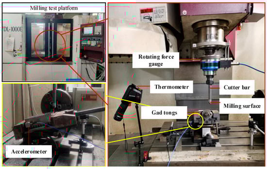
Figure 5.
Milling test platform.
Table 4.
Milling test parameters.
3. The Interaction Mechanism of Texture Preparation Parameters and Thermal Assisted Temperature on Cutting Performance
3.1. Study on the Correlation Between Cutting Performance and Preparation Process Parameters of Textured Coating Tool
Milling force signals acquired during the machining process were processed using DynoWare 2.6.5.16 software. The vector averages of each milling force signal in the three orthogonal directions were first calculated, followed by the determination of the overall mean value throughout the milling cycle. Milling noise signals were measured, and appropriate noise extraction intervals were selected. Time–frequency domain processing and feature extraction of the noise signals were performed using MATLAB 2024, yielding variance eigenvalue data [24,25]. After milling a cumulative length of 15,000 mm, the flank wear of the cutting tool was measured using an ultra-depth-of-field microscope. Similarly, after milling 15,000 mm, the profile roughness of the machined titanium alloy surface was measured using a surface roughness tester. The resultant experimental data are presented in Figure 6.
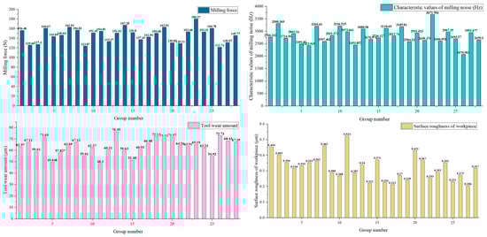
Figure 6.
Milling performance data.
The results of the significance analysis pertaining to the fitting effect of the milling performance model, as presented in Table 5, are derived from the data illustrated in Figure 6.
Table 5.
Milling performance model-fitting effect significance analysis results.
Response surface analysis was performed using Design-Expert software. Based on the quadratic polynomial regression mathematical model of the Central Composite Design Response Surface Methodology, as shown in Equation (1), and considering the milling performance model employed two-factor fitting, the coefficients of the quadratic terms in Equation (1) were set to zero. This resulted in the establishment of a second-order response surface mathematical model incorporating quadratic polynomials and interaction terms for the milling performance of micro-textured cemented carbide tools during titanium alloy machining:
In the formula, yn is the milling performance of cemented carbide tool, x1 is the laser power (W), x2 is the scanning speed (mm/s), x3 is the number of scans, x4 is the micro-texture spacing (μm), x5 is the micro-texture diameter (μm), x6 is the thermal assisted temperature (K). In order to solve the coefficient a, Equation (1) is transformed into matrix form as follows:
In the formula, y is the response variable matrix; X represent the selected experimental data, a is the coefficient vector in the process of model construction, m and n represent the number of rows and columns of the experimental design matrix, respectively.
Then, the least squares algorithm is used to solve Equation (2) which will make the model produce the smallest residual error as far as possible. Equation (2) is mathematically transformed, and the coefficient a is calculated by Equation (3).
By setting the quadratic coefficients to 0, substituting the milling force into Equation (3), and solving the resulting equation, the solution for b was obtained. Subsequently, substituting b into Equation (1) yielded the two-factor response surface model for the performance mean, represented by Equation (4). Here, y1, y2, y3, and y4 denote the milling force, milling noise, tool wear, and workpiece surface roughness, respectively.
Analysis of variance (ANOVA) was performed on the second-order response surface model for milling performance. The results, as presented in Table 6, demonstrate that the overall regression model is highly significant. The correlation coefficient of the fitted model approaches unity, indicating excellent goodness-of-fit and high model reliability. Consequently, the model can be reliably employed for predicting the milling noise characteristic values during titanium alloy milling using micro-textured coated carbide tools.
Table 6.
Correlation analysis results of milling force model factors.
Analysis of the p for coefficients in each milling performance model identified the most influential factors. The relative significance of individual factors, determined via F, established their hierarchical impact order. Subsequent response surface analysis focused on higher-order interactions involving thermal assistance temperature.
For Milling Force: Scanning speed, number of scans, and micro-texture diameter exhibited p < 0.05, indicating significant effects. F ranking: Number of scans > Scanning speed > Micro-texture diameter > Micro-texture spacing > Laser power > Thermal assistance temperature. Significant interactions: Scanning speed × Thermal temp, Number of scans × Thermal temp, Micro-texture diameter × Thermal temp.
For Milling Noise: All single factors showed p < 0.05, confirming universal influence on noise variation. F ranking: Thermal temp > Micro-texture diameter > Laser power > Micro-texture spacing > Scanning speed > Number of scans. Significant interactions: Micro-texture spacing × Thermal temp, Micro-texture diameter × Thermal temp.
For Tool Wear: Laser power, scanning speed, number of scans, and thermal temperature demonstrated p < 0.05. F ranking: Laser power > Scanning speed > Thermal temp > Number of scans > Micro-texture spacing > Micro-texture diameter. Significant interactions: Scanning speed × Thermal temp, Number of scans × Thermal temp.
For Workpiece Surface Roughness: Scanning speed, micro-texture diameter, and thermal temperature showed p < 0.05. F ranking: Scanning speed > Thermal temp > Micro-texture diameter > Number of scans > Micro-texture spacing > Laser power. Significant interactions: Number of scans × Thermal temp, Micro-texture diameter × Thermal temp.
3.2. Analysis of the Influence of the Interaction Beween Texture Preparation Parameters and Thermal Assisted Temperature on Milling Performance
Figure 7 illustrates the interaction effect between thermal assistance temperature and scanning speed on milling force. As observed from the figure, scanning speed exerts a marked influence on milling force when thermal assistance temperature is elevated. Increased thermal assistance temperature enhances the laser absorption rate of the cemented carbide tool surface. This phenomenon eliminates the need to prolong scanning duration or reduce scanning speed for improved micro-texture fabrication efficacy. Consequently, the efficiency of micro-texture fabrication is enhanced.
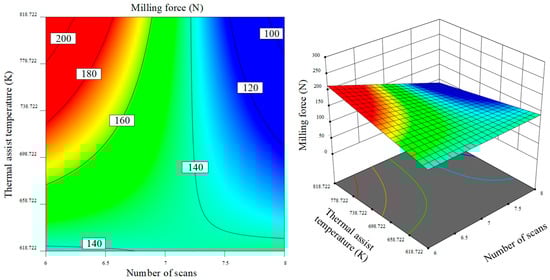
Figure 7.
Interaction between scanning speed and thermal assisted temperature on milling force.
As shown in Figure 8, the interaction between the thermal assisted temperature and the number of scans on the milling force is shown. It can be seen from the figure that as the thermal assisted temperature increases, the influence of the scanning speed on the milling force increases. In the case of high thermal auxiliary temperature, the increase of scanning times increases the heat-affected zone around the texture, reduces the heat generated in the milling process, and improves the wear resistance of the rake face of the tool. Figure 9 shows the interaction between the thermal assisted temperature and the micro-texture diameter on the milling force. It can be seen from the figure that the micro-texture diameter has a great influence on the milling force when the thermal assisted temperature is low. This is because when the heat-assisted temperature is low, the heat-affected zone around the texture decreases, and the fluctuation of the micro-texture diameter is larger than that of the heat-affected zone. When the diameter of the micro-texture is small, the energy is more concentrated into the rake face of the tool. The accumulation and difficult diffusion of heat lead to the increase of the radial depth of the micro-texture and the improvement of the chip storage capacity of the micro-texture, as shown in Figure 10. From the perspective of the bending degree of the graph, the interaction between the number of scans and the heat-assisted temperature has the smallest effect on the milling force in the two types of interactions.
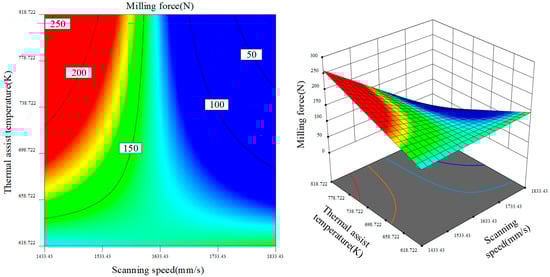
Figure 8.
Interaction between scanning times and thermally assisted temperature on milling force.
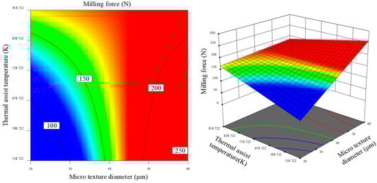
Figure 9.
Interaction between micro-texture diameter and thermally assisted temperature on milling force.
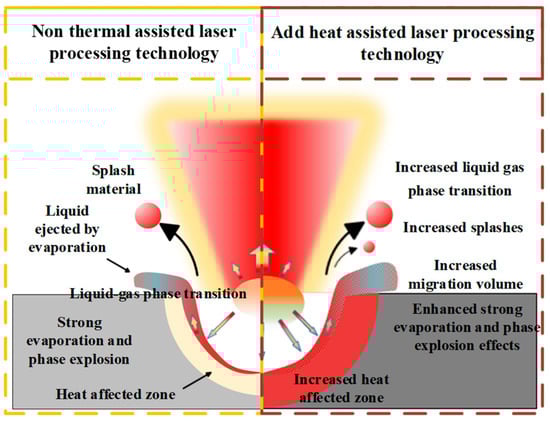
Figure 10.
Heat assistance can accumulate heat and improve chip storage capacity.
Figure 11 and Figure 12 present the response surfaces depicting the effects of thermal assistance temperature versus micro-texture spacing and micro-texture diameter, respectively. It is evident that lower thermal assistance temperatures combined with larger micro-texture spacing and smaller micro-texture diameters yield reduced milling noise. This phenomenon occurs because insufficient energy absorption by the workpiece under these conditions results in accelerated cooling rates after micro-texture fabrication on the cemented carbide substrate. The rapid cooling promotes grain refinement, while the lower thermal assistance temperature effectively suppresses crack formation within the micro-texture dimples, as corroborated in Figure 13.
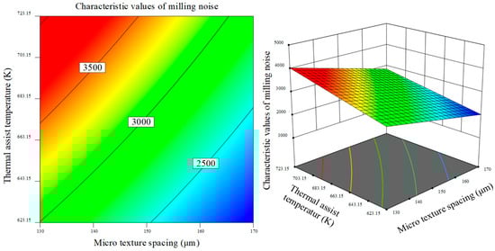
Figure 11.
Interaction between micro-texture spacing and thermal assisted temperature on milling noise characteristic value.
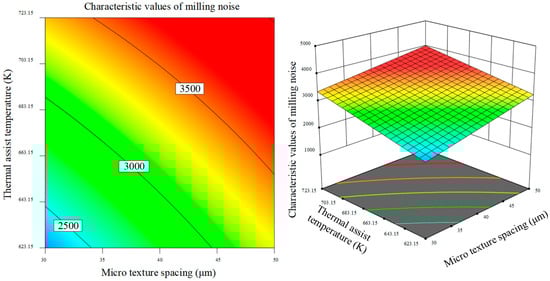
Figure 12.
Interaction between micro-texture diameter and thermal assisted temperature on the characteristic value of milling noise.
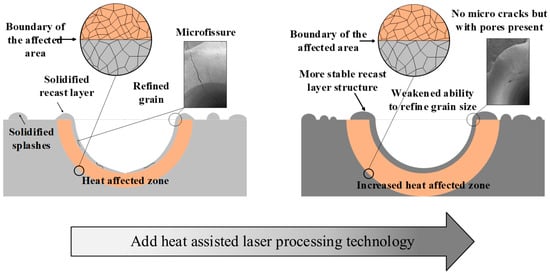
Figure 13.
Heat-assisted suppression of cracks in pits to refine grains.
Excessive thermal assistance temperatures and energy inputs induce increased porosity within the material. This porosity promotes stress concentration, thereby diminishing material strength and compromising the structural stability of micro-textures. Consequently, machining efficacy deteriorates while milling noise intensifies. Simultaneously, the expanded heat-affected zone adversely affects the structural integrity and functional performance of the tool’s rake face. Further propagation of thermal effects to the cutting edge region reduces edge toughness, ultimately impairing overall milling performance.
As evidenced in Figure 14 and Figure 15, examining the interaction between micro-texture fabrication parameters and thermal assistance temperature on tool wear reveals a consistent positive correlation: higher thermal assistance temperatures invariably correspond to increased tool wear. This relationship stems from enhanced laser energy absorption by the substrate at elevated temperatures. Notably, under conditions of low scanning speed or high scanning frequency combined with moderate thermal assistance temperatures, the heat-affected zone distribution surrounding surface textures demonstrates optimal characteristics. This configuration yields superior surface hardness, wear resistance, fracture toughness, and impact resistance collectively enhancing the anti-wear performance of micro-textured coated surfaces.
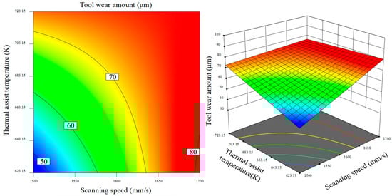
Figure 14.
The interaction between scanning speed and thermal assisted temperature on tool wear.
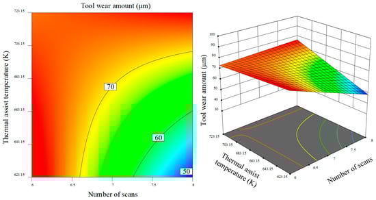
Figure 15.
The interaction between the number of scans and the heat-assisted temperature on the tool wear.
Figure 16 and Figure 17 jointly demonstrate an inverse proportionality between thermal assistance temperature and workpiece surface roughness across the examined interactions of micro-texture fabrication parameters and thermal conditions: higher thermal assistance temperatures consistently correspond to reduced surface roughness. Figure 16 reveals that under low thermal assistance temperatures coupled with minimal scanning frequencies, micro-textured coated tools yield suboptimal milling outcomes. Concurrently, diminished scanning frequencies increase the sensitivity of surface roughness to thermal assistance temperature variations. Peak sensitivity occurs at a scanning frequency of 6, where thermal assistance temperature exerts the greatest influence on surface roughness modulation.
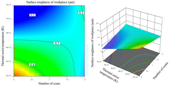
Figure 16.
The interaction between scanning times and heat-assisted temperature on the surface roughness of workpiece.
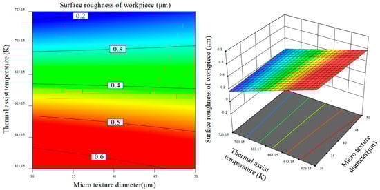
Figure 17.
Interaction of micro-texture diameter and heat-assisted temperature on surface roughness of workpiece.
As demonstrated in Figure 17, smaller micro-texture diameters consistently yield reduced workpiece surface roughness regardless of thermal assistance temperature variations. This phenomenon arises from concentrated laser energy within smaller dimples, which enhances penetration depth and amplifies debris accommodation capacity. Consequently, workpiece surface scoring by cutting debris is effectively mitigated, thereby lowering surface roughness as a beneficial byproduct.
4. Multi-Objective Optimization of Textured Coating Tool Preparation Process Parameters Based on Response Surface Method
This section will optimize the combination of micro-texture preparation parameters according to the regression model in the first four sections, and optimize the four response variables of milling force, milling noise, tool wear and workpiece surface roughness of the textured coating tool. The purpose is to find a set of parameters, so that the milling performance of the textured coating tool is optimal, and the response variables are limited. The limit range of milling force is (121.74–180.27), the limit range of milling noise eigenvalue is (2070.9–3671.5), and the limit range of tool wear is (48.3–76.45). The boundary range of the surface roughness of the workpiece is (0.206–0.524), and the importance of the response variable is divided. The change of the surface roughness of the workpiece and the wear of the tool is the third level of importance, the change of the milling force is the second level of importance, and the change of the characteristic value of the milling noise is the first level of importance. Some of the preparation parameters need to select the integers close to the optimal parameters. After, the relevant settings are completed, as shown in Figure 18.
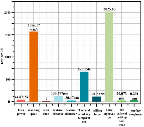
Figure 18.
Multi-objective optimization results.
Compared to the response variable ranges established earlier, the predicted value ranges obtained via design expert analysis were (104.128–138.537) for milling force, (1749.57–2301.73) for milling noise characteristic value, (16.1769–41.9691) for tool wear, and (0.08208–0.320786) for workpiece surface roughness. Deviations between the experimental and predicted values were confined within 5%, validating the authenticity and reliability of the optimized results. Verification experiments were conducted on the titanium alloy milling platform described in Section 2.3 using micro-textured coated ball-nose milling tools fabricated with optimal parameters. The measured results—milling force: 121.849 N, milling noise characteristic value: 1923.945, tool wear: 35.64 μm, and workpiece surface roughness: 0.255 μm—demonstrated excellent agreement with predictions, thereby conclusively validating the reliability of the multi-objective milling performance prediction model.
5. Conclusions
This paper systematically investigates the influence of heat-assisted temperature on the surface micro-texture performance and milling effects of cemented carbide tools, yielding the following key conclusions:
At lower heat-assisted temperatures, the heat-affected zone around the micro-textures is smaller, resulting in more concentrated energy input. The smaller diameter of the micro-textures promotes the accumulation and concentration of energy on the cutting face, limiting its diffusion and effectively increasing the radial depth of the micro-textures. This significantly enhances the chip retention capability. Under lower heat-assisted temperatures, a combination of large micro-texture spacing and small micro-texture diameter effectively reduces milling noise. This is attributed to the lower total energy absorbed by the substrate, which shortens the cooling time required after micro-texture preparation and further benefits the grain refinement process. The lower heat-assisted temperature is also effective in suppressing crack formation within the micro-texture pits, ensuring the structural integrity of the micro-textures.
Excessively high heat-assisted temperatures and the accompanying energy input lead to an increase in porosity within the micro-texture region, resulting in stress concentration that weakens material strength and ultimately damages the structural stability of the micro-textures. This not only adversely affects the milling performance, significantly increasing milling noise, but also expands the heat-affected zone, impacting the structural performance of the cutting face and even extending to the cutting edge. This weakens the toughness of the cutting edge, further deteriorating the milling performance. The study confirms a positive correlation between heat-assisted temperature and tool wear, with an increase in temperature leading to a higher absorption rate of laser energy by the substrate, thereby accelerating tool wear.
Under conditions of low scanning speed or multiple scanning passes, a lower heat-assisted temperature can achieve a reasonable distribution of the heat-affected zone around the micro-textured surface. This optimized thermal state helps maintain and enhance the hardness, wear resistance, toughness, and impact resistance of the tool surface, ultimately resulting in improved wear resistance of the textured coating surface.
By integrating heat-assisted laser material processing into micro-texture preparation technology, this approach effectively addresses issues such as high cutting force, rapid tool wear, and low surface roughness in the milling of titanium alloys with textured coating tools. This method is of great significance for achieving high-precision, high-quality machining of difficult-to-process materials, such as titanium alloys.
Author Contributions
Conceptualization, X.L. and X.T.; methodology, X.W.; validation, X.W., X.T.; formal analysis, X.T.; investigation, X.L. and B.W.; resources, X.W.; writing—original draft preparation, X.T.; writing—review and editing, X.L. and B.W.; funding acquisition, X.L. and X.W. All authors have read and agreed to the published version of the manuscript.
Funding
This research was funded by the Natural Science Foundation of Heilongjiang, grant no. LH2024E083.
Institutional Review Board Statement
Not applicable.
Informed Consent Statement
Not applicable.
Data Availability Statement
Data is contained within the article.
Conflicts of Interest
The authors declare no conflicts of interest.
References
- Obikawa, T.; Kamio, A.; Takaoka, H.; Osada, A. Micro-texture at the coated tool face for high performance cutting. Int. J. Mach. Tools Manuf. 2011, 51, 966–972. [Google Scholar] [CrossRef]
- Xiao, B.; Zhang, T.F.; Guo, Z.; Li, Z.; Fan, B.; Chen, G.; Xiong, Z.; Wang, Q. Mechanical, oxidation, and cutting properties of AlCrN/AlTiSiN nano-multilayer coatings. Surf. Coat. Technol. 2022, 433, 128094. [Google Scholar] [CrossRef]
- Yu, Y.; Yang, F.Z.; Jiang, F.L.; Huang, K.; Liu, C.W. Research progress of laser processing micro-texture and its functional analysis in improving tribological properties. Tool Technol. 2023, 57, 3–12. [Google Scholar] [CrossRef]
- Xuan, W.T.; Chen, G.J.; Wang, J.X.; Zhao, L.X.; Jia, X.F. Surface micro-textured tool cutting technology. Tool Technol. 2023, 57, 3–14. [Google Scholar]
- Li, J.P. Preparation and Properties of 7075/6061 Aluminum Alloy Bimetallic Composites. Ph.D. Thesis, Jiangsu University, Zhenjiang, China, 2022. [Google Scholar]
- Yu, W.H.; Sing, S.L.; Chua, C.K.; Kuo, C.N.; Tian, X.L. Particle-Reinforced Metal Matrix Nanocomposites Fabricated by Selective Laser Melting: A State of the Art Review. Prog. Mater. Sci. 2019, 104, 330–379. [Google Scholar] [CrossRef]
- Wang, D.L.; Zhang, J.L.; Yi, X.B. Effect of cutting speed on cutting performance of micro-textured coated tools. Mod. Manuf. Eng. 2023, 159, 106–111. [Google Scholar]
- Jiang, Y.; Wang, D.Z.; Mao, W. Research on the Mechanism of Cutting AISI1045 with Al2O3 TiC Coating Micro textured Cutting Tools. Agric. Equip. Veh. Eng. 2023, 61, 137–140. [Google Scholar] [CrossRef]
- Liu, X.; Liu, Y.; Li, L.; Tian, Y. Performances of micro-textured WC-10Ni3Al cemented carbides cutting tool in turning of Ti6Al4V. Int. J. Refract. Met. Hard Mater. 2019, 84, 104987. [Google Scholar] [CrossRef]
- Li, Q.; Ma, C.; Xie, L.; Wang, B.; Zhang, S. Effect of Coated Composite Micro–Texture Tool on Cutting Shape and Cutting Force during Aluminum Alloy Cutting. Machines 2023, 11, 439. [Google Scholar] [CrossRef]
- Yang, H.; Yang, S.; Tong, X. Study on the Matching of Surface Texture Parameters and Processing Parameters of Coated Cemented Carbide Tools. Coatings 2023, 13, 681. [Google Scholar] [CrossRef]
- Wang, J.; Liu, Z.; Wu, Y.; Wang, Q.; Shu, D. Cutting Performance and Tool Wear of AlCrN- and TiAlN-Coated Carbide Tools during Milling of Tantalum–Tungsten Alloy. Machines 2024, 12, 170. [Google Scholar] [CrossRef]
- Timata, M.; Saikaew, C. Experimental and Simulation Study on Tool Life Models in Drilling of Forging Brass Using Uncoated-WC and AlCrN Coated-WC Tools. Coatings 2019, 9, 853. [Google Scholar] [CrossRef]
- Liang, F.L.; Li, K.Y.; Shi, W.Q.; Zhu, Z.K.; He, Q.L. Effect of CeO2 addition on laser cladding Ni-based/WC composite coatings. Laser Technol. 2024, 48, 542–548. [Google Scholar] [CrossRef]
- Guo, C.H.; Li, C.W.; Yang, H.; Du, S.M.; Liu, E.Y. Effect of preheating on microstructure and mechanical properties of laser cladding heat affected zone of 27SiMn steel. Min. Metall. Eng. 2023, 43, 145–149. [Google Scholar] [CrossRef]
- Yang, W.B.; Li, S.Y.; Xiao, Q.; Chen, D.Y.; Zhang, B.; Xia, J.L.; Wang, S. Effect of substrate preheating on microstructure and properties of laser cladding layer of cobalt-based alloy. Hot Work. Process 2023, 52, 97–107. [Google Scholar] [CrossRef]
- Kuntoğlu, M.; Salur, E.; Canli, E.; Aslan, A.; Gupta, M.K.; Waqar, S.; Krolczyk, G.M.; Xu, J. A state of the art on surface morphology of selective laser-melted metallic alloys. Int. J. Adv. Manuf. Technol. 2023, 127, 1103–1142. [Google Scholar] [CrossRef]
- Lajis, M.A.; Nurul Amin, A.K.M.; Karim, A.M.; Hafiz, A.M.K. Preheating in End Milling of AISI D2 Hardened Steel with Coated Carbide Inserts. In Advanced Materials Research; Trans Tech Publications, Ltd.: Bäch, Switzerland, 2009; Volume 83. [Google Scholar] [CrossRef]
- Geyao, L.; Yang, D.; Wanglin, C.; Chengyong, W. Development and application of physical vapor deposited coatings for medical devices: A review. Procedia CIRP 2020, 89, 250–262. [Google Scholar] [CrossRef]
- Yang, S.; Yu, D.; Wang, D. Effect of Surface-Textured AlSiTiN Coating Parameters on the Performance of Ball-End Milling Cutter in Titanium Alloy Milling. Coatings 2024, 14, 1458. [Google Scholar] [CrossRef]
- Xu, L.J.; Zhou, H.A.; Pu, Y.Z.; Meng, J.B.; Dong, X.J.; Li, H.M.; Yu, H.Y. Optimization of process parameters for MQL-assisted cutting of titanium alloy based on response surface method. Mach. Hydraul. 2023, 51, 13–18. [Google Scholar]
- Phokobye, S.N.; Desai, D.A.; Tlhabadira, I.; Sadiku, E.R.; Mutombo, K. Comparative investigation and optimization of cutting tools performance during milling machining of titanium alloy (Ti6Al4V) using response surface methodology. Int. J. Adv. Manuf. Technol. 2024, 131, 3565–3577. [Google Scholar] [CrossRef]
- Liu, Z.P.; Gu, J.; Wang, J.C.; Zhang, J.S.; Yu, L.B. Research on Laser Cladding Process of WC Co Hard Alloy Coating. Appl. Laser 2021, 41, 715–723. [Google Scholar] [CrossRef]
- Wang, S.; Tong, X.; Yang, S.; Han, P. Analysis of friction and wear vibration signals in Micro-Textured coated Cemented Carbide and Titanium Alloys using the STFT-CWT method. Mech. Syst. Signal Process. 2025, 224, 112237. [Google Scholar] [CrossRef]
- Tong, X.; Wang, S. Effect of laser texturing process on properties of composite coated cemented carbide ball-end milling cutter milling titanium alloy. Proc. Inst. Mech. Eng. Part B J. Eng. Manuf. 2025, 239, 146–161. [Google Scholar] [CrossRef]
Disclaimer/Publisher’s Note: The statements, opinions and data contained in all publications are solely those of the individual author(s) and contributor(s) and not of MDPI and/or the editor(s). MDPI and/or the editor(s) disclaim responsibility for any injury to people or property resulting from any ideas, methods, instructions or products referred to in the content. |
© 2025 by the authors. Licensee MDPI, Basel, Switzerland. This article is an open access article distributed under the terms and conditions of the Creative Commons Attribution (CC BY) license (https://creativecommons.org/licenses/by/4.0/).