Review

Research Progress on Tunable External Cavity Semiconductor Lasers in Visible and Near-Infrared Wavebands

1
College of Physics and Electronic Engineering, Hainan Normal University, Haikou 571158, China
2
Hainan Provincial Key Laboratory of Laser Technology and Optoelectronic Functional Materials, Haikou 571158, China
3
Hainan International Joint Research Center for Semiconductor Lasers, Hainan Normal University, Haikou 571158, China
4
Academician Team Innovation Center of Hainan Province, Haikou 571158, China
*
Author to whom correspondence should be addressed.
Coatings 2025, 15(9), 1010; https://doi.org/10.3390/coatings15091010
Submission received: 17 July 2025 / Revised: 18 August 2025 / Accepted: 29 August 2025 / Published: 1 September 2025
(This article belongs to the Special Issue Research in Laser Welding and Surface Treatment Technology)

Abstract

The TECSL has attracted much attention due to its wide tuning range, narrow linewidth, high output power, and excellent SMSR. It holds irreplaceable value in optical communication, spectroscopy analysis, and biomedical applications. The demand for a wide tuning range, high power, narrow linewidth, and a high SMSR has driven the development of high-performance TECSL structures. This paper comprehensively discusses five key TECSL structures: Littrow-type structures, Littman-type structures, filter-type structures, fiber-type structures, and waveguide-type structures, and elaborates on their structures and principles. This paper reviews the research process of different type-structure TECSLs, analyzes the advantages and disadvantages of different external cavity structures, and explores the future development trends of TECSLs. The review shows that the Littrow-type structure TECSL achieved an extremely wide tuning range using diffraction gratings, reaching up to 360 nm. The Littman-type structure TECSL demonstrated excellent spectral purity, achieving an SMSR of 71.03 dB. The filter-type structure TECSL was able to achieve flexible wavelength selection using tunable filters, achieving a linewidth of 570 Hz. The fiber-type structure TECSL has a linewidth of up to 600 Hz. The waveguide-type structure TECSL can achieve a linewidth as low as 0.252 kHz and a tuning range of up to 120.9 nm.

1. Introduction

In 1970, Corning Inc. of the United States turned the fiber theory proposed by Charles Kao into reality and successfully produced the world’s first fiber, thus entering the era of optical communication. Since then, the main laser in optical communication—semiconductor lasers—have also developed rapidly. The direct bandgap semiconductor materials of the III-V group, such as GaAs, InP, and GaN, have been widely used in semiconductor lasers due to their high quantum efficiency, and semiconductor lasers with various characteristics, such as high power, narrow linewidth, and tunable wavelength, have also been developed [1,2]. Among them, the tunable external cavity semiconductor laser (TECSL) has been widely applied in spectral analysis, environmental monitoring, and quantum technology in photonics due to its advantages such as compact structure, high efficiency, long life span, excellent spectral characteristics, and tunable wavelength [3]. In the field of optical communication, especially in fiber communication and sensor networks, emerging industries, such as the Internet of Things (IoT) and smart cities, have continuously increasing demands for high-speed communication, and the demand for multi-wavelength lasers is also becoming more and more urgent, thereby promoting the development of TECSLs. In the field of gas detection, the TECSL can be used as a laser for gas detection, generating high-resolution gas characteristic absorption spectra, thereby improving the sensitivity of the gas detection system. To meet the requirements of high-speed and large-capacity communication, dense wavelength division multiplexing (DWDM) is one of the most effective technologies in current core and optical access networks. The TECSL is also a crucial laser device in DWDM systems [4]. Due to the lack of frequency sources, the demand for TECSLs in ultra-DWDM systems will continue to increase. Therefore, the TECSL has significant application value in areas such as optical communication, gas detection, and DWDM technology. Moreover, the TECSL is also widely used in fields such as biomedicine and imaging, quantum communication, and precise measurement.
This paper introduces five important types of TECSLs: Littrow-type structures, Littman-type structures, filter-type structures, fiber-type structures, and waveguide-type structures. This paper reviews the research progress of TECSLs, introduces the structures and principles of the Littrow-type structure TECSL, the Littman-type structure TECSL, the filter-type structure TECSL, the fiber-type structure TECSL, and the waveguide-type structure TECSL, and finally analyzes the advantages and disadvantages of different external cavity types and introduces the development trend and application prospects of TECSLs.

2. Littrow-Type Structure TECSLs

2.1. The Structure and Principle of the Littrow-Type Structure TECSL

The Littrow-type structure TECSL is a grating-based TECSL. It is usually tuned by a micro-electro-mechanical system (MEMS). The Littrow-type structure TECSL is tuned by rotating the grating [1,2,5]. The grating-type structure TECSL uses a grating as the external cavity mode selection device to achieve wavelength tuning and linewidth narrowing. A diffraction grating is composed of a medium with a periodically varying thickness and a constant refractive index, or a medium with a periodically varying refractive index and a constant thickness. Its wavelength selectivity can be expressed by the diffraction Formula (1) as follows:
  m λ = d sin θ i + sin θ d
where λ is the output wavelength, m is the diffraction order, d is the diffraction grating constant, and θ i and θ d are the incident angle and diffraction angle, respectively. Commonly used diffraction gratings include different types such as reflection gratings, transmission gratings, and diffraction gratings.
Figure 1 shows the basic structure of the Littrow-type structure TECSL, which is generally composed of a laser diode (LD) gain chip, a collimating lens, and a diffraction grating. The grating in the external resonant cavity is the main mode selection element, which has the functions of wavelength tuning and linewidth narrowing.
The beam generated by the gain chip is collimated by the collimating lens and then incident on the diffraction grating. After diffraction by the grating, the first-order diffracted laser returns along the original optical path to the active region of the laser, reducing the laser loss at a specific wavelength and enabling it to reach the lasing threshold preferentially. This locks the working wavelength of the laser at a specific wavelength, resulting in the laser being output from the zero-order diffraction direction of the grating or the rear end face of the chip.
For a collimating lens, it needs to meet several key requirements to achieve efficient optical coupling and stable beam control. Firstly, the collimating lens must have a high numerical aperture to enhance the light collection efficiency. Secondly, a short focal length design helps to reduce the size of the light spot and needs to be optimized in combination with the fast and slow axis divergence angles of the laser diode. Finally, the transmittance of the collimating lens in the working wavelength range should exceed 99%, and the numerical aperture of the collimating lens should be compatible with the diffraction angle of the grating. According to the laser emission direction, the Littrow-type structure TECSL can be further classified into the Type-A structure and Type-B structure, as shown in Figure 1.
In Type-A Littrow TECSL configurations, the gain chip typically features a high-reflection (HR) coating on one facet and an anti-reflection (AR) coating on the opposite facet. This design predominantly employs the zero-order diffraction output from the grating. Through integration with precision actuators, optimal angular adjustment of the bulk grating is achieved, enabling both wavelength tuning and multi-directional laser output capabilities.
Its drawback lies in that when adjusting the grating angle for wavelength selection, the direction of the output laser will also change accordingly, which is not conducive to practical applications. By further altering the structure to make the laser output from the rear end face of the diode [6], this problem was effectively solved, and its structure is shown in Figure 1b. At present, most of the research schemes of the Littrow-type structure TECSL are based on the improved Type-B Littrow structure.
In the Type-B Littrow TECSL configuration, the gain chip typically employs anti-reflection AR coatings on both facets. The first-order diffracted laser from the grating is selectively fed back into the active region of the gain chip, where the dominant single longitudinal mode emerges through mode competition and is subsequently output via the rear facet of the Type-B structure. Although the Type-B Littrow TECSL overcomes several limitations inherent to its Type-A counterpart, its implementation requires additional optical components, consequently introducing higher insertion losses and more complex optomechanical alignment challenges.
For the Littrow-type structure TECSL, the lasing wavelength is determined by the standing waves formed in the cavity. The nodes of the standing waves are located in the grating grooves. Therefore, the lasing wavelength is mainly determined by the grating and the cavity length. The output wavelength of the laser can be tuned by changing the position and angle of the grating to alter the first-order diffraction angle.
According to the resonant mode formula of the resonant cavity (2) and the minimum loss wavelength formula of the grating (3), the lasing wavelength that meets the conditions can be obtained [7] as follows:
L = q λ q 2
λ = 2 dsin θ d
where L is the effective cavity length, q is a positive integer, and λ q is the resonant cavity mode wavelength. Rotate the grating angle to change the first-order diffraction angle θ d , thereby adjusting the lasing wavelength of the resonant cavity to achieve the function of wavelength tuning. Under ideal conditions, the wavelength tuning range of the Littrow-type structure TECSL is approximately the gain spectral width of the laser chip. The linewidth formula of the grating external cavity laser (4) [8] is as follows:
Δ ν = Δ v 0 1 + α 2 cos 2 φ R 2 1 R 2 2 R d n l L 2
where Δ ν is the linewidth of the external cavity laser, Δ v 0 is the linewidth of the gain chip, α is the linewidth broadening factor, c o s φ is the phase matching factor, R 2 is the reflectance of the rear end face of the laser resonant cavity, R d is the first-order diffraction efficiency of the grating, n is a positive integer, and l is the length of the inner cavity of the laser. The phase matching factor is a parameter that describes the phase matching efficiency in nonlinear optical processes. It is used to measure the degree of phase relationship matching of the laser involved in the interaction during its propagation. Constructing an external resonant cavity with a grating can greatly increase the effective cavity length of the laser resonant cavity. Introducing the grating end face is equivalent to increasing the end face reflectivity of the resonant cavity, reducing the threshold gain, which is conducive to increasing stimulated emission and suppressing spontaneous emission, thereby narrowing the linewidth of the laser.
For the Littrow structure, either a diffraction grating or a holographic grating can be used. Generally, the first-order diffraction efficiency of its reflection coefficient is greater than 90%, the main loss is the first-order loss, the line count is 600–1800 lines/mm, and the most common one is 1200 lines/mm.
The semiconductor crystal design must meet a series of strict technical requirements to achieve high-performance laser output. In the design of stripe-type laser diodes, the stripe width is typically controlled within the range of 5–20 μm to effectively suppress higher-order transverse modes and maintain single transverse mode output. The optimization of the mirror reflection coefficient is crucial. The front cavity surface is usually coated with an AR coating, with the reflection rate controlled at 5%–30% to balance the output power and external feedback requirements; the rear cavity surface needs to achieve a high reflection rate (HR coating) of more than 90%, thereby significantly reducing the threshold current.

2.2. Research Progress of the Littrow-Type Structure TECSL

As early as the 1960s, it was proposed to use the Littrow structure for wavelength selection of a multi-wavelength laser [9] and to explore how to achieve a scheme that ensures the output laser direction remains unchanged when different wavelengths are selected.
In 2006, Loh et al. [10] conducted an experimental study on the influence of key parameters in the Littrow-type structure TECSL on the output spectral linewidth. In the continuous mode, the results showed that the grating line density had a significant impact on the output spectral linewidth of the tunable laser. The linewidth is influenced by the reflectivity and resolution of the grating. The higher the reflectivity and resolution, the narrower the linewidth. The influence of grating resolution on the linewidth is greater than that of grating reflectivity. The typical linewidth of lasers operating around 399 nm, 780 nm, and 852 nm is 250–600 kHz.
In 2016, Chi et al. [11] discovered a laser system based on a high-power GaN diode laser and adopted the Littrow external cavity structure. Both a holographic diffraction grating and a ruled diffraction grating are used as feedback elements in the external cavity. In the continuous mode, when using the holographic grating, the laser system can be adjusted within a range of 1.4 nm, with an output power of approximately 530 mW; when using the ruled grating, the laser system can be adjusted within a range of 6.0 nm, with an output power of approximately 80 mW.
In 2018, Guo et al. [12] proposed a Littrow-type structure TECSL realization with a wide range of mode-hopping-free and output beam direction invariant features. In the continuous mode, the experimental results show that when the initial external cavity length is 12.82 mm, a continuous tunable laser output without mode hopping of 4.34 nm can be realized in the 805 nm band.
In 2019, Chen et al. [13] reported that a 445 nm blue InGaN semiconductor laser with a conventional Littrow structure achieved wavelength tuning over 4 nm by adjusting the grating position with Piezoelectric Ceramics (PZTs). In the continuous mode, the laser output with a maximum output power of 20 mW and a linewidth of 4.7 MHz.
In 2020, Kapasi et al. [14] reported a 2 µm band narrow-linewidth tunable laser for gravitational wave detection. The Littrow-type structure TECSL is composed of commercial saturable absorber feedback (SAF) gain chips and diffraction gratings. The grating is controlled by PZTs, and the linewidth reaches 20 kHz within an integration time of 10 ms. In the pulsed mode, when the injection current is 400 mA, the available laser output power exceeds 9 mW. The output power can reach 15 mW under the large current of the diode, and the wavelength tuning range is 120 nm. The measured optical power exiting the fiber after the isolator is presented in Figure 2a as a function of injection current. Figure 2b shows the fine-tuning wavelength range when the injection current is 400 mA. The full width at half maximum (FWHM) tuning range is 120 nm.
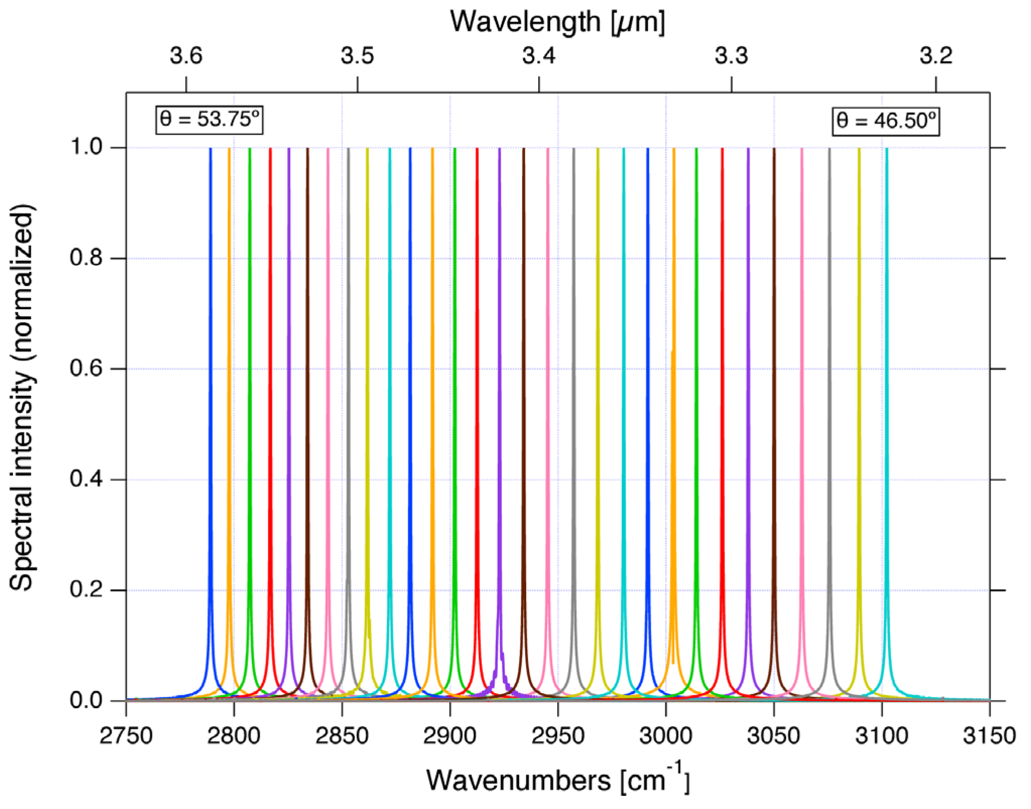
In 2021, Giraud et al. [15] reported an external cavity interband cascade broadband tunable laser based on the Littrow structure operating at room temperature, achieving a wide-range continuous tunable output of 360 nm, tuned from 3.22 μm to 3.58 μm. In the continuous mode, when the injection current is 192 mA, the maximum output power can reach 13 mW, and the side mode suppression ratio (SMSR) is better than 35 dB. Measured emission spectra in continuous wave operation at room temperature (293 K) are shown in Figure 3.
In 2024, Zhao et al. [16] proposed a structure featuring a 100 μm strip broad-area laser with a 780 nm narrow linewidth and a wide tuning range, based on Littrow-type transmission gratings. Compared with volumetric Bragg gratings (VBGs), this structure has a narrower linewidth, and the central wavelength of the diode laser has been locked without thermal drift. High-power 780 nm narrow-linewidth broad-area diode lasers are of great concern in the development of rubidium diode-pumped alkali lasers (DPALs). The VBG plays a crucial role in DPAL engineering due to its high efficiency and the simplicity of spectral narrowing. However, due to the inherent absorption of photo-thermal refractive glass, there will be a natural wavelength drift, which is caused by the temperature rise of VBGs. In the early stages of DPAL development, Littrow or Littman reflective grating external cavities were widely used for spectral narrowing of high-power laser diode arrays. However, all these methods based on reflective gratings faced the problem of folding optical devices. In recent years, the transmission grating technology has been greatly improved, providing the possibility to reconsider its application in high-power, wide-area diode lasers. Compared with DPAL using VBGs, methods based on reflective gratings do not cause thermal drift and are more stable. By carefully focusing the diode laser beam, results with a linewidth less than 0.17 nm and an SMSR over 20 dB were achieved. In the continuous mode, when the driving current is 7 A, the output power can reach 3.05 W, with a tuning range of 773.5 nm to 782.5 nm.
In 2025, Hu et al. [17] designed a high-resolution mode measurement system to study the mode after coupling a blue semiconductor laser tube with a dual grating external cavity in the Littrow configuration. When in continuous mode and with an injection current of 400 mA, its peak wavelength was adjusted to 8.6 nm (439.4 nm to 448 nm), thereby compressing the spectral width to approximately 30 pm, and the maximum power was 36 mW at this time.
Table 1 shows the development of Littrow-type structure TECSLs. Kapasi et al. [14] utilized commercial SAF gain chips and PZT-controlled diffraction gratings to achieve a breakthrough in output performance in the 2 μm wavelength range. This innovative configuration simultaneously achieved an ultra-narrow linewidth of 20 kHz and an extremely wide tuning range of 120 nm. The combination of this narrow linewidth and wide tuning range characteristic makes it particularly suitable for quantum optical experiments and coherent optical communication. Giraud et al. [15] combined the Littrow-type structure TECSL with interband cascade gain media and achieved 360 nm ultra-wideband continuous tuning output. This breakthrough makes it applicable to gas molecule detection and other applications. Zhao et al. [16] studied the Littrow-type TECSL whose central wavelength was locked and did not have thermal drift phenomena. This structure could output 3.05 W of power at a 7 A driving current. This design has watt-level output power and excellent thermal stability and is suitable for high-power applications that require precise wavelength control. The blue laser of Hu et al. [17] is limited by the gain bandwidth of InGaN material, resulting in a narrow tuning range. Although the double grating Littrow structure can compress the linewidth, the tuning range is still restricted by the inherent spectral characteristics of the gain medium, reaching only 8.6 nm. The laser in Giraud et al. [15] is based on an interband cascade gain medium, whose band structure supports ultra-wideband tuning, thus achieving a tuning range of 360 nm. For lasers with a narrow tuning range, their linewidth is narrower compared to those with a wide tuning range. It can be reduced to the level of kHz or even Hz, which is suitable for applications such as atomic spectroscopy that require extremely high coherence, and the energy is concentrated within a narrow wavelength range, thereby achieving higher conversion efficiency, making it suitable for high-power scenarios such as industrial processing.

3. Littman-Type Structure TECSL

3.1. The Structure and Principle of the Littman-Type Structure TECSL

The Littman-type structure TECSL adopts a folded cavity structure. On the basis of the Littrow-type structure TECSL, a mirror is added. The diffraction grating is only used as a frequency selection device. Laser feedback is achieved by adjusting the angle of the mirror. Its structure is shown in Figure 4.
The diffracted laser is reflected by the mirror and then returns to the diffraction grating. After secondary diffraction, it is directly fed back to the gain chip. The first-order diffracted laser serves as the output laser, and the wavelength of the output laser is adjusted by rotating the angle of the mirror. The advantage of the latter lies in that, due to the dispersion effect of the shone grating and reciprocating diffraction, the output spectral purity of the Littman-type structure TECSL, namely, the SMSR and spectral linewidth, is often superior to that of the Littrow-type structure TECSL [18]. The grating remains fixed. During the process of adjusting the output laser wavelength, the direction of the output beam does not change with the tuning of the resonant wavelength, making it easier to integrate and package. Moreover, the laser wavelength is independent of the incident angle. Therefore, a larger incident angle can be selected to improve the resolution. Therefore, the application scope of the TECSL based on the Littman structure is getting wider and wider, and it has become a mainstream structural design type at present.
Its drawback lies in the fact that the introduction of the reflector increases the complexity of the system. In addition, secondary diffraction will increase the loss within the cavity, so a grating with HR is required.
Figure 5 shows the mode selection schematic diagram of the Littman-type structure TECSL. Figure 5a shows that within the gain spectrum range of the gain chip, the mirror and grating cause optical feedback resonance to occur only in the δ λ wavelength range where the loss drops sharply. Figure 5b and Figure 5c, respectively, show the spectra of the laser gain chip and the external cavity laser. The longitudinal mode interval ( Δ λ d ) of the laser gain chip and the longitudinal mode interval ( Δ λ c ) of the external cavity laser can be obtained by the following Formulas (5) and (6) as follows:
Δ λ d = λ 2 2 n g l
Δ λ c = λ 2 2 L f + L d + L r
where n g is the group refractive index, L f is the distance between the laser exit point and the collimating lens, L d is the distance between the collimating lens and the diffraction grating, and L r is the distance between the diffraction grating and the tuning mirror. Because the outer cavity is much longer than the inner cavity, the free spectral range (FSR) of the outer cavity is much smaller than that of the inner cavity, as shown in Figure 5b,c. After the gain saturation competition and mode competition as shown in Figure 5d, the peak wavelengths within the δ λ range form a single longitudinal mode lasing, as shown in Figure 5e. By rotating the mirror, the δ λ range will shift, thereby achieving the function of wavelength tuning.
For the Littman-type structure TECSL, when the lasing wavelength of the inner and outer cavities satisfies the following resonance equation as λ q , Formula (7) can be obtained based on the mathematical relationship and resonance conditions as follows:
λ q = 2 L s sin ϕ + sin θ i q
where q is the longitudinal mode modulus that satisfies the resonance condition, L s is the distance from the diffraction point to the rotation axis point, and ϕ is the diffraction angle incident on the reflecting mirror. When d = 2 L s / q , regardless of how the diffraction angle ϕ changes, the grating diffraction feedback laser always changes synchronously with the resonant laser with a longitudinal modulus of q . At this time, a mode-free laser beam output can be achieved. The output linewidth of the Littman-type structure TECSL is closely related to the external cavity length, the reflectivity of the output end face of the laser gain chip, the first-order diffraction efficiency of the grating, and the reflectivity of the tuning mirror [19].
For the Littman structure, a high reflectivity blazed grating is required. Generally, the first-order diffraction efficiency of its reflection coefficient is 70%–85%, and the zero-order reflection rate is 20%–30%. The main losses are zero-order reflection loss and diffraction loss. A high-density etched grating, such as 600–2400 lines/mm, is needed. The high etched density grating can enhance dispersion and reduce linewidth, but it will reduce the tuning range.

3.2. Research Progress of the Littman-Type Structure TECSL

The Littman external cavity structure was initially used in a dye laser in the 1970s [20]. It was not until the 1990s that researchers began to apply this structure in the TECSL [21]. After more than 20 years of development, this structure has become one of the classic structural types of TECSLs.
In 2003, Jin et al. [22] constructed the Littman structure using an 803 nm semiconductor laser, a shining grating, and a tuning mirror. The tunable spectral output range of 9.88 nm (797.38–807.26 nm), the output optical power of 17.9 mW, the SMSR better than 20 dB, and the narrow-linewidth tunable laser output better than 0.06 nm were obtained.
In 2009, Michael et al. [23] reported a method for achieving high-speed and high-power tunable laser output using a polygonal filter-type structure Littman structure without collimating elements, obtaining excellent indicators, such as a tunable wavelength range of 111 nm and an average output optical power of 131 mW for the laser output.
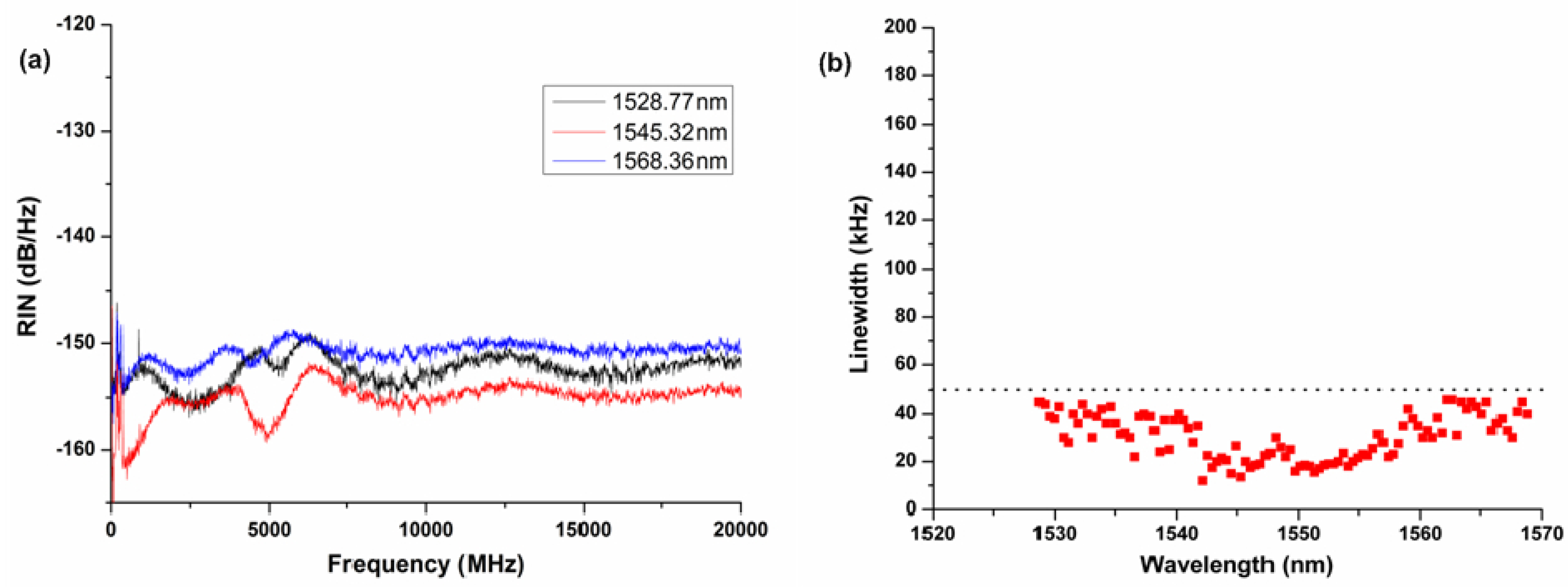
In 2012, Zhang et al. [24] designed a Littman structure using a MEMS uniaxial electrostatically driven mirror as the external tuning element. This tunable laser was simulated and optimized using a two-step hybrid analysis method, which resulted in an output power of more than 13 dBm and an SMSR of more than 55 dB when the injection current was 300 mA, and it ultimately achieved a wide wavelength tuning range of about 40 nm in the C-band with a laser linewidth of less than 50 kHz. The measured relative intensity noise (RIN) is less than −145 dB/Hz from 10 MHz to 20 GHz at all channels, and three typical RIN spectrums in the C-band are shown in Figure 6a. The linewidth is less than 50 kHz over the entire tuning range, as shown in Figure 6b.
In 2018, Shirazi et al. [25] developed a TECSL for optical coherence tomography (OCT) systems. This laser adopts a transmission diffraction grating as the Littman external cavity mode selection device. At an injection current of 150 mA, with an output power of 20 mW and a linewidth of 0.27 nm, the rotating mirror can achieve wavelength tuning from 829.2 nm to 881.5 nm, with a tuning range of up to 52 nm.
In 2018, Chichkov et al. [26] conducted research on a 3.2 µm GasB-based cascade type I quantum well tunable laser. This scheme adopts the improved Littman–Metcalf structure, uses a grating with a line density of 450 lines/mm as the tuning component of the external resonant cavity, and the gain chip is a cascade-pumped GaSb chip with a narrow ridge waveguide structure. The experimental results show that the laser provides a continuous wave output power of 8 mW at room temperature and a peak current of 1.8 A. Moreover, in both continuous wave and pulse modes, the wavelength tuning range exceeds 300 nm.
In 2022, Lv et al. [27] conducted relevant research on a narrow-linewidth titanium-sapphire laser with wide wavelength tunability. An extended prism cavity provided a seed source for the Littman cavity, and the two achieved coupling by sharing some mirrors. By taking advantage of the wide-wavelength tunable characteristic of the prism cavity combined with the linewidth compression characteristic of the Littman cavity, the tunable wavelength range covering 720–884 nm was achieved, and the output spectral linewidth was less than 100 MHz. It is expected to become a new type of laser in the field of high-resolution fluorescence spectroscopy.
In 2022, Zhang et al. [28] proposed a wide-mode hopping-free narrow-linewidth adjustable laser diode source based on diffraction gratings. A mode-free continuous tuning range of 59.13 nm was obtained in the super C-band, and the spectral line width was less than 100 kHz. Under the condition of long-term free operation, it can achieve an optical signal-to-noise ratio (OSNR) greater than 65 dB and an output power greater than 14.8 dBm throughout the entire tuning range.
In 2023, Qiao et al. [29] developed an external cavity swept laser system with a wide jump mode free tuning range and a high SMSR. The proposed wavelength scanning laser is based on a single-angle plane gain chip with a classical Littman external cavity structure and uses a combustion diffraction grating as the feedback element. A wide mode-free continuous wavelength tuning of approximately 100 nm was achieved in the C + L band, and the SMSR was greater than 65.64 dB. The output optical power in the entire tunable region can also reach above 14.12 dBm.
In 2023, Bai et al. [30] demonstrated a high-power, high-repetition-rate, wide-tunable, narrow-linewidth, low-gain band Ti: sapphire laser that uses a seed-self-injection coupling cavity based on Littman gratings and dispersive prisms to reduce the output linewidth. When the pump power is 40.1 W, the maximum power is 2.35 W, and the linewidth is 1.5 pm, which can achieve a stable near-single longitudinal mode output of 690–760 nm.
In 2025, Sheng et al. [31] developed a wide-mode hopping and narrow-linewidth tunable semiconductor laser tube source. This laser adopts a Littman–Metcalf configuration with a diffraction grating. Mode-free tuning has been achieved in the 180 nm wavelength range (1450–1630 nm), with an SMSR of 71.03 dB and a linewidth reduction to 1.63 kHz. Figure 7A shows the combined output spectrum. As can be seen from Figure 7B, when the driving current remains at approximately 400 mA, the tunable semiconductor laser source presented maintains an excellent SMSR throughout the entire scanning range.
In 2025, Wang et al. [32] proposed a dual-module shared external cavity linewidth compression structure with a transmission diffraction grating. With a driving current of 2.4 A and a cooling temperature of 20 °C, the blue diode laser achieves an external cavity output power of 49.8 W, a spectral linewidth of 0.321 nm, a tuning range of 0.817 nm, and an external cavity spectral locking efficiency of about 80.6%.
In 2025, Liu et al. [33] demonstrated a tunable laser operating in the 2 μm band based on a Littman cavity and a shining grating. A wide tuning range of 55 nm (2028–2083 nm) can be achieved. This tunable laser is highly suitable for environmental monitoring, laser therapy, and remote sensing applications.
Table 2 shows the development of Littman-type structure TECSLs. Sheng et al. [31] made a breakthrough in the research of the near-infrared communication band (S + C + L band) based on the Littman-type structure TECSL using the diffraction grating and rotating tuning mirror. This design achieved a continuous tuning range of 180 nm without mode hopping, a remarkable ultra-high SMSR of 71.03 dB, and a linewidth compression of 1.63 kHz. This design is highly suitable for precision applications, such as high-speed coherent communication and high-resolution spectroscopy detection. Wang et al. [32] adopted a dual-module shared Littman-type structure TECSL, combining the transmission diffraction grating and polarization merging technology, and they achieved high power and narrow linewidth in the blue light band. The innovation lies in the coordinated regulation of dual-module currents, which raised the output power to 49.8 W and achieved an efficient mode-locking efficiency of 80.6%. This design is applicable to high-brightness spectral beam combinations, high-precision material processing, marine cleaning, etc.

4. Filter-Type Structure TECSL

4.1. The Structure and Principle of the Filter-Type Structure TECSL

The traditional Littrow- and Littman-type structure TECSLs usually employ diffraction gratings as wavelength-selecting elements. Although this structure can achieve wavelength tuning, its performance is limited by the precise alignment requirements of the gratings, and thus it is highly sensitive to temperature fluctuations and mechanical vibrations. In contrast, the wavelength selection scheme based on narrowband filters provides a new solution to this problem. The filter-type structure TECSL is typically composed of a laser gain chip and an external cavity resonator with an optical filtering function. Its most prominent advantage lies in the extremely high flexibility of the system design. Particularly noteworthy is that the mode selection characteristics of the optical filtering element in the external cavity resonator are the key to achieving single-mode output of the laser.
Figure 8 shows a schematic diagram of the filter-type structure TECSL. This structure utilizes an interference filter as filter for tuning. The laser output by the gain chip passes through the collimating lens, passes through the filter, and then is reflected by the mirror to form laser feedback. By adjusting the filter, the laser wavelength of the output laser can be changed. The wavelength tuning principle of the filter TECSL is achieved by changing the refractive index of the filter, the transmission angle, or the length of the tuning cavity to alter the FSR of the periodic comb spectrum, etc., thereby changing the wavelength position of the maximum transmission peak-to-peak value.
This external cavity structure can also adopt a cat-eye mirror structure, which has self-calibration characteristics [34]. One of the significant advantages of the cat-eye mirror is that it is self-aligning. Regardless of the incident angle, the incident laser beam can return to the diode along the original path in the incident direction after passing through the cat-eye optical system, even if the laser beam is not well collimated. The laser output by the diode passes through the collimating lens and then through the interference filters (IFs), and it is reflected by the cat-eye mirror to form laser feedback. The wavelength of the output laser can be changed by adjusting the angle of the filter.
The relationship between the laser output wavelength λ θ , the incident laser λ 0 , and the angle θ between the filter is shown in Formula (8) [35] as follows:
λ θ = λ 0 1 sin 2 θ n e f f 2
where n e f f represents the effective refractive index. The formula (8) demonstrates that the tunable output wavelength increases as the angle of incidence between the laser and the filter becomes larger. By solving the partial differential of the angle, it can be found that the sensitivity of this structure to the angle is less than that of the grating type, and, therefore, it has better anti-vibration ability.
Commonly used narrowband filters include Fabry–Perot (FP) standards [36], IFs [37], atomic filters, etc. Among them, the FP standards and IFs adopt the multi-beam interference effect for frequency selection.

4.2. Research Progress of the Filter-Type Structure TECSL

In 1975, Voumard et al. [38] reported a scheme of using an FP standard as a laser frequency-selective device. They achieved the TECSL by combining an uncoated semiconductor laser with the FP standard. When using the standard with a fineness of F of about 20, the emission bandwidth was effectively reduced to 0.04 nm without changing the total output power. Furthermore, they proposed that the adoption of standards with higher fineness could further narrow the transmission bandwidth.
In 2011, Zhang et al. [36] utilized the cursor effect of two standard tools to achieve mode selection and improve the SMSR. When the injection current of the prepared TECSL is 400 mA, the output power is 25 mW, the linewidth is less than 100 kHz, the tuning range reaches 40 nm, and the SMSR exceeds 60 dB. In addition to achieving wavelength tuning by changing the cavity length as mentioned above, the FP cavity filter can also be realized by rotating the filter.
In 2016, Han [39] developed a near-infrared (NIR) TECSL based on a semiconductor optical amplifier and two different wavelength-selective components. In this laser, the FP filter is used as the wavelength selection element. By changing the incident angle of the FP cavity filter (ranging from 15.5° to 30° in each system), tuning can be achieved. To achieve wavelength selection, an FP cavity filter was set up in the TECSL. When the injection current is 70 mA, the maximum output power is 3.5 W, and the tuning range is 36 nm (832–868 nm).
In 2019, Wang et al. [40] proposed a wavelength-tunable single-frequency fiber laser based on the spectral narrowing effect in nonlinear semiconductor optical amplifiers (SOAs) and conducted an experimental demonstration. The laser wavelength can be tuned by regulating the central wavelength of the tunable filter (TF) integrated in the laser cavity. The driving current is 100 mA, achieving a wavelength tuning range of 48 nm. The SMSR is as high as 55 dB, and the spectral linewidth is less than 10.1 kHz. A typical delayed self-heterodyne radio frequency (RF) spectrum (the black line) and the corresponding Lorentz curve fitting (the red line) are shown in Figure 9a. Figure 9b shows the measured linewidth and SMSR versus the lasing wavelength during the wavelength tuning process.
In 2020, Zhang et al. [37] introduced the compact and robust TECSL design for space applications. As a wavelength-selective element, the TECSL operates around 698.45 nm. The TECSL uses a narrow-bandwidth IF for spectral selection and a cat-eye reflector for light feedback. By adjusting the IF signal placed in the TECSL oscillator cavity to the position opposite to that of the laser, the output wavelength of the laser can be tuned. Its current control tuning range exceeds 40 GHz. When the current is 65 mA, it emits a laser power of 35 mW with a linewidth of approximately 180 kHz.
In 2021, Priante et al. [41] conducted a study on the tunability and linewidth of the membrane external cavity surface-emitting laser (MECSEL) for well pumping. By adjusting the Bragg reflection filter (BRF), the wavelength tuning range of this laser is from 1124 nm to 1195 nm (71 nm), and the linewidth is 1.7 nm. And, due to the adoption of the 4f multi-pass pump architecture, the output power of MECSEL reaches 28.5 W.
In 2023, Chen et al. [42] developed a hybrid integrated laser source featuring full C-band wavelength tunability and high power output. The TECSL is composed of a gain chip and a double micro-ring narrowband filter integrated on a silicon nitride photonic chip, achieving a wavelength tuning range of 55 nm. The SMSR reaches 51.6 dB, the narrowest linewidth is 2.37 kHz, and the output power reaches 240 mW.
In 2024, Ye et al. [43] proposed a TECSL operating within a wavelength range of approximately 780 nm, equipped with an FP standard and an IF. The IF TECSL with butterfly-style packaging configuration has continuous wavelength tuning within a specified range through precise temperature and current control and has excellent single-mode characteristics. The experimental results show that the SMSR of the IF TECSL is 54 dB, the temperature-controlled mode-free tuning range is 527 GHz (1.068 nm), the output linewidth is 570 Hz, and the output power is 14 mW when the injection current is 100 mA. Figure 10 is the spectrum of the IF TECSL at a driving current of 60 mA and a Thermoelectric Cooler (TEC) temperature of 22.5 °C.
In 2025, Han et al. [44] proposed a TECSL with a narrow linewidth of 780 nm. The angle-adjustable IF is adopted as the mode selection element to achieve a wide wavelength tuning range. By adjusting the power of the thermal electrode on the phase shifter and two MRRs in the Si3N4 dual micro-ring narrowband filter chip, the laser can be tuned. By experimentally injecting a current of 95 mA, a narrow linewidth of 55 kHz and a high output power of 51 mW were obtained, with a tuning range of 5.12 pm.
Table 3 shows the development of filter-type structure TECSLs. Zhang et al. [36] utilized the cursor effect of two standard tools to achieve mode selection and improve SMSRs. They also discovered that, in addition to wavelength tuning through changing the cavity length, the FP cavity filter can also be achieved by rotating the filter. Through experiments, they obtained an SMSR of 60 dB. This performance of the TECSL applies to traditional applications, such as high-speed communication and laser radar. Ye et al. [43] adopted a TECSL operating within a wavelength range of approximately 780 nm, equipped with an FP standard and an IF, setting a new record of 0.57 kHz for ultra-narrow linewidth. The 0.57 kHz ultra-narrow-linewidth record, its miniaturized packaging, and lightweight design give it unique advantages in frontier applications such as quantum precision measurement and atomic interferometers. Han et al. [44] proposed a TECSL with an angle-adjustable IF adopted as the mode selection element to achieve a wide wavelength tuning range, thereby achieving a narrow linewidth of 55 kHz and an output power of 51 mW in the 780 nm band. The filter-type structure TECSL uses the principle of multi-beam interference for filtering, and its stability is superior to that of the grating structure TECSL, and it has a linewidth reduction effect better than kHz.

5. Fiber-Type Structure TECSL

5.1. The Structure and Principle of the Fiber-Type Structure TECSL

Thanks to the continuous progress of fiber Bragg grating technology, researchers have introduced the fiber Bragg grating (FBG) structure in the TECSL.
The structure of the TECSL system based on the FBG is shown in Figure 11. This structure employs a specially designed gain chip, with one end coated with HR coating and the other end prepared with AR coating to achieve efficient coupling. In terms of system integration, the FBG is optically coupled directly with the AR end face of the gain chip through a conical fiber lens, and the other end serves as the end face reflector of the external cavity. The wavelength tuning mechanism of this structure mainly relies on temperature control or mechanical stress adjustment of the FBG, achieving a precise offset of the Bragg wavelength by changing the grating period, thereby completing the continuous tuning of the laser wavelength.
The functional essence of the FBG is a mirror with narrowband high reflection characteristics. It feeds back specific wavelengths within the bandwidth of the Bragg reflection peak into the gain chip, interacts with the active region laser, increases the photon lifetime of this oscillation mode, reduces its threshold, and obtains single-mode output through mode competition. Coupling LD and the FBG with conical fibers can effectively reduce the reflected laser at the end face of LD and suppress the FP oscillation mode in the inner cavity. The Bragg center wavelength of the FBG determines the lasing wavelength of the laser, and the relationship is shown in Formula (9) as follows:
λ B = 2 n e f f Λ
In the formula, λ B is the Bragg center wavelength, n e f f is the refractive index of the fiber core, and Λ is the grating period.
The FBG-type structure TECSL typically uses mechanical, temperature, current, and other means to stretch the FBG to achieve wavelength tuning.
Hybrid designs combining multi-FBG cascades or superstructure FBGs can achieve 10 nm to 20 nm tuning through selective strain/temperature activation, while liquid crystal-based fiber mirrors enable 20 nm to 30 nm electrically tunable ranges. The differential effect in dual-fiber cavities or hybrid fiber–waveguide systems can also extend the tuning range to 100 nm to 200 nm. These designs can enable the tuning range of the fiber-type structure TECSL to expand beyond the limitations of traditional FBGs.

5.2. Research Progress of the Fiber-Type Structure TECSL

In the 1980s, there were relevant reports on fiber Bragg reflectors used for laser mode selection and linewidth voltage narrowing [45]. After more than 30 years of development, researchers have made a large number of improvements and enhancements in this field.
In 2014, Duraev et al. [46] reported an external cavity type single-frequency tunable semiconductor laser based on a single-mode FBG. Experiments have proved that the wavelength tuning function can be achieved by changing the injection current, the temperature of the active region of the laser, and the temperature of the fiber grating. In this study, the current is 175 mA, the laser tuning range is 1.5 nm, the output power can reach 10 mW, the linewidth is 10 kHz, and the SMSR can reach 30 dB.
In 2020, Lindberg et al. [47] constructed a C-cavity with an SOA as the gain medium and modulator and chirped fiber Bragg grating (CFBG) as the reflector at both ends of the resonant cavity and achieved a tuning range of 35 nm (1535–1570 nm) and a linewidth of 0.14 nm in the 1550 nm band, with an output power of about 55 dBm at a current of 480 mA.
In 2021, Congar et al. [48] conducted research on a narrow-linewidth near-ultraviolet InGaN laser based on an external cavity FBG. When the pump current is close to 95 mA, the output power of this laser is 1.3 mW, the SMSR is 44 dB, and the linewidth can reach 16 kHz.
In 2022, Chen et al. [49] demonstrated a narrow-linewidth, high SMSR semiconductor laser based on femtosecond tracing FBG external optical feedback injection locking technology. The tuning range of this laser can reach 45.3 pm, the maximum SMSR is 66.3 dB, and the maximum output power is 134.6 mW when the current is 400 mA. Furthermore, the minimum Lorentz linewidth of the laser was measured to be 260.5 kHz. The experimental results are shown in Figure 12.
In 2023, Gu et al. [50] demonstrated a narrow-linewidth tunable fiber laser based on low-voltage laser-induced graphene paper-heated FBGs. When the pump power is 104.5 mW, the maximum output power is 10.4 mW, which can achieve a linewidth of less than 600 Hz. The SMSR can reach 43 dB. Meanwhile, the central wavelength of the output laser can be continuously adjusted from 1549.5 nm to 1552 nm, with a full range of 2.5 nm.
In 2024, Duraev et al. [51] reported the fabrication of a single-frequency TECSL module with a wavelength of 1550 nm. The outer cavity of this module is an FBG formed in a single-mode fiber. The tuning of the radiation wavelength using piezoelectric ceramic elements was considered. This laser module is capable of generating dynamically stable single-frequency radiation. The emission spectral wavelength of the laser module is tuned to 2 nm, the SMSR can reach 45 dB, the laser linewidth is approximately 100 kHz, and the average output optical power is 50 mW. The output power is 95 mW at an injection current of 400 mA.
In 2025, Cui et al. [52] studied a method of achieving longitudinal energy in a frequency-tunable external cavity semiconductor laser (FTECSL) using a single gain medium, overcoming the mutual limitations between a low damage threshold and laser output power. This method can fully utilize the inherent properties of the semiconductor gain medium. The fiber FP tunable filters (FFPTFs), which served as the primary component for mode selection and wavelength tuning in the FTECSL, are an all-single-mode fiber device with an FP cavity featuring two coated fiber surfaces and a low damage threshold. By manipulating the FFPTF with a driving source, the modulation of the transmitted light wavelength achieves laser wavelength tuning or sweeping. We demonstrated various FTECSL designs, achieving a maximum tuning range of 226.8 nm, a maximum output power of 160 mW, and a maximum OSNR of 86.3 dB under different configurations. Figure 13 illustrates the ultra-wide tunable properties of the FTECSL in two different configurations.
Table 4 shows the development of fiber-type structure TECSLs. A 1 μm band narrow-linewidth semiconductor laser designed by Chen et al. [49] is achieved by coupling a quantum dot gain chip with a femtosecond laser cut-toe FBG, obtaining a high SMSR of 66.3 dB and a narrow linewidth of 260.5 kHz, with an output power of 134.6 mW, making it an ideal seed laser for a high-power fiber laser. Gu et al. [50] demonstrated a narrow-linewidth fiber-type structure TECSL based on low-voltage laser-induced graphene paper-heated FBGs. It achieves an extremely narrow linewidth of 600 Hz and a tuning range of 2.5 nm with excellent stability, which is particularly suitable for high-precision fiber sensing and light detection and ranging (LIDAR) applications. Cui et al. [52] developed a high-power ultra-wide FTECSL with a single gain medium combined with a node loss reconstruction model, achieving an ultra-wide tuning range of 226.8 nm and a high power output of 160 mW, which is suitable for polarization LIDAR and mid-infrared laser generation, etc.

6. Waveguide-Type Structure TECSL

6.1. The Structure and Principle of the Waveguide-Type Structure TECSL

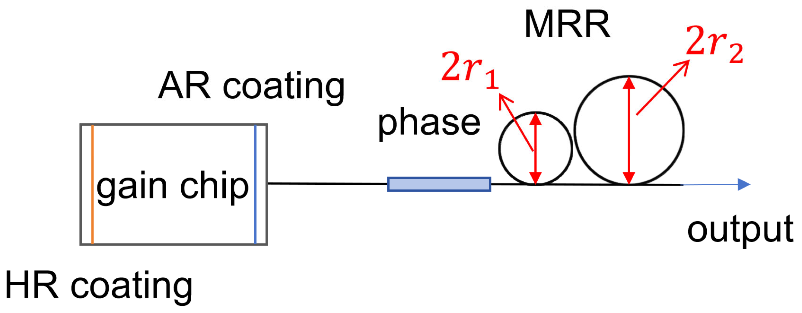
The advancement of photon integration technology has led to significant innovations in external cavity structures. The waveguide external cavity, as a new solution, is gradually replacing the traditional discrete and combined external cavity structures. This innovative design utilizes the characteristics of waveguides to achieve narrow-linewidth laser output. While enabling miniaturization and lightweighting, its outstanding system integration capability significantly improves the mechanical stability and operational reliability of the devices. It is precisely these breakthrough advantages that have drawn widespread attention from the academic and industrial communities in recent years for waveguide external cavity technology. As shown in Figure 14, the micro-ring resonator (MRR)-type structure TECSL is usually formed by coupling an SOA gain chip with a planar optical waveguide serving as the external resonator. Optical waveguides usually have a phase adjustment section and a micro-ring resonator structure. The MRR is a double micro-ring structure with unequal radii, and the mode selection function is achieved through asymmetric coupling. At present, the commonly used MRR optical waveguides include Si basis [53,54,55,56], SiON basis, Si3N4 basis [57,58], etc.
The reduction in the linewidth of this type of laser is mainly achieved through low-loss waveguides, a high Quality factor (Q) in the resonant cavity, and an increase in the effective cavity length. Q is a key parameter for evaluating the energy storage and loss efficiency of a resonant system. Moreover, the micro-ring waveguide structure can significantly increase the effective cavity length at a small size.
The silicon-based waveguide TECSL is a typical structure of waveguide-type structure TECSL. The laser wave coupled to the silicon baseline waveguide by the SOA undergoes filtering through two micro-ring resonators (MRRs). The principle is to set the radii of the two MRRS slightly differently, and the FSR is also different, as shown in Formula (10) [59] as follows:
F S R = λ 2 / 2 π r n e f f
where r is the radius of the MRR and n e f f is the effective refractive index of the MRR silicon waveguide. The transmission spectra of two MRRs are superimposed on each other, and the wavelengths of the mutually matched peaks are determined by mode competition to determine the lasing wavelengths.
Through the thermal-optical effect [60], by adjusting the heater, the FSR of the MRR changes, causing the transport peak to shift. Then, through the Vernier effect, wavelength tuning can be carried out over a wide range.
The MRR serves as a spectral selection structure. The MRR diameter is a key design parameter of the waveguide-type structure TECSL and directly affects the performance of the laser. Increasing the diameter will reduce the FSR, increase the Q, and compress the linewidth, but it will also decrease the tuning efficiency and may excite higher-order modes, while reducing the diameter will increase the FSR and accelerate the tuning response, but it will sacrifice the Q and linewidth.
The MRR-type structure TECSL has the advantages of low cost, low power consumption, high integration, small size, etc. Moreover, its linewidth characteristics are good, and it can easily reach tens of kHz. With the development of the new generation of MRR-type structure TECSLs, the linewidth can reach the order of hundreds of Hz. The optical waveguide has low loss, good filtering characteristics, and generates a high SMSR.
In the waveguide-type structure TECSL, the matching between the SOA and the planar optical waveguide usually requires the use of a conical waveguide or a mode field converter to match the elliptical mode field of the SOA to the circular mode field of the waveguide so that the coupling loss is less than 1 dB. In addition, a polarization-maintaining waveguide or an on-chip polarization rotator is needed to adapt the Transverse Electric polarization advantage of the SOA.

6.2. Research Progress of the Waveguide-Type Structure TECSL

As early as the 1990s, researchers conducted in-depth investigations into the characteristics of MRRs [61]. Over the past two decades or so, semiconductor lasers based on MRRs have developed rapidly, giving rise to various waveguide materials, structures, etc. The spectral output of a single MRR is only a comb spectrum, making it difficult to use it alone as a filter device for wavelength tuning. Therefore, it is often mixed and integrated with other components that can achieve the tuning function to realize the wavelength tuning function.
In 2006, Crozatier et al. [62] developed and characterized a frequency agile-extended cavity diode laser waveguide with an integrated Bragg reflector in Ti: Fe: LiNbO3. The laser has an emission power of up to 7 mW in a 1.5 μm telecommunication window, an emission spectrum with a linewidth of 18 kHz, and an SMSR greater than 40 dB.
In 2009, Mazin et al. [63] invented a 1550 nm TECSL, which etched a narrowband Bragg grating on a silicon-based silica planar optical waveguide, jointly formed a cavity with a semiconductor gain chip, and integrated it into a 14-pin butterfly package. When the injection current was 152 mA, the output power reached 11.5 mW, the SMSR was 54.7 dB, and the laser linewidth was less than or equal to 2.6 kHz.
In 2011, Yoon et al. [64] reported research on the TECSL based on a polymer Bragg reflector (PBR) and a single MRR. When the gain current is 120 mA, its output power is 0.6 mW. The tuning range of this laser in the 1550 nm band is 14.5 nm, and the SMSR is greater than 30 dB.
In 2015, Komljenovic et al. [65] designed an integrated external cavity monolithic semiconductor laser. Through a low-loss silicon waveguide platform, tuning over 54 nm in the O-band was demonstrated. The linewidth measured within the full tuning range was less than 100 kHz, with the best result being approximately 50 kHz and the SMSR reaching over 45 dB. The output power exceeds 10 mW at a current of 70 mA.
In 2018, Radosavljevic et al. [66] fabricated a dual MRR structure on the Ge-on-SOI waveguide platform. By coupling with the laser gain chip, a wavelength tuning range of 108 nm in the 5 µm band was achieved, with an SMSR greater than 20 dB.
In 2020, Xu et al. [67] proposed research on a tunable wavelength laser for hybrid silicon photons based on a cursor, with a tuning range of 66 nm (1881–1947 nm), an SMSR of 35 dB, and an output power of 28 mW at an injection current of 450 mA.
In 2021, Xiang et al. [68] integrated a single MRR on an ultra-high Q-value SiN waveguide with a laser. By leveraging the external cavity feedback of the MRR, an output power of 25 mW could be achieved at a current of 300 mA, and the SMSR could reach 54 dB, enabling a Lorentz linewidth of 1 kHz.
In 2021, Luo et al. [69] conducted research on a C-band high-linear-polarization narrow-linewidth hybrid semiconductor laser. This laser is composed of a semiconductor gain chip and an external cavity high-birefringence waveguide Bragg grating. It was experimentally measured that when the SMSR of this laser reached 50.2 dB, the linewidth was 4.15 kHz, the injection current was 410 mA, and the maximum output power was 8.07 mW.
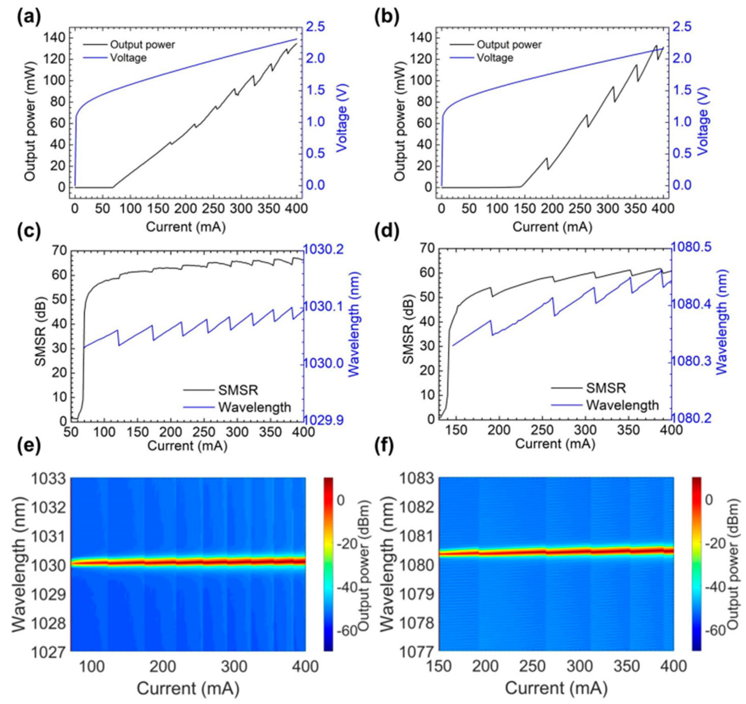
In 2021, Wang et al. [70] studied a narrow-ridge waveguide semiconductor laser tube with an optimized AR coating. Thanks to the laser beam output limited by the fundamental frequency transverse mode working diffraction and the appropriate suppression of the inner cavity mode resonance, the tuning range reached 101 nm. At a current of 250 mA, the maximum SMSR was 56.26 dB, the output power was 35.12 mW, and the line width was 15.1 MHz. As shown in Figure 15, with the emission wavelength tuned to 1940 nm at a driving current of 250 mA and a 283 K heat sink temperature, the Blazed grating external cavity laser (BG-ECL) exhibited single longitudinal mode operation with a maximum SMSR as high as 56.26 dB, illustrating the ultra-high spectral selectivity of our device.
In 2022, Aihara et al. [71] demonstrated a tunable laser composed of a Si lattice filter, a Si ring resonator, and a III-V gain region, using a Si channel waveguide as the lattice filter and the ring resonator. This tunable laser can obtain a single-mode laser, with an output power of approximately 2.3 mW when the current is about 75 mA. The maximum value of the SMSR is approximately 44 dB, the wavelength tuning is 32 nm (1529–1561 nm), and the minimum linewidth is estimated to be 27 kHz.
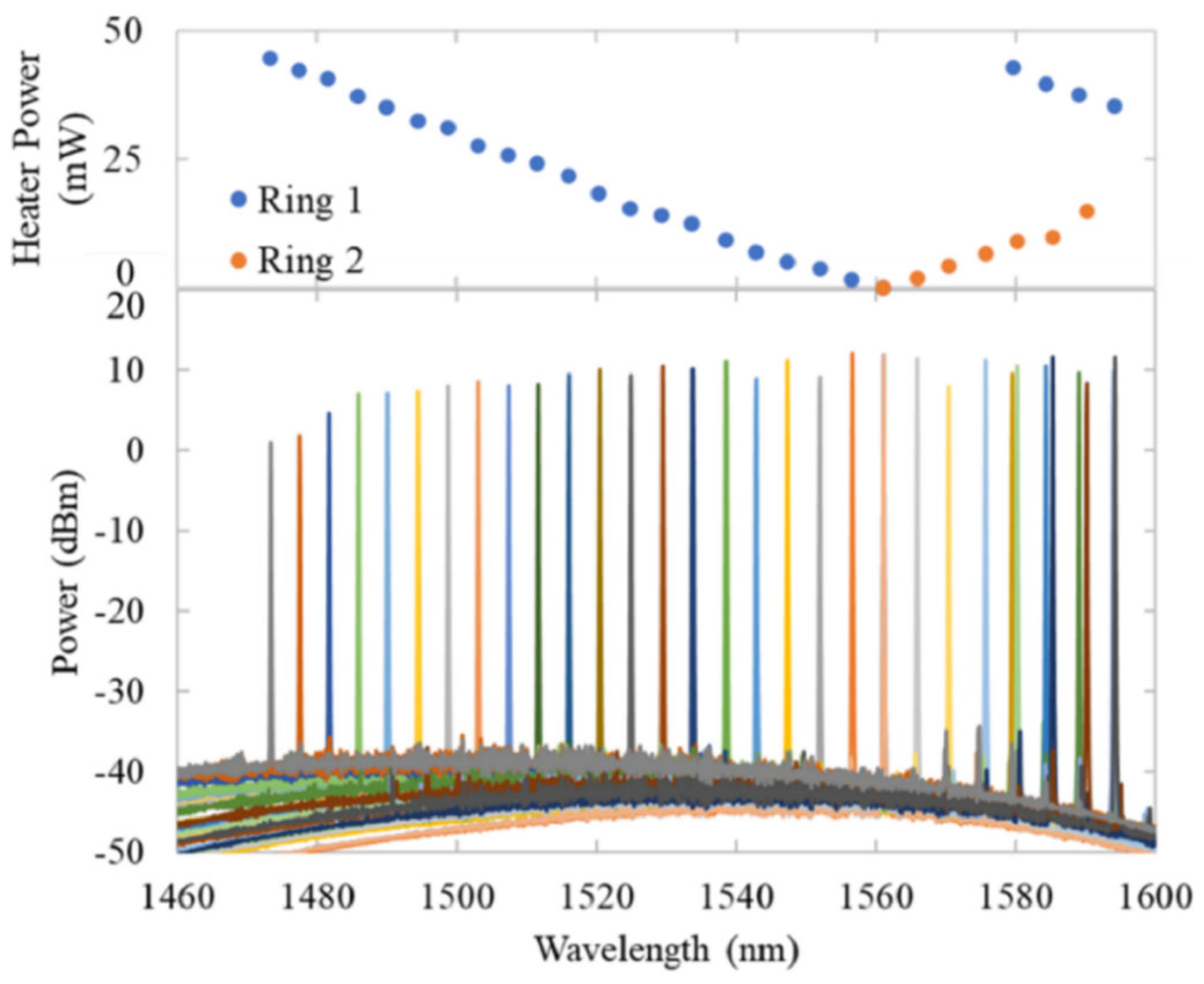
In 2023, Iwanaga et al. [72] demonstrated a hybrid wavelength TECSL tube using a curved directional coupler. The hybrid wavelength TECSL tube consists of a wavelength filter using a double-ring resonator and a curved direct current. Through experiments, when the injection current is 200 mA, the output power can reach 9.15 mW, achieving a tunable wavelength range of 120.9 nm, and the maximum SMSR can reach 42 dB. Figure 16 shows the wavelength tuning spectra with a 200 mA injection current.
In 2025, Yang et al. [73] proposed a narrow-linewidth, high-power, and wide-tunable III-V/Si3N4 hybrid integrated external cavity laser. An SMSR greater than 50 dB was achieved within the wavelength tuning range of 89 nm. At a wavelength of 1550 nm, the maximum output power of the fiber reaches 101.4 mW. The minimum Lorentz linewidth is 0.252 kHz.
Table 5 shows the development of waveguide-type structure TECSLs. Wang [70] et al. achieved an ultra-high SMSR of 56.26 dB and an output power of 35.12 mW in the 1940 nm band with a tuning range of up to 100 nm using a GaSb-based sparkle grating outer-cavity structure with an innovative combination of a narrow-ridge waveguide laser diode and an optimized anti-reflective coating, which makes this high-performance mid-infrared laser source particularly suitable for applications such as gas sensing and spectral analysis. This high-performance laser source is particularly suitable for applications such as gas detection and spectral analysis. Iwanaga et al. [72] innovatively used a curved directional coupler instead of the traditional linear structure, successfully solved the wavelength dependence of the coupling efficiency between the silicon photonic line waveguide and the ring resonator, and realized a record tuning range of 120.9 nm. This makes it applicable to applications such as DWDM and multi-parameter optical sensing networks. Yang et al. [73] developed a high-performance mid-infrared laser source with an ultra-high SMSR and 35.12 mW output power via III-V/Si3N4 hybrid integration technology combined with a triple micro-ring resonator outer cavity design and simultaneously realized an ultra-narrow linewidth of 0.252 kHz, a high power output of 101.4 mW, and a tuning range of 89 nm in the 1550 nm band, with an ultra-low relative intensity noise of −156 dBc/Hz, which makes it applicable to cutting-edge fields such as coherent optical communication, high-precision LIDAR, and ultra-sensitive gas detection.

7. Conclusions

The TECSL exhibits diverse performance characteristics due to its different structural configurations, making it suitable for various professional applications. This article elaborates on the principles of various types of TECSLs and reviews the research results in this field in recent years. The Littrow-type structure TECSL uses diffraction gratings for tuning and has a wide tuning range, such as the laser reported by Giraud et al. [15], which achieved a wide range of continuous tunable output from 3.22 μm to 3.58 μm. It is highly suitable for applications such as LIDAR, but its linewidth is not narrow enough. In contrast, the Littman-type structure TECSL uses an additional rotatable mirror for tuning to achieve excellent spectral purity, and it has an extremely narrow linewidth and excellent SMSR, such as the laser developed by Sheng et al. [31], which achieved a 71.03 dB SMSR and a linewidth of 1.63 kHz. Although its tuning range is narrow and the power output is low, it is suitable for applications such as atomic clocks and high-resolution spectroscopy. The filter-type structure TECSL provides flexible design options through tunable filters, and its performance is closely related to the selected filter, with high development freedom. When using an electrically tunable filter, it can achieve microsecond-level wavelength switching. By combining multiple filters, ultra-narrowband filtering output can be achieved, such as the laser proposed by Ye et al. [43], which achieved an output linewidth of 570 Hz. Therefore, the filter-type structure TECSL is very suitable for spectral imaging and optical coherence tomography. The fiber-type structure TECSL achieves extremely high stability and ultra-narrow linewidth through FBGs, although its tuning range is limited and the power is low, such as the tunable fiber laser demonstrated by Gu et al. [50], which can achieve a linewidth of less than 600 Hz with a tuning range of only 2.5 nm. However, it still meets the strict requirements of optical metrology and gravitational wave detection. The waveguide-type structure TECSL is easy to integrate, has a small volume and low cost, and has good overall linewidth characteristics, such as the laser proposed by Yang et al. [73], with a minimum Lorentz linewidth of 0.252 kHz. It is suitable for photonic integrated circuits and optical sensing. Among them, the external cavity structure of the micro-ring has a relatively balanced tuning range and linewidth characteristics, which makes it suitable for the photonic integration field, and it has broad application prospects.

Author Contributions

Conceptualisation, Z.L., W.L. and J.C.; methodology, C.Y., S.L. and Y.L.; writing—original draft preparation, W.L. and S.Y.; writing—review and editing, X.W. and E.Z.; visualisation, L.L. and X.G.; supervision, D.X. and Y.Q.; funding acquisition, Y.Q. All authors have read and agreed to the published version of the manuscript.

Funding

This work was supported in part by a specific research fund for the Innovation Platform for Academicians of Hainan Province under Grant YSPTZX202513, in part by the Key Research and Development Projects in Hainan Province under Grant ZDYF2025GXJS007, in part by the Hainan Normal University Graduate Students Innovative Scientific Research Project under Grant S202511658042, Grant S202511658046, in part by the Hainan Normal University College Students’ Innovation and Entrepreneurship Open Fund (Banyan Tree Fund) Project under Grant RSXH20231165803X, Grant RSXH20231165811X, Grant RSYH20231165806X, Grant RSYH20231165824X, and Grant RSYH20231165833X, and in part by the National Natural Science Foundation of China under Grant 62464006.

Conflicts of Interest

The authors declare no conflicts of interest.

References

  1. Dupuis, R. An introduction to the development of the semiconductor laser. IEEE J. Quantum Electron. 1987, 23, 651–657. [Google Scholar] [CrossRef]
  2. Hawthorn, J.C.; Weber, P.K.; Scholten, E.R. Littrow configuration tunable external cavity diode laser with fixed direction output beam. Rev. Sci. Instrum. 2001, 72, 4477–4479. [Google Scholar] [CrossRef]
  3. Wei, F.; Sun, Y.; Chen, D.; Xin, G.; Ye, Q.; Cai, H.; Qu, R. Tunable External Cavity Diode Laser with a PLZT Electrooptic Ceramic Deflector. IEEE Photonics Technol. Lett. 2011, 23, 296–298. [Google Scholar]
  4. Sato, T.; Yamaoto, F.; Tsuji, K.; Takesue, H.; Horiguchi, T. An uncooled external cavity diode laser for coarse-WDM access network systems. IEEE Photonics Technol. Lett. 2002, 14, 1001–1003. [Google Scholar] [CrossRef]
  5. Diep, V.N.; Marilou, C.R.; Duong, V.P.; Xuan, N.T.; Thu, V.V.; Hong, P.M. Tunable dual wavelength and narrow linewidth laser using a single solid-state gain medium in a double Littman resonator. Opt. Commun. 2021, 496, 127131. [Google Scholar] [CrossRef]
  6. Stry, S.; Hildebrandt, L.; Sacher, J.; Buggle, C.; Kemmann, M.; Klitzing, W. Compact tunable diode laser with diffraction-limited 1 Watt for atom cooling and trapping. High Power Diode Laser Technol. Appl. II 2004, 5336, 17–25. [Google Scholar]
  7. Labachelerie, M.; Passedat, G. Mode-hop suppression of Littrow grating-tuned lasers. Appl. Opt. 1993, 32, 269–274. [Google Scholar] [CrossRef]
  8. Long, R.; Wang, H.; Gong, Q.; Song, Z.; Feng, S. Optical feedback of semiconductor external cavity laser. Commun. Technol. 2013, 46, 142–144. [Google Scholar]
  9. Hard, T.M. Laser wavelength selector and output coupler. IEEE J. Quantum Electron. 1969, 5, 321. [Google Scholar] [CrossRef]
  10. Loh, H.; Lin, Y.; Teper, I.; Cetina, M.; Simon, J.; Thompson, J.K.; Vuletić, V. Influence of grating parameters on the linewidths of external-cavity diode lasers. Appl. Opt. 2006, 45, 9191–9197. [Google Scholar] [CrossRef] [PubMed]
  11. Chi, M.; Bjarlin, J.O.; Michael, P.P. Tuning range and output power optimization of an external-cavity GaN diode laser at 455 nm. Appl. Opt. 2016, 55, 2263–2269. [Google Scholar] [CrossRef] [PubMed]
  12. Guo, H.; Olamax, G.T. Analysis of no mode-hop tuning of mirror-grating external-cavity diode laser. Opt. Commun. 2018, 421, 90–93. [Google Scholar] [CrossRef]
  13. Chen, M.; Hsiao, S.; Shen, K.; Tsai, C.; Chui, H. Single longitudinal mode external cavity blue InGaN diode laser. Opt. Laser Technol. 2019, 116, 68–71. [Google Scholar] [CrossRef]
  14. Kapasi, D.P.; Eichholz, J.; McRae, T.; Ward, R.L.; Slagmolen, B.J.; Legge, S.; Hardman, K.S.; Altin, P.A.; McClelland, D.E. Tunable narrow-linewidth laser at 2 μm wavelength for gravitational wave detector research. Opt. Express 2020, 28, 3280–3288. [Google Scholar] [CrossRef]
  15. Giraud, E.; Demolon, P.; Gresch, T.; Urio, L.; Muller, A.; Maulini, R. Room-temperature continuous-wave external cavity interband cascade laser tunable from 3.2 to 3.6 µm. Opt. Express 2021, 29, 38291–38297. [Google Scholar] [CrossRef]
  16. Zhao, H.; Jiang, L.; Li, L.; Li, M.; Wang, R.; Yang, Z.; Wang, H.; Yang, W.; Zhang, C.; Hua, W.; et al. Wide-Spectrum Tuning and Narrowing of 780 nm Broad-Area Diode Laser with Littrow-Type Transmission Gratings. Photonics 2024, 11, 948. [Google Scholar] [CrossRef]
  17. Hu, Y.; Chang, Z.; Wang, P.; Hu, C.; Peng, H.; Xiao, Y.; Tang, X. Characterizing and manipulation of the modes of a blue laser diode with a double-grating external cavity. Opt. Laser Technol. 2025, 190, 113184. [Google Scholar] [CrossRef]
  18. Luo, W.; Duan, C. A broadband pulsed external-cavity quantum cascade laser operating near 6.9 µm. Chin. Phys. Lett. 2016, 33, 59–61. [Google Scholar]
  19. Sun, H.; Menhart, S.; Adams, A. Calculation of spectral linewidth reduction of external-cavity strong-feedback semiconductor lasers. Appl. Opt. 1994, 33, 4771–4775. [Google Scholar] [CrossRef]
  20. Littman, M.G.; Metcalf, H.J. Spectrally narrow pulsed dye laser without beam expander. Appl. Opt. 1978, 17, 2224–2227. [Google Scholar] [CrossRef] [PubMed]
  21. Chen, N.; Chen, H.; Liang, C.; Chang, P. A tunable diode laser. In Proceedings of the 10th Anniversary. IMTC/94. Advanced Technologies in I & M. 1994 IEEE Instrumentation and Measurement Technolgy Conference, Hamamatsu, Japan, 10 May 1994. [Google Scholar]
  22. Jin, J.; Jiao, Q.; Li, Y.; Lv, F.; Zhang, G. Study on external-cavity semiconductor laser. Chin. Opt. Lett. 2003, 1, 147–148. [Google Scholar]
  23. Leung, M.K.; Mariampillai, A.; Standish, B.A.; Lee, K.K.; Munce, N.R.; Vitkin, I.A.; Yang, V.X. High-power wavelength-swept laser in Littman telescope-less polygon filter and dual-amplifier configuration for multichannel optical coherence tomography. Opt. Lett. 2009, 34, 2814–2816. [Google Scholar] [CrossRef]
  24. Zhang, D.; Zhao, J.; Yang, Q.; Liu, W.; Fu, Y.; Li, C.; Luo, M.; Hu, S.; Hu, Q.; Wang, L. Compact MEMS external cavity tunable laser with ultra-narrow linewidth for coherent detection. Opt. Express 2012, 20, 19670–19682. [Google Scholar] [CrossRef]
  25. Shirazi, M.F.; Kim, P.; Jeon, M.; Kim, C.S.; Kim, J. Free space broad-bandwidth tunable laser diode based on Littman configuration for 3D profile measurement. Opt. Laser Technol. 2018, 101, 462–467. [Google Scholar] [CrossRef]
  26. Chichkov, N.B.; Yadav, A.; Zherebtsov, E.; Wang, M.; Kipshidze, G.; Belenky, G.; Shterengas, L.; Rafailov, E.U. Wavelength-tunable, GaSb-based, cascaded type-I quantum-well laser emitting over a range of 300 nm. IEEE Photon. Technol. Lett. 2018, 30, 1941–1943. [Google Scholar] [CrossRef]
  27. Lv, R.; Teng, H.; Zhu, J.; Wei, Z. High energy widely tunable narrow-linewidth Ti: Sapphire laser using combined-cavity configuration. Opt. Express 2022, 30, 16289–16296. [Google Scholar] [CrossRef] [PubMed]
  28. Zhang, A.; Qiao, S.; Sheng, L.; Huang, L.; Liu, Z.; Ju, J.; Zhang, Z.; Yin, B.; Li, P.; Liu, J.; et al. Study on external cavity diode laser with a wide mode-hopping free tuning range. Front. Phys. 2022, 10, 1093179. [Google Scholar] [CrossRef]
  29. Qiao, S.; Sheng, L.; Huang, L.; Zhang, A.; Wei, Y.; Liu, Z.; Ju, J.; Zhang, Z.; Yin, B.; Li, P.; et al. High-SMSR wavelength-swept laser with a CL-band mode-hopping free tuning range. Front. Phys. 2023, 11, 1155266. [Google Scholar] [CrossRef]
  30. Bai, Y.; Ding, X.; Dai, X.; Su, N.; Lei, P.; Jiang, G.; Zhang, X.; Li, X.; Wu, L.; Zhang, G.; et al. High-power and high-repetition-rate widely tunable narrow-linewidth low-gain-band Ti: Sapphire laser. Opt. Laser Technol. 2023, 163, 109401. [Google Scholar] [CrossRef]
  31. Sheng, L.; Liu, Z.; Wang, J.; Liu, L.; Yin, B.; Zhang, Z.; Zhou, S.; Huang, L. Mode-hop-free wavelength-tunable semiconductor lasers covering the S+ C+ L band via external-cavity optical feedback. Front. Phys. 2025, 13, 1586316. [Google Scholar] [CrossRef]
  32. Wang, X.; Duan, C.; Xiong, Y.; Hu, X.; Tang, X.; Xiao, Y.; Peng, H.; Yang, W. Dual-module combination with Littman crosstalk external cavity for narrow-linewidth blue diode laser. Opt. Laser Technol. 2025, 181, 111901. [Google Scholar] [CrossRef]
  33. Liu, J.; Lu, J.; Zheng, F.; Hou, Z.; Zhou, G.; Xia, C. Tunable 2-μm Waveband Tm3+/Ho3+ Co-doped Lanthanum Aluminosilicate Double-Clad Photonic Crystal Fibre Laser. J. Opt. 2025, 27, 065402. [Google Scholar] [CrossRef]
  34. Zorabedian, P.; Trutna, W.R. Interference-filter-tuned, alignment-stabilized, semiconductor external-cavity laser. Opt. Lett. 1988, 13, 826–828. [Google Scholar] [CrossRef]
  35. Baillard, X.; Gauguet, A.; Bize, S.; Lemonde, P.; Laurent, P.; Clairon, A.; Rosenbusch, P. Interference-filter-stabilized external-cavity diode lasers. Opt. Commun. 2006, 266, 609–613. [Google Scholar] [CrossRef]
  36. Zhang, X.; Wang, N.; Gao, L.; Feng, M.; Chen, B.; Tsang, Y.; Liu, A. Narrow-linewidth external-cavity tunable lasers. In Proceedings of the 10th International Conference on Optical Communications and Networks, Guangzhou, China, 5 November 2011. [Google Scholar]
  37. Zhang, L.; Liu, T.; Chen, L.; Xu, G.; Jiang, C.; Liu, J.; Zhang, S. Development of an interference filter-stabilized external-cavity diode laser for space applications. Photonics 2020, 7, 12. [Google Scholar] [CrossRef]
  38. Voumard, C.; Salathé, R.; Weber, H. Mode selection by etalons in external diode laser cavities. Appl. Phys. 1975, 7, 123–126. [Google Scholar] [CrossRef]
  39. Han, Z. Tunable External Cavity Ring Laser with Wavelength Selective Elements. Master’s Thesis, Iowa State University, Ames, IA, USA, 2016. [Google Scholar]
  40. Wang, L.; Cao, Y.; Wan, M.; Wang, X.; Feng, X.; Guan, B.; Yao, J. Tunable single-frequency fiber laser based on the spectral narrowing effect in a nonlinear semiconductor optical amplifier. Opt. Express 2016, 24, 29705–29713. [Google Scholar] [CrossRef]
  41. Priante, D.; Zhang, M.; Albrecht, A.R.; Bek, R.; Zimmer, M.; Nguyen, C.L.; Follman, D.P.; Cole, G.D.; Sheik-Bahae, M. In-well pumping of a membrane external-cavity surface-emitting laser. IEEE J. Sel. Top. Quantum Electron. 2021, 28, 1–7. [Google Scholar] [CrossRef]
  42. Chen, C.; Wei, F.; Han, X.; Su, Q.; Pi, H.; Xin, G.; Wu, H.; Stroganov, A.; Sun, Y.; Ren, W.; et al. Hybrid integrated Si3N4 external cavity laser with high power and narrow linewidth. Opt. Express 2023, 31, 26078–26091. [Google Scholar] [CrossRef]
  43. Ye, J.; Guan, C.; Lv, P.; Wang, W.; Chen, X.; Wang, Z.; Xiao, Y.; Zhan, L.; Gong, J.; Yao, Y. 780 nm Narrow Linewidth External Cavity Diode Laser for Quantum Sensing. Sensors 2024, 24, 7237. [Google Scholar] [CrossRef] [PubMed]
  44. Han, B.; Shi, Y.; Tang, X.; Li, J.; Guan, C.; Ye, J.; Shen, R. Precisely Tunable 780 nm External Cavity Diode Laser. Photonics 2025, 12, 293. [Google Scholar] [CrossRef]
  45. Brinkmeyer, E.; Brennecke, W.; Zürn, M.; Ulrich, R. Fibre Bragg reflector for mode selection and line-narrowing of injection lasers. Electron. Lett. 1986, 22, 134–135. [Google Scholar] [CrossRef]
  46. Duraev, V.P.; Medvedev, S.V. Single-frequency tunable semiconductor lasers. Semiconductors 2014, 48, 120–122. [Google Scholar] [CrossRef]
  47. Lindberg, R.; Laurell, F.; Fröjdh, K.; Margulis, W. C-cavity fiber laser employing a chirped fiber Bragg grating for electrically gated wavelength tuning. Opt. Express 2020, 28, 9208–9215. [Google Scholar] [CrossRef]
  48. Congar, A.; Gay, M.; Perin, G.; Mammez, D.; Simon, J.C.; Besnard, P.; Rouvillain, J.; Georges, T.; Lablonde, L.; Robin, T.; et al. Narrow linewidth near-UV InGaN laser diode based on external cavity fiber Bragg grating. Opt. Lett. 2021, 46, 1077–1080. [Google Scholar] [CrossRef]
  49. Chen, J.; Chen, C.; Guo, Q.; Qin, L.; Zhang, J.; Peng, H.; Zhou, Y.; Sun, J.; Wu, H.; Yu, Y.; et al. A 1-μm-band injection-locked semiconductor laser with a high side-mode suppression ratio and narrow linewidth. Sensors 2022, 22, 9239. [Google Scholar] [CrossRef]
  50. Gu, B.; Yang, F.; Shen, L.; Zhou, S.; Wang, S.; Wang, S. Narrow-Linewidth Tunable Fiber Laser Based on Laser-Induced Graphene Heated Fiber Bragg Grating with Low Voltage. Photonics 2023, 10, 136. [Google Scholar] [CrossRef]
  51. Duraev, V.P.; Voronchenko, S.A.; Medvedev, S.V.; Lebedev, M.R. Single-frequency tunable external-cavity semiconductor lasers emitting at 1550 nm. Bull. Lebedev Phys. Inst. 2024, 51, S185–S190. [Google Scholar] [CrossRef]
  52. Cui, Q.; Lei, Y.; Yang, C.; Liang, L.; Jia, P.; Wang, H.; Qiu, C.; Zhang, D.; Chen, Y.; Song, Y.; et al. High-power and ultra-wide-tunable fiber-type external-cavity diode lasers. Opt. Laser Technol. 2025, 181, 111899. [Google Scholar] [CrossRef]
  53. Ojanen, S.P.; Viheriälä, J.; Cherchi, M.; Zia, N.; Koivusalo, E.; Karioja, P.; Guina, M. GaSb diode lasers tunable around 2.6 μm using silicon photonics resonators or external diffractive gratings. Appl. Phys. Lett. 2020, 116, 081105. [Google Scholar] [CrossRef]
  54. Chu, T.; Fujioka, N.; Ishizaka, M. Compact, lower-power-consumption wavelength tunable laser fabricated with silicon photonic wire waveguide micro-ring resonators. Opt. Express 2009, 17, 14063–14068. [Google Scholar] [CrossRef] [PubMed]
  55. Dong, F.; Liu, A.; Wang, H.; Zheng, W. Design of double-ring resonator for tunable lasers on silicon. In Proceedings of the Optoelectronics and Micro/Nano-Optics, Beijing, China, 24 October 2017. [Google Scholar]
  56. Guan, H.; Novack, A.; Galfsky, T.; Ma, Y.; Fathololoumi, S.; Horth, A.; Huynh, T.N.; Roman, J.; Shi, R.; Caverley, M.; et al. Widely-tunable, narrow-linewidth III-V/silicon hybrid external-cavity laser for coherent communication. Opt. Express 2018, 26, 7920–7933. [Google Scholar] [CrossRef]
  57. Dass, D.; Costas, M.T.; Barry, L.P.; O’Duill, S.; Roeloffzen, C.G.; Geuzebroek, D.; Carpintero, G.; Guzman, R.C.; Browning, C. 28 GBd PAM-8 transmission over a 100 nm range using an InP-Si3N4 based integrated dual tunable laser module. Opt. Express 2021, 29, 16563–16571. [Google Scholar] [CrossRef]
  58. Lin, Y.; Browning, C.; Timens, R.B.; Geuzebroek, D.H.; Roeloffzen, C.G.; Hoekman, M.; Geskus, D.; Heideman, R.G.; Fan, Y.; Boller, K.J.; et al. Characterization of hybrid InP-TriPleX photonic integrated tunable lasers based on silicon nitride (Si3N4/SiO2) microring resonators for optical coherent system. IEEE Photon. J. 2018, 10, 1–8. [Google Scholar] [CrossRef]
  59. Takeuchi, T.; Takahashi, M.; Suzuki, K.; Watanabe, S.; Yamazaki, H. Wavelength tunable laser with silica-waveguide ring resonators. IEICE Trans. Electron. 2009, 92, 198–204. [Google Scholar] [CrossRef]
  60. Della Corte, F.G.; Esposito Montefusco, M.; Moretti, L.; Rendina, I.; Cocorullo, G. Temperature dependence analysis of the thermo-optic effect in silicon by single and double oscillator models. J. Appl. Phys. 2000, 88, 7115–7119. [Google Scholar] [CrossRef]
  61. Hagness, S.C.; Rafizadeh, D.; Ho, S.T.; Taflove, A. FDTD microcavity simulations: Design and experimental realization of waveguide-coupled single-mode ring and whispering-gallery-mode disk resonators. J. Lightwave Technol. 1997, 15, 2154–2165. [Google Scholar] [CrossRef]
  62. Crozatier, V.; Das, B.K.; Baïli, G.; Gorju, G.; Bretenaker, F.; Le Gouët, J.L.; Lorgere, I.; Sohler, W. Highly coherent electronically tunable waveguide extended cavity diode laser. IEEE Photon. Technol. Lett. 2006, 18, 1527–1529. [Google Scholar] [CrossRef]
  63. Alalusi, M.; Brasil, P.; Lee, S.; Mols, P.; Stolpner, L.; Mehnert, A.; Li, S. Low noise planar external cavity laser for interferometric fiber optic sensors. Fiber Opt. Sens. Appl. VI 2009, 7316, 235–247. [Google Scholar]
  64. Yoon, K.H.; Kwon, O.K.; Kim, K.S.; Choi, B.S.; Oh, S.H.; Kim, H.S.; Sim, J.S.; Kim, C.S. Ring-resonator-integrated tunable external cavity laser employing EAM and SOA. Opt. Express 2011, 19, 25465–25470. [Google Scholar] [CrossRef] [PubMed]
  65. Komljenovic, T.; Srinivasan, S.; Norberg, E.; Davenport, M.; Fish, G.; Bowers, J.E. Widely tunable narrow-linewidth monolithically integrated external-cavity semiconductor lasers. IEEE J. Sel. Top. Quantum Electron. 2015, 21, 214–222. [Google Scholar] [CrossRef]
  66. Radosavljevic, S.; Beneitez, N.T.; Katumba, A.; Muneeb, M.; Vanslembrouck, M.; Kuyken, B.; Roelkens, G. Mid-infrared Vernier racetrack resonator tunable filter implemented on a germanium on SOI waveguide platform. Opt. Mater. Express 2018, 8, 824–835. [Google Scholar] [CrossRef]
  67. Sia, J.X.B.; Wang, W.; Qiao, Z.; Li, X.; Guo, T.X.; Zhou, J.; Littlejohns, C.G.; Liu, C.; Reed, G.T.; Wang, H. Analysis of Compact Silicon Photonic Hybrid Ring External Cavity (SHREC) Wavelength-Tunable Laser Diodes Operating from 1881–1947 nm. IEEE J. Quantum Electron. 2020, 56, 1–11. [Google Scholar] [CrossRef]
  68. Xiang, C.; Guo, J.; Jin, W.; Wu, L.; Peters, J.; Xie, W.; Chang, L.; Shen, B.; Wang, H.; Yang, Q.; et al. High-performance lasers for fully integrated silicon nitride photonics. Nat. Commun. 2021, 12, 6650. [Google Scholar] [CrossRef]
  69. Luo, X.; Chen, C.; Ning, Y.; Zhang, X.; Qiu, C.; Chen, J.; Yin, X.; Qin, L.; Wang, L. High linear polarization, narrow linewidth hybrid semiconductor laser with an external birefringence waveguide Bragg grating. Opt. Express 2021, 29, 33109–33120. [Google Scholar] [CrossRef]
  70. Wang, T.; Yang, C.; Zhang, Y.; Chen, Y.; Shang, J.; Zhang, Y.; Xu, Y.; Niu, Z. High spectral purity GaSb-based blazed grating external cavity laser with tunable single-mode operation around 1940 nm. Opt. Express 2021, 29, 33864–33873. [Google Scholar] [CrossRef]
  71. Aihara, T.; Hiraki, T.; Fujii, T.; Takeda, K.; Tsuchizawa, T.; Kakitsuka, T.; Fukuda, H.; Matsuo, S. Heterogeneously integrated widely tunable laser using lattice filter and ring resonator on Si photonics platform. Opt. Express 2022, 30, 15820–15829. [Google Scholar] [CrossRef] [PubMed]
  72. Iwanaga, K.; Tomimura, Y.; Kita, T. Hybrid laser diode with ultrawide wavelength-tunable range using curved directional couplers. Opt. Express 2023, 31, 34946–34953. [Google Scholar] [CrossRef]
  73. Yang, C.; Li, Y.; Cui, Q.; Liang, L.; Qin, L.; Huang, L.; Chen, Y.; Wang, Y.; Song, Y.; Qiu, C.; et al. Narrow-linewidth, high-power, widely-tunable III-V/Si3N4 hybrid integrated external cavity laser. Opt. Laser Technol. 2025, 186, 112627. [Google Scholar] [CrossRef]
Figure 1. Schematic diagram of the basic structure of the Littrow-type structure TECSL: (a) schematic diagram of Type-A Littrow grating feedback external cavity structure; (b) schematic diagram of Type-B Littrow grating feedback external cavity structure.
Coatings 15 01010 g001
Figure 2. (a) Measured optical output power (after the isolator) as a function of injection current into the TECSL at 1920 nm; (b) coarse wavelength tuning range with an injection current of 400 mA. The FWHM (−3 dB) tuning range is 120 nm [14].
Coatings 15 01010 g002
Figure 3. Measured emission spectra of the diffraction grating from different angles [15].
Coatings 15 01010 g003
Figure 4. Schematic diagram of the basic structure of the Littman-type structure TECSL.
Coatings 15 01010 g004
Figure 5. Schematic diagram of Littman-type structure TECSL mode selection. (a) Medium-gain curve and loss curve; (b) gain chip spectrogram; (c) external cavity spectrogram; (d) gain saturation competition; (e) mode competition results in a single longitudinal mode.
Coatings 15 01010 g005
Figure 6. (a) Measured RIN results; (b) spectral linewidth in C-band [24].
Coatings 15 01010 g006
Figure 7. (A) The superimposed output optical spectra at different resonance wavelengths; (B) the SMSR versus the resonant output wavelength at a drive current of about 400 mA [31].
Coatings 15 01010 g007
Figure 8. Schematic diagram of the filter-type structure TECSL.
Coatings 15 01010 g008
Figure 9. (a) The RF spectrum measured using the delayed self-heterodyne method; (b) the linewidth and SMSR versus the tuning wavelength [40].
Coatings 15 01010 g009
Figure 10. Spectra of the IF TECSL at a driving current of 60 mA and a TEC temperature of 22.5 °C [43].
Coatings 15 01010 g010
Figure 11. Schematic diagram of the FBG-type structure TECSL.
Coatings 15 01010 g011
Figure 12. The P-I-V curves of the (a) 1030 nm and (b) 1080 nm lasers; (c,d) show the changes in wavelength and SMSR versus the injection currents; (e,f) are the jet color maps of the laser spectra with injection currents [49].
Coatings 15 01010 g012
Figure 13. FTECSL tuning spectrum with (a) Configuration A and (b) Configuration B; (c) continuous tuning spectrum [52].
Coatings 15 01010 g013
Figure 14. Schematic diagram of the MRR-type structure TECSL.
Coatings 15 01010 g014
Figure 15. The lasing spectrum from the BG-ECL operating at 250 mA [70].
Coatings 15 01010 g015
Figure 16. Wavelength tuning spectra and corresponding heater power of the double ring. The injection current of the SOA was 200 mA [72].
Coatings 15 01010 g016
Table 1. Research progress of Littrow-type structure TECSLs.
TypeTuning Range
(nm)
Wavelength Coverage
(nm)
LinewidthSMSR (dB)Current (mA)Power (mW)Year
Littrow1201860–198020 kHz-4009.32020 [14]
Littrow3603220–3580-35192132021 [15]
Littrow9773.5–782.50.17 nm20700030502024 [16]
Littrow8.6439.4–44830 pm-400362025 [17]
Table 2. Research progress of Littman-type structure TECSLs.
TypeTuning Range
(nm)
Wavelength
Coverage
(nm)
LinewidthSMSR (dB)Current (mA)Power (mW)Year
Littman9.88797.38–807.260.06 nm20-17.92003 [22]
Littman401528.77–1568.3650 kHz5530019.952012 [24]
Littman52829.2–881.50.27 nm-150202018 [25]
Littman59.131520.82–1579.95100 kHz--30.22022 [28]
Littman1001520–1620-65.64-25.822023 [29]
Littman70690–7601.5 pm--23502023 [30]
Littman1801450–16301.63 kHz71.03--2025 [31]
Littman0.817442.993–443.2650.321 nm-240049802025 [32]
Table 3. Research progress of filter-type structure TECSLs.
Filter
Type
Tuning Range
(nm)
Wavelength Coverage
(nm)
LinewidthSMSR (dB)Current (mA)Power (mW)Year
FP4015XX–15XX100 kHz60400252011 [36]
TF481550.67–1598.7810.1 kHz55100-2019 [40]
IF0.065498180 kHz-65352020 [37]
BRF711124–11951.7 nm--28502021 [41]
MRRs551529.37–1584.132.37 kHz51.615002402023 [42]
IF1.07779.07–781.040.57 kHz54100142024 [43]
IF0.076780.212–780.28855 kHz-95512025 [44]
Table 4. Research progress of fiber-type structure TECSLs.
Fiber
Type
Tuning Range
(nm)
Wavelength Coverage
(nm)
LinewidthSMSR (dB)Current (mA)Power (mW)Year
FBG1.5-10 kHz30175102014 [46]
CFBG351535–15700.14 nm-480316,227.72020 [47]
FBG--16 kHz44951.32021 [48]
FBG0.04531080260.5 kHz66.3400134.62022 [49]
FBG2.51549.5–15520.6 kHz43-10.42023 [50]
FBG21549–1551100 kHz45400952024 [51]
FFPTF226.81435.7–1662.5--9001602025 [52]
Table 5. Research progress of waveguide-type structure TECSLs.
Spectral
Selection
Element
Tuning Range
(nm)
Wavelength Coverage
(nm)
LinewidthSMSR (dB)Current (mA)Power (mW)Year
Bragg grating--18 kHz40-72006 [62]
MRRs14.51542.7–1557.2-301200.62011 [64]
Ring resonator541237.7–1292.450 kHz4570102015 [65]
MRRs661881–194735 kHz-450282020 [67]
MRRs-15481 kHz54300252021 [68]
Bragg grating-155X–155X4.15 kHz50.24108.072021 [69]
Blazed grating1011909–201015.1 MHz56.2625035.122021 [70]
Ring resonator321529–156127 kHz44752.32022 [71]
Ring resonator120.91473.3–1594.2-422009.152023 [72]
Ring resonator8915XX–15XX0.252 kHz50-101.42025 [73]
Disclaimer/Publisher’s Note: The statements, opinions and data contained in all publications are solely those of the individual author(s) and contributor(s) and not of MDPI and/or the editor(s). MDPI and/or the editor(s) disclaim responsibility for any injury to people or property resulting from any ideas, methods, instructions or products referred to in the content.