Article

Fabrication of Biomimetical TiO2@PVDF Composite Membrane with Omniphobicity via In-Situ Growth and Its Anti-Fouling Performance

1
China Electric Power Research Institute, Beijing 100192, China
2
College of Environmental Science and Engineering, Nankai University, Tianjin 300350, China
*
Author to whom correspondence should be addressed.
Coatings 2025, 15(8), 965; https://doi.org/10.3390/coatings15080965
Submission received: 23 July 2025 / Revised: 15 August 2025 / Accepted: 17 August 2025 / Published: 19 August 2025

Abstract

Commercial hydrophobic membranes encounter severe problems such as membrane wetting and membrane fouling under extreme conditions, which affect membrane separation performance. To enhance the anti-fouling abilities of hydrophobic membranes, a composite membrane with omniphobic characteristics was fabricated successfully in this paper. Titanium dioxide (TiO2) nanoparticles were in-situ grown via the hydrothermal synthesis method, and then fluorosilane with low surface energy was grafted on polyvinylidene fluoride (PVDF) membranes. Subsequently, the morphologies, chemical compositions, wetting properties and structural parameters of composite membranes were characterized systematically. Various contaminants were added to the feed to investigate the anti-fouling and anti-wetting performances of the composite membrane in membrane distillation tests. The results showed that butyl titanate was first hydrolyzed to form titanium hydroxide (Ti(OH)4) and then it was dehydrated to form TiO2 in the hydrothermal environment. TiO2 crystals continued to grow and formed rough morphology with micro-nano synergistic distribution, which is similar to a “sunflower” disk composed of cubic clusters and nanopillars. Meanwhile, fluorosilane successfully was grafted onto TiO2. The contact angles of deionized water, 0.4 mM sodium dodecyl sulfate (SDS) solution and 0.2% v/v mineral oil emulsion on the composite membrane surface were 167.3°, 162.0° and 158.5°, respectively, endowing the composite membrane with excellent omniphobic features. In direct contact membrane distillation (DCMD) tests, the composite membrane exhibited a relatively stable membrane permeate flux, and the salt rejection rate almost reached 100%. The mixture, consisting of inorganic salts, organic substances, surfactants and oil emulsions, was used as feed. In contrast, the commercial PVDF membrane flux decreased drastically and even dropped to 0 due to the membrane fouling and wetting. As for the pristine PVDF membrane, the membrane surface was covered with pollutants and membrane pores were blocked. Therefore, it was proved that the omniphobic composite membrane possesses outstanding anti-fouling and anti-wetting performance.

Graphical Abstract

1. Introduction

With sustainable economic growth and rapid industrialization development, the demand for freshwater is increasing gradually. The excessive exploitation and utilization of non-renewable resources has led to ecological damage, and the freshwater system is contaminated severely, thereby exacerbating the crisis of freshwater scarcity [1,2,3]. The rational development, efficient utilization and optimal allocation of water resources will be effective measures to resolve the problem of water shortage. It is well-known that the volume of oceans is high on a global scale. Freshwater can be extracted from seawater by removing salts and minerals [4,5,6]. The desalination and sterilization of industrial wastewater and polluted water sources can also yield freshwater, applied to industrial production and daily life. Thus, desalination technology presents a viable solution to alleviate the freshwater crisis [7,8].
Due to different forms of separation, conventional desalination and water purification technologies mainly include traditional thermal treatment methods and membrane separation methods [9,10]. Compared with traditional thermal treatment means, membrane separation technologies have numerous advantages, such as less equipment footprint, lower energy consumption and simpler operation processes [11,12]. Based on this, membrane separation is widely applied for desalination. Membrane distillation (MD), as an emerging membrane separation technology, combines traditional thermal processing technology with separation membranes. Vapor and other volatile components in the feed pass through membrane pores to the permeate side and then condense into liquids. The mass transfer driving force originates from the vapor pressure difference generated by the temperature difference across the hydrophobic membrane during membrane distillation [13,14]. With the unique advantages of handling high-salinity solutions, high separation efficiency and effective utilization of low-grade renewable energy, MD demonstrates potential applications in the field of desalination [15,16,17]. It is expected to achieve the goals of wastewater reuse treatment and zero liquid discharge (ZLD) proposed in the 14th Five-Year Plan [18,19,20].
MD membranes play a crucial role in the membrane distillation process, with their performance directly influencing separation efficiency and permeate quality. Various factors such as the issues of membrane fouling and membrane wetting and the lack of suitable MD membranes have hindered the development and large-scale industrial application of membrane distillation technology [21,22,23,24]. The limitations of inherent hydrophobicity and structural composition make hydrophobic membrane surfaces prone to contamination, leading to the blockage and wetting of membrane pores and thus affecting MD performance. The presence of humic acid organic compounds, surfactants and oil contaminants in brine poses significant challenges for current commercial hydrophobic membranes. Alleviating membrane fouling and inhibiting membrane wetting have been hot research topics in membrane distillation processes over the years [25,26,27].
Omniphobic membranes with distinctive hydrophobic and oleophobic properties are regarded as potential solutions to deal with challenges from membrane fouling and wetting. These membranes exhibit superior resistance to inorganic salts, organic compounds, surfactants and oil contaminants, originated from hierarchical re-entrant morphology structure and low-solid surface energy. Numerous studies have indicated that an omniphobic surface can be prepared generally via two steps, namely, constructing re-entrant structures with the assistance of nanoparticles and introducing low-surface-energy fluoridation [28]. Conventional fabrication methodologies contain phase inversion and electrospinning with blending nanomaterial and surface modification to impart re-entrant morphology, such as dip-coating, electrospraying, chemical vapor deposition, tetrafluoromethane (CF4) plasma etching treatment, and so on [29,30,31,32]. Li et al. [29] fabricated an FZnO-PVDF omniphobic membrane by the electrospinning method, incorporating ZnO nanorods and dip-coating with 1H,1H,2H,2H-perfuorodecyltriethoxysilane. The results indicated that the FZnO-PVDF membrane exhibited high contact angles towards water droplets (~164.9°) and ethanol solution (~121.1°) and a low sliding angle (~10.5°). Feng et al. [30] constructed omniphobic membranes by depositing silica nanoparticles (SiNPs) on the surface with the electrospraying method and using fluorination for the membrane surface. The effects of the physical properties of SiNPs on membrane performance were analyzed comprehensively. The results revealed that modified membranes exhibited remarkably enhanced performance compared with a commercial PVDF membrane. However, SiNPs aggregated significantly and formed a surface layer with uncontrollable defects. The aggregations of nanoparticles are undesirable for re-entrant architecture. As a quite simple and low-cost method, the hydrothermal method could provide high purity and good dispersibility for synthesizing nanostructures [33,34]. Additionally, it is easy to control the shape and size of synthesized nanostructures. Herein, we propose to construct re-entrant structures via the hydrothermal method.
To address these issues, MD membranes with superior anti-fouling and wetting-resistant properties were fabricated via structural innovations and surface chemical modifications for current hydrophobic membranes in this study. Using the hydrothermal method, titanium dioxide (TiO2) nanoparticles were grown in-situ on polyvinylidene fluoride (PVDF) membranes, and the micro-nano synergistic distribution of rough topography similar to a “sunflower” head was constructed, composed of “cube” clusters and nano-pillars. The membranes were then modified by grafting low-surface-energy fluorosilane on the surface, and biomimetic omniphobic composite membranes were attained. The morphology, chemical composition, wetting property, and structural parameter of the composite membrane were characterized systematically. Various pollutants were added to the feed solution to investigate the anti-fouling and anti-wetting performance of the composite membrane in membrane distillation fouling tests, including inorganic salts, organic compounds, surfactants and oil emulsions.

2. Experimental

2.1. Materials and Chemicals

Dopamine hydrochloride (98%), hydrochloric acid (HCl, 36.5%–38%), Tetrabutyl titanate (TBOT, 98%), humic acid (HA, 90%), sodium chloride (NaCl, 99.5%), calcium chloride (CaCl2, 97%), magnesium sulfate (MgSO4, 99.5%), mineral oil and sodium dodecyl sulfate (SDS, 92.5%) were purchased from Shanghai Aladdin Biochemical Technology Co., Ltd., Shanghai, China. Tris(hydroxymethyl)-aminomethane (Tris, 99%), 1H,1H,2H,2H-perfluorodecyltriethoxysilane (CF3(CF2)7(CH2)2Si(OC2H5)3, PFDTS, 96%), anhydrous ethanol (99.7%) and isopropanol (IPA, 99.5%) were furnished from Shanghai Macklin Biochemical Technology Co., Ltd., Shanghai, China. PVDF flat sheet membranes (Durapore, 0.22 μm) were provided by Merck Millipore (China) Co., Ltd., Shanghai, China. Deionized water (DI) was produced from an ultrapure water purification system (resistivity > 18.0 MΩ·cm, Merck Millipore (China) Co., Ltd., Shanghai, China). All chemicals and reagents were used directly without further purification.

2.2. Fabrication of F-TiO2@PVDF Bio-Inspired Omniphobic Composite Membrane

(1)
PDA polymerization modification of the PVDF membrane surface
Dopamine hydrochloride was dissolved in a 50 mM Tris-HCl buffer solution (pH = 8.50) under constant magnetic stirring for 45 min. A dopamine buffer solution with a concentration of 2.0 g L−1 was prepared. Commercial PVDF membranes were rinsed with anhydrous ethanol and air-dried at ambient temperature. Subsequently, the pretreated PVDF membrane was immersed into the dopamine buffer solution and oscillated back and forth in a water bath thermostat shaker at 45 °C for 12 h. After this process, the membrane was washed and bathed repeatedly in DI water for 12 h to remove the unreacted dopamine. Finally, it was dried in a vacuum oven at 35 °C and the PVDF membrane modified with PDA was named as PVDF-PDA.
(2)
In situ growth of nanoparticles
The butyl titanate mixed solution was obtained by adding 1.5 g butyl titanate to 60 mL dilute hydrochloric acid (pH = 3.00) dropwise and mixed under magnetic stirring at 25 °C for 2 h. The PVDF-PDA membrane was immersed into the homogeneous butyl titanate mixture stored in the reaction vessel and the hydrothermal reaction was conducted at 120 °C for 12–48 h. Thereafter, the membrane was extracted and rinsed repeatedly with DI water, and dried in a vacuum oven at 60 °C. The PVDF membrane decorated with nanomaterial is known as TiO2@PVDF. According to the hydrothermal reaction time, these TiO2@PVDF membranes are denoted as TiO2@PVDF-1, TiO2@PVDF-2, TiO2@PVDF-3 and TiO2@PVDF-4.
(3)
Low-surface-energy grafting treatment
IPA and DI water were mixed with a volume ratio of 9:1, and then PFDTS was added to the IPA solution to make the mixture contain 1.5 wt% PFDTS drop by drop. Subsequently, the TiO2@PVDF membrane was transferred and soaked into the solution at 60 °C for 48 h and then dried in a vacuum oven at 120 °C for 4 h. After that, the membrane was rinsed with IPA and DI water repeatedly to remove any FDTS molecules, with no participation in the grafting reaction from the membrane surface and membrane pores. Finally, it was dried in a vacuum oven at 60 °C and the TiO2@PVDF membrane grafted by low-surface-energy fluoroalkylsilane was signated as F-TiO2@PVDF.

2.3. Membrane Characterization and Test

(1)
Microstructure morphology characterization of membranes
Membrane surface and cross-section morphologies were detected with a field emission scanning electron microscope (SEM, S-4800, Hitachi Ltd., Tokyo, Japan). Before that, membrane samples were fixed on the specimen stage via a conductive adhesive and then sprayed with gold powders using an ion sputtering instrument.
(2)
Composition analysis of membranes
Surface compositions and functional groups of the membrane sample were analyzed by an attenuated total reflection Fourier transform infrared spectrometer (ATR-FTIR, TENSOR II, Bruker (China) Co., Ltd., Beijing, China). Membrane samples were dried using an infrared lamp and tested under the mode of total reflection. The spectra were recorded with a 4 cm−1 resolution in the scanning range of 4000–400 cm−1 wavenumbers.
The crystal structure of the sample was characterized using an X-ray diffractometer (XRD, AXS D8-Focus, Bruker, Germany) with a Cu-Kα radiation source under 40 mA and 40 mV. It was performed in a scanning angle range of 10–80° with a scanning speed of 8° min−1.
The chemical structure and elemental composition of the membrane surface were explored by an X-ray photoelectron spectroscopy analyzer (XPS, AXIS Ultra DLD, Kratos Ltd., Manchester, UK) with an Al-Kα radiation source (hυ = 1486.6 eV) under a 500 μm spot size and a scanning range of 0–1200 eV.
(3)
Membrane wetting behavior
The wetting behavior on the membrane surface was characterized using an optical contact angle goniometer (OCA 15EC, DataPhysics Ltd., Stuttgart, Germany) equipped with a video camera. The contact angle and the sliding angle on the membrane surface were measured with a 2–5 μL droplet under the static sessile drop mode. The high-speed camera was applied to capture images of droplets on the membrane surface and contact angle values were automatically calculated by the analysis software. As for the sliding angle, the test platform was tilted at a certain angle relative to the horizontal plane and the angle was obtained when the droplet began to roll. In the experiment, each membrane was measured at least five times at different positions and the average was regarded as the result.
(4)
The membrane structural parameters
Membrane pore size was obtained by a capillary flow porometer (3H-2000PB, Beishide Instrument Technology Co., Ltd., Beijing, China) on the basis of the bubble pressure method. The Young–Laplace equation is expressed as follows [14,35]:
d i = 4 γ c o s θ P i
where di (μm) is the membrane pore size; γ (dyn/cm) is the surface tension of a wetting fluid; θ (°) is the contact angle on the membrane surface and ΔPi (bar) is the pressure difference across the membrane.
(5)
Membrane anti-fouling performance testing
In the membrane distillation process, the permeate flux, the anti-wetting ability and the anti-fouling ability play an important role in evaluating membrane performance. Membrane performance is tested by a bench-scale DCMD device, as shown in Figure 1. In the DCMD experiment, a flat sheet membrane was installed into the cross-flow membrane module, with the tested surface contacting with the feed and the other side contacting with the permeate directly. The feed was heated constantly and the inlet temperature of the membrane module was kept at 65 °C. The permeate was equipped with an external cooler to maintain the inlet temperature at around 15 °C. On both sides of the membrane, the feed and the permeate were circulated by magnetic drive pumps and the cross-flow velocity was maintained at 0.38 m/s. In the membrane module, the membrane effective area was approximately 28.26 cm2.
To investigate the anti-fouling performance of the F-TiO2@PVDF composite membrane comprehensively, contaminants such as inorganic salts, organic compounds and surfactants were added to the feed. In the DCMD test, DI water as the initial feed, NaCl, CaCl2, MgSO4 and HA were complemented gradually and the feed was concentrated to analyze the flux and the electrical conductivity of the permeate. Furthermore, SDS and mineral oil emulsion were increasingly added to the mixed feed to estimate the separation performance of membranes. The test parameters of different feed solutions are listed in Table 1.
In the MD process, the membrane permeate flux was calculated by the following equation [14,36]:
J = W A t
where J, ΔW, A, and Δt are the membrane flux (kg/m2·h), the increasing mass of the permeate (kg), the membrane effective area (m2) and the interval time (h), respectively.
The salt rejection coefficient was calculated via the following equation [14,37]:
R = C f C p C f × 100 % = 1 C p C f × 100 %
where R, Cf and Cp are the salt rejection coefficient, the salt concentrations of the feed and the permeate (mg/L), respectively. In the feed and permeate, the mass concentration is directly proportional to the electrical conductivity. Therefore, the electrical conductivity of the feed and permeate can be used to replace their mass concentrations for calculating the salt rejection coefficient and analyzing the separation performance of the membrane.

3. Results and Discussion

3.1. Membrane Morphology

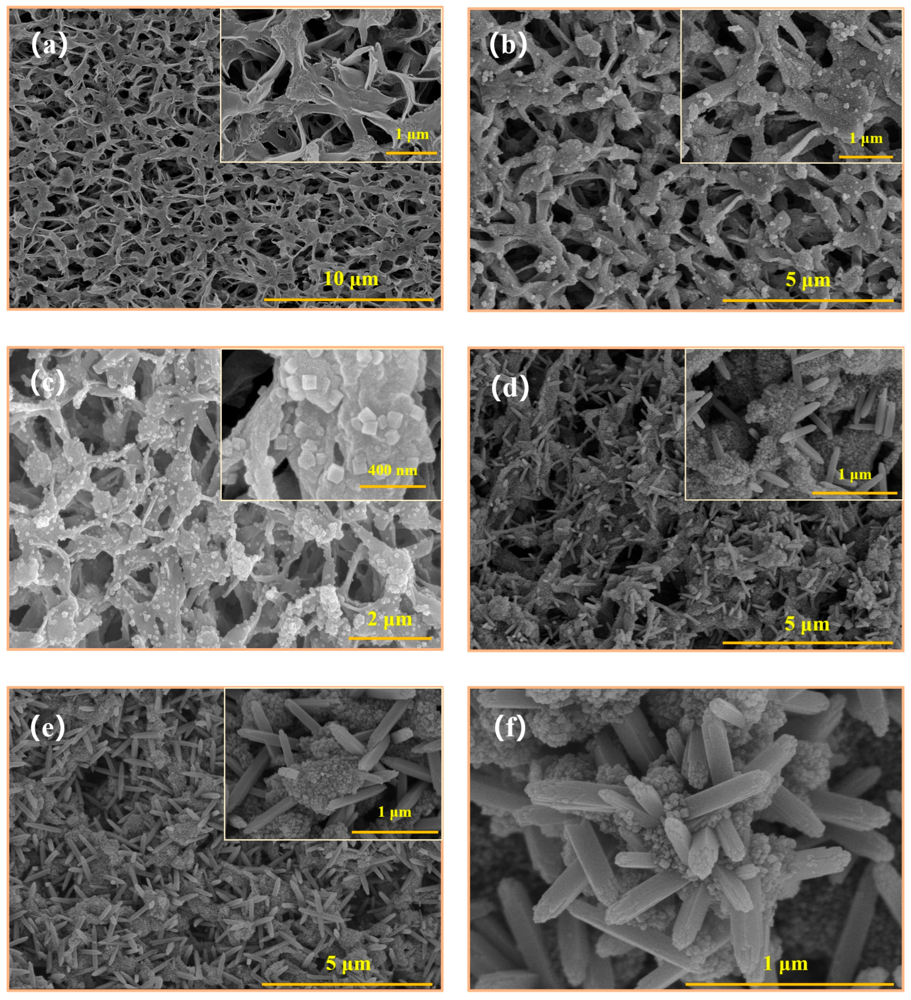
To investigate the effects of the modification process on the membrane surface and cross-section, morphology structure was characterized by SEM. The SEM surface images of pristine membrane and composite membranes are shown in Figure 2. As observed in the figure, significant morphology changes of membrane surface have occurred after modification. Before modification, the pristine membrane consisted of inter-connected polymer chains derived from the semi-crystalline PVDF, demonstrating porous structure. In Figure 2b, “white” granular substances emerged on the membrane surface which were the products of dopamine polymerization. In the Tris-HCl buffer solution with a pH of 8.50, dopamine hydrochloride underwent self-polymerization in an oxygen environment to form polydopamine (PDA). After modification, “cubic” clusters, nano-columns and “sunflower”-like structures were exhibited on the F-TiO2@PVDF membrane surface uniformly, produced by the hydrothermal reaction of butyl titanate solution in a high-pressure reactor. TiO2 was created and loaded on the PDA-modified membrane surface and regarded as the seed crystal to grow into different shapes of crystals. Under high-pressure hydrothermal conditions, butyl titanate was first hydrolyzed into Ti(OH)4 and then dehydrated to generate TiO2 [38,39]. TiO2 was connected with the hydroxyl groups of PDA via hydrogen bonds and continued to grow. When the hydrothermal reaction time was short, TiO2 crystal growth was limited to “cubic” shaped particles distributed on the membrane surface evenly, as presented in Figure 2c. As the hydrothermal reaction time increased, TiO2 crystals continued to grow on the “cubic” particles, with the edges gradually developing into nanocolumns, while the central region remained granular due to spatial constraints, resulting in rough morphology resembling a “sunflower” on the surface, as shown in Figure 2e. The “sunflower-like” structure consisted of cubic nanoclusters and nanopillars, with nanoclusters surrounded by nanopillars. The “sunflower” disk structure was beneficial to the construction of re-entrant morphology on the composite membrane surface, thereby enhancing its omniphobic property. However, as the hydrothermal reaction time was further increased, the particles in the center of the sunflower disk gradually grew into nanocolumns and columnar aggregates, leading to the membrane surface being covered with TiO2 crystals, as demonstrated in Figure 2f. These aggregates blocked membrane pores completely, therefore increasing mass transfer resistance in the MD process.
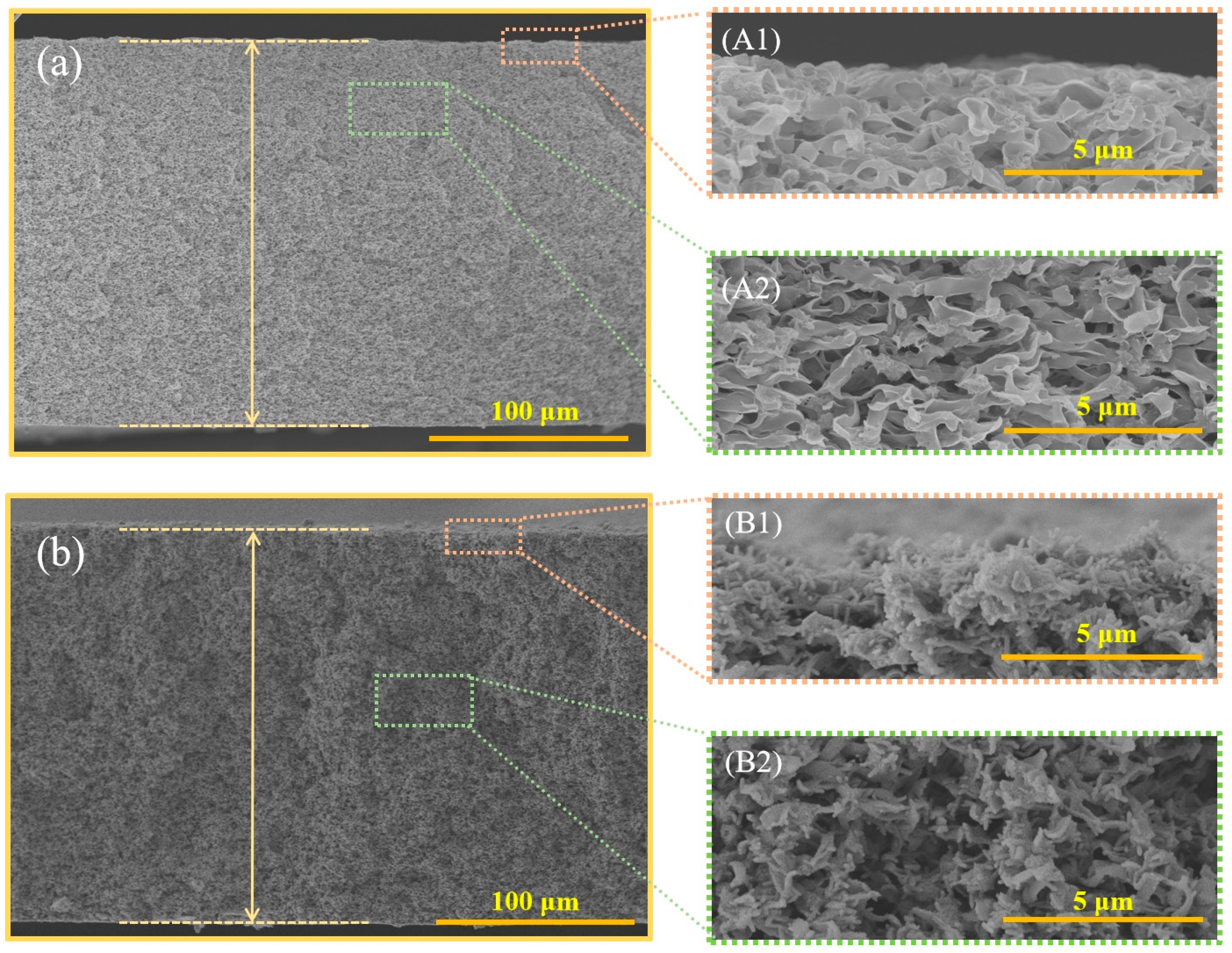
To investigate the impact of the modification process on the internal structure of membrane pores, cross-sectional morphologies were observed and compared before and after modification. SEM cross-section images of pristine membrane and F-TiO2@PVDF composite membrane are depicted in Figure 3. It can be seen that the composite membrane and the pristine membrane tend to stay the same for cross-sectional structures, still composed of sponge-like pores. After modification, the pore morphology of the composite membrane remained basically unchanged, as shown in the magnified images of Figure 3A2,B2. TiO2 nanocolumns were found in the surface layer and internal cross-section of the F-TiO2@PVDF membrane, as displayed in Figure 3B1,B2. TiO2 crystals grew in situ throughout the entire cross-section, indicating that material modification had occurred within membrane pores. Additionally, the thickness of pristine and composite membranes could be estimated by the scale in the bottom right corner of images. The pristine PVDF membrane thickness is 194.5 ± 2.5 μm, and the F-TiO2@PVDF membrane thickness is 195.5 ± 1.5 μm approximately. Therefore, the membrane thickness increases by 1.0 μm after modification and the effect of in situ growth modification on membrane thickness is negligible.

3.2. Membrane Chemical Composition

To confirm the TiO2 modification on the composite membrane, chemical compositions of pristine and composite membranes were characterized by analytical methods such as XRD, ATR-FTIR and XPS.
The crystal structure of the modified composite membrane was characterized using the XRD spectra, as presented in Figure 4. It can be observed that new diffraction peaks (2θ) appear at 25.3°, 37.8°, 48.1°, 54.3° and 55.2°, corresponding to the (101), (004), (200), (105) and (211) planes of TiO2 crystals. All diffraction peaks were in accordance with the standard spectrum of TiO2 (JCPDS NO. 21-1272 and JCPDS 01-077-0443) [40,41,42], indicating that TiO2 had been successfully incorporated into the composite membrane. Functional groups such as hydroxyl and imine were introduced on the membrane surface by PDA polymerization and TiO2 connects with these hydrophilic groups via hydrogen bonds. With the increase in the hydrothermal reaction time, nanoparticle and nanocolumnar clusters were generated under the growth of TiO2 crystal seeds.
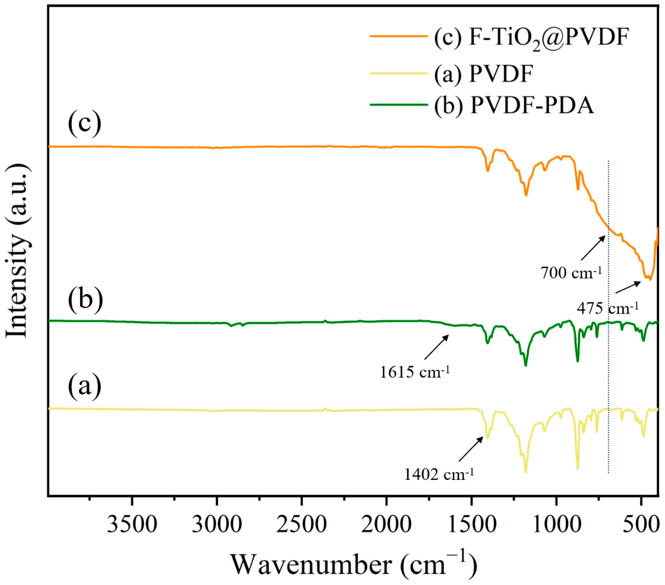
The ATR-FTIR spectra of pristine PVDF membrane, PVDF-PDA membrane and F-TiO2@PVDF membrane are presented in Figure 5. As can be observed, a new broad absorption peak appeared at 1600 cm−1 and 1615 cm−1, which originated from the bending and stretching vibrations of the N-H covalent bonds among PDA molecules and the C=C covalent bonds on the benzene ring. The absorption peak at 1402 cm−1 indicated the bending vibration of C-H covalent bonds [43]. As for the F-TiO2@PVDF composite membrane, the absorption peak intensity of the C-H covalent bond decreased, ascribed to the growth of TiO2 on the membrane surface. Furthermore, new absorption bands at 700 cm−1 and 475 cm−1 are assigned to the stretching vibration of the Ti-O covalent bond [44], manifesting that TiO2 had been successfully integrated onto the F-TiO2@PVDF composite membrane.
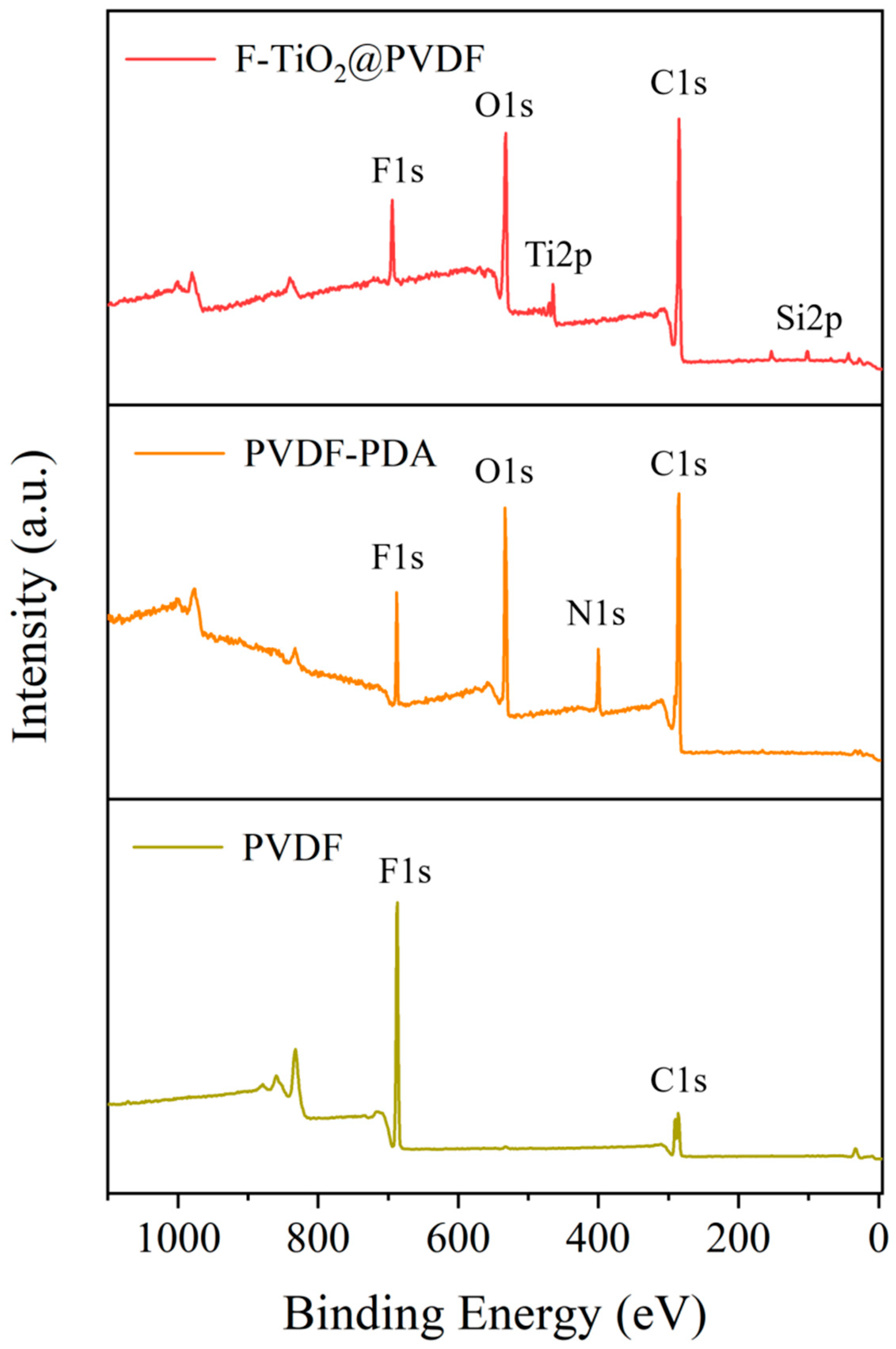
XPS was utilized to further characterize the elemental composition and chemical composition of the membrane surface. The XPS spectra of pristine PVDF membrane, PVDF-PDA membrane and F-TiO2@PVDF membrane are presented in Figure 6. From the XPS full spectra of all membranes, it can be shown that N 1s and O 1s peaks were brought in the PVDF-PDA membrane, and Ti 2p, O 1s and Si 2p peaks are introduced into the F-TiO2@PVDF membrane. These were attributed to PDA polymerization, the formation of TiO2 nanoparticle clusters and nanocolumns and the graft modification of fluorosilane for nano-oxides on the membrane surface. Nevertheless, the intensity of N 1s peak was extremely weak on the F-TiO2@PVDF membrane surface. The penetration depth of the X-rays is less than 10 nm, so they are unable to reach the PDA coating covered with TiO2, resulting in weak N 1s signals [45].

3.3. Membrane Wettability and Structural Parameter

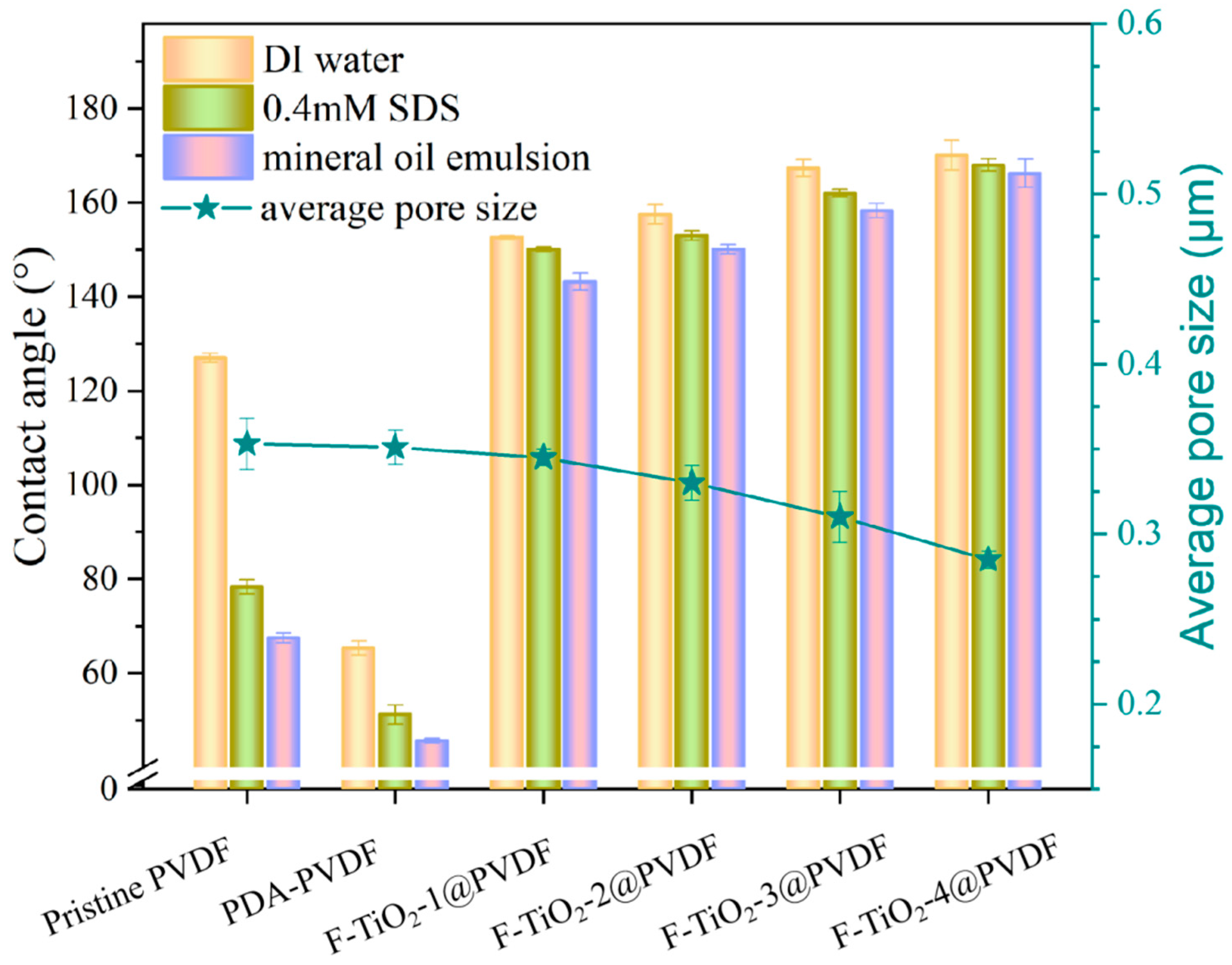
The wetting behavior of the membrane is critical to its anti-wetting and anti-fouling performance in membrane distillation. The wettability of the membrane surface was characterized by measuring contact angles of droplets and monitoring the state of the droplets on the membrane surface. Contact angles (CAs) of the membrane surface were measured with various liquids at room temperature, such as DI water, 1 M NaCl solution with 0.4 mM SDS and 1 M NaCl with 0.2% v/v mineral oil emulsion, as shown in Figure 7. It was illustrated that CAs of the pristine PVDF membrane towards DI water, 0.4 mM SDS solution and 0.2% v/v mineral oil emulsion are 127.0 ± 1.0°, 78.3 ± 1.5° and 67.5 ± 1.2°, respectively. This was attributed to the weak hydrophobic and oleophilic nature of PVDF. The SDS solution and the mineral oil emulsion possess lower surface tension and enable droplets to adsorb onto the membrane surface easily, thereby reducing the CAs of droplets and exhibiting a lyophilic state. After PDA decoration, hydrophilic groups such as amino and hydroxyl were grafted on the membrane surface. The CAs of the PDA-PVDF membrane towards DI water, 0.4 mM SDS solution and 0.2% v/v mineral oil emulsion were 65.3 ± 1.5°, 51.2 ± 2.0° and 45.6 ± 0.5°, respectively. The PDA-PVDF membrane surface exhibited hydrophilicity. In situ growth of cubic nanoclusters and nanocolumns contributed to enhancing surface roughness, and fluorinated silane modification reduced the solid surface energy of the membrane surface, promoting the repulsion of droplets from the F-TiO2@PVDF membrane surface.
Compared to the pristine PVDF membrane, the F-TiO2-3@PVDF membrane displayed higher CAs towards DI water (~167.3°), 0.4 mM SDS solution (~162.0°) and 0.2% v/v mineral oil emulsion (~158.5°), respectively. The “sunflower”-like micro-nano composite morphology and the stacked nanocolumn morphology in an interlaced pattern are beneficial for constructing the re-entrant structure. The low-surface-energy carbon fluorine long chains from fluorosilane were introduced on the membrane surface. The F-TiO2-3@PVDF composite membrane exhibited super-repellence to various droplets, a property derived from its outstanding omniphobic characteristic. Furthermore, a 10° incline angle was established between the test bench and the horizontal plane, and the water droplet is dripped on the membrane sample. It was observed that droplets can bounce and roll off the F-TiO2-3@PVDF membrane surface, while droplets only showed a downward trend and remained stationary at the original position. It implied that the F-TiO2-3@PVDF composite membrane demonstrated lyophobic properties.
A structural membrane parameter such as pore size will affect the permeate flux in the MD test. The average pore sizes of pristine PVDF and modified membranes are also shown in Figure 7. It can be seen that the modification process has an effect on the average pore size. In particular, the average pore size of the pristine PVDF membrane was 0.353 ± 0.015 μm, and the average pore size of the F-TiO2-3@PVDF membrane was 0.31 ± 0.012 μm. The average pore size of F-TiO2@PVDF composite membrane is lower than that of pristine PVDF membrane and decreased gradually as hydrothermal reaction time increased. Composite membranes were conferred with omniphobic characteristics owing to the modification layer. However, with the in situ growth of TiO2 on the surface, “cubic” nanoparticles transformed into cylinders and they intersected and overlapped each other, thus covering the membrane pores. Additionally, TiO2 crystals also occurred in the membrane pores, and the pore space was occupied partially.

3.4. Membrane Distillation Fouling Test

The membrane wettability depends on geometric structure and chemical composition. The construction of microscale and nanoscale rough topographies and the introduction of low-surface-energy materials are conducive to omniphobic characteristics. The sunflower-like nano-composite structure was built via in situ growth of cubic clusters and nano-columns, presenting diverse re-entrant morphology on the membrane surface. When a droplet was contacted with the membrane surface, air cavities filled in the re-entrant structure and low-surface-energy chemical characteristics provided repulsive forces to the droplet, making it difficult to stay on the membrane surface. The droplets were in the thermodynamically metastable Cassie–Baxter state. The apparent contact area consisted of a solid–liquid contact area and a solid–air contact area. According to the Cassie–Baxter equation, the apparent contact angle increased with the decline of the proportion of the liquid–solid area to the total area [46,47,48]. As an additional barrier, air pockets from the hierarchical structure strengthened the resistance to liquids entering the membrane pores, enhancing antiwetting performance. This provided potential possibilities for membrane distillation to deal with the feed system containing surfactants and oil contaminants. The multi-level re-entrant structure played a crucial role in maintaining the metastable Cassie–Baxter thermodynamic state and realizing omniphobic peculiarity, which can alleviate membrane fouling and the membrane wetting.
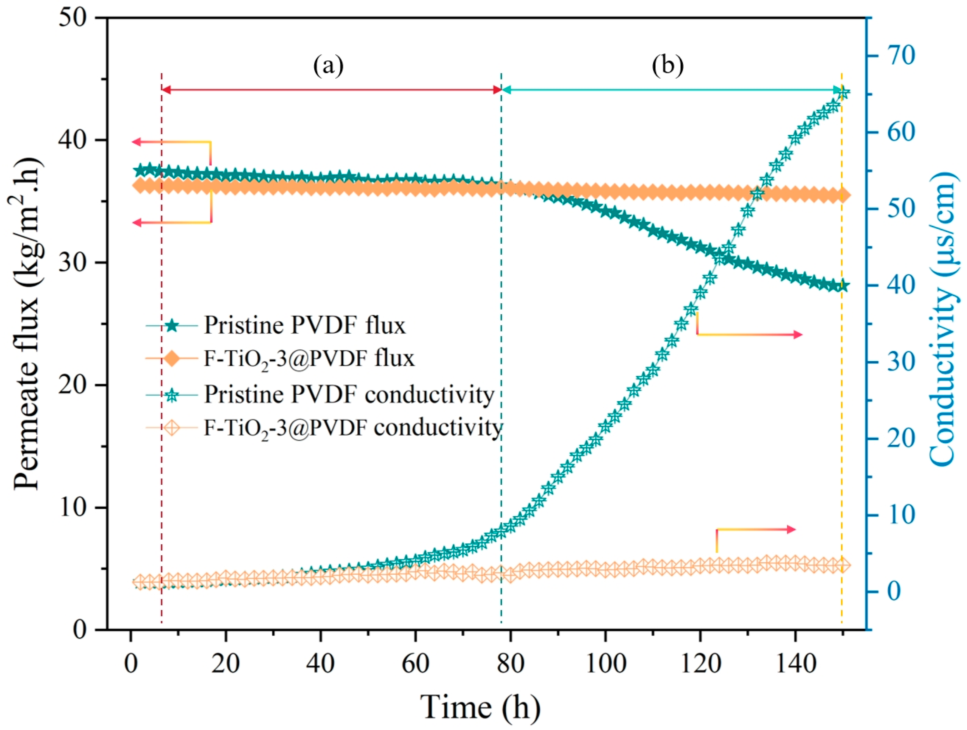
In the DCMD process, the anti-fouling performance of the membrane determines separation performance and service life. Based on the results of surface morphology analysis and structural parameter testing, F-TiO2-3@PVDF was selected as the prime means to assess anti-fouling performance and compared with the pristine PVDF membrane. To investigate the membrane’s ability to repel inorganic salts and organic compounds, different contaminant components were used as the feed and concentrated continuously during the experiment. The permeate fluxes and conductivities for pristine PVDF membrane and F-TiO2-3@PVDF membrane with mixed salt and organic solutions as a function of time are presented in Figure 8. Initially, DI water was used as the feed to test the DCMD system for 6 h. Subsequently, the feed solution was replaced by 35 g/L NaCl solution and tested for 72 h continuously. It was found that the permeate flux of the F-TiO2-3@PVDF membrane (~36.3 kg/m2·h) was lower than that of the pristine PVDF membrane (~37.5 kg/m2·h) for DI water. After the feed solution was replaced with salt solution, the permeate flux of the F-TiO2-3@PVDF membrane remained stable, with the permeate conductivity approaching that of DI water. However, the permeate flux of the pristine PVDF membrane decreased by approximately 3%. Pure NaCl solution had no effect on the composite membrane and only a small impact on the pristine PVDF membrane. Next, 1.26 g/L CaCl2, 1.61 g/L MgSO4 and 10 mg/L HA were added to the feed, and the system was operated and concentrated for 72 h. It was observed that the permeate flux of the pristine PVDF membrane continued to decrease until reaching 74.9% of the initial value, while that of the F-TiO2-3@PVDF membrane remained almost steady. The permeate conductivity of the pristine PVDF membrane increased sharply to 65.2 μs/cm, while the permeate conductivity of the F-TiO2-3@PVDF membrane was still close to that of DI water. The introduction of Ca2+ and SO42− was liable to form the CaSO4 scale, and HA easily adhered to the hydrophobic membrane due to strong hydrophobic–hydrophobic interactions with the surface of the pristine PVDF membrane. The synergistic effects of inorganic precipitation and organic contamination intensified the membrane fouling and wetting, causing partial membrane pore blockage and leading to the decrease of the permeate flux and the increase of the conductivity. In contrast, for the F-TiO2-3@PVDF membrane it was difficult for inorganic salts and organic pollutants to adsorb and stay on the sunflower-like re-entrant morphology surface with low surface energy. This is due to the air pockets provided by the concave structure, reducing the actual liquid–solid contact area and enhancing the repulsion toward liquids. Therefore, the omniphobic composite membrane exhibited stable permeate flux and conductivity.
The foulants, including inorganic ions, organic compounds, surfactants and oil emulsions, presented the interaction with the membrane surface, resulting in deterioration of membrane performance to different extents. There were strong attractive effects between terminal groups, with positive charges of organic compounds and surfactants, as well as oil molecules and the hydrophobic membrane surface with negative charges. Furthermore, hydrophobic–hydrophobic interactions between foulants and the hydrophobic membrane surface strengthened membrane fouling and wetting.
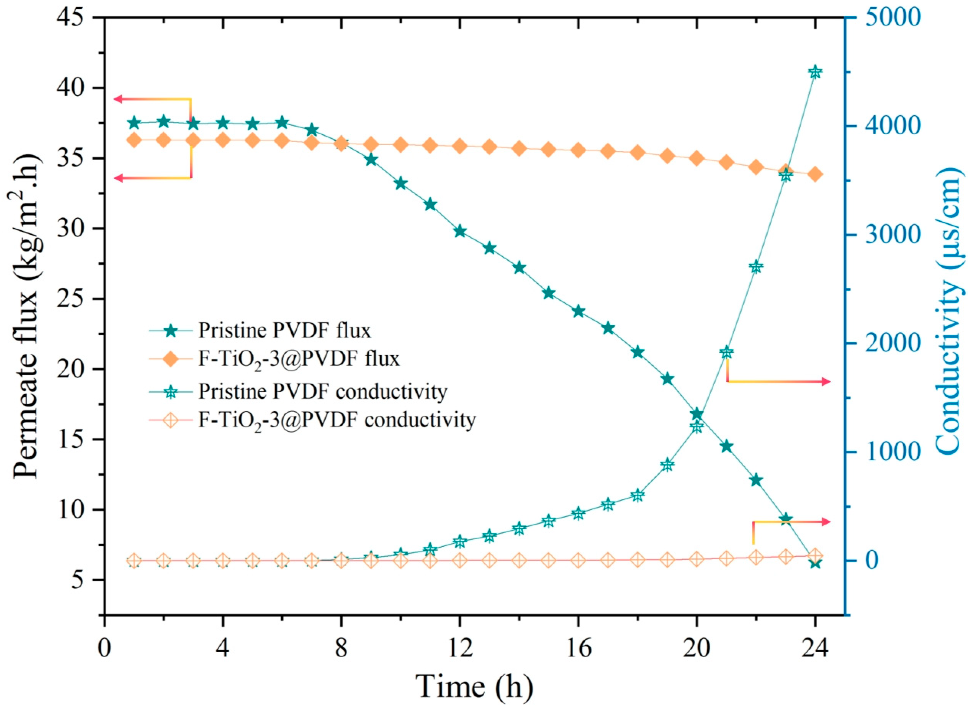
To further explore the anti-wetting and anti-fouling performance of the composite membrane, surfactant and oil emulsion were added to simulated seawater for membrane distillation and the test results are shown in Figure 9 and Figure 10. In the first 6 h, DI water was used as the feed for a stable test. Subsequently, the simulated sea water (35 g/L NaCl) replaced DI water as the feed, and CaCl2, MgSO4 and HA were added to the feed, followed by 0.4 mM SDS for continuous testing. As shown in Figure 9, the permeate flux of the pristine PVDF membrane declined heavily from 37.5 kg/m2·h to 6.25 kg/m2·h, and the permeate conductivity rapidly increased to 4500 μs/cm. On the contrary, the F-TiO2-3@PVDF membrane exhibited stable permeate flux and conductivity relatively, with a flux decline rate of only 6.7%. It was closely related to the unique morphology structure of the composite membrane surface. The in situ growth of cubic clusters and the nano-column structure on the F-TiO2-3@PVDF membrane, along with the grafting of low-surface-energy fluorosilane, reduced the affinity between the salt solution system and the composite membrane surface. This would weaken contamination and wetting on the composite membrane, demonstrating excellent anti-wetting and anti-fouling performance.
Significant changes were caused by adding oil emulsions to simulated seawater for the pristine PVDF membrane in DCMD tests. In Figure 10, after stable operation for 3 h with DI water as the feed, NaCl, CaCl2, MgSO4, HA and mineral oil emulsion were gradually added to form the feed containing inorganic salts, organic matter and oil pollutants. It can be seen that the permeate flux of the pristine PVDF membrane had completely dropped to 0, while that of the F-TiO2-3@PVDF membrane only showed a slight decrease by approximately 11.4%, after the system continued for an extra 8 h. The permeate conductivity was less than 30 μs/cm and the calculated salt rejection rate was close to the theoretical value of 100%. This indicated that the pristine PVDF membrane surface had been completely covered with contaminants and the membrane pores were blocked. Conversely, the composite membrane maintained normal membrane distillation, attributed to the surface-constructed nano-composite structure and the introduction of low surface energy, which made it difficult for pollutants to adhere to the surface, thereby enhancing anti-fouling and anti-wetting performance.

4. Conclusions

The F-TiO2@PVDF membrane with omniphobic characteristics was prepared by a simple and facile strategy, namely constructing micro/nano-composite structures similar to sunflower morphology with hydrothermal synthesis, followed by fluorosilane treatment for membrane surfaces. The re-entrant structures resulting from TiO2 nanoparticles, cubic clusters and columns and the omniphobic feature were imparted to the composite membrane. A series of characterizations of membrane morphology and surface analysis, as well as membrane wettability and intrinsic properties were performed for pristine and composite membranes. Additionally, sequential DCMD experiments were conducted to investigate the anti-wetting and anti-fouling performance of pristine and composite membranes systematically, with different contaminants as the feed. The results showed that TiO2 crystals were in situ grown into nanoclusters and nanopillars, forming a sunflower-like micro-nanocomposite hierarchical morphology. The surface analysis showed that the diffraction absorption peaks of TiO2 crystals, as well as Ti, O and Si elements appeared on the surface, indicating that TiO2 and fluorosilanes were successfully modified in the composite membrane. The F-TiO2-3@PVDF composite membrane exhibited superlyophobic characteristic with surface contact angles of 167.3°, 162.0° and 158.5° towards DI water, 0.4 mM SDS solution and 0.2% v/v mineral oil emulsion, respectively. Compared to the pristine PVDF membrane, the composite membrane presented relatively stable permeate flux, with a nearly 100% salt rejection rate for the feed containing inorganic salts, organic compounds, surfactants and oil emulsion. Biomimetical omniphobic composite membranes modified by TiO2 nanoparticles can potentially deal with brine wastewater and achieve zero liquid discharge.

Author Contributions

W.Z.: conceptualization, methodology, formal analysis, investigation, resources, data curation, writing—original draft and visualization. X.Z.: supervision and writing—review and editing. B.L.: methodology, validation, writing—review and editing and supervision. B.H.: writing—review and editing. L.S.: resources, project administration and validation. Y.M.: project administration and funding acquisition. H.G.: writing—review and editing and supervision. All authors have read and agreed to the published version of the manuscript.

Funding

This research was funded by the Science and Technology Project of State Grid Corporation of China, Grant NO. 5700-202335249A-1-1-ZN.

Data Availability Statement

All data are contained within the article.

Conflicts of Interest

The authors declare that they have no known competing financial interest or personal relationships that could have appeared to influence the work reported in this paper.

References

  1. Shannon, M.A.; Bohn, P.W.; Elimelech, M.; Georgiadis, J.G.; Marinas, B.J.; Mayes, A.M. Science and technology for water purification in the coming decades. Nature 2018, 452, 301–310. [Google Scholar] [CrossRef]
  2. Gude, V.G.; Nirmalakhandan, N.; Deng, S.G. Renewable and sustainable approaches for desalination. Renew. Sustain. Energy Rev. 2010, 14, 2641–2654. [Google Scholar] [CrossRef]
  3. Ogunniyi, E.O.; Richards, B.S. Renewable energy powered membrane technology: Electro-hydraulic control system design for managing pump shutdowns in a photovoltaic-membrane water desalination system. Desalination 2025, 608, 118784–118800. [Google Scholar] [CrossRef]
  4. Jones, E.; Qadir, M.; Vliet, M.T.; Smakhtin, V.; Kang, S. The state of desalination and brine production: A global outlook. Sci. Total Environ. 2019, 657, 1343–1356. [Google Scholar] [CrossRef]
  5. Ali, A.; Tufa, R.A.; Macedonio, F.; Curcio, E.; Drioli, E. Membrane technology in renewable-energy-driven desalination. Renew. Sustain. Energy Rev. 2018, 81, 1–21. [Google Scholar] [CrossRef]
  6. Grant, S.B.; Saphores, J.D.; Feldman, D.L.; Hamilton, A.J.; Fletcher, T.D.; Cook, P.M.; Stewardson, M.; Sanders, B.F.; Levin, L.A.; Ambrose, R.F.; et al. Taking the “waste” out of “wastewater” for human water security and ecosystem sustainability. Science 2012, 337, 681–686. [Google Scholar] [CrossRef]
  7. Gittins, J.R.; Hemingway, J.R.; Dajka, J.C. How a water-resources crisis highlights social-ecological disconnects. Water Res. 2021, 194, 116937–116941. [Google Scholar] [CrossRef]
  8. Duckett, D.; Troldborg, M.; Hendry, S.; Cousin, H. Making waves: Promoting municipal water reuse without a prevailing scarcity driver. Water Res. 2024, 249, 120965–120970. [Google Scholar] [CrossRef]
  9. Deshmukh, A.; Boo, C.; Karanikola, V.; Lin, S.H.; Straub, A.P.; Tong, T.Z.; Warsinger, D.M.; Elimelech, M. Membrane distillation at the water-energy nexus: Limits, opportunities, and challenges. Energy Environ. Sci. 2018, 11, 1177–1196. [Google Scholar] [CrossRef]
  10. Gude, V.G. Desalination and sustainability—An appraisal and current perspective. Water Res. 2016, 89, 87–106. [Google Scholar] [CrossRef]
  11. Criscuoli, A.; Macedonio, F.; Brunetti, A.; Tocci, E.; Drioli, E. Impact of Membrane Engineering on the Process Engineering Progresses: Towards a Sustainable Development. Chem. Eng. Process. Process Intensif. 2023, 189, 109385. [Google Scholar] [CrossRef]
  12. Buggenhout, S.V.; Verbeke, R.; Davenport, D.M.; Vankelecom, I.F. Drying polymer membranes for preservation: A review. J. Membr. Sci. 2025, 731, 124190–124207. [Google Scholar] [CrossRef]
  13. Alkhudhiri, A.; Darwish, N.; Hilal, N. Membrane distillation: A comprehensive review. Desalination 2012, 287, 2–18. [Google Scholar] [CrossRef]
  14. Lawson, K.W.; Lloyd, D.R. Membrane distillation. J. Membr. Sci. 1997, 124, 1–25. [Google Scholar] [CrossRef]
  15. Khayet, M. Membranes and theoretical modeling of membrane distillation: A review. Adv. Colloid Interface Sci. 2011, 164, 56–88. [Google Scholar] [CrossRef]
  16. Drioli, E.; Ali, A.; Macedonio, F. Membrane distillation: Recent developments and Perspectives. Desalination 2015, 356, 56–84. [Google Scholar] [CrossRef]
  17. El-Bourawi, M.S.; Ding, Z.; Ma, R.; Khayet, M. A framework for better understanding membrane distillation separation process. J. Membr. Sci. 2006, 285, 4–29. [Google Scholar] [CrossRef]
  18. Tong, T.; Elimelech, M. The global rise of zero liquid discharge for wastewater management: Drivers, technologies, and future directions. Environ. Sci. Technol. 2016, 50, 6846–6855. [Google Scholar] [CrossRef]
  19. Frédette, C.; Comeau, Y.; Brisson, J. Design of a zero liquid discharge leachate treatment system using an evapotranspiration willow bed. Water Res. 2022, 209, 117950–117959. [Google Scholar] [CrossRef]
  20. Wang, P.; Deng, H.; Yao, J.; Cheng, W.; Wu, C.; Zhang, T.; Ma, J.; Wang, W. Unraveling the intricate fouling behaviors of landfill leachate components during membrane distillation concentration toward zero liquid discharge. J. Membr. Sci. 2024, 703, 122851–122861. [Google Scholar] [CrossRef]
  21. Yao, M.W.; Tijing, L.D.; Naidu, G.; Kim, S.H.; Matsuyama, H.; Fane, A.G.; Shon, H.K. A review of membrane wettability for the treatment of saline water deploying membrane distillation. Desalination 2020, 479, 114312–114333. [Google Scholar] [CrossRef]
  22. Naidu, G.; Tijing, L.; Johir, M.; Shon, H.; Vigneswaran, S. Hybrid membrane distillation: Resource, nutrient and energy recovery. J. Membr. Sci. 2020, 599, 117832–117852. [Google Scholar] [CrossRef]
  23. Gontarek-Castro, E.; Castro-Muñoz, R. How to make membrane distillation greener: A review of environmentally friendly and sustainable aspects. Green Chem. 2024, 26, 164–185. [Google Scholar] [CrossRef]
  24. González, D.; Amigo, J.; Suárez, F. Membrane distillation: Perspectives for sustainable and improved desalination. Renew. Sustain. Energy Rev. 2017, 80, 238–259. [Google Scholar] [CrossRef]
  25. Yu, S.; Zhao, Q.; Zhu, J.; Gong, G.; Hu, Y. Incorporating TiO2 nanocages into electrospun nanofibrous membrane for efficient and anti-fouling membrane distillation. J. Membr. Sci. 2024, 698, 122614–122623. [Google Scholar] [CrossRef]
  26. Chang, H.; Zhu, Y.; Huang, L.; Yan, Z.; Qu, F.; Liang, H. Mineral scaling induced membrane wetting in membrane distillation for water treatment: Fundamental mechanism and mitigation strategies. Water Res. 2023, 247, 120807–120828. [Google Scholar] [CrossRef]
  27. Siyal, M.I.; Lee, C.K.; Park, C.; Khan, A.A.; Kim, J.O. A review of membrane development in membrane distillation for emulsified industrial or shale gas wastewater treatments with feed containing hybrid impurities. J. Environ. Manag. 2019, 243, 45–66. [Google Scholar] [CrossRef]
  28. Abid, M.B. Advancements in Omniphobic membranes: Properties, fabrication techniques, and applications in membrane distillation. Desalination Water Treat. 2025, 322, 101214–101225. [Google Scholar] [CrossRef]
  29. Li, J.; Ren, L.F.; Huang, M.; Yang, J.; Shao, J.; He, Y. Facile preparation of omniphobic PDTS-ZnO-PVDF membrane with excellent anti-wetting property in direct contact membrane distillation (DCMD). J. Membr. Sci. 2022, 650, 120404–120415. [Google Scholar] [CrossRef]
  30. Feng, H.; Li, H.; Li, M.; Zhang, X. Construction of omniphobic PVDF membranes for membrane distillation: Investigating the role of dimension, morphology, and coating technology of silica nanoparticles. Desalination 2022, 525, 115498. [Google Scholar] [CrossRef]
  31. Zhu, Z.; Tan, G.; Lei, D.; Yang, Q.; Tan, X.; Liang, N.; Ma, D. Omniphobic membrane with process optimization for advancing flux and durability toward concentrating reverse-osmosis concentrated seawater with membrane distillation. J. Membr. Sci. 2021, 639, 119763–119772. [Google Scholar] [CrossRef]
  32. Liao, X.; Goh, K.; Liao, Y.; Wang, R.; Razaqpur, A.G. Bio-inspired super liquid-repellent membranes for membrane distillation: Mechanisms, fabrications and applications. Adv. Colloid. Interface Sci. 2021, 297, 102547–102573. [Google Scholar] [CrossRef]
  33. Tolan, D.; El-Sawaf, A.; Ahmed, A.S.A.; Nassar, A.; Mohamed, N.M.; Alhindawy, I.G.; Elshehy, E.A.; Utgikar, V. Enhanced photocatalytic activity of (In–Sr–P) tridoped TiO2/Bi2O3 composite loaded on mesoporous carbon: A facile sol-hydrothermal synthesis approach. Mater. Chem. Phys. 2024, 322, 129570–129581. [Google Scholar] [CrossRef]
  34. Gupta, T.; Samriti; Cho, J.; Prakash, J. Hydrothermal synthesis of TiO2 nanorods: Formation chemistry, growth mechanism, and tailoring of surface properties for photocatalytic activities. Mater. Today Chem. 2021, 20, 100428–100467. [Google Scholar] [CrossRef]
  35. Zhang, W.; Li, Y.; Liu, J.; Li, B.; Wang, S. Fabrication of hierarchical poly (vinylidene fluoride) micro/nano-composite membrane with anti-fouling property for membrane distillation. J. Membr. Sci. 2017, 535, 258–267. [Google Scholar] [CrossRef]
  36. Zhang, W.; Lu, Y.; Liu, J.; Li, X.; Li, B.; Wang, S. Preparation of re-entrant and anti-fouling PVDF composite membrane with omniphobicity for membrane distillation. J. Membr. Sci. 2020, 595, 117563–117576. [Google Scholar] [CrossRef]
  37. Zhang, W.; Hu, B.; Wang, Z.; Li, B. Fabrication of omniphobic PVDF composite membrane with dual-scale hierarchical structure via chemical bonding for robust membrane distillation. J. Membr. Sci. 2021, 622, 119038–119052. [Google Scholar] [CrossRef]
  38. Tong, Y.; Wu, Y.; Xu, Z.; Luo, L.; Jia, R.; Han, R. Hydrolysis co-deposition of bio-inspired hybrid hydrophilic network antifouling loose nanofiltration membrane for effective dye/salt separation. J. Membr. Sci. 2024, 694, 122444–122458. [Google Scholar] [CrossRef]
  39. Mameda, N.; Park, H.; Kim, J.; Shah, S.S.; Rahman, S.; Sherugar, P.; Lee, H.; Choo, K.H. Self-assembled electrocatalytic TiO2 nanowire membrane for multifunctional water purification. J. Membr. Sci. 2025, 734, 124422–124434. [Google Scholar] [CrossRef]
  40. Cao, N.; Gu, M.; Gao, M.; Li, C.; Liu, K.; Zhao, X.; Feng, J.; Ren, Y.; Wei, T. A three-layer photocatalyst carbon fibers/TiO2 seed/TiO2 nanorods with high photocatalytic degradation under visible light. Appl. Surf. Sci. 2020, 530, 147289–147295. [Google Scholar] [CrossRef]
  41. Chu, Z.; Qiu, L.; Chen, Y.; Zhuang, Z.; Du, P.; Xiong, J. TiO2-loaded carbon fiber: Microwave hydrothermal synthesis and photocatalytic activity under UV light irradiation. J. Phys. Chem. C 2020, 136, 109138–109144. [Google Scholar] [CrossRef]
  42. Jiang, X.; Duan, Y.; Tian, Y.; Chen, M.; Li, M.; Liu, H.; Yang, W.; Tian, M. Facile one-pot hydrothermal method to prepare Sn(II) and N co-doped TiO2 photocatalyst for water splitting under visible light irradiation. Rare Met. 2022, 41, 406–414. [Google Scholar] [CrossRef]
  43. Maaref, S.; Kantzas, A.; Bryant, S.L. The effect of silanization assisted nanoparticle hydrophobicity on emulsion stability through droplet size diatribution analysis. Chem. Eng. Sci. 2019, 201, 175–190. [Google Scholar] [CrossRef]
  44. Chen, F.; Zhao, L.; Yu, W.; Wang, Y.; Zhang, H.; Guo, L. Dynamic monitoring and regulation of pentachlorophenol photodegradation process by chemiluminescence and TiO2/PDA. J. Hazard. Mater. 2020, 399, 123073–123081. [Google Scholar] [CrossRef]
  45. Boussu, K.; De Baerdemaeker, J.; Dauwe, C.; Weber, M.; Lynn, K.G.; Depla, D.; Aldea, S.; Vankelecom, I.F.; Vandecasteele, C.; Van der Bruggen, B. Physico-chemical characterization of nanofiltration membranes. Chem. Phys. Chem. 2007, 8, 370–379. [Google Scholar] [CrossRef] [PubMed]
  46. Erbil, H.Y.; Cansoy, C.E. Range of applicability of the Wenzel and Cassie-Baxter equations for superhydrophobic surfaces. Langmuir 2009, 25, 14135–14145. [Google Scholar] [CrossRef] [PubMed]
  47. Sun, W.; Li, J.; Qiu, J.; Sun, Y. Biomimetic nano/microfabrication techniques in multi-bioinspired superhydrophobic wood: New insight on theory, design and applications. Surf. Interfaces 2024, 48, 104217–104235. [Google Scholar] [CrossRef]
  48. Bormashenko, E. Why does the Cassie–Baxter equation apply? Colloids Surf. A 2008, 324, 47–50. [Google Scholar] [CrossRef]
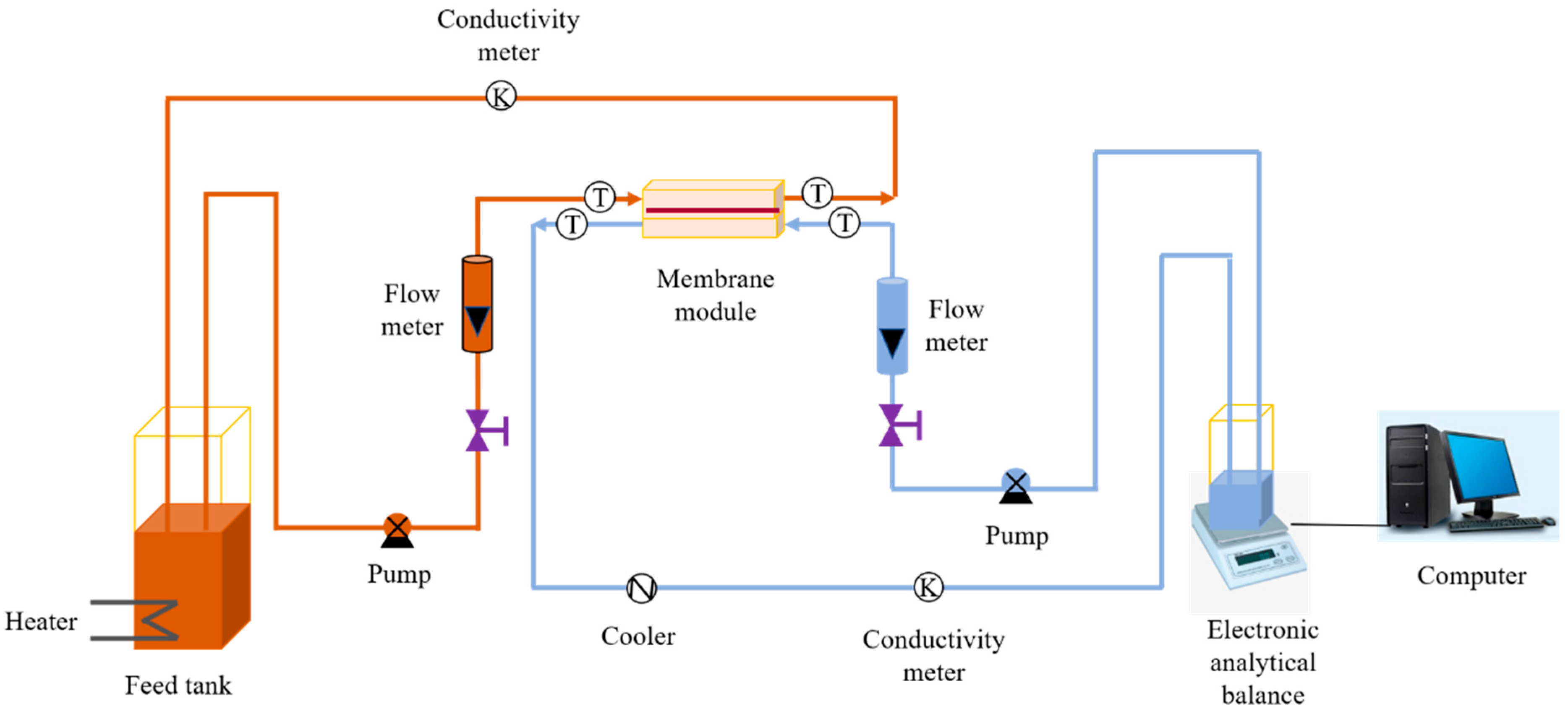
Figure 1. Schematic diagram of the DCMD experimental set-up.
Coatings 15 00965 g001
Figure 2. SEM surface images of pristine membrane and composite membranes: (a) pristine PVDF membrane, (b) PVDF-PDA membrane, (c) F-TiO2@PVDF-1 membrane, (d) F-TiO2@PVDF-2 membrane, (e) F-TiO2@PVDF-3 membrane and (f) F-TiO2@PVDF-4 membrane, the corresponding SEM images at a higher magnification are displayed in the upper-right corner of the graphs.
Coatings 15 00965 g002
Figure 3. SEM cross-section images of pristine and composite membranes: (a,A1,A2) pristine PVDF membrane and (b,B1,B2) F-TiO2@PVDF membrane.
Coatings 15 00965 g003
Figure 4. XRD patterns of PVDF-PDA membrane and TiO2@PVDF membrane.
Coatings 15 00965 g004
Figure 5. ATR-FTIR spectra of original and modified membranes: (a) pristine PVDF membrane, (b) PVDF-PDA membrane and (c) F-TiO2@PVDF membrane.
Coatings 15 00965 g005
Figure 6. XPS full spectra of pristine PVDF membrane, PVDF-PDA membrane and F-TiO2@PVDF membrane.
Coatings 15 00965 g006
Figure 7. Contact angles and average pore sizes of pristine PVDF membranes, PVDF-PDA membranes and F-TiO2@PVDF membranes. Standard deviations were obtained from at least three different measurements.
Coatings 15 00965 g007
Figure 8. Permeate flux and conductivity vary with the operating time for pristine PVDF and F-TiO2-3@PVDF membranes in different feed solutions: (a) 35 g/L NaCl, (b) 35 g/L NaCl, 1.26 g/L CaCl2, 1.61 g/L MgSO4 and 10 mg/L HA.
Coatings 15 00965 g008
Figure 9. Permeate flux and conductivity vary with the operating time for pristine PVDF and F-TiO2-3@PVDF membranes in the feed solution of 35 g/L NaCl, 1.26 g/L CaCl2, 1.61 g/L MgSO4, 10 mg/L HA and 0.4 mM SDS.
Coatings 15 00965 g009
Figure 10. Permeate flux and conductivity vary with the operating time for pristine PVDF and F-TiO2-3@PVDF membranes in the feed solution of 35 g/L NaCl, 1.26 g/L CaCl2, 1.61 g/L MgSO4, 10 mg/L HA and 0.4 mM mineral oil emulsion.
Coatings 15 00965 g010
Table 1. The composition parameters of feed solutions in DCMD tests.
FeedInlet Temperature of the Feed (°C)Inlet Temperature of the Permeate (°C)Feed Velocity (m/s)Permeate Velocity (m/s)
35 g/L NaCl [28,36]~65~15~0.38~0.38
35 g/L NaCl + 1.26 g/L CaCl2 + 1.61 g/L MgSO4 + 10 mg/L HA [28,36]
35 g/L NaCl + 1.26 g/L CaCl2 + 1.61 g/L MgSO4 + 10 mg/L HA + 0.4 mM SDS [37]
35 g/L NaCl + 1.26 g/L CaCl2 + 1.61 g/L MgSO4 + 10 mg/L HA + 0.20% mineral oil emulsion [37]
Disclaimer/Publisher’s Note: The statements, opinions and data contained in all publications are solely those of the individual author(s) and contributor(s) and not of MDPI and/or the editor(s). MDPI and/or the editor(s) disclaim responsibility for any injury to people or property resulting from any ideas, methods, instructions or products referred to in the content.