Abstract
With rising global temperatures, roads in the permafrost regions of the Qinghai–Tibet Plateau are exhibiting issues such as subsidence, water accumulation alongside the roads and in their foundations, and ongoing permafrost degradation. Among these issues, water accumulation has emerged as a prominent challenge in road management. In this study, sodium-based-bentonite-modified cementitious waterproof grouting materials were prepared and utilized as functional barrier layers. The rheological properties, mechanical strength, flowability, and setting time of the materials were tested under different sodium bentonite dosages. The feasibility of the application of these materials was evaluated, accounting for the evolution of pressure, flow rate, and diffusion distance of permafrost subgrades over different time scales when the materials were applied as functional barrier layers. The results indicate that, when used as a functional barrier layer, the modified cement-based grouting material exhibits a fluidity that meets the upper limit of grouting requirements, with a controllable setting time. Both compressive strength and apparent viscosity rise with the addition of sodium-based bentonite (Na-bentonite). Notably, an appropriate viscosity range of 0.35–0.50 Pa·s was found to effectively resist groundwater erosion while satisfying the critical performance requirements for grouting applications, demonstrating excellent applicability. In the field grouting test, the effects of grouting pressure and flow rate over different time scales on soil cracking, spreading distance, and the crack-filling process were further analyzed. Based on these findings, a technical solution using a new type of subgrade treatment material (functional barrier layer) was proposed, providing a reference for related theoretical research and engineering practice.
1. Introduction
In recent years, the energy balance of the active layers in permafrost regions has been altered by climate change and human activities [1,2,3]. Concurrently, increased rainfall has led to a rise in surface water, further triggering abnormal fluctuations in underground permafrost and soil moisture. This energy imbalance, coupled with hydrological disturbances, has directly compromised the original stability of the permafrost–soil system. Excessive water infiltration and intensified freeze–thaw cycles have formed a vicious cycle, causing the overlying roads to suffer from thermal thawing settlement and soil wet subsidence, resulting in cracks and subsidence that seriously threaten traffic safety. To address such water-induced damage, the key is to block the pathways of disorderly water migration and abnormal heat exchange; functional barrier layers can fulfill this critical role. Specifically, barrier layers constructed using grouting technology, leveraging the hydrophobic and impermeable properties imparted by modified coating, can significantly reduce surface water infiltration. Additionally, the optimized thermal insulation function of the coating can effectively inhibit thermal disturbance in permafrost. Relevant studies have confirmed the effectiveness of coating technologies in enhancing the hydrothermal control performance of barrier layers [4,5]. This barrier design, which focuses on coating technology, thus provides a precise and targeted solution for mitigating road damage in permafrost areas.
Water damage is a prevalent issue in road engineering. To address such problems, various solutions have been developed, among which grouting curtain technology distinguishes itself due to its convenience, cost-effectiveness, and durability. Widely applied in foundation and underground engineering, its dual functions of water control and structural reinforcement are highly aligned with the core requirements of barrier layers in permafrost regions. It is worth noting that, when grouting curtain technology is combined with coating technology, its adaptability in permafrost regions can be further enhanced. Using sodium-based bentonite as the base material, coating technology is employed to endow its surface with special functions. This approach leverages the physical water-blocking properties of bentonite, which swells when exposed to water to form a dense gel, while also enhancing its resistance to freeze–thaw cycles and thermal disturbance suppression through coating modification. This thus provides a more specific technical path for the application of coating technology in the prevention and control of water damage in permafrost areas. Wen et al. [6] studied the effect of a cationic polymer on sodium bentonite; they mainly discussed the change that they observed in the cement paste flocculation measurement. They found that the ratio of the size of flocs was high, and the proportion decreased with the shear rate, and they showed that the cationic polymer would inhibit the formation of flocculant in the cement slurry of sodium bentonite. Liu et al. [7] used cement to modify sodium bentonite, and the addition of cement could significantly improve the impermeability of sodium bentonite. Lee et al. [8] used ultrafine fly ash waste to modify the cement-based slurry. Through a single-factor test, they found that fly ash has good fluidity and grouting properties after cement grout is added, which can significantly reduce the viscosity of the cement grouting slurry. Yang et al. [9] conducted indoor grouting tests and discovered that the grouting pressure varies during the grouting process. At comparatively low grouting pressure, the predominant diffusion pattern of the slurry is infiltration. Additionally, for grouting materials with different water–cement ratios, their diffusion modes remain consistent in sands with varying permeability coefficients. Notably, the diffusion radius of cement grout in sand shows a power function correlation with grouting pressure, water–cement ratio, permeability coefficient, and grouting time. Sha et al. [10] employed cement-based grouting materials to reinforce fractured rock masses and discovered that, within a water–cement ratio range of 0.8–1.2, remarkable enhancements of the stability of the fragmented rock mass can be achieved. At the same time, the diffusion or solidification time of the grouting slurry was seen to be appropriately shortened, and changes in key parameters corresponding to the diffusion form of grouting in different failure modes can be found. Wei et al. [11] used a prepared fissure rock specimen to explore the rheological characteristics of their developed grouting material; they found that water–cement ratio had an influence on the rheological characteristics of the grouting material. In a tangential mechanical test, the mechanical properties of the fissured rock mass were seen to be notably enhanced after slurry grouting. The strength and stability of the fissure rock can be improved by grouting. B Xie et al. [12] optimized the grouting test of low-water cement slurry in a water-rich sand layer. Here, the authors studied the multiscale osmotic diffusion phenomenon and the pressure decay law of the grouting process; based on their optimized grouting schemes in diverse working conditions, they found that the application of appropriate material ratios can effectively enhance the cement grout seepage stability. In their modeling analysis, the error range was 13.26% to 11.01%. Huang et al. [13] used different preset cracks to explore the development of grouting split cracks by presetting them. Hayan et al. [14] combined numerical simulation, laboratory experiments, and engineering applications in their study. The flow rate in the pipeline was effectively reduced through flow rate control measures, significantly improving the sealing effect of grouting. Zhang et al. [15] used different grouting pressures, grouting volume, and soil stress history to reveal the mechanism of grouting diffusion along the reflux pile. They proposed a simplified model to describe the grouting diffusion mode, which returned along the pile body, in addition to the corresponding grouting cement grouting mode. Hamza et al. [16] developed a cement-based grouting material by combining Portland cement and thioaluminate cement. This proposed grouting material exhibited a high adhesion rate and rapid solidification characteristics, enabling it to firmly adhere to the seepage channels. The grouting was formulated through a factorial experimental design. By establishing coordination among the adhesion rate, setting time, and mechanical properties, the sealing efficiency of the injected material was calculated, thereby further elucidating the plugging mechanism of the grouting formula within the seepage channels. Notably, at present, grouting curtain technology is predominantly applied in soft soil areas, while research on grouting processes in frozen soil regions remains scarce. In the field of grouting materials, cement-based materials are widely used due to their low cost, high strength, and low pollution levels. They can be confidently applied in situations requiring a material that is injectable, fluid, and functional. However, their applicability in permafrost areas has not yet been clearly established. The harsh environment of permafrost zones—characterized by strong radiation and large temperature differences—places stringent demands on the stability and setting characteristics of grouting materials. Cement-based materials tend to exhibit poor stability and excessive setting times under large temperature differences [17,18,19]. Additionally, the unique ice-filled pore structure of permafrost poses challenges for existing grouting techniques, resulting in significant gaps in research on material performance evolution and process adaptability. Therefore, it is imperative that we focus on the performance characteristics of grouting materials in frozen ground environments (e.g., strength and rheology), so that we can develop convenient, economical grouting processes that are suitable for such environments.
In this context, sodium-based bentonite, with its inherent advantages of water absorption, swelling, and dense gap-filling capabilities, shows potential for use in the optimization of cement-based grouting materials. Meanwhile, the introduction of coating-modification technology is expected to further enhance the suitability of such materials for application in permafrost regions. However, there is a lack of systematic research on the performance-regulation mechanisms and engineering applicability of functional barrier layers that are constructed through the combination of these two technologies in frozen soil environments. Specifically, the low-temperature conditions and ice-containing pore structures of permafrost may significantly affect the key properties of such coated, modified composite slurries (e.g., rheological behavior, strength development, setting characteristics, and flowability); meanwhile, the mechanism by which coating modifications regulate the adaptability of slurries to permafrost conditions remains unclear. Additionally, the injectability of such a composite slurry in frozen soil and the adaptability of process parameters (e.g., grouting pressure and flow rate) require targeted verification. To address these gaps, the present study focuses on sodium-based bentonite–cement composite grouting materials combined with coating-modification measures. Through slurry rheology tests, compressive strength tests, setting time tests, and flowability tests, we systematically investigated its core performance in frozen soil environments and the regulatory mechanisms of modification. Synchronous design and on-site grouting tests were conducted to analyze changes in process parameters under different grouting times and to verify the material’s injectability in special frozen soil structures. This study aims to provide theoretical and technical support for the application of coating-based functional grouting barriers in managing water damage on roads in permafrost regions.
2. Materials
2.1. Bentonite
The chemical composition of bentonite is dominated by SiO2 (63.2 ± 0.5 wt%) and Al2O3 (17.9 ± 0.3 wt%) as quantified by X-ray fluorescence spectroscopy (XRF, PANalytical Axios). Full data are provided in Table 1.

Table 1.
The chemical composition of bentonite.
2.2. Concrete
In this study, the water–cement ratio for the formulated cement slurry was 0.5. The compressive strength values were determined as the arithmetic average of three parallel tests. A set of test data was considered to be invalid if the differences between the maximum value and the median value, and between the minimum value and the median value, exceeded 15% of the median value. The chemical compositions and basic properties of the materials used are tabulated in Table 2.
Table 2.
Basic physical properties of cement materials.
3. Method
3.1. Modified Preparation of Na-Bentonite Soil
The ratio of the preset modifier solution was 1:20. Once this had been combined, the solution was placed in a magnetic stirrer and agitated for four hours at a speed of 1000 rpm. In order to produce the modified bentonite, various quantities of the modification agent solution were created by dissolving sodium nitrate and sodium sulfate in ultra-pure water. The sodium bentonite slurry, modified from calcium bentonite, was filtered, dried at 105 °C, and ground according to the designated ratio.
3.2. Preparation of the Grouting Material
First, water, cement, and admixture (water-reducing agent, suspension stabilizer SH-F3, defoaming agent, air guiding agent, water agent, 3040F), according to the water ash ratio of 1:1, were added to the self-made sodium bentonite solution (based on the cement slurry content of 0%, 2%, 4%, 6%, and 8% sodium bentonite) in the mixer; this combination was stirred well to ensure it was prepared for a thorough test of its properties and the grouting test. This part of the preparation was conducted in light of the fact that sodium bentonite mixture absorbs water easily.
3.3. Fluidity Test
The fluidity of the grouting materials developed in this study was determined via the cement inverted-cone test, with reference to the Test Code for Cement and Cement Concrete in Highway Engineering (JTG 3420-2020) [20].
3.4. Setting Time Test
The setting time of the grouting materials developed in this study was tested using the Vicat apparatus method, with reference to Test Code for Cement and Cement Concrete in Highway Engineering (JTG 3420-2020) [20].
3.5. Test of the Grouting Material’s Mechanical Properties
For the design of the mix ratios, the forming, the curing, and the testing of the clean slurry’s specimen strength, we consulted standard JC/T 474-2008 [21].
3.6. Rheological Property Test
The rheological property test was used to examine the impact of the bentonite-modified cement base on the rheological properties of the slurry under varying shear rates; we used the B system, supporting the BROOKFIELD RST touchscreen rheometer (AMETEK Brookfield, Middleboro, MA, USA). The Bingham fluid model was used to explain the rheology of the plasma. The precise procedure used was as follows: a rheological test was performed in the range of 3.178~1200/s−1; the shear stress value of the slurry was recorded at each shear rate; the rheological curve was created; the slurry was poured into the rheometer and pre-sheared at a shear rate of 1200/s−1 shear of 1200~1160 s.
3.7. Grouting Method and Process Test
Figure 1 depicts the entire grouting flowchart, including the following: 1—the holder sealing device; 2—the drill hole; 3—the waterproof cloth; 4—the rumination flat hole; 5—the waterproof cloth; 6—the rumination flat hole; 7—the soil sample; 8—the fluid meter; 9—the injection pressure gauge; 10—the mixing beater; 11—the injection slurry; 12—the grouting pipe; 13—the grouting machine; 14—the entire grouting process. On the left side, it can be seen that the grouting pipe is inserted into the hole that the drill machine has drilled; then, the drilling hole is sealed with a tar cloth and an expansion agent, preventing the slurry pressure from making the grouting material reach the top of each layer’s grouting hole.
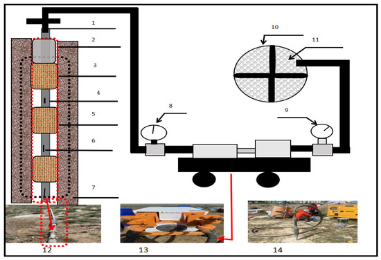
Figure 1.
Grouting method and equipment.
3.8. Test Instruments
Key characterization equipment employed in this study is summarized in Table 3.
Table 3.
List of testing instruments and their specifications.
4. Results
4.1. Rheological Property Analysis of the Grouting Material
4.1.1. Study on the Rheological Properties of Sodium-Based-Bentonite-Modified Cement-Based Grouting Materials
The rheological characteristics of the sodium-based-bentonite-modified cement-based grouting material are shown in Figure 2.
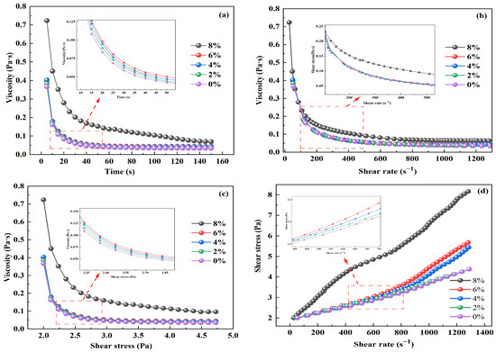
Figure 2.
Rheological characteristics of Na-bentonite-modified cement-based grouting material: (a) the relationship between time and viscosity; (b) the relationship between shear rate and viscosity; (c) the correlation between shear stress and viscosity; (d) the relationship between shear rate and shear stress.
As shown in Figure 2a, when the sodium-based bentonite content is 2%, the apparent viscosity decreases from 0.4 Pa·s to 0.05 Pa·s over 0–60 s, representing an 87.5% reduction. When Na-bentonite content increases to 8%, the decrease in apparent viscosity reaches 80.1%. At 60 s, the fluctuation range of the apparent viscosity for the slurry with different Na-bentonite contents is less than 5%, indicating that the rheological properties have entered a stable state by this point. The stable viscosity of the 8% content group was 0.1 Pa·s, which is significantly higher than the 0.05 Pa·s of the 2% group. The rapid decline phase from 0 to 60 s is attributed to the rapid hydration and expansion of Na-bentonite upon contact with water, which initially forms a loose structure. Over time, the slurry gradually disaggregates under shear stress, leading to a reduction in the internal resistance and a rapid drop in the apparent viscosity. The stable phase after 60 s arises because the destruction rate of the flocculent structure [22,23] reaches a dynamic equilibrium with the readsorption of bentonite particles, thereby stabilizing the internal structure of the slurry. This steady-state structure forms the basis for the slurry and has an impact on its non-Newtonian characteristics. Based on the observed characteristics—the viscosity decreasing from 0 to 60 s and stabilizing thereafter—it can be concluded that the slurry is likely a thixotropic non-Newtonian fluid. As shown in Figure 2b, varying the shear rate reveals that viscosity diminishes with rising shear rate, further confirming that the slurry is a non-Newtonian fluid. Comparing Figure 2a,b, the apparent viscosity decreases rapidly from 0 to 60 s, indicating that the fluidity of the slurry improves continuously within one minute after mixing. This stage corresponds to the optimal time window for grout diffusion. Viscosity tended to stabilize at 60 s, suggesting that the slurry can maintain stable flow properties over a relatively long period, facilitating control over the grouting time range. According to the viscosity design principles for grouting materials, we know that a material with a viscosity below 0.3 Pa·s will be prone to segregation, while one with a viscosity above 0.6 Pa·s will exhibit poor permeability [23,24]. Specifically, Refs. [23,24] report that the viscosity threshold for grouting slurries is 0.35–0.50 Pa·s. Therefore, viscosity should be reasonably controlled in applications involving water erosion.
As shown in Figure 2c, when the shear stress increases from 2.0 Pa to 3 Pa, the viscosity of the 2% sodium-based bentonite slurry decreases from 0.4 Pa·s to 0.05 Pa·s, while that of the 8% slurry decreases from 0.74 Pa·s to 0.11 Pa·s. Both exhibit a significant shear-thinning trend, with the viscosity of high-content Na-bentonite slurries remaining higher than that of low-content ones. Within a shear stress range of 2.0 Pa to 4.5 Pa, the viscosity reductions for slurries with different sodium-based bentonite contents are 87.9%, 87.5%, 86.8%, 86.3%, and 85.1%, respectively. This phenomenon can be explained as follows: at low shear stress, the force is insufficient to disrupt the network structure of the slurry. As shear stress increases, the network structure gradually breaks down, leading to a significant reduction in flow resistance and thus a decrease in viscosity. When the shear stress is sufficiently high, the network structure reaches its maximum destructibility, and the viscosity tends to stabilize. For slurries with different concentrations, the steady-state viscosity is still influenced by concentration: within the 2%~6% concentration range, the steady-state viscosity does not vary significantly. The shear-thinning property is beneficial in practical applications: it reduces viscosity during slurry pumping, thereby lowering pumping resistance and preventing pipe blockages. Once the slurry enters cracks, its viscosity increases, facilitating crack filling and enhancing adhesion with the surrounding soil. This forms an “interface protective coating” that effectively inhibits water migration and stabilizes the roadbed to resist freeze–thaw cycles. In optimizing sodium-based bentonite materials, one must consider the complex and variable environments of frozen ground roadbeds; here, the 4% content group is recommended due to its significant shear-thinning behavior and low pumping resistance.
As depicted in Figure 2d, the shear stress of sodium-based bentonite slurries with different contents increases monotonically with increasing shear rate, though the growth trend is nonlinear. At the same shear rate, the shear stress of the 8% sodium-based bentonite group is significantly higher than that of the 2% group, indicating that a higher content of sodium-based bentonite corresponds to greater shear stress at an equivalent shear rate. This is because the more compact structure formed by high-content sodium-based bentonite in the slurry [25] enhances internal resistance, thereby resulting in higher shear stress at the same shear rate. These results offer data support for the subsequent regulation of sodium-based bentonite content to match the stress requirements of different shear rate scenarios in engineering projects. They also lay an experimental foundation for a deeper understanding of the rheological properties of grouting materials.
4.1.2. Mechanism Analysis of the Effect of the Interaction Between Sodium-Based Bentonite and Cement Hydration Products on Their Rheological Properties
The regulation of the rheological properties of the slurry by sodium-based bentonite essentially arises from its interfacial interaction with cement hydration products. Based on cement hydration theory and previous research [26,27,28], its mechanism of action can be preliminarily inferred as follows:
1. Ion exchange reaction: In the initial stage of cement hydration, a large amount of Ca2+ is released (primarily from the hydration of C3S and C2S: 2C3S + 6H2O → C3S2H3 + 3Ca (OH)2). These Ca2+ ions may undergo exchange with the interlayer Na+ ions of sodium-based bentonite [29], with the proposed reaction equation being as follows: Bentonite-Na+ + Ca2+ → Bentonite-Ca2+ + 2 Na+.
This process may reduce the interlayer distance of bentonite (similar to the interlayer contraction phenomenon of bentonite in a high-Ca2+ environment reported in the literature [30]), while providing Ca2+ adsorption sites for the nucleation of calcium silicate hydrate (C-S-H), thereby promoting its formation.
2. Synergistic gel network formation: The layered silicate structure of bentonite is rich in Si-O groups, which may form hydrogen bonds with the Ca-OH groups in C-S-H, resulting in a “bentonite layer-C-S-H” cross-linked network. This aligns with the conclusion from similar studies that “clay can enhance the continuity of the C-S-H network through interfacial interactions” [31], suggesting that it may improve the structural stability of the system and thereby influence its macroscopic properties.
4.2. Mechanical Strength of the Grouting Material
The influence of cement-based grouting materials modified with different amounts of sodium bentonite on their compressive strength is presented in Figure 3.
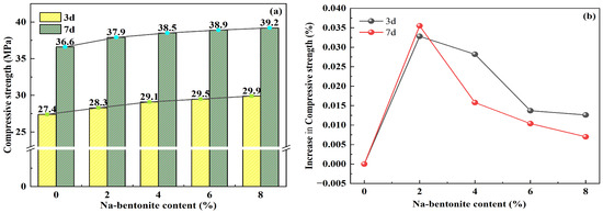
Figure 3.
Compressive strength of Na-bentonite-modified cement-modified cement-based grouting material: (a) variation in compressive strength with Na-bentonite content; (b) compressive strength variation versus Na-bentonite content.
Figure 3a shows that the strength development of cementitious grouting materials at various curing ages is significantly influenced by the content of sodium-based bentonite, with the impact becoming more pronounced as the bentonite dosage increases. This phenomenon can be attributed to the hygroscopic nature of sodium-based bentonite during cement slurry mixing. By absorbing water, it refines the pore structure of the slurry, effectively reducing porosity. Additionally, the fine particles of sodium-based bentonite act as fillers, occupying the voids within the cement matrix and enhancing its overall density, thereby contributing to strength improvement. As shown in Figure 3b, the increase in compressive strength in cementitious grouting materials first increases and then decreases with the increase in Na-bentonite content. This trend can be explained as follows: When the Na-bentonite content is below the critical value, its synergistic effect with cement hydration dominates strength enhancement. The Na+ ions between the bentonite layers can undergo ion exchange with the Ca2+ ions released during cement hydration [29], providing additional nucleation sites for C-S-H gel formation. This promotes the uniform growth of cementitious phases, significantly improving matrix density, and thereby synergistically enhancing compressive strength. When the sodium-based bentonite content exceeds the critical value, the decrease in strength increase is due to the combined effects of double internal stress accumulation and interface degradation. On the one hand, Na-bentonite has a limited water absorption and expansion capacity, so that excessive addition leads to a volume expansion of 3–5 times [32], i.e., far exceeding the elastic deformation limit of the cement matrix. The rigid skeleton formed by cement hydration cannot accommodate this excessive expansion, leading to the induction of internal tensile stress and subsequent microcracks. This aligns with the conclusion that has been discussed in the literature: “high bentonite content significantly increases the microcrack density in cement-based materials” [33]. On the other hand, high bentonite content tends to form a “bentonite-rich interface layer” between cement particles and bentonite aggregates. Insufficient filling of hydration products (e.g., C-S-H) in this layer causes a significant increase in porosity [34]. Thus, an appropriate amount of sodium-based bentonite enhances strength by optimizing interfaces and promoting compaction, while excessive addition reduces strength due to expansion-induced stress and interface defects.
4.3. Fluidity
Fluidity is a critical property of grouting materials: the fluidity of the roadbed should not exceed 17 s [35,36], as illustrated in Figure 4.
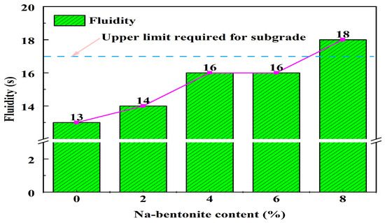
Figure 4.
Fluidity of Na-bentonite-modified cement-based grouting material.
Figure 4 shows that the fluidity of cement-based grouting materials exhibits a trend of initial increase, followed by stabilization, and then a subsequent rise as the content of sodium-based bentonite increases. This phenomenon is attributed to the water-absorbing and swelling properties of sodium-based bentonite. In the initial stage, it absorbs moisture from the surrounding cement slurry, thereby enhancing the fluidity of the mixture. As the content of sodium-based bentonite continues to increase, it adsorbs more water, which raises the slurry concentration and results in decreased fluidity. When the content of sodium-based bentonite is 4% or 6%, the fluidity of the slurry is equivalent. This is because the interlayer structure of sodium-based bentonite inhibits the hydration reaction of cement, delaying the loss of fluidity. Additionally, the swelling of sodium-based bentonite after water absorption may result in a denser slurry structure, contributing to the loss of fluidity. When the content of sodium-based bentonite reaches 8%, it exceeds the upper limit required for roadbed grouting. Therefore, the fluidity of grouting materials for highway subgrades should remain relatively stable to ensure proper solidification after grouting.
4.4. Setting Time
The effects of the different Na-bentonite contents on the initial and final setting times of cement-based grouting materials is illustrated in Figure 5.
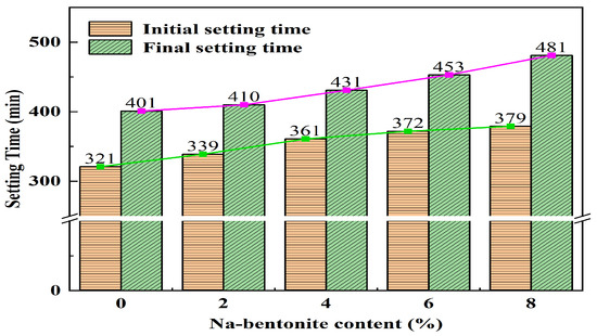
Figure 5.
Setting times of Na-bentonite-modified cement-based grouting material.
Figure 5 shows that the setting time of cement-based grouting materials prolongs as sodium-based bentonite is incorporated. This phenomenon can be attributed to the unique properties of sodium-based bentonite: upon contact with water, it swells and forms colloidal particles. These particles disperse within the cement-based slurry, physically obstructing the interaction between cement and water. Consequently, the cement hydration reaction is decelerated, leading to a delayed setting process. With increasing Na-bentonite dosage, an elevated number of colloidal particles are generated, intensifying the obstruction and extending the setting time.
The interaction mechanism between cement-based grouting materials and sodium-based bentonite involves ion adsorption and dispersion effects. Montmorillonite, a key component of sodium-based bentonite, carries a negative charge. It selectively adsorbs calcium ions produced during cement hydration, reducing the concentration of free ions in the grouting slurry. This ion adsorption significantly inhibits the formation of essential hydration products, thereby retarding the setting and hardening of the cement matrix. Moreover, the dispersive nature of sodium-based bentonite prevents the aggregation of cement particles, further contributing to the extended setting time.
In practical grouting applications, precise control over the bentonite dosage is crucial. Engineers must accurately measure and regulate the setting time of cementitious grouting materials, ensuring the smooth execution of grouting operations and achieving optimal engineering performance.
4.5. Rules of Grouting Time and Pressure of Modified Sodium Bentonite
The grouting pressure of sodium bentonite changes with time, as shown in Figure 6.
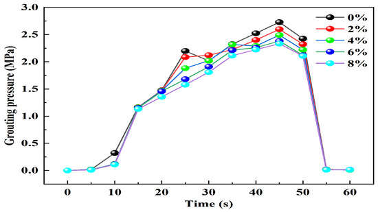
Figure 6.
The variation in the pressure of cement-based grouting materials modified with Na-bentonite over time.
Figure 6 shows that grouting pressure is not a constant; rather, it varies within a specific range that is correlated with the extent of crack formation in the cleaved grouting. Three stages can be distinguished in the evolution of grouting pressure over time: slow growth, fast growth, and quick reduction. During the slow-increase phase, the bonding force of the pipe–borehole gap stabilizes the grouting pressure fluctuation as the slurry enters the grouting tube. The grouting time is 10 s. The slurry starts to penetrate the soil and splits to create fractures when the grouting period of 10 to 45 s corresponds to the rapid growth phase. At this point, a high grouting pressure is needed, which increases the slurry diffusion distance and the fissure’s expansion rate. The fissure depth also gradually increases. The third stage is the rapid-reduction phase (45~60 s), during which the initial fissure develops and forms. The route for the slit is open. To release the pressure, keep dividing the weakness surrounding the borehole until it reaches the soil’s surface. Gradually, the necessary grouting pressure rises to its maximum and starts to stabilize. Consequently, the grouting pressure fluctuates within a certain range. According to the trend of modified sodium bentonite, the grouting pressure is constant in the beginning and decreases with the amount of sodium bentonite employed over time.
4.6. Rules of Grouting Time and Flow of Cement Base Modified by Sodium-Based Bentonite
The grouting time of the bentonite-modified cement base changes with the flow rate, as shown in Figure 7.
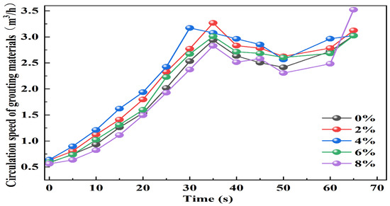
Figure 7.
Variation in circulation speed with grouting pressure at different times.
As shown in Figure 7, the grouting pump utilized in the experiment was TYPE YE2-160M-4, which has a constant output power of W = Pc Q. As a result, the grouting flow was mostly determined by the crack’s rate of expansion. This approach is extremely consistent with the variability observed in early-stage grouting pressure (time is 0~35 s). As the grouting pressure increases, the fissure expansion rate increases proportionately, increasing the quantity of grouting. However, as the grouting pressure grows over time, the corresponding flow rate also increases because the split channel must be opened to fill the crack; this requires more slurry, which raises the corresponding slurry. It is evident from the various sodium bentonite mixing curves shown in Figure 6 that the 4% bentonite with mixing has the fastest circulation speed due to the good fluidity of the sodium bentonite–cement reaction.
4.7. Diffusion Distance and Pulse Formation Regularity of Cement-Based Grouting Modified Sodium Bentonite
The diffusion distance and pulse of bentonite-modified cement base are shown in Figure 8.
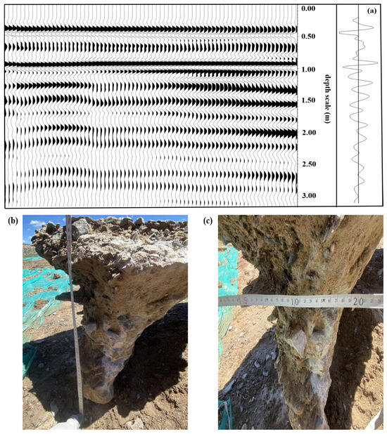
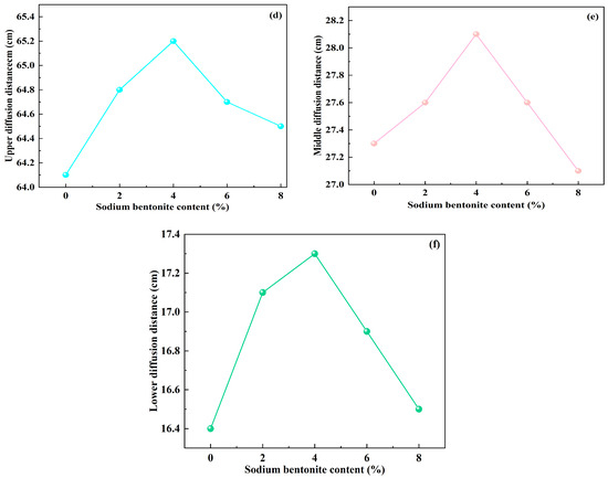
Figure 8.
Grouting slurry diffusion and distribution: (a) pulse distribution; (b) pulse vertical depth; (c) pulse diffusion distance; (d) relationship between sodium bentonite content and upper diffusion distance; (e) relationship between sodium bentonite content and middle diffusion distance; (f) relationship between sodium bentonite content and lower diffusion distance.
The distribution of the scanning area and the pulp sampled by the excavator is shown in Figure 8a–f. This is primarily shown as a pulse with a wide diffusion distance at the upper end of the slurry and a narrow diffusion distance at the lower end. The grouting slurry is wrapped in the soil particles and sand that are affixed to the soil. When the slurry accumulates to the weak force during the flow, this causes a huge higher end and a narrow bottom end. When combined with the field sampling of the diffusion distance, as illustrated in Figure 8d–f, the diffusion distance decreases as the amount of sodium bentonite increases. Because it prevents cement hydration, the high concentration of sodium bentonite in the soil in the swelling binding area reduces the diffusion distance when it surpasses 4%.
5. Conclusions
In this study, we evaluate the performance of sodium-based-bentonite-modified cement-based grouting materials through laboratory testing and field grouting experiments; accordingly, we systematically verified the applicability of this material as a functional barrier layer for the prevention of water accumulation in roadbeds in permafrost regions. Experiments were performed to identify the optimal range of sodium-based bentonite content, key performance parameters, and grouting process control conditions, providing a technical solution that combines theoretical support with engineering feasibility for the efficient management of water-accumulation-related road defects in permafrost regions. The main conclusions of this study are as follows:
- The Na-bentonite content exerts a significant regulatory effect on the rheological properties of cement-based grouting materials: as the content increases, the material’s consistency increases and its fluidity decreases, resulting in improved base consistency and enhanced shear thinning characteristics. This macro-scale phenomenon is closely related to the interfacial interaction between bentonite and cement hydration products. Theoretical analysis and existing research suggest that the mechanism may involve ion exchange between Ca2+ and Na+ in the bentonite layers, as well as the formation of a “bentonite–C–S–H” synergistic network. Here, the shear thinning property helps the slurry to completely fill the cracks in the soil, enhancing its bonding ability with the surrounding soil and thereby forming a continuous “interface protective coating” that effectively blocks water migration. This provides a critical safeguard for frozen soil subgrades to withstand freeze–thaw cycles and maintain stability.
- The content of Na-bentonite significantly affects the mechanical strength, flowability, and setting time of cement-based grouting materials; the mechanical strength increases with increasing content, but the increase is nonlinear. This is presumably due to a gradual decrease in the internal stress generated by the bentonite in the cement matrix. Fluidity shows an “upward–stable–upward” trend as its content increases. The setting time increases with increasing content, and this is particularly noticeable at high content levels. This is related to two mechanisms: higher proportions of bentonite adsorb moisture from the slurry to delay the cement hydration process, while the hydrated gel layer formed by its particles inhibits moisture migration into the cement particles, further extending the setting time.
- During the formation of a functional barrier layer by cement-based grouting materials, grouting pressure is strongly linked to the soil-crack-filling process. This process can be broadly divided into three stages: grout penetration, soil splitting, and filling of cracks after splitting. The grouting pressure decreases as the sodium-based bentonite content increases, which is related to the expansive properties of sodium-based bentonite, facilitating the full extension of the functional barrier layer in the cracks. When the sodium-based bentonite content is 4%, the flow rate is fastest, enabling the efficient formation of a continuous functional barrier layer. The above findings provide a reference for optimizing grouting process parameters and the control of the crack-filling effect of functional barrier layers.
- Based on the results of ground-penetrating radar scanning and on-site sampling, it can be concluded that the distribution of grout veins in the functional barrier layer formed by grouting is basically consistent. It primarily exhibits a conical feature with a wide diffusion distance at the upper end and a narrow diffusion distance at the lower end. The grouting slurry can tightly adhere to the sand, gravel, and soil particles in the soil, enhancing the integrity between the functional barrier layer and the surrounding soil. The diffusion distance of the functional barrier layer formed by cement-based grouting materials increases first and then decreases as the sodium-based bentonite content increases. When the sodium-based bentonite content is 4%, the diffusion distance reaches its maximum, which is more conducive to the formation of a functional barrier layer with an appropriate range and continuous structure.
Author Contributions
Conceptualization, S.H.; methodology, S.H.; software, S.H.; validation, S.H., H.W. and Z.L.; formal analysis, S.H.; investigation, S.H.; resources, B.T. and K.N.; data curation, S.H.; writing—original draft preparation, S.H.; writing—review and editing, S.H.; visualization, S.H.; supervision, S.H.; project administration, B.T. All authors have read and agreed to the published version of the manuscript.
Funding
This research received no external funding.
Institutional Review Board Statement
Not applicable.
Informed Consent Statement
Not applicable.
Data Availability Statement
Data is contained within the article.
Conflicts of Interest
The authors declare no conflicts of interest.
References
- Gao, X.; Lin, K.; Liu, M.; Dong, C.; Yao, Z.; Liu, Z.; Xiao, M.; Xie, X.; Huang, L. Dynamic Changes in Permafrost Distribution over China and Their Potential Influencing Factors under Climate Warming. Sci. Total Environ. 2023, 874, 162624. [Google Scholar] [CrossRef]
- Ma, J.J.; Li, R.; Liu, H.C.; Huang, Z.W.; Wu, T.H.; Hu, G.J.; Xiao, Y.; Zhao, L.; Du, Y.Z.; Yang, S.H. The Surface Energy Budget and Its Impact on the Freeze-Thaw Processes of Active Layer in Permafrost Regions of the Qinghai-Tibetan Plateau. Adv. Atmos. Sci. 2022, 39, 189–200. [Google Scholar] [CrossRef]
- Vasil’CHuk, Y.K.; Vasil’CHuk, A.C.; Budantseva, N.A.; Vasil’CHuk, J.Y.; Ginzburg, A.P. Synchronous Isotopic Curves in Ice Wedges of the Batagay Yedoma: Precision Matching and Similarity Scoring. Permafr. Periglac. Process. 2024, 35, 478–492. [Google Scholar] [CrossRef]
- Nurlybayev, R.E.; Kuldeyev, E.I.; Yestemessova, A.S.; Altayeva, Z.N.; Orynbekov, Y.S.; Murzagulova, A.A.; Iskakov, A.A.; Abisheva, G.K.; Khamza, Y.Y. ThermalInsulation Dry Construction Mixture Based on Diatomite. Coatings 2025, 15, 811. [Google Scholar] [CrossRef]
- Li, D.; Wu, M.; Xia, R.; Hu, J.; Huang, F. Construction of Silane-Modified Diatomite-Magnetic Nanocomposite Superhydrophobic Coatings Using Multi-Scale Composite Principle. Coatings 2025, 15, 786. [Google Scholar] [CrossRef]
- Wen, P.; Feng, Z.; Zheng, B. Influence of cationic polymer on the floccule size of cement pastes containing polycarboxylate superplasticizer and Na-bentonite. Korea-Aust. Rheol. J. 2023, 35, 105–116. [Google Scholar] [CrossRef]
- Liu, M.; Hu, Y.; Lai, Z.; Yan, T.; Lv, S. Influence of various bentonites on the mechanical properties and impermeability of cement mortars. Constr. Build. Mater. 2020, 241, 118015. [Google Scholar] [CrossRef]
- Lee, K.F. Experimental Study on the Influence of Bentonite Dosage on Cement Grouting Strength. J. Luoyang Inst. Sci. Technol. (Nat. Sci. Ed.) 2017, 27, 5. [Google Scholar] [CrossRef]
- Yang, J.; Cheng, Y.; Chen, W.; Shi, Y. Experimental Study on Diffusion Law of Post-Grouting Slurry in Sandy Soil. Adv. Civ. Eng. 2019, 2019, 93942. [Google Scholar] [CrossRef]
- Sha, F.; Lin, C.; Li, Z.; Liu, R. Reinforcement simulation of water-rich and broken rock with Portland cement-based grout. Constr. Build. Mater. 2019, 221, 292–300. [Google Scholar] [CrossRef]
- Liu, Q.; Lei, G.; Peng, X.; Lu, C.; Wei, L. Rheological Characteristics of Cement Grout and its Effect on Mechanical Properties of a Rock Fracture. Rock Mech. Rock Eng. 2017, 51, 613–625. [Google Scholar] [CrossRef]
- Xie, B.; Wang, X.; Cheng, H.; Li, M.; Rong, C. Dewaterability, rheology, and penetration diffusion characteristics of modified power-law cement slurry. Constr. Build. Mater. 2024, 436, 136814. [Google Scholar] [CrossRef]
- Huang, X.S.; Zhang, C.; Cheng, C.; Zhao, Y.J. Study on the expansion law of split induced by grouting with similar samples. Coal Mine Saf. 2021, 52, 43–48. [Google Scholar] [CrossRef]
- Li, H.; Zhang, Y.; Wu, J.; Zhang, X.; Zhang, L.; Li, Z. Grouting sealing mechanism of water gushing in karst pipelines and engineering application. Constr. Build. Mater. 2020, 254, 119250. [Google Scholar] [CrossRef]
- Zhang, J.; Zhao, C.; Wu, Y. Experimental Study on Post-Grouting Pile Vertical Bearing Performance Considering Different Grouting Methods and Parameters in Cohesive Soil. Appl. Sci. 2023, 13, 12175. [Google Scholar] [CrossRef]
- Güllü, H.; Cevik, A.; Al-Ezzi, K.M.; Gülsan, M.E. On the rheology of using geopolymer for grouting: A comparative study with cement-based grout included fly ash and cold bonded fly ash. Constr. Build. Mater. 2019, 196, 594–610. [Google Scholar] [CrossRef]
- Lin, H.; Yin, Z.; Li, S. Optimization of Cementitious Material with Thermal-Activated Lead–Zinc Tailings Based on Response Surface Methodology. Materials 2024, 17, 2926. [Google Scholar] [CrossRef]
- Wang, Q.-B.; Zhu, Q.-K.; Shao, T.-S.; Yu, X.-G.; Xu, S.-Y.; Zhang, J.-J.; Kong, Q.-L. The rheological test and application research of glass fiber cement slurry based on plugging mechanism of dynamic water grouting. Constr. Build. Mater. 2018, 189, 119–130. [Google Scholar] [CrossRef]
- Feng, X.; Wang, Y.; Li, L.; Jiang, Z.; Zhou, G.; Wu, Q.; Wang, T. Experimental investigation on physical properties and early-stage strength of ultrafine fly ash-based geopolymer grouting material. Constr. Build. Mater. 2024, 441, 137526. [Google Scholar] [CrossRef]
- JTG 3420-2020; Testing Methods of Cement and Concrete for Highway Engineering. Ministry of Transport of the People’s Republic of China: Beijing, China, 2020.
- JC/T 474-2008; Mortar and Concrete Waterproofing Agent. The National Development and Reform Commission of the People’s Republic of China: Beijing, China, 2008.
- Abu-Jdayil, B.; Ghannam, M.; Ahmed, K.A.; Djama, M. The Effect of Biopolymer Chitosan on the Rheology and Stability of Na-Bentonite Drilling Mud. Polymers 2021, 13, 3361. [Google Scholar] [CrossRef]
- Liu, C.; Hong, B.; Xu, K.; Zhang, M.; An, H.; Tan, Y.; Wang, P. Synthesis and application of salt tolerance amphoteric hydrophobic associative flocculants. Polym. Bull. 2014, 71, 3051–3065. [Google Scholar] [CrossRef]
- Li, X.; Zheng, X.; Xu, Y. Study on surface erosion threshold and erosion mass of bentonite applied in nuclear waste repository based on fractal structure characteristics. Nucl. Eng. Des. 2024, 422, 113177. [Google Scholar] [CrossRef]
- Sun, Y.; Zhou, Y.; Wei, X.; Dong, J.; Chen, N.; Ren, Q.; Wang, J.; Ke, W. Effects of iron corrosion products on the degradation of bentonite structure and properties. npj Mater. Degrad. 2023, 7, 66. [Google Scholar] [CrossRef]
- Qi, T.; Zhou, W.; Liu, X.; Wang, Q.; Zhang, S. Predictive Hydration Model of Portland Cement and Its Main Minerals Based on Dissolution Theory and Water Diffusion Theory. Materials 2021, 14, 595. [Google Scholar] [CrossRef]
- Dong, E.; Li, G.; Chen, Z.; Feng, Y.; Wang, Z.; Fan, D.; Liu, K.; Yin, T.; Yu, R. Investigating hydration characteristics of Portland cement-calcium sulfoaluminate cement-gypsum ternary cementitious system with low water binder ratio:a magnetism-heat theory approach. J. Build. Eng. 2023, 80, 107976. [Google Scholar] [CrossRef]
- Ray, S.; Dash, J.; Devi, N.; Sasmal, S.; Pesala, B. Comparative Study of Hydration Kinetics of Cement and Tricalcium Silicate Using Terahertz Spectroscopy and Density Functional Theory Simulations. J. Infrared Millim. Terahertz Waves 2018, 39, 651–666. [Google Scholar] [CrossRef]
- Yu, Z.; Xie, Z.; Zhang, T.; Yue, G.; Liu, H.; Li, Q.; Wang, L. Influence of Potassium-Based Alkaline Electrolyzed Water on Hydration Process and the Properties of Cement-Based Materials with Fly Ash. Materials 2021, 14, 6956. [Google Scholar] [CrossRef]
- Brown, K.; Mendoza, M.; Tinsley, T.; Bee-DiGregorio, M.Y.; Bible, M.; Brooks, J.L.; Colorado, M.; Esenther, J.; Farag, A.; Gill, R.; et al. Polyvinyl alcohol-montmorillonite composites for water purification: Analysis of clay mineral cation exchange and composite particle synthesis. Polyhedron 2021, 205, 115297. [Google Scholar] [CrossRef]
- Du, S.; Peng, T.; Song, S.; Gu, G.; Wang, Y. Effect of calcium ions on bentonite network structure. Miner. Eng. 2022, 186, 107724. [Google Scholar] [CrossRef]
- Li, Y.; Xu, J.; Wang, Z.; Wang, B. Experimental Study on Microstructure and Hydraulic Performance of Bentonite Modified Loess. KSCE J. Civ. Eng. 2023, 27, 2778–2791. [Google Scholar] [CrossRef]
- Vijay, C.; Reddy, M.A.K. Optimization of bentonite modified cement mortar parameters at elevated temperatures using RSM. IOP Conf. Ser. Mater. Sci. Eng. 2021, 1197, 012040. [Google Scholar] [CrossRef]
- Li, J.; Zha, W.; Lv, W.; Xu, T.; Wang, B.; Wang, B. Mechanical properties and sulfate resistance of basalt fiber-reinforced alkali-activated fly ash-slag-based coal gangue pervious concrete. Case Stud. Constr. Mater. 2024, 21, e03961. [Google Scholar] [CrossRef]
- SZ-G-B04-2007; Technical Specification for Reinforcement of Highway Subgrade and Base Polymer Grouting. Shanghai Municipal Engineering Administration: Shanghai, China, 2007.
- Tian, Z.; Zhang, Z.; Zhang, K.; Tang, X.; Huang, S. Statistical modeling and multi-objective optimization of road geopolymer grouting material via RSM and MOPSO. Constr. Build. Mater. 2021, 271, 121534. [Google Scholar] [CrossRef]
Disclaimer/Publisher’s Note: The statements, opinions and data contained in all publications are solely those of the individual author(s) and contributor(s) and not of MDPI and/or the editor(s). MDPI and/or the editor(s) disclaim responsibility for any injury to people or property resulting from any ideas, methods, instructions or products referred to in the content. |
© 2025 by the authors. Licensee MDPI, Basel, Switzerland. This article is an open access article distributed under the terms and conditions of the Creative Commons Attribution (CC BY) license (https://creativecommons.org/licenses/by/4.0/).