

Surface Treatments on Cobalt–Chromium Alloys for Layering Ceramic Paint Coatings in Dental Prosthetics

 ,
,  , ,
, ,  ,
, 
Abstract
1. Introduction
2. Materials and Methods
2.1. Materials
2.2. Methods
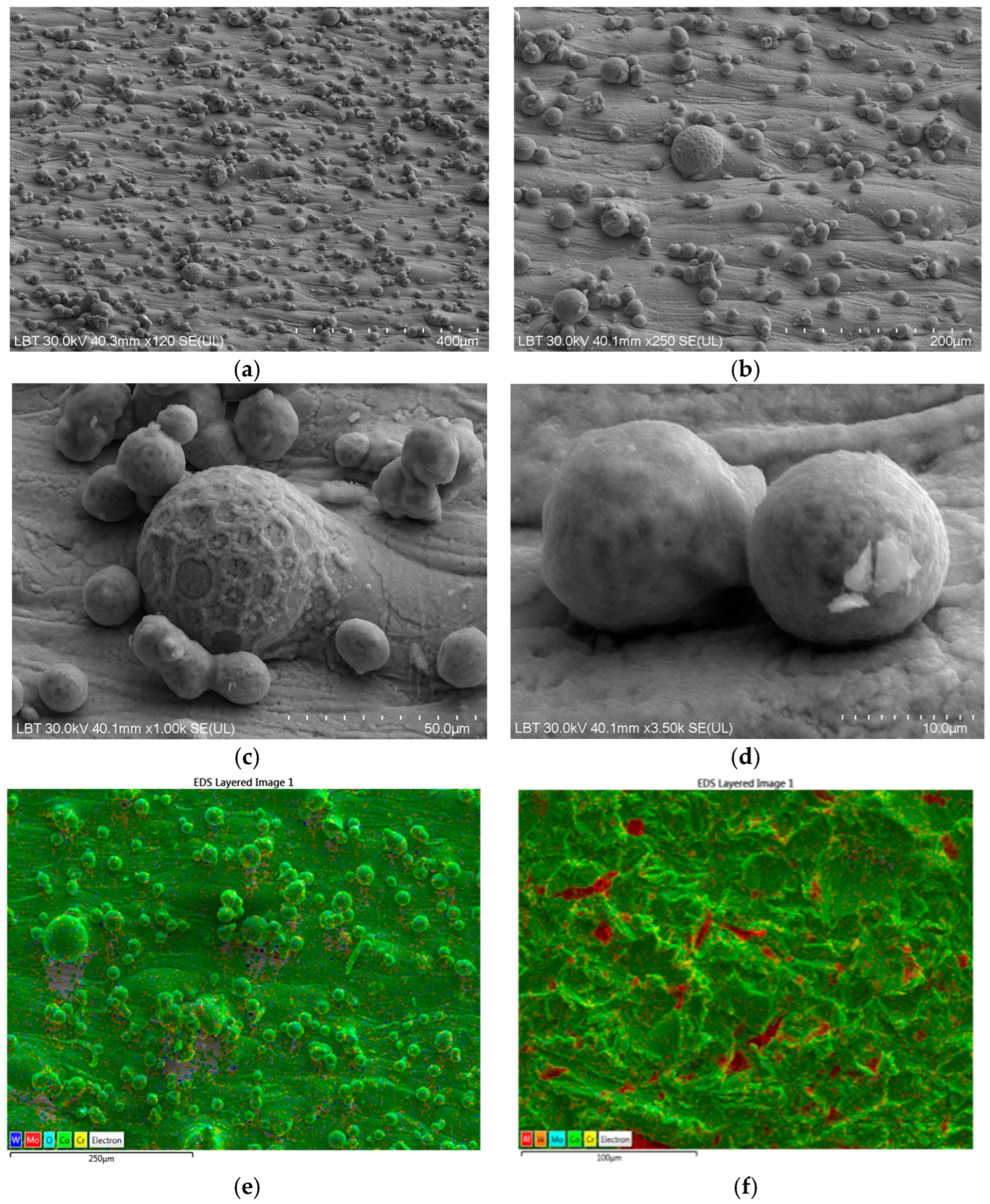
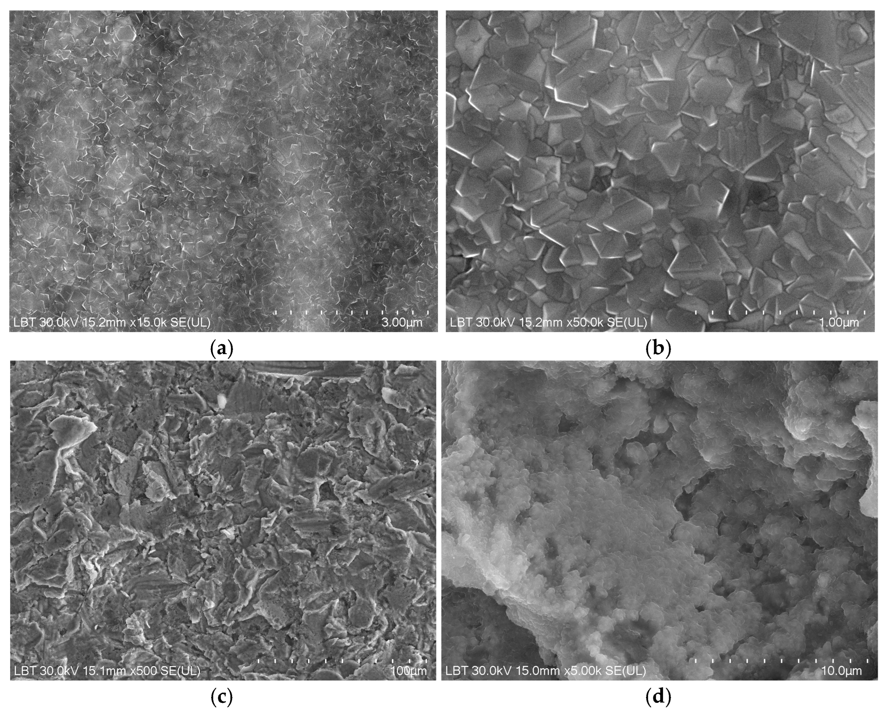
2.2.1. Scanning Electron Microscopy and Energy Dispersive Spectroscopy Analysis
2.2.2. Optical 3D Scanning for Surface Roughness Characterization
2.2.3. Drop Shape Analysis and Surface Contact Angle
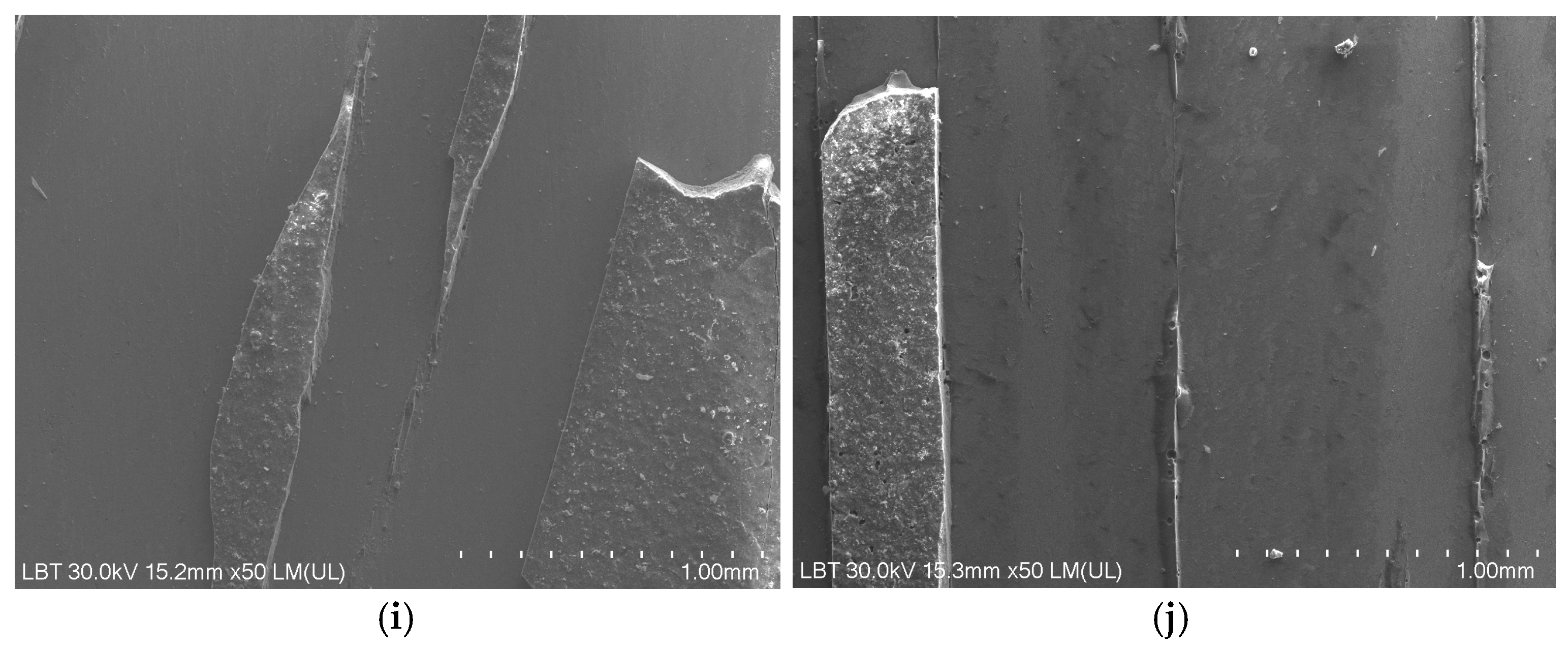
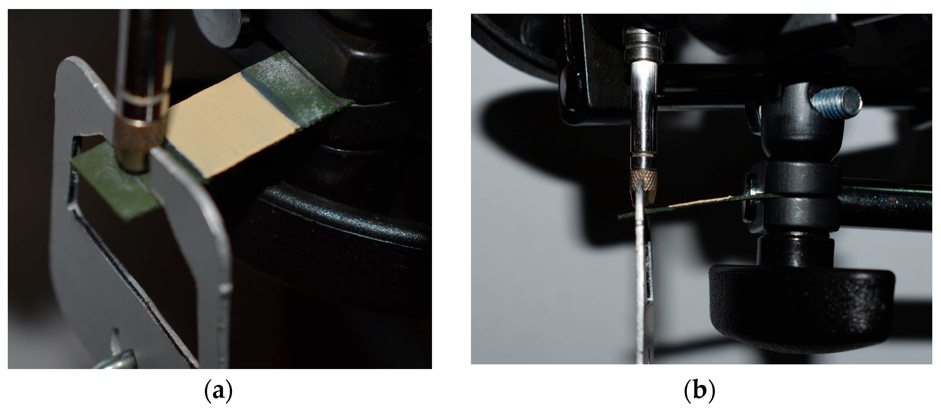
2.2.4. Mechanical Tests
3. Results
3.1. Scanning Electron Microscopy and Energy-Dispersive Spectroscopy Results
3.2. Roughness Surfaces Profile
3.3. Drop Shape Analysis Results
3.4. Mechanical Test Results
4. Discussion
5. Conclusions
Author Contributions
Funding
Institutional Review Board Statement
Informed Consent Statement
Data Availability Statement
Conflicts of Interest
References
- Al Jabbari, Y.S. Physico-mechanical properties and prosthodontic applications of Co-Cr dental alloys: A review of the literature. J. Adv. Prosthodont. 2014, 6, 138–145. [Google Scholar] [CrossRef]
- O’Brien, W.J. Dental Materials and Their Selection, 3rd ed.; Quintessence Publishing Co., Inc.: Chicago, IL, USA, 2002. [Google Scholar]
- Antoniac, I.V. (Ed.) Handbook of Bioceramics and Biocomposites; Springer Nature: Cham, Switzerland, 2016. [Google Scholar] [CrossRef]
- General Classes of Biomaterials. In Craig’s Restorative Dental Materials; Elsevier: Amsterdam, The Netherlands, 2012; pp. 135–146. [CrossRef]
- Paniz, G.; Kim, Y.; Abualsaud, H.; Hirayama, H. Influence of framework design on the cervical color of metal ceramic crowns. J. Prosthet. Dent. 2011, 106, 310–318. [Google Scholar] [CrossRef] [PubMed]
- Schwendicke, F. Digital Dentistry: Advances and Challenges. J. Clin. Med. 2020, 9, 4005. [Google Scholar] [CrossRef] [PubMed]
- Viderščak, D.; Schauperl, Z.; Šolić, S.; Ćatić, A.; Godec, M.; Kocijan, A.; Paulin, I.; Donik, Č. Additively Manufactured Commercial Co-Cr Dental Alloys: Comparison of Microstructure and Mechanical Properties. Materials 2021, 14, 7350. [Google Scholar] [CrossRef] [PubMed] [PubMed Central]
- Savencu, C.E.; Șerban, C.; Porojan, L. Adaptability Evaluation of Metal-Ceramic Crowns Obtained by Additive and Subtractive Technologies. Appl. Sci. 2020, 10, 5563. [Google Scholar] [CrossRef]
- Revilla-León, M.; Özcan, M. Additive Manufacturing Technologies Used for 3D Metal Printing in Dentistry. Curr. Oral Health Rep. 2017, 4, 201–208. [Google Scholar] [CrossRef]
- Yu, J.-M.; Kang, S.-Y.; Lee, J.-S.; Jeong, H.-S.; Lee, S.-Y. Mechanical Properties of Dental Alloys According to Manufacturing Process. Materials 2021, 14, 3367. [Google Scholar] [CrossRef]
- Liu, Y.; Shen, J.Z. Clinical Failures of Ceramic Dental Prostheses. In Advanced Ceramics for Dentistry; Elsevier: Amsterdam, The Netherlands, 2014; pp. 77–102. [Google Scholar] [CrossRef]
- Messer, R.; Wataha, J. Dental Materials: Biocompatibility. In Encyclopedia of Materials: Science and Technology; Elsevier: Amsterdam, The Netherlands, 2002; pp. 1–10. [Google Scholar] [CrossRef]
- Dawod, N.; Miculescu, M.; Antoniac, I.V.; Miculescu, F.; Agop-Forna, D. Metal–Ceramic Compatibility in Dental Restorations According to the Metallic Component Manufacturing Procedure. Materials 2023, 16, 5556. [Google Scholar] [CrossRef]
- Chirca, O.; Biclesanu, C.; Florescu, A.; Stoia, D.I.; Pangica, A.M.; Burcea, A.; Vasilescu, M.; Antoniac, I.V. Adhesive-Ceramic Interface Behavior in Dental Restorations. FEM Study and SEM Investigation. Materials 2021, 14, 5048. [Google Scholar] [CrossRef] [PubMed] [PubMed Central]
- Cobalt-Chrome Medyloy–Sco, Technical Dates-Instruction for Use. Available online: https://www.bego.com/fileadmin/user_downloads/Mediathek/Medical/Leistungskatalog/EN/me_800160_0015_br_en.pdf (accessed on 8 July 2025).
- Della Bona, A.; Borba, M.; Benetti, P.; Pecho, O.E.; Alessandretti, R.; Mosele, J.C.; Mores, R.T. Adhesion to Dental Ceramics. Curr. Oral. Health Rep. 2014, 1, 232–238. [Google Scholar] [CrossRef]
- Ko, K.-H.; Kang, H.-G.; Huh, Y.-H.; Park, C.-J.; Cho, L.-R. Effects of heat treatment on the microstructure, residual stress, and mechanical properties of Co-Cr alloy fabricated by selective laser melting. J. Mech. Behav. Biomed. Mater. 2022, 126, 105051. [Google Scholar] [CrossRef] [PubMed]
- Lemos, C.A.A.; Verri, F.R.; Gomes, J.M.d.L.; Batista, V.E.d.S.; Cruz, R.S.; e Oliveira, H.F.F.; Pellizzer, E.P. Ceramic versus metal-ceramic implant-supported prostheses: A systematic review and meta-analysis. J. Prosthet. Dent. 2019, 121, 879–886.e4. [Google Scholar] [CrossRef] [PubMed]
- Worpenberg, C.; Stiesch, M.; Eisenburger, M.; Breidenstein, B.; Busemann, S.; Greuling, A. The effect of surface treatments on the adhesive bond in all-ceramic dental crowns using four-point bending and dynamic loading tests. J. Mech. Behav. Biomed. Mater. 2023, 139, 105686. [Google Scholar] [CrossRef] [PubMed]
- Kassapidou, M.; Hjalmarsson, L.; Johansson, C.B.; Hammarström Johansson, P.; Morisbak, E.; Wennerberg, A.; Franke Stenport, V. Cobalt-chromium alloys fabricated with four different techniques: Ion release, toxicity of released elements and surface roughness. Dent. Mater. 2020, 36, e352–e363. [Google Scholar] [CrossRef] [PubMed]
- Belkhode, V.M.; Nimonkar, S.V.; Godbole, S.R.; Nimonkar, P.; Sathe, S.; Borle, A. Evaluation of the effect of different surface treatments on the bond strength of non-precious alloy–ceramic interface: An SEM study. J. Dent. Res. Dent. Clin. Dent. Prospect. 2019, 13, 200–207. [Google Scholar] [CrossRef] [PubMed] [PubMed Central]
- Yoo, S.Y.; Kim, S.K.; Heo, S.J.; Koak, J.Y.; Kim, J.G. Effects of Bonding Agents on Metal-Ceramic Bond Strength of Co-Cr Alloys Fabricated by Selective Laser Melting. Materials 2020, 13, 4322. [Google Scholar] [CrossRef] [PubMed] [PubMed Central]
- Xiang, N.; Xin, X.Z.; Chen, J.; Wei, B. Metal-ceramic bond strength of Co-Cr alloy fabricated by selective laser melting. J. Dent. 2012, 40, 453–457. [Google Scholar] [CrossRef] [PubMed]
- Li, J.; Ye, X.; Li, B.; Liao, J.; Zhuang, P.; Ye, J. Effect of oxidation heat treatment on the bond strength between a ceramic and cast and milled cobalt-chromium alloys. Eur. J. Oral Sci. 2015, 123, 297–304. [Google Scholar] [CrossRef] [PubMed]
- Uriciuc, W.A.; Boșca, A.B.; Băbțan, A.M.; Vermeșan, H.; Cristea, C.; Tertiș, M.; Pășcuță, P.; Borodi, G.; Suciu, M.; Barbu-Tudoran, L.; et al. Study on the Surface of Cobalt-Chromium Dental Alloys and Their Behavior in Oral Cavity as Cast Materials. Materials 2022, 15, 3052. [Google Scholar] [CrossRef] [PubMed] [PubMed Central]
- Bajraktarova-Valjakova, E.; Korunoska-Stevkovska, V.; Kapusevska, B.; Gigovski, N.; Bajraktarova-Misevska, C.; Grozdanov, A. Contemporary Dental Ceramic Materials, A Review: Chemical Composition, Physical and Mechanical Properties, Indications for Use. Open Access Maced. J. Med. Sci. 2018, 6, 1742–1755. [Google Scholar] [CrossRef] [PubMed] [PubMed Central]
- Zhang, S.; Li, Y.; Hao, L.; Xu, T.; Wei, Q.; Shi, Y. Metal-ceramic bond mechanism of the Co-Cr alloy denture with original rough surface produced by selective laser melting. Chin. J. Mech. Eng. 2014, 27, 69–78. [Google Scholar] [CrossRef]
- Huhtamäki, T.; Tian, X.; Korhonen, J.T.; Ras, R.H.A. Surface-wetting characterization using contact-angle measurements. Nat. Protoc. 2018, 13, 1521–1538. [Google Scholar] [CrossRef] [PubMed]
- Available online: https://www.3shape.com/en/news/2012/3shape-releases-3shape-cambridge-2012 (accessed on 8 July 2025).
- Available online: https://www.kruss-scientific.com/en/products-services/products/dsa100e (accessed on 8 July 2025).
- Gere, J.M.; Goodno, B.J. Mechanics of Materials, 8th ed.; SI; Cengage Learning: Boston, MA, USA, 2013. [Google Scholar]
- Hibbeler, R.C. Mechanics of Materials, 6th ed.; Pearson Education International: London, UK, 2005. [Google Scholar]
- Botean, A.I. Rezistenţa Materialelor. Solicitări Simple, Ediţia a II–A Revizuită şi Adăugită; Editura UT Press: Cluj-Napoca, Romania, 2019. [Google Scholar]
- Botean, A.I. The use of trigonometric series for the study of isotropic beam deflection. Mathematics 2023, 11, 1426. [Google Scholar] [CrossRef]
- Yan, X.; Xu, Y.X.; Wu, Y.; Lin, H. Effects of heat treatment on metal-ceramic combination of selective-laser-melted cobalt-chromium alloy. J. Prosthet. Dent. 2018, 120, 319.e1–319.e6. [Google Scholar] [CrossRef]
- Hong, J.K.; Kim, S.K.; Heo, S.J.; Koak, J.Y. Mechanical Properties and Metal-Ceramic Bond Strength of Co-Cr Alloy Manufactured by Selective Laser Melting. Materials 2020, 13, 5745. [Google Scholar] [CrossRef] [PubMed] [PubMed Central]
- Lee, S.H.; Takahashi, E.; Nomura, N.; Chiba, A. Effect of heat treatment on microstructure and mechanical properties of Ni-and C-free Co-Cr-Mo alloys for medical applications. Mater. Trans. 2005, 46, 1790–1793. [Google Scholar] [CrossRef]
- Van Noort, R. The future of dental devices is digital. Dent. Mater. 2012, 28, 3–12. [Google Scholar] [CrossRef]
- Nishigawa, G.; Maruo, Y.; Irie, M.; Maeda, N.; Yoshihara, K.; Nagaoka, N.; Matsumoto, T.; Minagi, S. Various Effects of Sandblasting of Dental Restorative Materials. PLoS ONE 2016, 11, e0147077. [Google Scholar] [CrossRef] [PubMed] [PubMed Central]
- Takaichi, A.; Kajima, Y.; Kittikundecha, N.; Htat, H.L.; Cho, H.H.W.; Hanawa, T.; Yoneyama, T.; Wakabayashi, N. Effect of heat treatment on the anisotropic microstructural and mechanical properties of Co-Cr-Mo alloys produced by selective laser melting. J. Mech. Behav. Biomed. Mater. 2020, 102, 103496. [Google Scholar] [CrossRef]
- Bakulin, A.V.; Kulkova, S.E.; Hocker, S.; Schmauder, S. Investigation of chemical bonding at metal-ceramic interfaces. IOP Conf. Ser. Mater. Sci. Eng. 2012, 38, 012014. [Google Scholar] [CrossRef]
- Kubiak, K.J.; Wilson, M.C.T.; Mathia, T.G.; Carval, P. Wettability versus roughness of engineering surfaces. Wear 2011, 271, 523–528. [Google Scholar] [CrossRef]


| Chemical Elements | Co | Cr | W | Mo | Si |
|---|---|---|---|---|---|
| wt% | 63.9 | 24.7 | 5.4 | 5.0 | 1.0 |
| P | SB250-1 | MP | HTT | SB250-2 | CB | PO-1 | PO-2 | PO-3 |
|---|---|---|---|---|---|---|---|---|
| P1 | x | - | - | - | - | x | x | x |
| P2 | x | - | x | - | - | x | x | x |
| P3 | x | - | x | x | - | x | x | x |
| P4 | x | - | x | x | x | x | x | x |
| P5 | x | - | - | - | x | x | x | x |
| P6 | x | - | x | - | x | x | x | x |
| P7 | - | x | - | - | - | x | x | x |
| P8 | - | x | x | - | - | x | x | x |
| P9 | - | x | x | - | x | x | x | x |
| P10 | - | x | - | - | x | x | x | x |
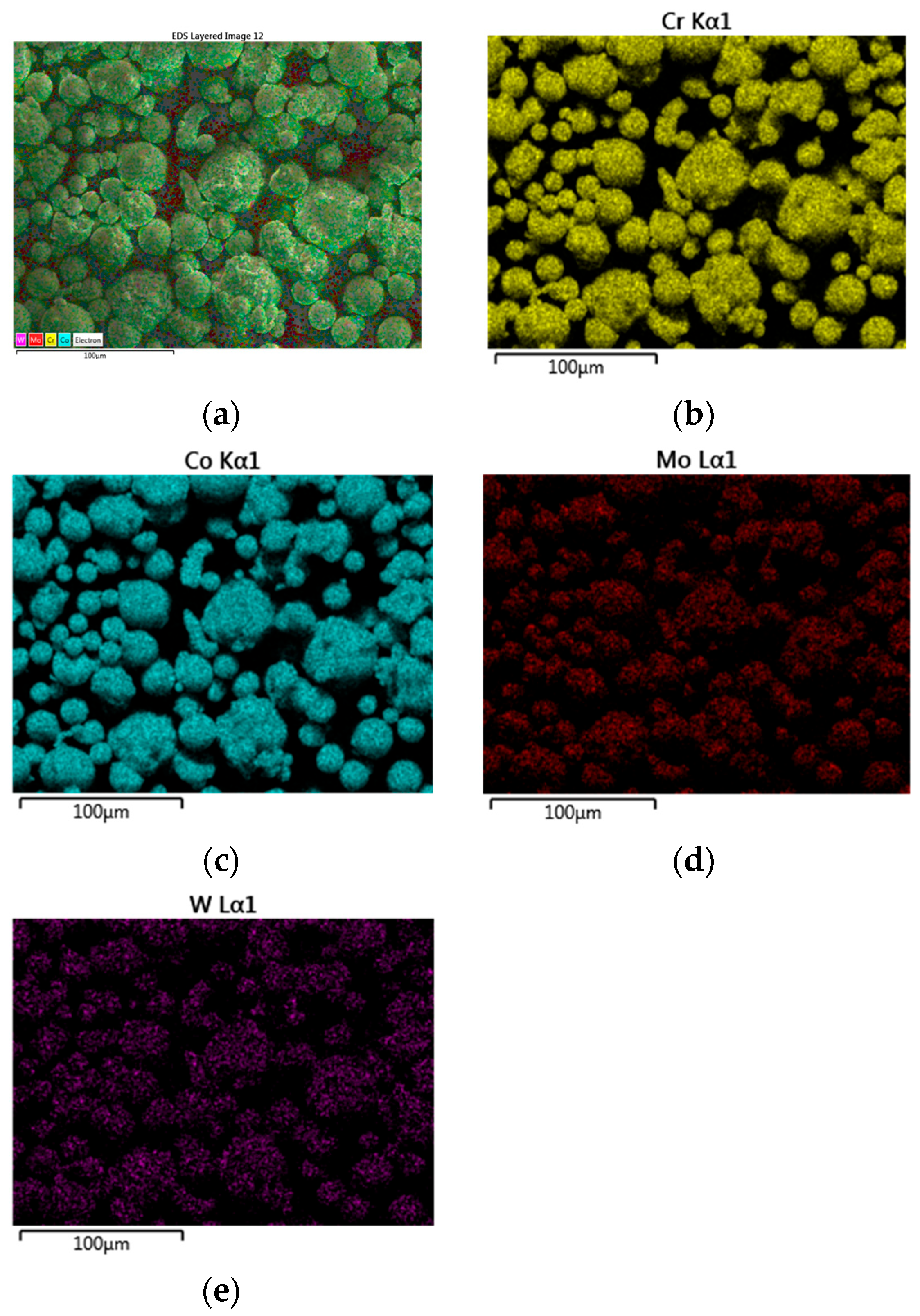
| Chemical Elements wt% | Co | Cr | Mo | W | O | Al |
|---|---|---|---|---|---|---|
| powder alloy (Mediloy S-Co, BEGO) based on instruction for use | 63.9 | 24.7 | 5.4 | 5.0 | - | - |
| powder alloy (Mediloy S-Co, BEGO) EDS results | 63.0 | 25.3 | 6.0 | 5.4 | - | - |
| SB sample | 5.3 | 21.5 | 3.9 | 4.2 | 8.0 | 9.1 |
| MP sample | 64.1 | 25.2 | 5.3 | 5.1 | - | - |
| SB + HTT sample | 40.7 | 22.8 | 2.6 | 3.1 | 24.3 | 6.5 |
| MP + HTT sample | 45.1 | 22.2 | 3.3 | 3.8 | 25.5 | - |
| SB + HTT + SB sample | 52.4 | 20.7 | 1.9 | 4.0 | 8.7 | 10.3 |
| Unit | SB | SB + HTT | MP | MP + HTT | |
|---|---|---|---|---|---|
| Number of data values | Elem. | 826,336 | 1,004,757 | 2,242,323 | 1,526,855 |
| Number of histograms | Class. | 115 | 112 | 146 | 64 |
| Mean data values | [μm] | 0.077 | 0.048 | 0.020 | 0.065 |
| σ | [μm] | 0.863 | 0.861 | 0.598 | 0.635 |
| Ra | [μm] | 0.58 | 0.58 | 0.14 | 0.35 |
| Rq | [μm] | 0.73 | 0.73 | 0.18 | 0.18 |
| Rz | [μm] | 4.12 | 4.25 | 0.91 | 0.91 |
| Sa | [μm] | 0.685 | 0.677 | 0.445 | 0.480 |
| Sq | [μm] | 0.867 | 0.863 | 0.598 | 0.638 |
| Sp | [μm] | 5.141 | 8.856 | 5.858 | 9.192 |
| Sv | [μm] | 5.515 | 5.298 | 3.000 | 5.806 |
| Sz | [μm] | 10.656 | 14.155 | 8.858 | 14.998 |
| S10z | [μm] | 9.272 | 11.693 | 6.773 | 12.432 |
| Ssk | 0.134 | 0.127 | −0.225 | −0.561 | |
| Sku | 3.337 | 3.797 | 4.653 | 6.425 | |
| Sdq | 0.119 | 0.112 | 0.031 | 0.058 | |
| Sdr | % | 0.674 | 0.608 | 0.046 | 0.164 |
| FLTt | [μm] | 10.656 | 14.155 | 8.858 | 14.998 |
| Lc | [μm] | 800.00 | 800.000 | 800.000 | 800.000 |
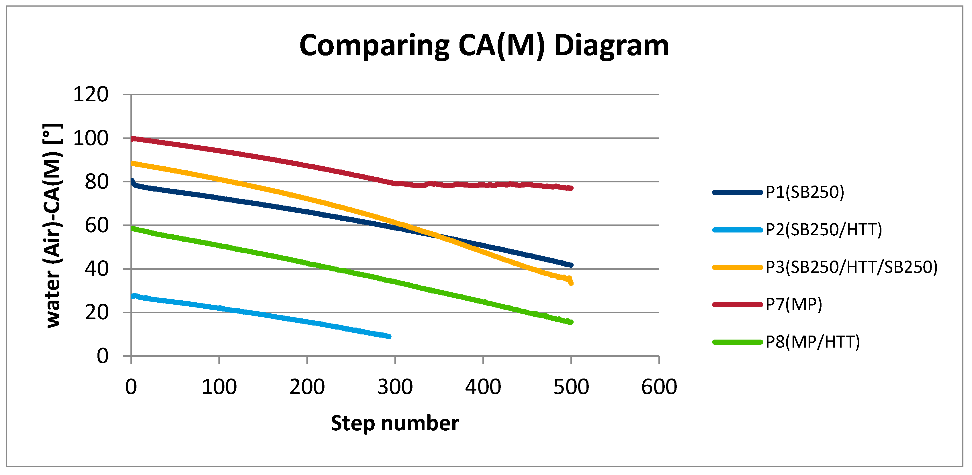
| Types of Surfaces | First Step CA(M) | Steps | Last Step CA(M) | Average CA(M) | ΔCA(M) |
|---|---|---|---|---|---|
| SB250 P1 and P5 (Figure 10a) | 80.52 | 300 | 58.80 | 61.67 (±10.58) | 21.72 |
| SB250/HTT P2 and P6 (Figure 10b) | 27.46 | 300 | 9.00 | 18.81 (±5.33) | 18.46 |
| SB250/HTT/SB250 P3 and P4 (Figure 10c) | 88.48 | 300 | 61.23 | 64.80 (±16.00) | 27.25 |
| MP P7 and P10 (Figure 10d) | 99.50 | 300 | 80.45 | 85.60 (±7.50) | 19.05 |
| MP/HTT P8 and P9 (Figure 10e) | 58.59 | 300 | 34.16 | 37.82 (±12.44) | 24.43 |
Disclaimer/Publisher’s Note: The statements, opinions and data contained in all publications are solely those of the individual author(s) and contributor(s) and not of MDPI and/or the editor(s). MDPI and/or the editor(s) disclaim responsibility for any injury to people or property resulting from any ideas, methods, instructions or products referred to in the content. |
© 2025 by the authors. Licensee MDPI, Basel, Switzerland. This article is an open access article distributed under the terms and conditions of the Creative Commons Attribution (CC BY) license (https://creativecommons.org/licenses/by/4.0/).
Share and Cite
Uriciuc, W.-A.; Suciu, M.; Barbu-Tudoran, L.; Botean, A.-I.; Chicinaș, H.F.; Anghel, M.-A.; Popa, C.O.; Ilea, A. Surface Treatments on Cobalt–Chromium Alloys for Layering Ceramic Paint Coatings in Dental Prosthetics. Coatings 2025, 15, 833. https://doi.org/10.3390/coatings15070833
Uriciuc W-A, Suciu M, Barbu-Tudoran L, Botean A-I, Chicinaș HF, Anghel M-A, Popa CO, Ilea A. Surface Treatments on Cobalt–Chromium Alloys for Layering Ceramic Paint Coatings in Dental Prosthetics. Coatings. 2025; 15(7):833. https://doi.org/10.3390/coatings15070833
Chicago/Turabian StyleUriciuc, Willi-Andrei, Maria Suciu, Lucian Barbu-Tudoran, Adrian-Ioan Botean, Horea Florin Chicinaș, Miruna-Andreea Anghel, Cătălin Ovidiu Popa, and Aranka Ilea. 2025. "Surface Treatments on Cobalt–Chromium Alloys for Layering Ceramic Paint Coatings in Dental Prosthetics" Coatings 15, no. 7: 833. https://doi.org/10.3390/coatings15070833
APA StyleUriciuc, W.-A., Suciu, M., Barbu-Tudoran, L., Botean, A.-I., Chicinaș, H. F., Anghel, M.-A., Popa, C. O., & Ilea, A. (2025). Surface Treatments on Cobalt–Chromium Alloys for Layering Ceramic Paint Coatings in Dental Prosthetics. Coatings, 15(7), 833. https://doi.org/10.3390/coatings15070833