Article

Numerical Analysis of Impingement Jet Combined Cooling with Film Cooling Holes and Thermal Barrier Coatings Using the Decoupling Method

School of Mechanical Engineering and Mechanics, Xiangtan University, Xiangtan 411105, China
*
Author to whom correspondence should be addressed.
Coatings 2025, 15(7), 832; https://doi.org/10.3390/coatings15070832
Submission received: 30 May 2025 / Revised: 7 July 2025 / Accepted: 15 July 2025 / Published: 16 July 2025
(This article belongs to the Section Ceramic Coatings and Engineering Technology)

Abstract

This study investigates the impact of thermal barrier coatings (TBCs) on the individual contributions of cooling components in impingement-jet combined cooling under low Reynolds number conditions. Using decoupled methods, numerical simulations were conducted for cylindrical, fan-shaped, and conical hole geometries. The results show that without TBCs, the conical hole provides the best cooling performance, while the fan-shaped hole performs the worst. After applying TBCs, the cooling effectiveness of the cylindrical and conical holes remains largely unchanged, but the fan-shaped hole shows significant improvement, with performance comparable to the conical hole. The cylindrical hole keeps a uniform shape, leading to increased velocity and preventing stable film formation. In contrast, the expanding flow passages of the fan-shaped and conical holes promote a gradual decrease in flow velocity, supporting stable film formation and effective thermal protection. Impingement cooling accounts for more than 75% of the overall cooling effectiveness for across hole types. For cylindrical and conical holes, the TBCs primarily enhance in-hole cooling, while for the fan-shaped hole, it increases in-hole cooling effectiveness and shifts film cooling effectiveness from negative to positive, significantly improving its overall contribution.

1. Introduction

High-altitude flight conditions offer substantial advantages for both military and commercial aviation applications [1]. Consequently, the development of aircraft capable of operating at elevated altitudes has attracted growing research interest. For example, the long endurance UAV (Unmanned Aerial Vehicle) developed by Romeo et al. [2] can cruise at altitudes ranging from 17 to 20 km, while the propulsion system proposed by Ji et al. [3] is designed to operate at altitudes up to 27.5 km. At such heights, the air density significantly decreases, resulting in turbine operation under low Reynolds number conditions, with values as low as 2 × 10⁴ [4]. These low-Reynolds-number environments typically lead to reduced aerodynamic and thermal performance of turbine components, requiring higher turbine inlet temperatures to maintain the necessary thrust [5]. As a result, enhanced thermal protection and cooling strategies for turbine blades under low Reynolds number conditions are critically important.
Impingement-jet combined cooling is widely recognized as an effective internal cooling technique for modern aero-engine turbines [6,7]. In this approach, coolant first impinges on the inner surface of turbine components, followed by convective heat transfer through cooling holes and subsequent external surface film coverage for additional protection [8]. To better understand the cooling mechanism under low-Reynolds-number conditions, it is essential to decouple and quantify the respective contributions of impingement cooling, internal convective cooling, and external film cooling. Several methods have been proposed for this purpose. Mensch et al. [9] evaluated the effects of film and impingement cooling but did not isolate the contribution of internal convection. Liu et al. [10] used adiabatic walls to separate the cooling components but neglected the influence of coolant temperature rise. Terrell et al. [11] introduced a coolant temperature rise ratio to estimate the convective contribution from leading-edge film cooling holes. A more robust decoupling method was proposed by Bryant et al. [12], who treated the film hole exit as a boundary to isolate external film cooling. Chen et al. [13] further validated the effectiveness of this method in separating internal and external cooling effects.
Among the many factors influencing film cooling performance, hole geometry plays a particularly important role. Conventional cylindrical holes often provide limited lateral coverage and relatively low average cooling effectiveness [14]. Goldstein et al. [15] demonstrated that fan-shaped holes offer significantly improved film cooling performance compared to cylindrical ones. Wang et al. [16] found that, at a blowing ratio of 1.2, fan-shaped and other shaped holes yielded average cooling efficiencies 60.3% and 69.8% higher, respectively, than those of cylindrical holes. Moreover, fan-shaped holes are easier to manufacture than shaped holes and are therefore more commonly used. Jiang et al. [17] showed that conical holes with axial divergence angles provide higher cooling effectiveness and a more stable flow field than cylindrical or fan-shaped holes. However, at low blowing ratios, cylindrical holes may outperform fan-shaped holes along the centerline [16]. Therefore, the selection of hole geometry should consider both operating conditions and the interaction among different cooling mechanisms.
Thermal barrier coatings (TBCs) represent another critical strategy to protect turbine components from elevated gas temperatures. A typical TBC system consists of a top coat (TC), thermally grown oxide (TGO), bond coat (BC), and substrate (SUB), offering low thermal conductivity and high durability [18,19]. TBCs are widely used in gas turbines for aviation, power generation, and marine propulsion, providing thermal insulation for metal components exposed to hot gas flows [20,21]. When TBCs are applied in conjunction with impingement-jet cooling, the resulting heat transfer behavior becomes more complex due to interaction between internal and external convective processes [22]. Tan et al. [23] conducted a conjugate heat transfer analysis to evaluate the influence of TBC thickness on film cooling performance and found that TBCs reduce surface heat transfer. Additionally, the application of TBCs alters the geometry of cooling holes and the injection angle of the coolant, which may further affect the cooling performance [24]. Therefore, quantifying the individual contributions of each cooling component in the presence of TBCs are essential to understand their impact on the overall cooling mechanism.
To address the challenge of quantifying the individual contributions of each cooling component in the presence of thermal barrier coatings (TBCs), the present study employs the decoupled method proposed by Bryant et al. [12] to perform numerical simulations of impingement-jet combined cooling at low Reynolds numbers for three different cooling hole geometries: cylindrical, fan-shaped, and conical. The influence of TBCs on the cooling performance of each component is systematically investigated. The findings aim to enhance our understanding of the combined effects of TBCs and hole geometry on turbine blade cooling, thereby providing valuable guidance for hole design and TBC application under low-Reynolds-number operating conditions.

2. Numerical Methods

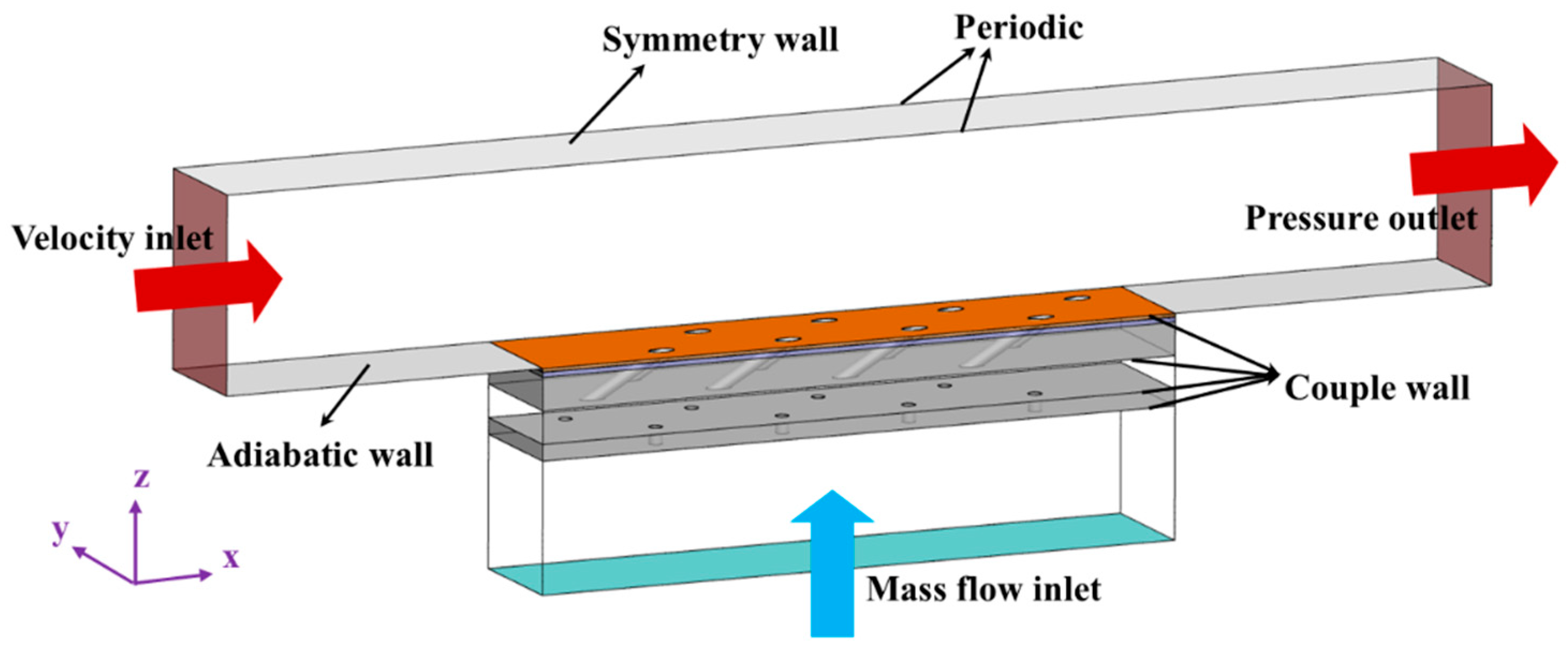
2.1. Numerical Model

The impingement–jet combined cooling model used in this study is illustrated in Figure 1. The model comprises both fluid and solid domains. The solid region includes the impingement plate, the film plate, and the thermal barrier coatings (TBCs). Two staggered rows of film cooling holes are arranged on the film plate, with four holes per row and an inclination angle of 30°. Corresponding impingement holes are placed on the impingement plate in a staggered configuration, perpendicular to the surface (90° inclination). All holes have a diameter D = 0.4 mm, with a spanwise pitch of 5 D and a streamwise pitch of 10 D.
Figure 2 shows the three film hole geometries considered in this study under bare-metal (uncoated) conditions: cylindrical holes (CYHs), fan-shaped holes (FSHs), and conical holes (COHs). Detailed geometric parameters are provided in Table 1. For the coated case, three TBC layers—top coat (TC), thermally grown oxide (TGO), and bond coat (BC)—are applied to the outer surface of the film plate, with respective thicknesses of 150 μm, 10 μm, and 100 μm. A TBC-parallel model is adopted, which assumes that the coating process is completed prior to drilling the film cooling holes [24]. This results in a modified hole length and the cross-sectional area of the outlet due to coating buildup.

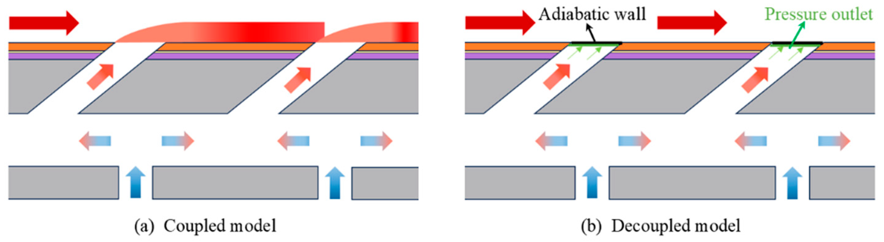
2.2. Boundary Conditions of Coupling Situation and Decoupling Method

A conjugate heat transfer (CHT) approach is used to investigate the overall cooling performance under low-Reynolds-number conditions, providing guidance for turbine cooling during high-altitude operation. The boundary conditions are shown in Figure 3. The characteristic length is set as the axial chord of the cascade blade (100 mm), and the target Reynolds number is 2 × 10⁴, yielding a local Reynolds number based on the hole diameter of 80 [4,13,25]. For the fluid domain, the mainstream inlet (left boundary) is defined as a velocity inlet with a temperature of 733 K. The corresponding velocity for Re = 2 × 10⁴ is 6.5 m/s. The outlet (right boundary) is set to a static pressure of 300,000 Pa. The coolant is introduced via a mass flow inlet at 300 K. The coolant mass flow rate corresponds to a blowing ratio M = 0.5 for the cylindrical hole case and is kept consistent across all hole types. Periodic boundary conditions are applied on the lateral sides in the pitchwise direction for both fluid and solid domains. The interface between the fluid and solid domains is treated as a coupled boundary, while all other walls are set to adiabatic. The working fluid is modeled as an ideal, incompressible gas. Perfect thermal contact is assumed between solid layers, and interfacial thermal resistance is neglected. The film and impingement plates are made of IC10 alloy, with temperature-dependent thermal conductivity is expressed as follows: ks = 0.6947 + 0.021 T [W/(m·K)], T ∈ [400, 1500] [25]. For coated cases, the material properties of each TBC layer are listed in Table 2, where the thermal conductivity of the BC is also temperature dependent.
The overall cooling effectiveness ϕ under conjugate heat transfer is defined as follows:
ϕ = T g T w T g T c ,
where Tg is the mainstream inlet temperature, Tw is the wall temperature on the gas-side surface of the film plate, and Tc is the coolant inlet temperature.
To isolate the contributions of individual cooling mechanisms, the decoupling method proposed by Bryant et al. [12] is adopted. Taking the coated cylindrical hole case as an example, Figure 4 illustrates the boundary settings for the decoupling model. Figure 4b shows the internal cooling model used to isolate external film cooling. In this model, the hole exit plane facing the film surface is treated as an adiabatic wall, while the inner exit face is set as a pressure outlet. This configuration effectively excludes the influence of external film cooling while maintaining the internal coolant flow pattern. The resulting cooling effectiveness, referred to as the decoupled internal cooling effectiveness φdec, includes contributions from impingement and internal convection, and is calculated as follows [27]:
ϕ d e c = T g T w , d e c T g T c ,
where Tw,dec is the wall temperature obtained from the decoupled model.
Additionally, the relative contributions of impingement and internal convection are estimated using the temperature rise ratio between the coolant inlet and hole outlet, following the method of Terrell et al. [11]. The external film cooling effectiveness φext is then obtained by subtracting φdec, from the overall effectiveness ϕ [27].
ϕ e x t = ϕ ϕ d e c .

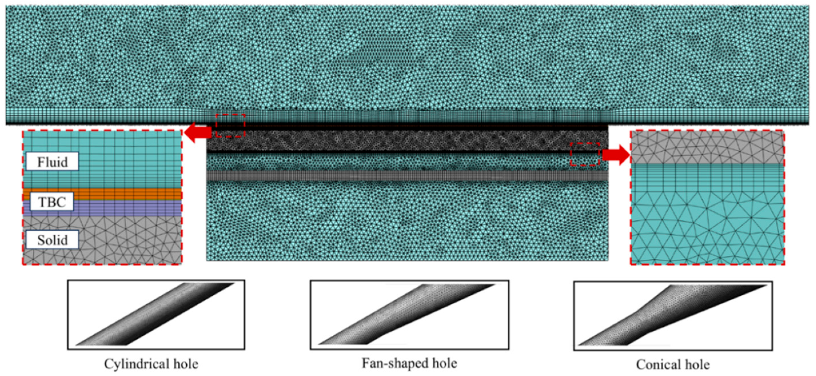
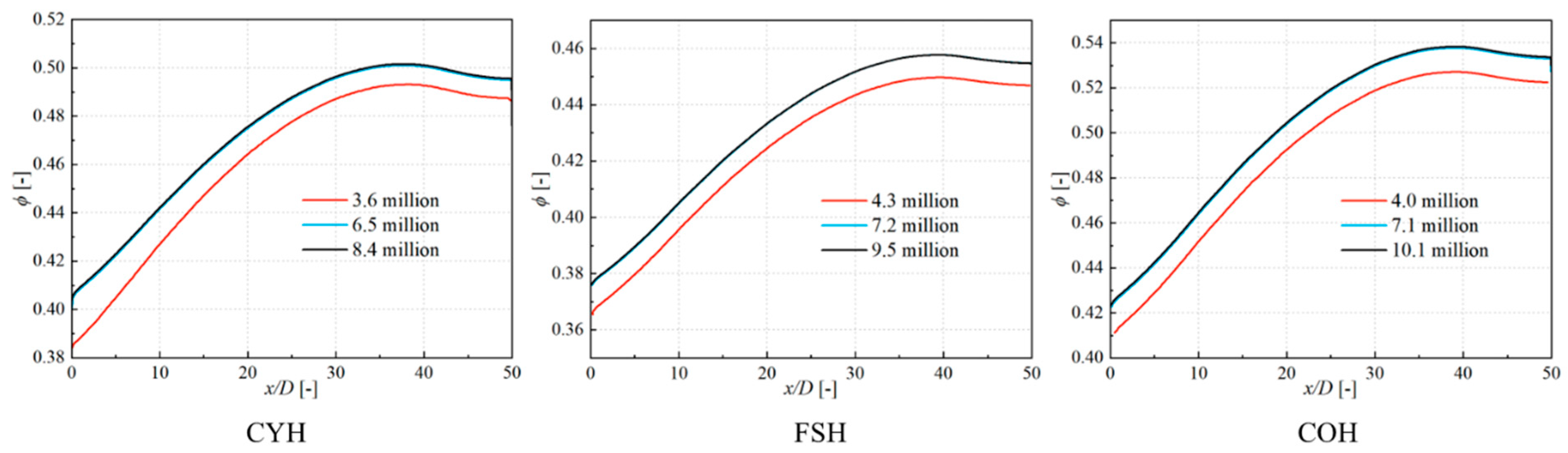
2.3. Grid and Turbulence Model

Unstructured meshes for the computational domain are generated using ANSYS Meshing, as shown in Figure 5. Boundary layer grids are applied at fluid-solid interfaces with a growth rate of 1.2, ensuring a y+ value close to 1. A mesh independence study is conducted using the three-hole models by refining mesh density near film holes, impingement holes, and coupled interfaces. Figure 6 compares the centerline cooling effectiveness of three models on the gas-side film plate surface among the three meshes. The results show that the medium and high mesh configurations all have nearly identical results, with a maximum relative deviation of less than 0.5%. Thus, the 6.5 M, 7.2 M, and 7.1 M mesh configurations are adopted for subsequent simulations of three-hole models to balance accuracy and computational efficiency.
This study is based on the assumptions of steady-state, incompressible flow and uses the Reynolds-Averaged Navier–Stokes (RANS) equations to describe turbulent flow. The governing equations are as follows [25]:
ρ t + ρ x i ρ u i ¯ = 0 ,
D u i D t = P ¯ x i + x i μ i u i ¯ x j + u j ¯ x i 2 3 δ i j ρ k + x j ρ u i ¯ u j ¯ = 0 , and
x i ρ u i ¯ T ¯ = x i μ P r + μ t P r t T ¯ x i ,
where μ, μt, and Prt represent turbulent viscosity, turbulent kinetic energy, and turbulent Prandtl number, respectively.
The choice of turbulent model has a critical impact on the reliability of cooling structure calculations. In this study, numerical simulations were conducted using ANSYS Fluent, which provides various turbulence models, including the SST k-ω model and the Realizable k-ε model. To verify the accuracy of the results, simulations were performed for the film cooling structure at a blowing ratio M = 1.0 from Li et al. [28] using both the SST k-ω and Realizable k-ε models. Figure 7 shows a comparison of the lateral-averaged cooling effectiveness between the experimental data and the results from both turbulence models. The results indicate that the Realizable k-ε model provides a better match with the experimental data, with the largest error observed in the downstream region being 0.013. Therefore, the Realizable k-ε model was selected for the turbulence modeling in the numerical simulations.
The turbulence kinetic energy k and turbulence dissipation rate ε equations for the Realizable k-ε model are as follows:
t ρ k + x i ρ k u j = x j μ + μ t σ k k x j + P k + P b ρ ε Y M + S k and
t ρ ε + x i ρ ε u j = x j μ + μ t σ ε ε x j + ρ C 1 S ε ρ C 2 ε 2 k + v ε Y M + C 1 ε ε k S 3 ε P b + S ε
where Sk and Sε are user-defined source terms.

3. Discussion

3.1. Comparison of the Overall Cooling Performance

This section analyzes the numerical simulation results of the coupled model for a composite cooling structure under low Reynolds number conditions. Figure 8 shows the overall cooling effectiveness distribution on the film-cooled flat plate surface for three different hole types: cylindrical, conical, and fan-shaped, with and without surface TBCs. The results indicate that, without TBCs, the conical hole provides the best cooling performance, while the fan-shaped hole shows the least effectiveness. After TBCs are applied, the cooling effectiveness of both cylindrical and conical holes changes little. However, the fan-shaped hole shows a significant improvement, achieving performance similar to that of the conical hole.
Figure 9 depicts the lateral-averaged overall cooling effectiveness along the streamwise direction for each case. It can be observed that all three hole geometries exhibit a similar trend in effectiveness variation along the flow direction. Specifically, compared to the cylindrical hole, the fan-shaped hole shows a maximum cooling effectiveness that is 8.72% lower without TBCs, while the conical hole demonstrates an increase of 7.27% without TBCs. The influence of the coating on cylindrical and conical holes is relatively moderate, mainly contributing to a slight overall enhancement in cooling effectiveness. This is particularly evident in the upstream region (0 < x/D < 30), where the growth rate of effectiveness slows, resulting in more uniform cooling. In contrast, TBCs have a more pronounced effect on the fan-shaped hole. After TBCs are applied, the maximum cooling effectiveness increases from 0.458 to 0.541, representing an 18.12% improvement. This significant enhancement not only elevates the overall cooling performance but also brings the downstream performance of the fan-shaped hole close to that of the conical hole, demonstrating the potential advantage of TBCs in optimizing non-axisymmetric hole cooling structures. In summary, the introduction of TBCs effectively enhances local cooling effectiveness, with particularly notable benefits for the fan-shaped hole configuration. These findings suggest that, in practical applications, an optimized combination of hole geometry and TBCs can substantially improve the performance of film cooling systems under low Reynolds number conditions, providing theoretical support and design guidance for efficient thermal protection of gas turbine components and other high-temperature parts.

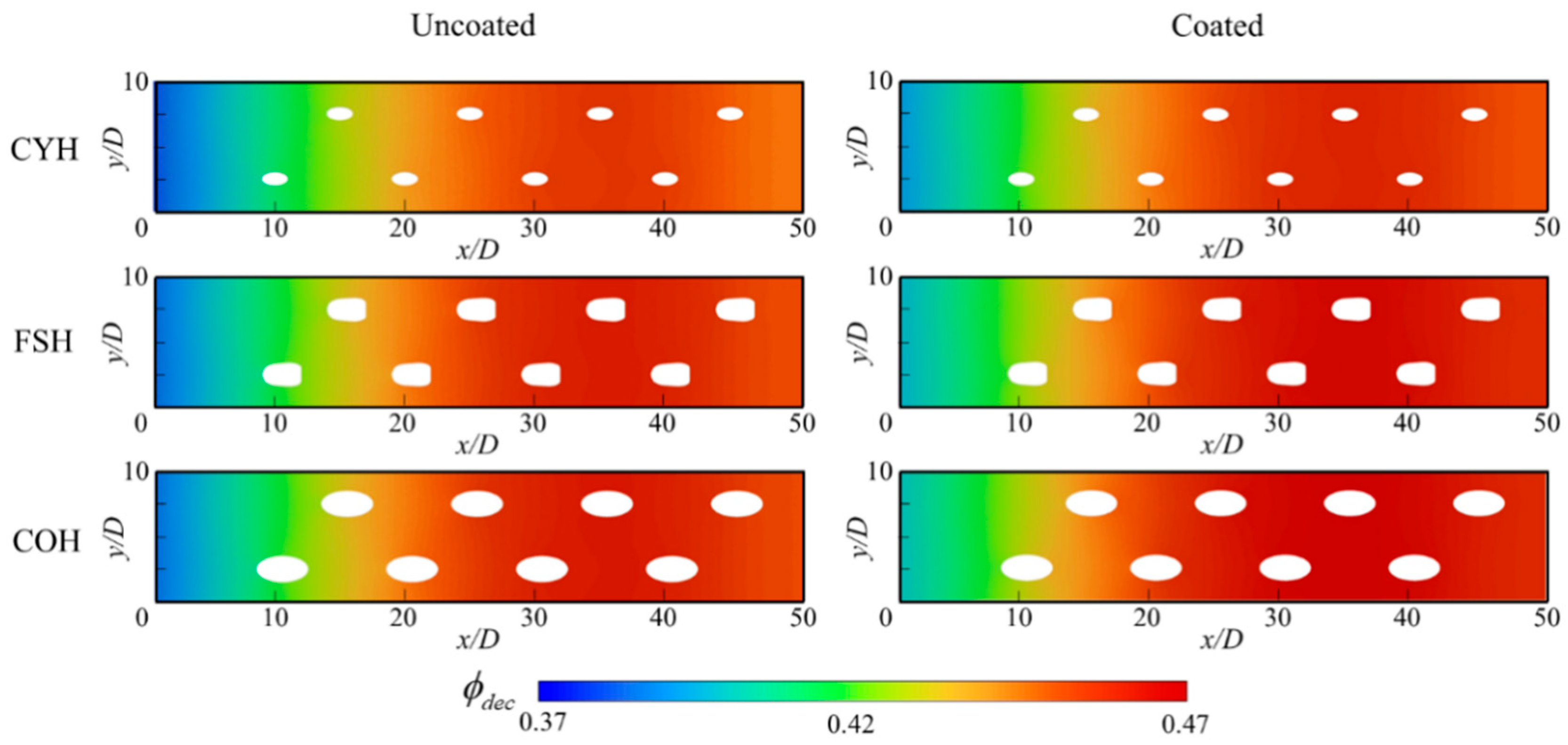
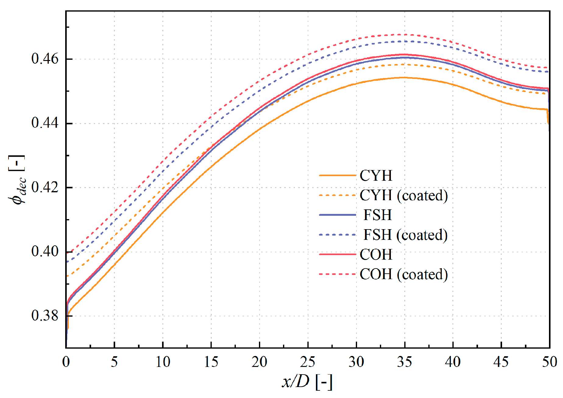
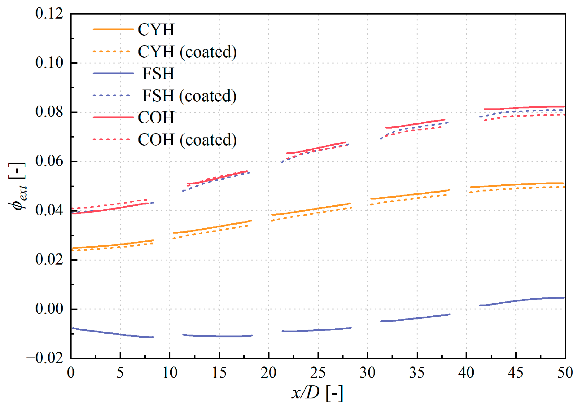
3.2. Influence on the Inner and Outer Cooling Performance

This section presents a detailed numerical analysis of the decoupled model for composite cooling structures under low-Reynolds-number conditions. The results are compared with the coupled model to evaluate internal and external cooling performance across different hole geometries. Figure 10 illustrates the distribution of internal cooling effectiveness on the film-cooled plate for three hole configurations with and without TBC coverage. It is observed that both the fan-shaped and conical holes yield slightly higher internal cooling effectiveness compared to the cylindrical hole. The presence of TBC generally enhances the internal cooling effectiveness across the entire surface. Moreover, the internal cooling distribution is relatively uniform in the spanwise direction for all cases.
Figure 11 illustrates the streamwise variation of internal cooling effectiveness along the plate centerline (y/D = 5). For all configurations, the maximum internal effectiveness occurs around x/D = 35. Without TBCs, the internal cooling effectiveness of the fan-shaped and conical holes is nearly identical in the upstream but diverges progressively downstream from the cylindrical hole case. The influence of the coating is consistent across all three hole types, with a reduced growth rate of cooling effectiveness in the upstream region (0 < x/D < 10), indicating a smoother thermal transition. However, the conical hole exhibits the most pronounced improvement, with the maximum effectiveness increasing by 1.36% due to TBCs.
Figure 12 presents the external cooling effectiveness along the hole centerline (y/D = 2.5). In the absence of TBCs, the external effectiveness for the cylindrical and conical holes shows a similar increasing trend along the mainstream direction, but the conical hole achieves significantly higher effectiveness, with the performance gap widening downstream. The fan-shaped hole, however, demonstrates a non-monotonic trend, initially decreasing and then increasing. Notably, it exhibits negative cooling effectiveness in the region 0 < x/D < 40, indicating that the wall temperature exceeds that of the cooling film—an undesirable effect. With TBC’s application, the cylindrical hole sees a slight overall decrease in external effectiveness. For the conical hole, a minor improvement is observed in the upstream region (0 < x/D < 10), a negligible change in the midstream region (10 < x/D < 20), and a gradual reduction downstream (20 < x/D < 50). In contrast, the TBCs have a transformative impact on the fan-shaped hole: it eliminates the negative cooling zone and aligns its external effectiveness in magnitude and trend with that of the conical hole.
To further understand the cooling performance differences induced by hole geometry, Figure 13 and Figure 14 display the velocity and temperature fields around the film-cooled plate at the y = 2.5 D cross-section under coupled conditions. Among the three geometries, the cylindrical hole-with its constant cross-sectional area-produces the highest exit velocity due to maintained flow momentum. In contrast, the expanding structure of the conical and fan-shaped holes leads to decelerated internal flow and thicker boundary layers, especially pronounced in the conical hole’s divergent section. Near-wall temperature distributions reveal steeper thermal gradients for the conical and fan-shaped holes compared to the cylindrical hole. This is attributed to the inability of high-velocity coolant jets from cylindrical holes to form a coherent thermal film, resulting in direct mixing with the hot mainstream. Conversely, the conical hole promotes the formation of a thin, low-temperature film close to the wall, providing superior thermal protection. However, the fan-shaped hole still exhibits negative cooling effectiveness in the upstream region due to adverse flow interactions.
As shown in Figure 14, during internal cooling, the fan-shaped hole exhibits greater heat transfer rates, with significantly higher coolant temperature rise compared to the other two geometries. This suggests more intense convective heat exchange within the fan-shaped passage, potentially linked to complex flow separation and recirculation patterns. Figure 15 compares the temperature fields across the film-cooled plate cross-section for the fan-shaped hole under coupled and decoupled conditions. In the decoupled model, the plate temperature is found to be lower than the coolant film temperature, indicating that the coolant film may act as a heat source rather than a sink under certain coupled scenarios. This highlights a key limitation of fan-shaped holes in the absence of a thermal barrier coating. Among the three geometries, TBCs have the most profound effect on the fan-shaped hole, both in terms of internal and external cooling performance. A clearer understanding of this effect is achieved by analyzing the cross-sectional temperature fields within the solid. As shown in Figure 15, TBCs increase the temperature discrepancy between coupled and decoupled models, implying enhanced external film cooling. TBCs also reduce the temperature gradient along the mainstream direction, promoting more uniform cooling. Most importantly, in the upstream region, TBCs eliminate the negative film cooling effect previously observed.
Figure 16 presents the velocity field around the film hole in the upstream region with and without TBCs. It can be seen that the presence of the coating reduces the flow velocity inside the hole. This is attributed to the extended hole length caused by the coating layer. In the extended section, the insulating effect of the TBCs reduces the vertical velocity gradient near the wall, resulting in a more uniform exit velocity. The coolant forms a stable film on the coated surface, providing a dual thermal protection mechanism—from both the coolant and the TBCs—thus significantly enhancing external cooling effectiveness.
Figure 17 shows the temperature contour at the mainstream cross-section of x = 17.5 D. As can be seen in the figure, the cylindrical hole jet has the highest trajectory and deepest penetration depth, but with the narrowest width. The fan-shaped hole jet exhibits a lower height due to its structure-induced rapid kinetic energy dissipation. The conical hole jet demonstrates the widest spread, providing broader cooling coverage.

3.3. Influence on the Contributions of the Three Cooling Components

This section provides a quantitative analysis of the cooling performance of composite cooling structures. It further explores the contributions of individual cooling components to the overall cooling effectiveness. Table 3 lists the overall cooling effectiveness and the average contributions from the three primary cooling components (impingement cooling, in-hole cooling, and film cooling) across different cooling configurations. It is clear that the overall cooling effectiveness of the impingement-jet combined cooling structure is influenced by the contributions of different cooling components under low-Reynolds-number conditions. Specifically, impingement cooling contributes the most to the overall cooling effectiveness, with a contribution exceeding 75% for all three hole configurations. This indicates that impingement cooling plays a dominant role in cooling performance under low-Reynolds-number flow conditions. The effect of TBCs on the cooling effectiveness varies across different hole types. For the cylindrical and conical holes, the addition of TBCs primarily enhance in-hole cooling effectiveness, while the contributions of the other cooling components remain largely unchanged. Specifically, TBCs increase the in-hole cooling effectiveness from 0.046 to 0.052 for the cylindrical hole and from 0.051 to 0.065 for the conical hole. Figure 18 and Figure 19 show the wall temperature distribution along the height of the film holes and the coolant temperature distribution inside the holes, respectively. The thermal insulation effect of the coating reduces both the wall temperature and the coolant temperature within the holes. However, the extended flow path due to the coating increases the coolant’s temperature rise inside the holes, thereby enhancing the contribution of in-hole cooling within internal cooling. This suggests that the TBC improves internal airflow and heat transfer, thereby enhancing overall cooling effectiveness. However, the impact of the TBC on the fan-shaped hole is more significant. Without TBCs, the film cooling effectiveness of the fan-shaped hole is negative (−0.007), meaning that the coolant film does not effectively protect the plate surface and instead exacerbates heat transfer. Consistent with the phenomena observed in simulations by Chen et al. [13], under extremely low-Reynolds-number conditions, the intensified lift-off effect of film cooling combined with enhanced internal cooling from fan-shaped holes leads to significant coolant temperature rise, resulting in negative film cooling effectiveness. The introduction of the coating changes this situation, turning the film cooling effectiveness positive (0.061), and the contribution of this cooling component increases significantly. This indicates that the coating not only eliminates the negative cooling effect but also optimizes the thermal insulation provided by the film cooling.
Figure 20 clearly shows how TBCs affect the contribution proportions of each cooling component. The data reveal that TBCs primarily enhance the in-hole cooling contribution for both cylindrical and conical holes, with minimal impact on the contributions from film cooling and impingement cooling. Specifically, for the cylindrical and conical hole configurations with coating, the film cooling contribution increases from 9.73% and 10.16% to 10.09% and 12.74%, respectively. This suggests that TBCs improve the effectiveness of film cooling but do not alter the dominant role of impingement cooling. For the fan-shaped hole, the changes in the contributions of each cooling component are more complex. After coating, the contribution of film cooling changes from a negative value (−1.62%) to a positive value (12.03%), while the contribution of impingement cooling decreases. This reflects that the coating’s optimization of the film cooling effect while slightly affecting the effectiveness of impingement cooling. The in-hole cooling contribution increases, further indicating that the coating improves the overall effectiveness of the cooling system. Further analysis shows that the coating’s effect on cooling effectiveness improvement varies significantly across different hole types. For the cylindrical and conical holes, the addition of the coating increases the overall cooling effectiveness by approximately 0.004 (from 0.473 to 0.477) and 0.008 (from 0.502 to 0.510), respectively. Although these improvements are modest, the TBCs’ optimization of the cooling system, especially by enhancing in-hole cooling effectiveness, should not be underestimated. In contrast, the effect of the TBC on the fan-shaped hole is more pronounced, with the overall cooling effectiveness increasing from 0.432 to 0.507, a remarkable increase of 18.12%. This improvement is primarily attributed to the positive shift in film cooling effectiveness and the enhancement of in-hole cooling effectiveness. TBC causes the cooling performance of the fan-shaped hole to approach that of the conical hole, and the significant improvement in cooling effectiveness enhances the thermal protection capability of the plate surface. In summary, TBCs have a significant impact on the overall cooling performance of composite cooling structures under low-Reynolds-number conditions, especially for the fan-shaped hole. TBCs change the negative cooling effect of film cooling and enhance the effectiveness of in-hole cooling. By analyzing the cooling performance of the three hole types before and after coating application, the contributions of TBC to different cooling components and its role in enhancing overall cooling effectiveness are clearly quantified. These findings provide valuable insights for the design and optimization of hole configurations and coatings in practical applications.

4. Conclusions

To address the challenge of quantifying the individual contributions of each cooling component in the presence of thermal barrier coatings (TBCs), this study uses the decoupled methods to perform numerical simulations of impingement-jet combined cooling under low-Reynolds-number conditions. The simulations focus on cylindrical, fan-shaped, and conical hole geometries. The main conclusions are as follows:
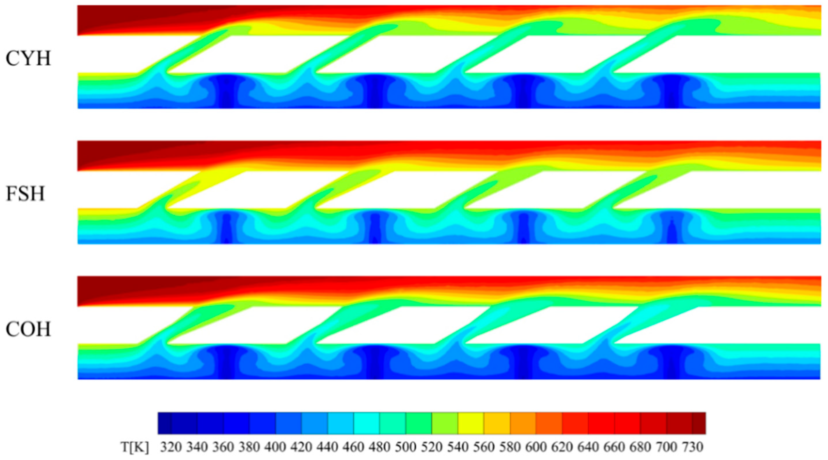
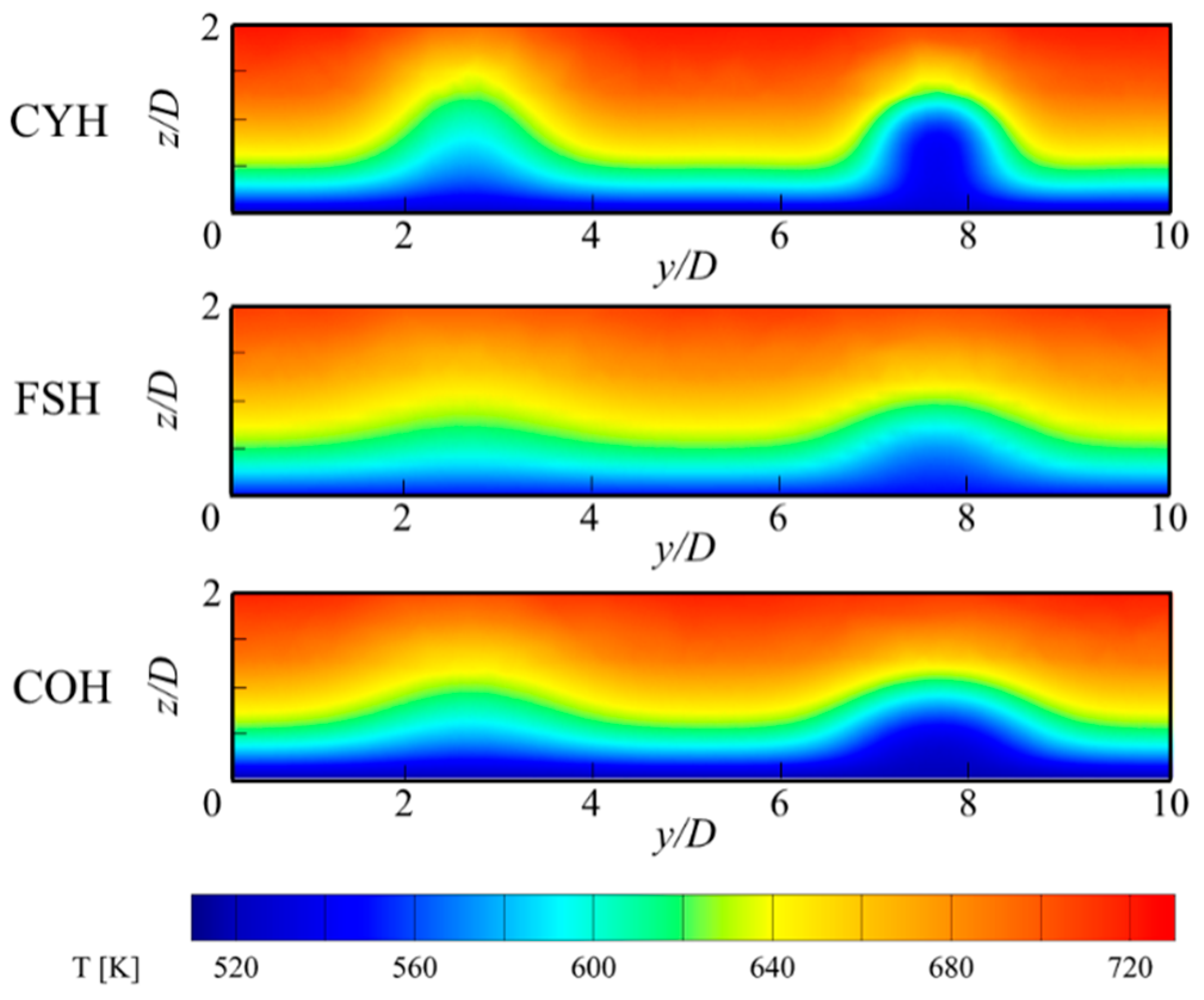
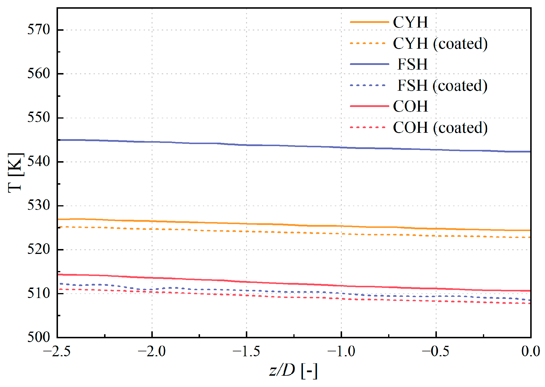
  • Without TBCs, the conical hole provides the best cooling performance on the film-cooled flat plate, while the fan-shaped hole performs the worst. After applying the TBCs, the cooling effectiveness of the cylindrical and conical holes changes little, but the fan-shaped hole shows a significant improvement, with its cooling performance becoming comparable to that of the conical hole.
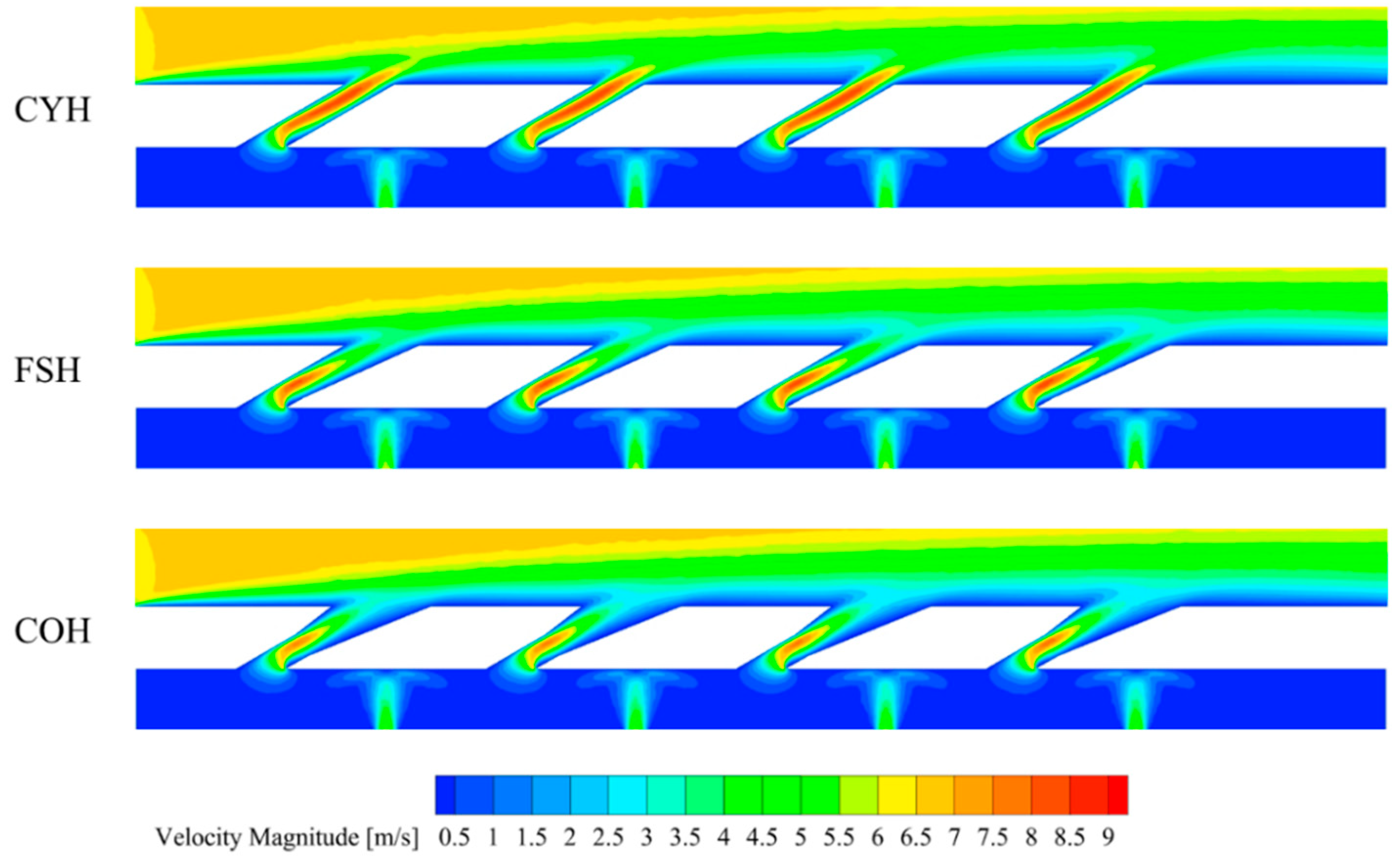
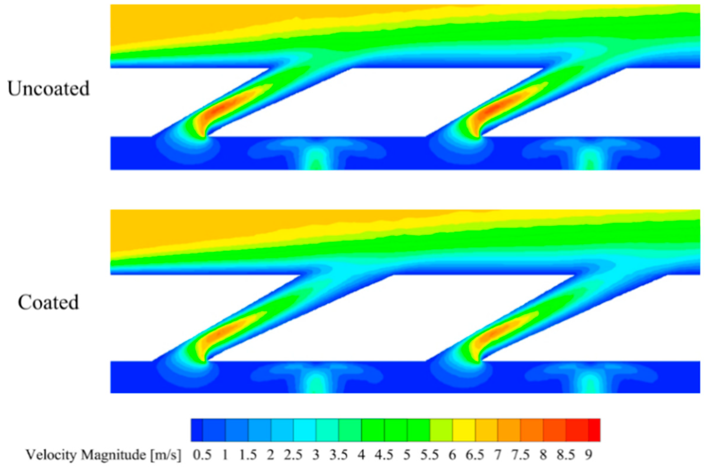
  • The cylindrical hole has a constant cross-sectional area, resulting in the highest flow velocity at the hole exit, which is unfavorable for forming a stable coolant film. In contrast, the fan-shaped and conical holes feature expanding flow passages, leading to a gradual decrease in flow velocity. This helps to form a stable film near the wall, providing effective thermal protection.
  • The contribution of impingement cooling accounts for more than 75% of the overall cooling effectiveness across all three hole types. For the cylindrical and conical holes, the improvement in cooling effectiveness due to the TBCs is primarily attributed to in-hole cooling. For the fan-shaped hole, the impingement cooling effectiveness decreases, while the in-hole cooling and film cooling effectiveness increase, leading to a significant rise in its contribution.

Author Contributions

In this paper, S.L. and L.S. carried out the simulations and wrote this paper. X.T., C.W., Y.L., R.D., H.Z., C.Z. and J.P. improved the discussions and the paper overall. All authors have read and agreed to the published version of the manuscript.

Funding

This research was funded by the National Natural Science Foundation of China, grant number 51806184, and the Natural Science Foundation of Hunan Province, grant number 2019JJ50590.

Institutional Review Board Statement

Not applicable.

Informed Consent Statement

Not applicable.

Data Availability Statement

Data are contained within the article.

Conflicts of Interest

The authors declare no conflicts of interest.

Nomenclature

DDiameter of the cylindrical hole [mm]
LLength of film hole [mm]
LfExpansion section length film hole [mm]
RCorner radius [mm]
kThermal conductivity [W/(m·K)]
TgMainstream inlet temperature [K]
TwTemperature of the coupling surface [K]
Tw,decTemperature of the decoupling surface [K]
TcCoolant inlet temperature [K]
MBlowing ratio [-]
ϕOverall cooling effectiveness [-]
ϕdecDecoupled internal cooling effectiveness [-]
ϕextExternal film cooling effectiveness [-]
ϕimpImpingement cooling effectiveness [-]
ϕinholeIn-hole cooling effectiveness [-]
βLateral divergence angle [°]
Abbreviations
BCBond coat
CHTConjugate heat transfer
COHConical holes
CYHCylindrical holes
FSHFan-shaped holes
TBCThermal barrier coating
TCTop coat
TGOThermally grown oxide
Superscripts
Lateral averaged value
=Area averaged value

References

  1. Van Treuren, K.W.; McClain, S.T. The Challenges of High Altitude Gas Turbine Engine Cycles. In Proceedings of the ASME Turbo Expo 2010: Power for Land, Sea, and Air, Glasgow, UK, 14–18 June 2010; pp. 367–378. [Google Scholar]
  2. Romeo, G.; Frulla, G. Heliplat®: High altitude very-long endurance solar powered UAV for telecommunication and Earth observation applications. Aeronaut. J. 2004, 108, 277–293. [Google Scholar] [CrossRef]
  3. Ji, Z.; Rokni, M.M.; Qin, J.; Zhang, S.; Dong, P. Energy and configuration management strategy for battery/fuel cell/jet engine hybrid propulsion and power systems on aircraft. Energy Convers. Manag. 2020, 225, 113393. [Google Scholar] [CrossRef]
  4. Mu, C.; Zhang, W.; Wang, J.; Huang, D.; Jiang, C. Low-Reynolds-Number effect on film cooling in Turbines: Jet-induced vortex structures on cooling effectiveness and aerodynamic loss. Appl. Therm. Eng. 2025, 274, 126325. [Google Scholar] [CrossRef]
  5. Jia, Z.; Tang, H.; Jin, D.; Chen, M.; Li, S.; Liu, X. Multifidelity Simulation Research on the Low Reynolds Number Effect on the Engine Performance at Different Altitudes. J. Eng. Gas Turb. Power 2022, 144, 101011. [Google Scholar] [CrossRef]
  6. Chokhar, I.A.; Dyachenko, A.Y.; Pakhomov, M.A.; Philippov, M.V.; Terekhov, V.I. Experimental study of the effect of a transverse trench depth on film cooling effectiveness. Case Stud. Therm. Eng. 2021, 25, 100934. [Google Scholar] [CrossRef]
  7. Wu, H.; Yang, X.; Liu, Z.; Feng, Z. Comparisons between forward- and backward-inclined film injection over an effusion wall with internal jet-array impingement: Cooling effectiveness, heat transfer, and analytical model. Appl. Therm. Eng. 2025, 262, 125280. [Google Scholar] [CrossRef]
  8. Youn, J.-S.; Choi, W.-W.; Kim, S.-M. Numerical investigation of jet array impingement cooling with effusion holes. Appl. Therm. Eng. 2021, 197, 117347. [Google Scholar] [CrossRef]
  9. Mensch, A.; Thole, K.A. Overall Effectiveness of a Blade Endwall with Jet Impingement and Film Cooling. In Proceedings of the ASME Turbo Expo 2013: Turbine Technical Conference and Exposition, San Antonio, TX, USA, 3–7 June 2013. [Google Scholar]
  10. Liu, R.; Li, H.; You, R.; Tao, Z.; Huang, Y. Numerical decoupling of the effect of internal cooling and external film cooling on overall cooling effectiveness. Appl. Therm. Eng. 2023, 222, 119905. [Google Scholar] [CrossRef]
  11. Terrell, E.J.; Mouzon, B.D.; Bogard, D.G. Convective Heat Transfer Through Film Cooling Holes of a Gas Turbine Blade Leading Edge. In Proceedings of the ASME Turbo Expo 2005: Power for Land, Sea, and Air, Reno-Tahoe, NV, USA, 6–9 June 2005; pp. 833–844. [Google Scholar]
  12. Bryant, C.E.; Rutledge, J.L. A Computational Technique to Evaluate the Relative Influence of Internal and External Cooling on Overall Effectiveness. J. Turbomach. 2020, 142, 051008. [Google Scholar] [CrossRef]
  13. Chen, P.; Zhang, D.; Liu, H.; Mao, J. Conjugate heat transfer analysis on composite cooling structure with low Reynolds number using the decoupling method. Case Stud. Therm. Eng. 2024, 61, 105051. [Google Scholar] [CrossRef]
  14. Wang, J.; Ke, T.; Jing, L.; Sundén, B. Effect of hole configurations on film cooling performance. Nume. Heat Transf. A-Appl. 2019, 75, 725–738. [Google Scholar] [CrossRef]
  15. Goldstein, R.J.; Eckert, E.R.G.; Burggraf, F. Effects of hole geometry and density on three-dimensional film cooling. Int. J. Heat Mass Tran. 1974, 17, 595–607. [Google Scholar] [CrossRef]
  16. Wang, J.; Zhao, Z.; Tian, L.; Ren, X.; Sundén, B. Effects of hole configuration on film cooling effectiveness and particle deposition on curved surfaces in gas turbines. Appl. Therm. Eng. 2021, 190, 116861. [Google Scholar] [CrossRef]
  17. Jiang, Y.; Li, H.; Liu, R.; Tao, Z.; Zhou, Z. Film cooling comparison of shaped holes among the pressure surface, the suction surface and the leading edge of turbine vane. Appl. Therm. Eng. 2023, 219, 119343. [Google Scholar] [CrossRef]
  18. Padture, N.P.; Gell, M.; Jordan, E.H. Thermal Barrier Coatings for Gas-Turbine Engine Applications. Science 2002, 296, 280–284. [Google Scholar] [CrossRef] [PubMed]
  19. Evans, A.G.; Mumm, D.R.; Hutchinson, J.W.; Meier, G.H.; Pettit, F.S. Mechanisms controlling the durability of thermal barrier coatings. Prog. Mater. Sci. 2001, 46, 505–553. [Google Scholar] [CrossRef]
  20. Miller, R.A. Oxidation-Based Model for Thermal Barrier Coating Life. J. Am. Ceram. Soc. 1984, 67, 517–521. [Google Scholar] [CrossRef]
  21. Wright, P.K.; Evans, A.G. Mechanisms governing the performance of thermal barrier coatings. Curr. Opin. Solid State Mater. Sci. 1999, 4, 255–265. [Google Scholar] [CrossRef]
  22. Meng, Z.; Liu, Y.; Li, Y.; He, X. The performance evaluation for thermal protection of turbine vane with film cooling and thermal barrier coating. Appl. Therm. Eng. 2022, 210, 118405. [Google Scholar] [CrossRef]
  23. Vo, D.-T.; Mai, T.D.; Kim, B.; Ryu, J. Numerical study on the influence of coolant temperature, pressure, and thermal barrier coating thickness on heat transfer in high-pressure blades. Int. J. Heat Mass Transf. 2022, 189, 122715. [Google Scholar] [CrossRef]
  24. Pi, Y.H.; Park, J.S. Effect of the thermal barrier coating set up and modeling in numerical analysis for prediction gas turbine blade temperature and film cooling effectiveness. Int. Commun. Heat Mass Transf. 2025, 164, 108860. [Google Scholar] [CrossRef]
  25. Zhang, D.; Liu, H.; Chen, P.; Mao, J. Numerical analysis on multiple parameters for overall cooling effectiveness of impingement effusion cooling with low Reynolds number. Int. Commun. Heat Mass Transf. 2024, 153, 107366. [Google Scholar] [CrossRef]
  26. Liu, J.H.; Liu, Y.B.; He, X.; Liu, L. Study on TBCs insulation characteristics of a turbine blade under serving conditions. Case Stud. Therm. Eng. 2016, 8, 250–259. [Google Scholar] [CrossRef]
  27. Zhou, W.; Deng, Q.; He, W.; He, J.; Feng, Z. Conjugate heat transfer analysis for composite cooling structure using a decoupled method. Int. J. Heat Mass Transf. 2020, 149, 119200. [Google Scholar] [CrossRef]
  28. Li, Y.; Zhang, Y.; Su, X.; Yuan, X. Experimental and numerical investigations of shaped hole film cooling with the influence of endwall cross flow. Int. J. Heat Mass Transf. 2018, 120, 42–55. [Google Scholar] [CrossRef]
Figure 1. Schematic of the geometry model.
Coatings 15 00832 g001
Figure 2. Geometry of the shaped holes.
Coatings 15 00832 g002
Figure 3. Boundary conditions of the calculation domain.
Coatings 15 00832 g003
Figure 4. Coupled and decoupled cooling model.
Coatings 15 00832 g004
Figure 5. Grid of cooling configurations.
Coatings 15 00832 g005
Figure 6. Centerline cooling effectiveness for different number of grids for different geometries.
Coatings 15 00832 g006
Figure 7. Comparison of lateral-averaged cooling effectiveness for experiment [28] and different turbulence models.
Coatings 15 00832 g007
Figure 8. Overall cooling effectiveness distributions on the film plate surface.
Coatings 15 00832 g008
Figure 9. Lateral-averaged cooling effectiveness of the film plate surface.
Coatings 15 00832 g009
Figure 10. Inner cooling effectiveness distributions on the film plate surface.
Coatings 15 00832 g010
Figure 11. Centerline inner cooling effectiveness of the film plate surface.
Coatings 15 00832 g011
Figure 12. Outer cooling effectiveness at the line of y/D = 2.5 location.
Coatings 15 00832 g012
Figure 13. Velocity distribution at the y = 2.5 D cross-section under coupled conditions.
Coatings 15 00832 g013
Figure 14. Temperature distribution at the y = 2.5 D cross-section under coupled conditions.
Coatings 15 00832 g014
Figure 15. Temperature distribution across the film plate cross-section for the fan-shaped hole type.
Coatings 15 00832 g015
Figure 16. Velocity distribution near the fan-shaped hole before and after coating.
Coatings 15 00832 g016
Figure 17. Temperature contour at the mainstream cross-section of x = 17.5 D.
Coatings 15 00832 g017
Figure 18. Wall temperature curve of the film holes along the height direction.
Coatings 15 00832 g018
Figure 19. Coolant temperature curve inside the hole along the height direction.
Coatings 15 00832 g019
Figure 20. Effectiveness proportion of the three cooling components.
Coatings 15 00832 g020
Table 1. Geometric parameters of each hole type.
ParametersValue
Diameter of the cylindrical hole D (mm)0.4
Length of film hole L/D (-)5
Shaped length ratio Lf/L (-)2/3
Lateral divergence angle β (°)8
Corner radius R (mm)0.2
Table 2. Material properties [26].
MaterialDensity
(kg/m3)
Temperature
T (°C)
Thermal Conductivity
K (W/m∙K)
TC5650-1.05
TGO3978-25.20
BC7320254.30
4006.40
80010.20
100016.10
Table 3. Average effectiveness of overall cooling and three cooling components.
ϕ ´ ϕ ´ i m p ϕ ´ i n h o l e ϕ ´ e x t
CYH0.4730.3880.0460.039
CYH (coated)0.4770.3880.0520.037
FSH0.4320.3930.046−0.007
FSH (coated)0.5070.3870.0590.061
COH0.5020.3880.0510.063
COH (coated)0.5100.3830.0650.062
Disclaimer/Publisher’s Note: The statements, opinions and data contained in all publications are solely those of the individual author(s) and contributor(s) and not of MDPI and/or the editor(s). MDPI and/or the editor(s) disclaim responsibility for any injury to people or property resulting from any ideas, methods, instructions or products referred to in the content.

