Article

Ni20/PTFE Composite Coating Material and the Synergistic Friction Reduction and Wear Resistance Mechanism Under Multiple Working Conditions

1
School of Mechatronic Engineering, Xi’an Technological University, Xi’an 710021, China
2
State Key Laboratory of Mechanical Transmission for Advanced Equipment, Chongqing University, Chongqing 400044, China
3
School of Information Engineering, Yellow River Water Conservancy Vocational and Technical College, Kaifeng 475004, China
*
Author to whom correspondence should be addressed.
Coatings 2025, 15(7), 830; https://doi.org/10.3390/coatings15070830
Submission received: 21 May 2025 / Revised: 4 July 2025 / Accepted: 14 July 2025 / Published: 16 July 2025

Abstract

The design of friction materials with integrated friction reduction and wear resistance functions has been a research challenge for many researchers and scholars, based on this problem, this paper proposes a nickel-based hard-soft composite coating structure. With 20CrMo steel as the matrix material, Ni20 powder doped with reinforced phase WC as hard coating material, using laser melting technology to prepare nickel-based hard coating on the surface of 20CrMo. PTFE emulsion and MoS2 as a soft coating are prepared on the hard coating, and the nickel-based hard-soft composite coating is formed. At 6N-0.3 m/s, the new interface structure obtains the optimum tribological performance, and compared to 20CrMo, the friction coefficient and wear amount are reduced by 83% and 93% respectively. The new friction interface can obtain stable and prominent tribological properties at wide load and low to high speed, which can provide the guidance on the structural design of friction reduction and wear resistance materials.

1. Introduction

As contemporary industrial manufacturing advances, a lot mechanical components must be able to withstand harsher operating environments and perform better. However, wear and friction lead to damage to mechanical parts and components during mechanical operation [1,2], which has a serious impact on the precision of machinery, efficiency, and service life. This results in significant energy consumption and economic losses. Therefore, improving the tribological properties of components is crucial to increasing its service life [3].
Nowadays, Ni, Co, and Fe-based metal hard coatings are frequently prepared on metal surfaces using laser cladding or plasma sintering technology to improve the wear resistance and friction reduction of metal components [4,5,6,7]. Ding et al. [8] investigated the effects of Mo and nano-Nd2O3 on the microstructure and wear resistance property of Ni-based alloy coatings covered by laser melting. It was concluded from the observation that appropriate addition of Mo and nano-Nd2O3 could refine the internal grain of Ni-based alloy coatings, and could enhance the hardness and wear resistance of coatings, with a maximum hardness increase of about 32%. Yang et al. [9] prepared the TiAl-Ag composite coating by spark plasma sintering technology and carried out friction and wear experiments, the experimental results demonstrated that the TiAl-Ag composite coating had outstanding tribological properties at high temperatures, which were primarily due to the lubricating film that formed at the friction interface during the experiment. Ding et al. [10] prepared Co-based composite coatings with different CeO2 nanometer contents on SPHC steels by laser cladding technology, the results indicated that the microhardness and wear resistance of coatings first improved and then decreased with increasing nano-CeO2 content in the coatings. At 1.5 wt% nano-CeO2, the improvement in microhardness and the reduction in total loss were respectively 35.3% and 55.0%. Studies of the above scholars mainly focus on the preparation of hard coatings on metal surfaces by laser cladding or plasma sintering techniques, the material in the wear resistance has greatly improved, but the disadvantages of the preparation process is complicated, the raw materials are expensive, and there is still much space for improvement in terms of reducing friction.
So as to compensate for the deficiencies in the friction-reducing properties of the coating, scholars at home and abroad rely on filling solid lubricants within the hard coating materials or preparing friction-reducing coatings on metal surfaces to achieve friction-reducing effects. Cheng et al. [11] prepared a nickel-based coating doped with Ag-CaF2/BaF2 at high temperatures. The results showed that the friction coefficient of the nickel-based coating stayed around 0.2, primarily due to the formation of the oxide layer on the friction surface and the lubrication layer of solid-lubricating composite. Li et al. [12] investigated the tribological properties of self-lubricating materials prepared from NiAl alloys coated with different contents of BaO and TiO2 by vacuum hot press sintering technique, and found that the friction coefficient and wear rate of the composite specimen were lower than NiAl alloy. Qiu et al. [13] prepared a PTFE super hydrophobic coating on titanium alloy surface, tested its friction and wear performance and analyzed the wear mechanism. The results demonstrated that the PTFE superhydrophobic coating has not been destroyed by repeated freezing and thawing, because of its low friction factor and great wear resistance. Qu et al. [14] examined the tribological behavior of the PTFE particles and the PTFE particles filled with Cu microparticles or SiO2 nanoparticles, the results showed that the additives can significantly enhance the anti-friction and anti-wear performance of the base oil. The above research mostly focuses on filling solid lubricants in hard coatings or the preparation of friction-reducing coatings on the surface of matrix. Although the materials perform exceptionally well in terms of friction reduction and lubrication, adding solid lubricants lead to a reduction in the hardness of the coating as well as wear resistance, making it difficult to realize the need for long-lasting friction and wear.
Scholars proposed a combination of hard coating and solid lubricant to accomplish the same improvement of friction reduction and wear resistance. This combination mainly achieved the balance of friction reduction and wear resistance by preparing the texture on the matrix surface and filling it with solid lubricant. Qin et al. [15] prepared corresponding bionic wavy textures filled with SnAgCu-WS2 on the surface of TC4, and observed that the surface weaving was able to boost the precipitation efficiency of the lubricant, resulting in significant reduction of the friction coefficient and the wear rate. Lu et al. [16] prepared a groove structure on the surface of Ni3Al matrix and filled the groove with SnAgCu lubricant to study the tribological properties at room temperature. The experimental results showed that the composite specimen decreased friction coefficient and wear rate by more than 34% and 50%, respectively, in comparison to pure Ni3Al matrix. Xue et al. [17] prepared groove weave filled with lubricant SnAgCu-Ti3C2 on the surface of bearing steel, and investigated the tribological behaviors under high temperature conditions, the results demonstrated that the specimen has excellent tribological properties at high temperatures. Although the friction reduction and wear resistance integrated coating structure design can effectively improve the tribological properties of the material, there are still issues such as complicated preparation process, insufficient lubricant filling and uncontrollable lubrication layer formation. Finding a more efficient preparation method and excellent coating structure is the focus of the future research on the design of coating structure.
According to the above analysis, existing research on friction reduction and wear resistance integrated coating has problems such as complicated preparation process, difficult to add lubricant and control the formation of lubrication layer. Therefore, in order to achieve both wear resistance and friction reduction, this study suggests a new type of hard-soft composite coating structure, where the hard coating improves the material’s wear-resistant qualities and the soft coating improves its friction reduction performance. In this paper, 20CrMo steel is used as the base material, Ni20 and WC as the hard coating material, because Ni-based powder has good wettability, low melting point, impact resistance, heat resistance and cheap price, and WC powder can effectively improve the hardness and wear resistance of coating [18]. Polytetrafluoroethylene (PTFE) has the advantages of very low friction coefficient, outstanding self-lubricating performance and high corrosion resistance, and MoS2 possesses low shear force and outstanding load-bearing capacity, which can enhance the wear-resistant performance and strength of PTFE. It is proposed to select PTFE and MoS2 as the soft friction-reducing coating material [19]. This paper aims to investigate the friction and wear properties of nickel-based hard-soft composite coating under various loads and speeds, analyze the formation and wear mechanism of the surface lubrication layer of nickel-based hard-soft composite coating, and explore the mechanism of synergistic friction and wear resistance of nickel-based hard-soft composite coating, so as to provide crucial guidance for the design of functionally integrated structure with friction reduction and wear resistance.

2. Experimental Part

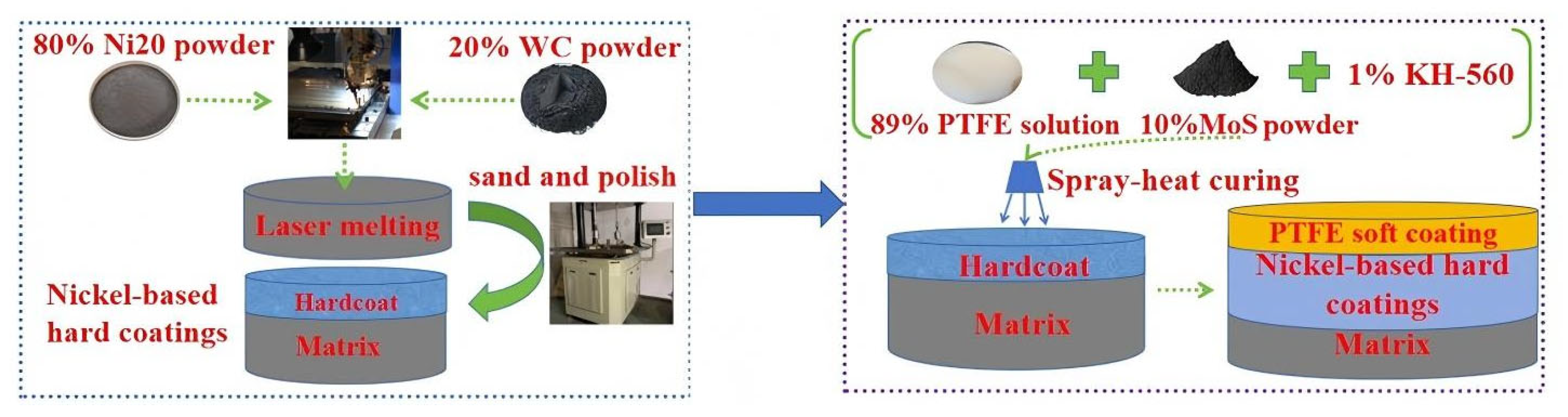
2.1. Sample Preparation

The preparation of nickel-based hard-soft composite coating includes the preparation of nickel-based hard coating and PTFE soft coating, in which the selection of preparation materials, proportions, and the determination of preparation processes are very important for the forming quality of coating [20]. The main components of 20CrMo bearing steel materials (abbreviated as M) is shown in Table 1, which mainly includes Cr (0.80~1.10 wt%), Mo (0.40~0.70 wt%), C (0.17~0.23 wt%), Si (0.17~0.37 wt%), Mn (0.15~0.25 wt%), and Fe (balance).
Figure 1 depicts the flow chart for the preparation of nickel-based hard-soft composite coating (abbreviated as SHC). The preparation process is as follows: First, the surface of 20CrMo is polished smooth using sandpaper, observe the 20CrMo with a metallographic microscope, polish it without obvious scratches until the surface is smooth without grinding marks, and the surface roughness reaches 0.2 μm before the layer is deposited. followed by cleaning using anhydrous ethanol to remove surface oxidized debris, avoiding defects such as oil contamination, porosity, and impurity particles on the surface of 20CrMo [21], and increasing the fusion-coating absorption rate. Second, choosing self-fusing nickel-based powders and tungsten carbide powders as cladding powders. The laser cladding powder used in this article is Ni20 alloy powder produced by Kennametal-Stellite, it particle size of 14~45 μm, and Ni20 powder contains elemental ratios as shown in Table 2. The particle size of tungsten carbide powder is 15~45 μm, the chemical composition is mainly composed of refractory metal tungsten and non-metallic carbon, and contains a small amount of Co, Cr, Mn, Ni, Mo, O and other impurity elements. Ni20 and WC powders are selected according to the mass ratio of 8:2, mechanically stirred, and dried in vacuum to remove moisture and prevent deterioration. Finally, the mixed powders are used to prepare nickel-based hard coating by laser cladding process. The laser cladding equipment adopts RFL-C6000 X-type high-power high-speed laser cladding machine. In the cladding process, synchronous powder feeding is adopted, the output power of laser cladding is 3500 W, the linear speed is 2 m/min, the step distance is 0.8, the powder feeding capacity is 25 g/min, the cladding head is 15 mm away from the substrate, the powder feeding air pressure (N2) is 0.3 MPa, the carrier gas flow is 600 L/h, the protective air pressure (N2) is 0.1 MPa, and the temperature is room temperature. The nickel-based hard coating (abbreviated as NC) prepared by the above operations is shown in Figure 2a, and the surface of the coating is in good molding condition with no obvious cracks generated. As shown in Figure 2b, in order to detect whether there are cracks and porosity inside NC, the surface non-destructive coloring flaw detection method is used to detect the flaw, and the results show that there are no cracks and porosity inside NC.
On the basis of NC, SHC is prepared. Firstly, the PTFE composite solution is configured: the PTFE emulsion, MoS2 powder, and KH-560 binder are mixed, then stir them with a magnetic stirrer, the ratio is shown in Table 3. Stirring at 600 rpm/min for 30 min to make the components evenly dispersed. Subsequently, The surface of NC is sandblasted to increase it roughness, and ensure the bonding between NC and the PTFE composite solution. The specimen is placed in ultrasonic cleaning agent for ultrasonic-assisted cleaning to remove oil and impurities on the surface, and dry it. The PTFE soft coating is prepared on the NC surface by spraying method. The spraying pressure is 0.25 MPa, the nozzle is 20 cm away from the sample, and the coating thickness is controlled at 20~30 μm. Then put the sprayed sample into the 80 °C drying oven to dry for 20 min. Finally, it is placed in a muffle furnace at a constant temperature of 370 °C for 20 min to obtain SHC, as shown in Figure 2c.
In order to test the bonding of PTFE soft coating with NC in SHC, the SHC is scratched by using a Baguette adhesion tester, and the test results are shown in Figure 2d. As shown in Table 4, according to the ISO comparative standard [22], the bonding properties are from strong to weak, corresponding to the grades from 0 to 5, and the ISO grades of SHC bonding properties are from 0 to 1, which are high and meet the experimental requirements.

2.2. Friction and Wear Experiment

In this paper, three kinds of specimens, M, NC and SHC, are used as research objects to carry out the friction and wear experiments under different loads and speeds. The friction and wear properties of the materials were tested using an HT-1000 ball-on-disc contact-rotation reciprocating high-temperature friction and wear tester (Lanzhou Zhongke Kaihua Technology Development Co., Ltd. Lanzhou, China). Depending on the application conditions of the friction components, there may be different friction counterparts. Therefore, the counterpart with high strength should be selected (Si3N4 ball have high strength), which can more truly reflect the friction and wear performance of the prepared composite material. So choosing Si3N4 ceramic ball as the counter material with a diameter of 6 mm. According to the Hertzian surface contact theory [23], the contact stress is calculated from Equations (1) and (2).
q = 6 F π 3 R 3 E * 2 1 3
E = 1 μ 1 2 E 1 + 1 μ 2 2 E 2
In the above equation, F-loading force (N); q-loading stress (MPa); R-radius of the grinding ball (mm); E1, E2-material elastic modulus; μ1, μ2-the Poisson’s ratio of the material.
As shown in Table 5, based on the Hertzian contact stress calculation, the stresses between the tribopairs are calculated to be 600 MPa, 750 MPa, 909.09 MPa,1000 MPa at 3 N, 6 N, 10 N, 15 N, respectively, which is below the yield stress of coating material and satisfies the contact stress requirement for the friction test. The test condition and temperature are dry friction and room temperature, the test time is 30 min, and the friction coefficient is automatically recorded by the force sensor. Using a FA2004E precision electronic scale to weigh the wear amount of the specimen before and after wear. According to the possible operating conditions of the mechanical parts, the slip speed is selected as 0.1 m/s, 0.3 m/s, 0.5 m/s, and 0.7 m/s.

2.3. Testing and Characterization

Using Vickers hardness tester to test the hardness value of the matrix and coating, five points are randomly selected for testing, applying pressure 0.2 kg, indentation time 10 s, the average value is taken. In order to characterize the phase composition of the coating, X-ray diffraction (XRD) (X’Pert PRO MPD, PANalytical B.V., Almelo, Netherlands) is used to detect the surface of the coating [24], the scanning speed is set to 5°/min, the scanning range is 10~90°, and the phase composition is analyzed according to the XRD data. Using scanning electron microscopy (SEM) (Hitachi Regulus8100, Hitachi High-Tech Corporation, Tokyo, Japan) and energy spectrometry (EDS) to investigate the micro-morphological organization and elemental distribution of the coating cross-section, and to investigate the surface wear mechanism of SHC. Using photoelectron spectroscopy (XPS) (PHI5000 VersaprobeIII XPS, ULVCA-PHI Inc, Chigasaki, Japan) to analyze the composition of the lubricating layer on the surface of SHC. Finally, the microscopic morphology of coating wear scars are characterized and analyzed by scanning electron microscope (SEM), the purpose is to study the formation mechanism of lubrication layer and wear reduction mechanism of SHC.

3. Results and Discussion

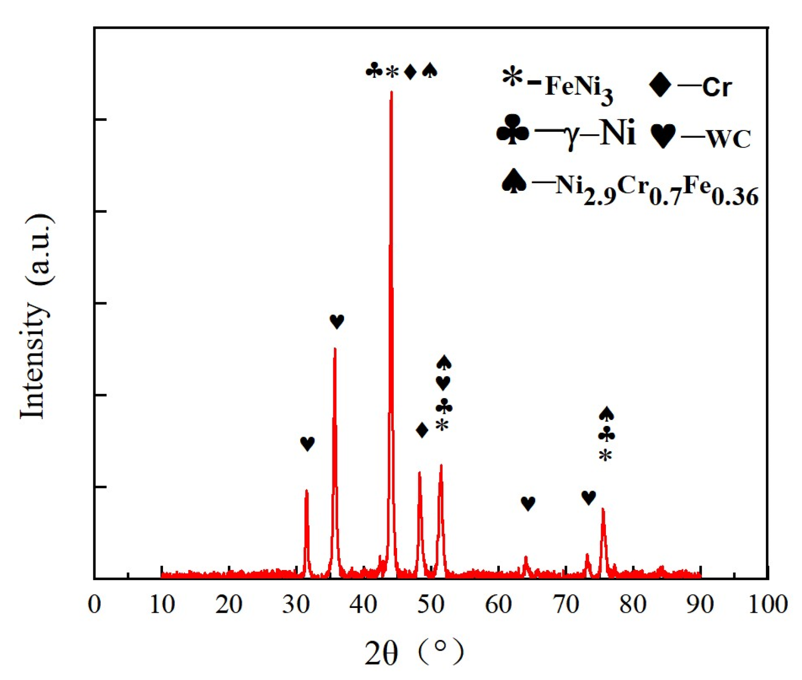
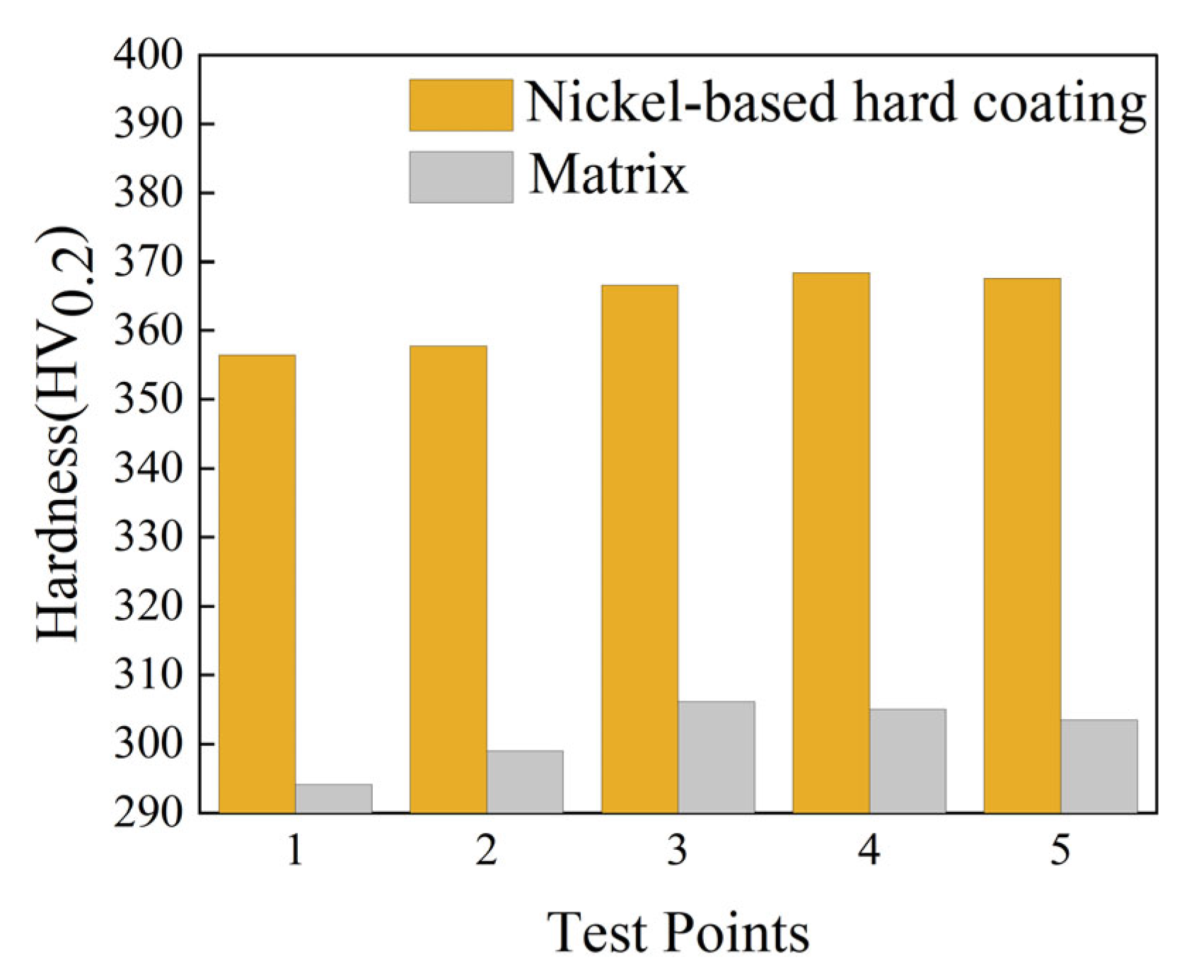
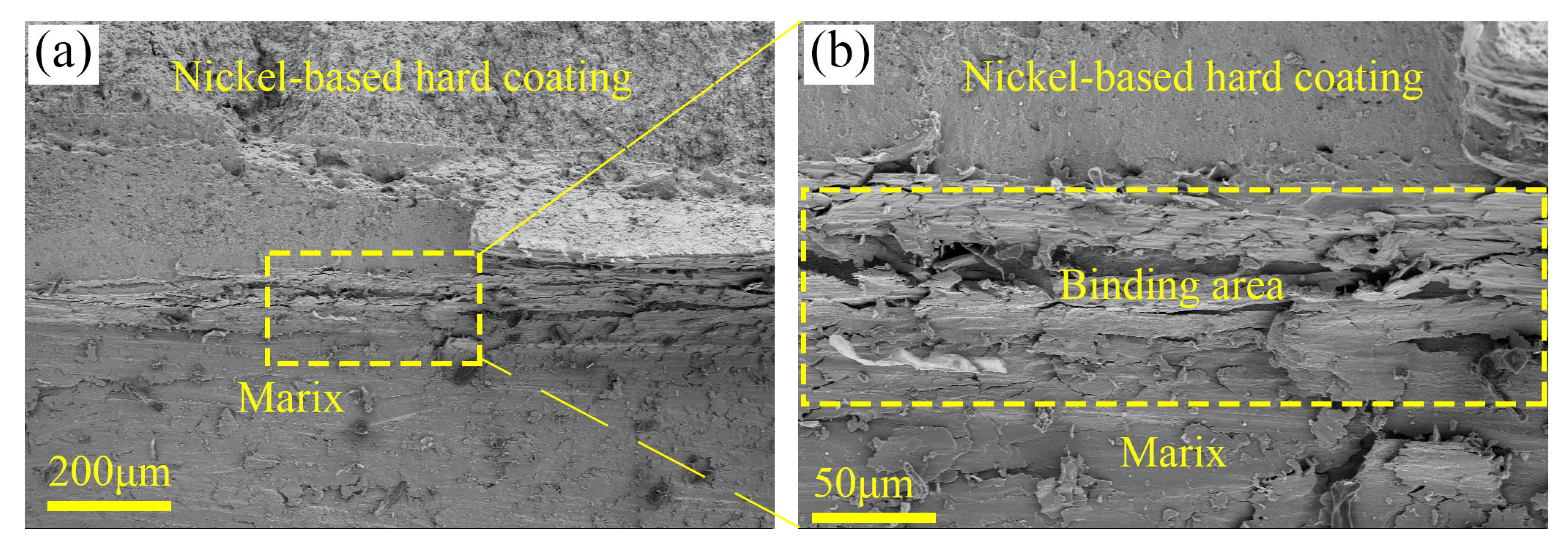
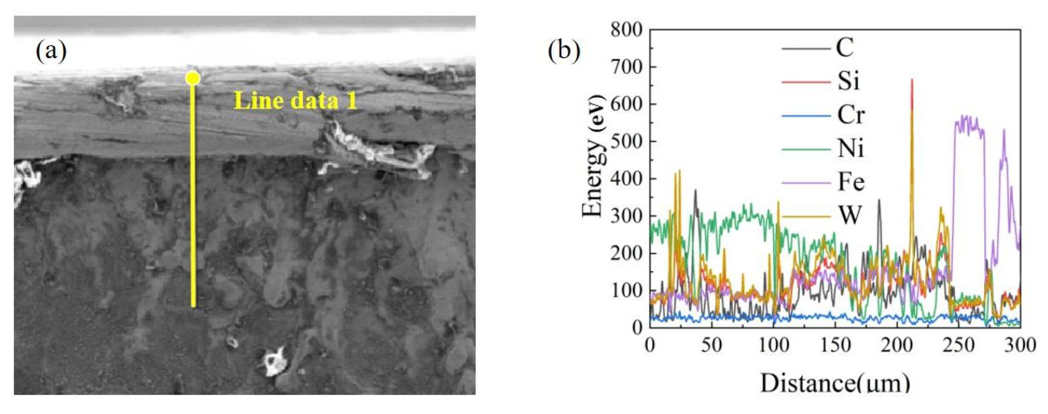
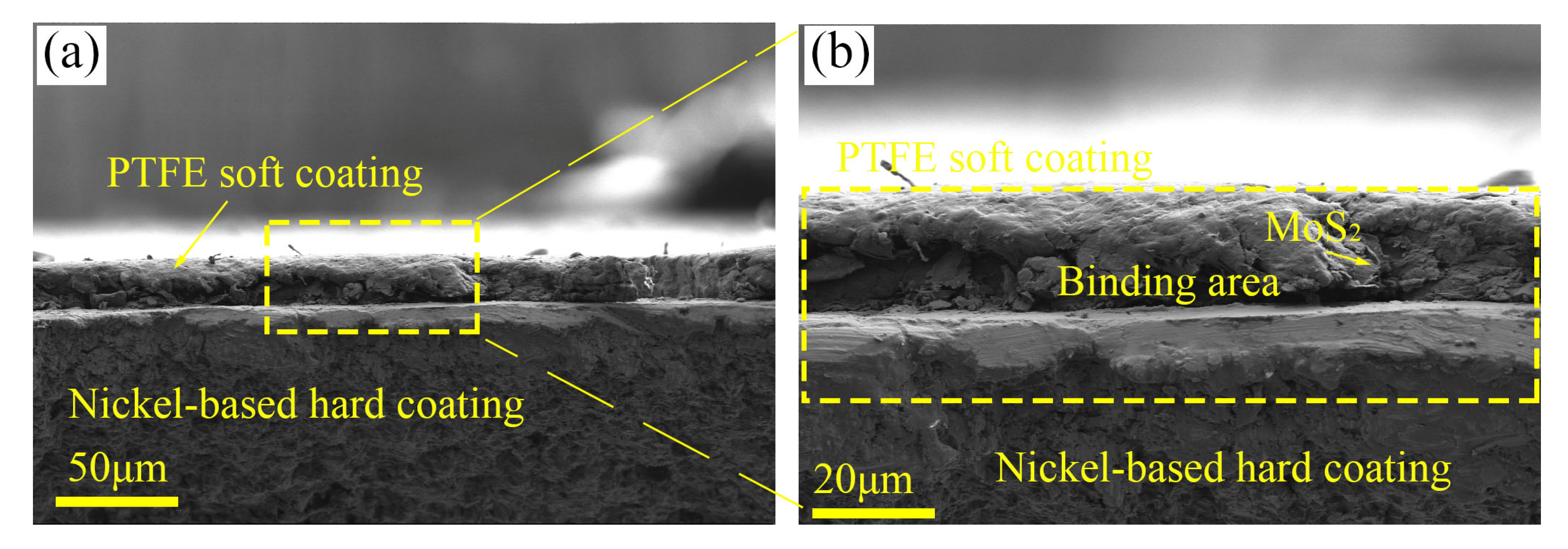
3.1. Coating Phase and Microstructure

In the laser cladding process, the high-energy laser beam acts between the powder and the matrix, and a series of physicochemical reactions will occur in the molten pool. In order to analyze the phase composition of the coating, according to XRD data, data processing is performed using software such as jade 6.5 and origin 2024. As shown in Figure 3, the main diffraction peak of the coating is γ-Ni solid melt, so the cladding layer uses γ-Ni solid melt as the matrix phase. Due to the low scanning speed, the melt pool gets more energy per unit time, resulting in more melt time in the melt pool, which leads to strong chemical reaction, more uniform melt composition, promoting the rate of elemental diffusion, and also promoting the formation of Ni-Cr-Fe phase, enhancing the bonding of the coating with the matrix. In addition, complex compounds such as FeNi3, Ni2.9Cr0.7Fe0.36 are also formed in the coating, which improve the hardness and wear resistance of the coating.
Vickers hardness tester is used to test the hardness of SHC. Since SHC is prepared on the surface of NC with a layer of 20~30 μm PTFE soft coating. The soft PTFE coating on the surface of SHC is not significant for hardness enhancement [25], so SHC and NC hardness are similar, only test NC surface hardness. As shown in Figure 4, Data shows that the surface hardness of M is basically maintained at about 300 HV0.2. The surface hardness of NC is increased to 360 HV0.2, which is about 20% higher than M. This is because WC base anti-wear material is added in the NC, which is conducive to enhancing the wear resistance of the material.
The cross-sectional microstructure of the prepared NC is observed using SEM, as shown in Figure 5a,b. NC is cladding on the surface of M, and there are microscopic pores within NC, which is because Ni20 and WC powder combine in the molten pool and produce gas. Due to the fast heating and cooling rates of laser cladding, the internal gas can not be discharged, and finally microscopic pores are formed. When the number and characteristics of microscopic pores are within a reasonable range, microscopic pores may play a role in storing abrasive debris and effectively reduce the wear amount of the coating. The high rate of temperature rise leads to a narrow transition zone between the coating and the matrix, a thin bonding line, and a good metallurgical bond between the coating and matrix is formed.
So as to explore the microstructure characteristics of NC, EDS is used to perform line scanning of the cross-section of the coating to explore the distribution of C, Si, Cr, Ni, Fe, W and other elements. Figure 6a,b show the EDS line scan cross-sectional images of NC. The results show that C, Cr, and W elements are evenly distributed from the top to the bottom of the coating, and as we approach the matrix, the content of Ni element decreases and the content of Fe element increases. This indicates that the Ni element mainly exists in the interior of the coating. The change of W element content is not obvious, which indicates that the coating is in a good state of fusion, and the elements are dispersed uniformly. Fe element mainly exists inside the matrix. The spectrum shows that the Fe element content increases gradually, indicating that the fusion efficiency is high, and a part of the matrix is melted and bonded with the coating, the bonding between the coating and the matrix is enhanced.
Cross-section specimen of SHC is prepared. The microscopic organization inside the coating was observed using SEM as shown in Figure 7a,b. The PTFE soft coating is cured on the surface of NC, with uniformly distributed layered MoS2 within the PTFE soft coating. Inside NC, micro-pores are present, forming a junction between the two coatings. The internal structure is distinct and well-formed, and meeting the experimental requirements.

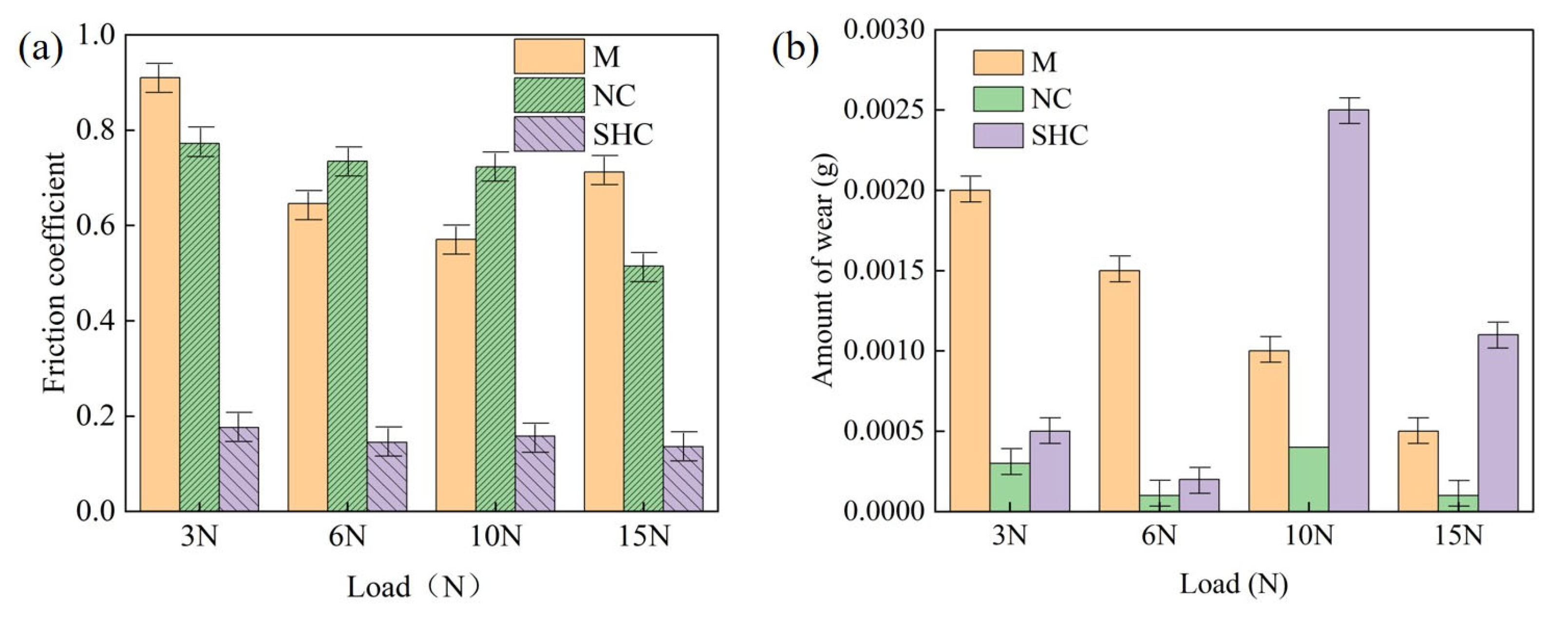
3.2. Friction Coefficient and Wear Amount Change Law

Friction and wear experiment is an important research tool to investigate the tribological properties of NC and SHC. This paper takes M, NC and SHC as the research object, and focuses on the study of the friction wear performance of three materials under different loads (3 N, 6 N, 10 N, 15 N) and speeds (0.1 m/s, 0.3 m/s, 0.5 m/s, 0.7 m/s).
Firstly, the friction and wear properties of M, NC and SHC at constant speed (0.3 m/s) and under different loads (3, 6, 10 and 15 N) are studied. As can be seen from the Figure 8a, the friction coefficient of M is higher than NC and SHC at 3 and 15 N, and slightly lower than NC at 6 N and 10 N. SHC friction coefficient remains low at around 0.15 throughout the loading conditions, and reaches a minimum of 0.14 at 15 N load, which is 80% and 70% lower than M and NC, respectively. This may be due to the fact that NC hardness is much higher than M, and at 3 N, the NC hardness is larger, and the surface is not easy to be worn down, resulting in a large friction coefficient. M has low surface hardness, but large surface roughness, which is easy to wear under low load and produce a large amount of abrasive debris, which makes the friction coefficient large. Under 6 N and 10 N conditions, the NC surface may be worn down and produce hard abrasive debris, resulting in a slightly higher friction coefficient than M.
The wear amount can be determined by weighing the difference in the quality of the specimens before and after wear, and the wear amount of each specimen is shown in Figure 8b. The wear amount of M decreases with increasing load, but it is much higher than NC and SHC at 3 N (0.002 g) and 6 N (0.0015 g). The wear amount of NC is not change much under the load conditions of 3~15 N, and basically remains at about 0.0005 g. The wear amount of SHC decreases and then increases with the increase of load, and remains around 0.0005 g at loads of 3–6 N. When the load is increased to 10 N, the wear amount increases to a maximum value of 0.0025 g, while at 15 N, decreases to 0.0011 g. This is due to the fact that the surface hardness of M is lower than NC and SHC, the wear resistance is poor and the surface is prone to worn, whereas NC and SHC are characterized by high hardness, high load bearing capacity and excellent wear resistance. The wear amount of SHC (0.0002 g) is 87% lower than M, which is slightly higher compared to NC at 6 N. This is because PTFE is softer and tends to wear through under low load conditions, resulting in slightly more wear amount than NC.
Secondly, the friction and wear properties of each specimen (M, NC, SHC) are investigated under constant load (6 N) and different speeds (0.1 m/s, 0.3 m/s, 0.5 m/s, 0.7 m/s) conditions. As can be seen from the Figure 9a, the friction coefficient of M is also higher than that of NC and SHC at 0.1 m/s and 0.3 m/s, and is not much different from the NC at 0.5 m/s. The friction coefficient of M is reduced at 0.7 m/s, which is slightly lower than NC. During the whole friction process, the friction coefficient of SHC is still in the lowest state, which is stable at about 0.15. This is due to the synergy between PTFE and MoS2, whose low shear properties give the coating excellent tribological properties and are also suitable for a wide range of speed applications.
The wear amount can be derived by weighing the difference in mass of the specimens before and after wear, as shown in Figure 9b for each specimen at different speed conditions. The wear amount of M is much higher than NC and SHC under the whole friction speed conditions, and M has low strength and easy surface to be worn. The wear amount of NC does not change much under the conditions of 0.1 m/s–0.5 m/s, and basically remains at about 0.0002 g, which is attributed to the excellent wear resistance of NC. SHC exhibits the lowest wear amount at 0.5 m/s, the wear amount of SHC (0.0002 g) is much smaller than M (0.0009 g), with a 78% reduction compared to M, and a slightly larger wear amount in comparison to NC (0.0001 g). This is due to the synergistic effect of PTFE on the surface of the SHC and the internal MoS2, which effectively enhances the friction reduction performance of the coating surface, and gradually forms a stable lubricating layer during the friction process. NC provides support for the whole friction process, so that the wear amount of the material is stably maintained in a very low range.

3.3. Lubrication Layer Formation and Friction and Wear Mechanism

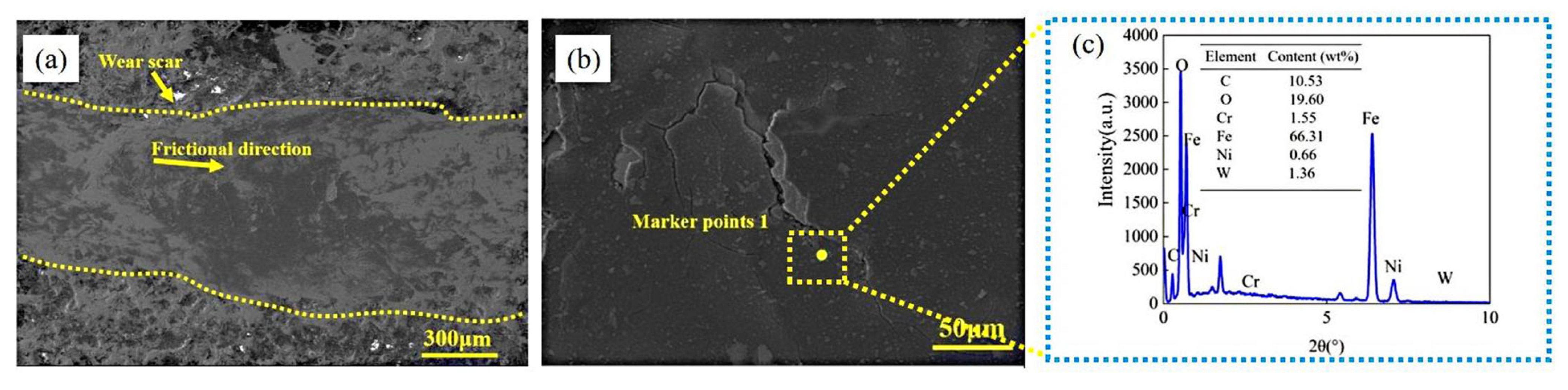
3.3.1. Worn Surface Microscopic Morphology of M and NC

The optimal speed condition of M and NC are used as a comparative study, and the micro-morphology of the worn surface is scanned by SEM, which is combined with EDS energy spectroscopy to investigate the distribution of elements on the worn surface as well as the wear mechanism. Figure 10a is micro-morphology of the worn surface of M under optimal condition (0.7 m/s, 6 N). The worn surface forms a flatter and continuous wear scar with a large width of the wear scar, which is due to the lower surface strength of M, it is prone to deformation during friction, and it is also the main factor for the lower coefficient of friction and wear amount. The worn surface is characterized by cracks and micro-pits, and it deformation is more severe. Combined with the EDS elemental analysis on worn surface of M in Figure 10c, it can be seen that Fe content reaches 66.31 wt%, and the O elemental content is 19.6 wt%, which indicates that an oxidation reaction occurs on the worn surface of M, and the generated oxides play a lubricating role [26], so that the main wear mechanism of M surface under this working condition is plastic deformation [27,28] and oxidative wear [29,30].
The micro-morphology of the worn surface of NC under optimal condition (0.3 m/s, 6 N) is shown in Figure 11a. The wear scar is narrow and discontinuous, there is a small number of plow grooves and a slight abrasive grain shedding phenomenon on the worn surface, and the internal micropores are visible. Due to the high surface hardness of NC, the friction coefficient is relatively large, but the degree of wear is lighter compared to the M and the wear amount is smaller. As shown in Figure 11c, the analysis of the EDS elements on worn surface of NC shows that a large amount of W and Ni elements are present on the worn surface and small amount of O elements, which suggests that the main wear mechanisms on NC surface are abrasive wear [31] and slight oxidative wear.

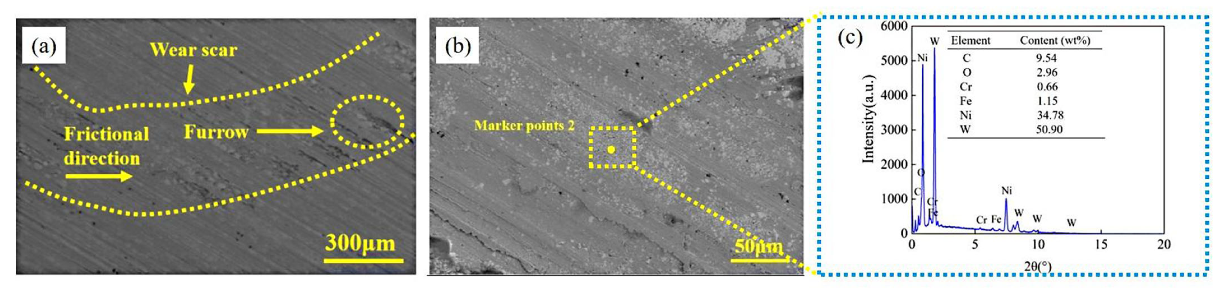
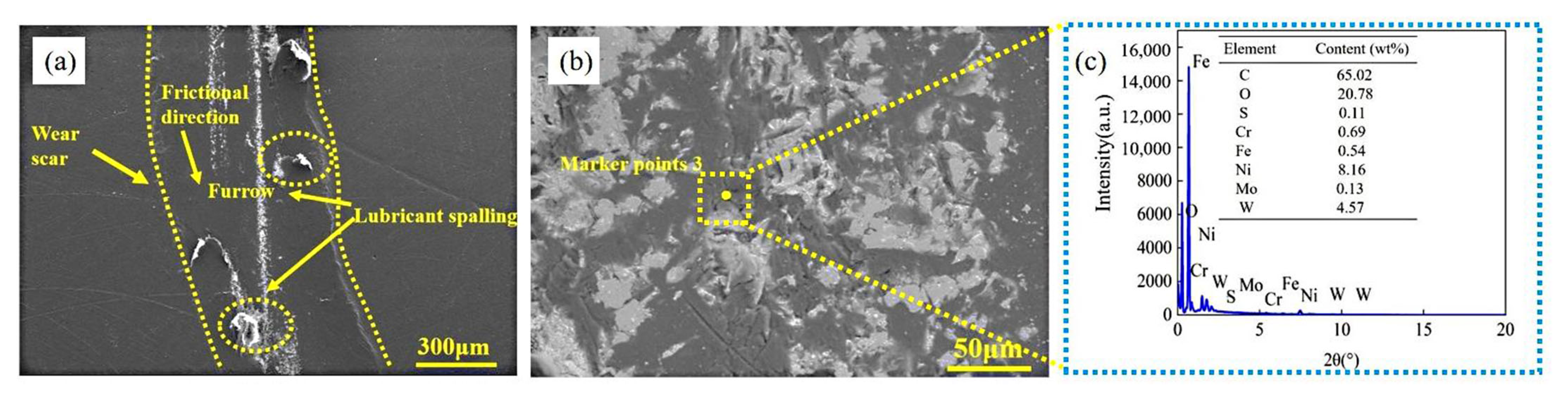
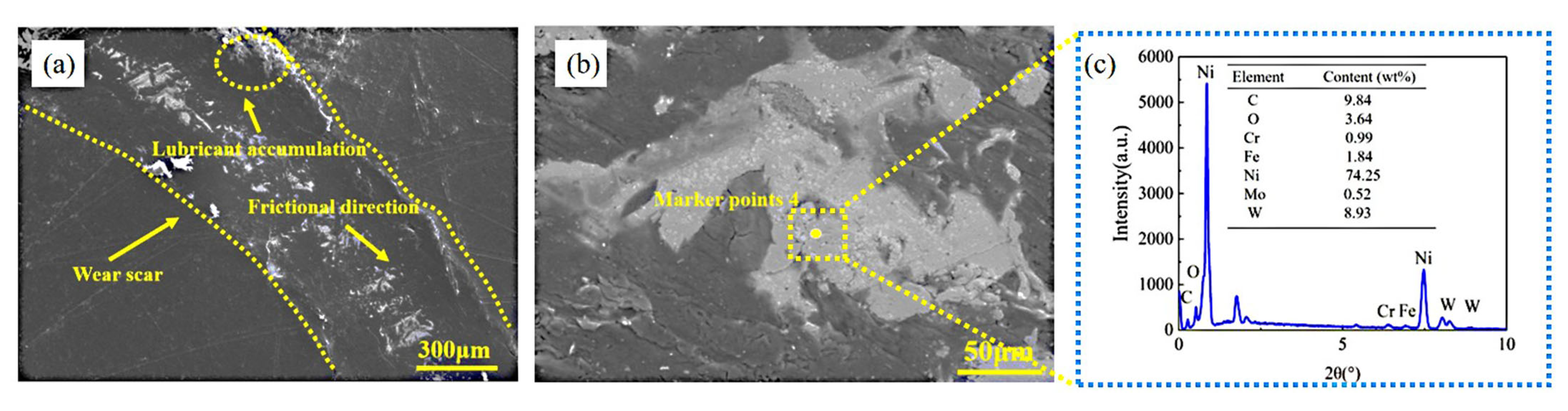
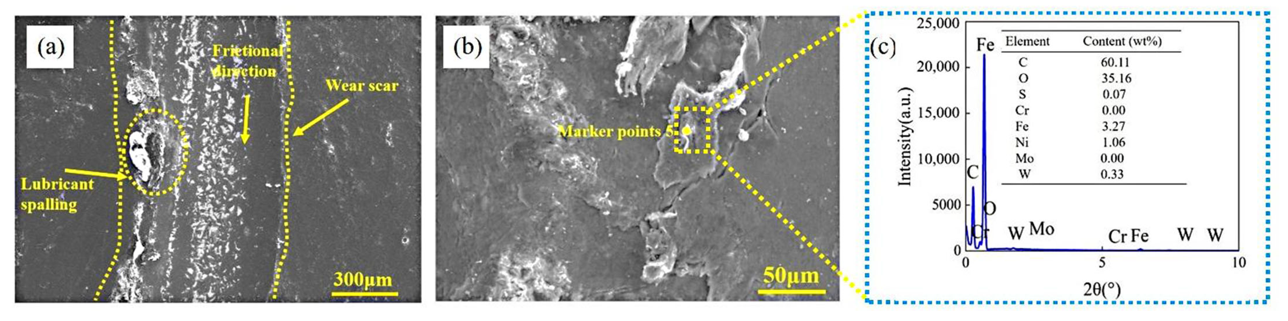
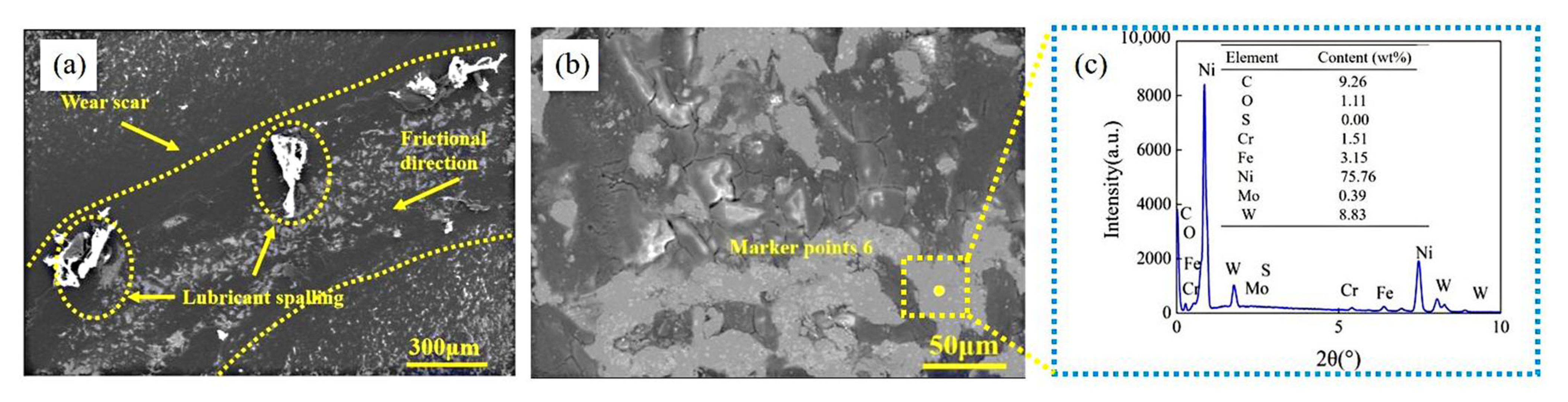
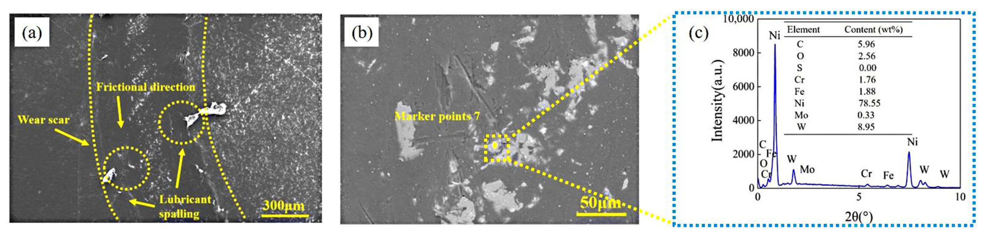
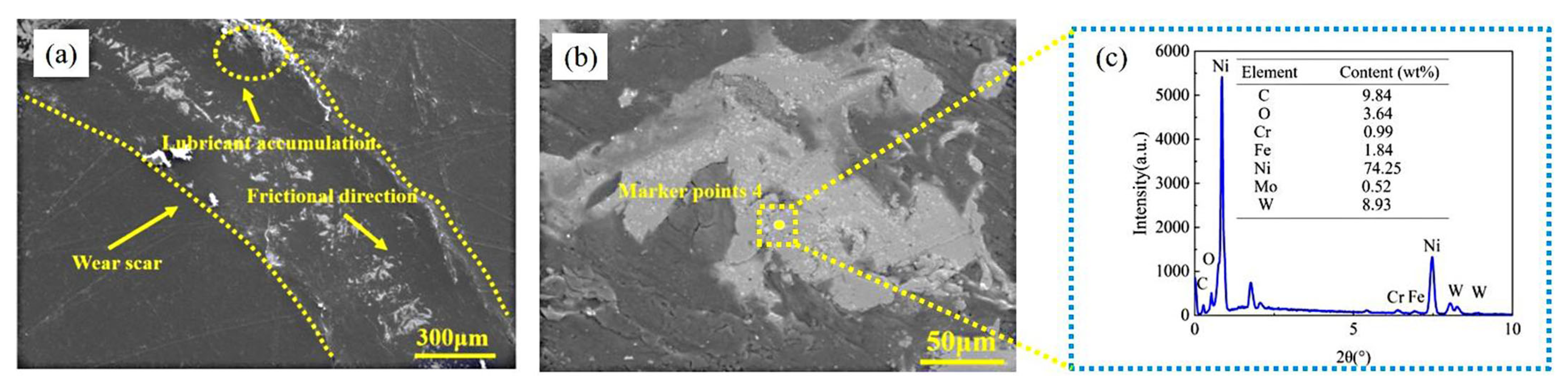
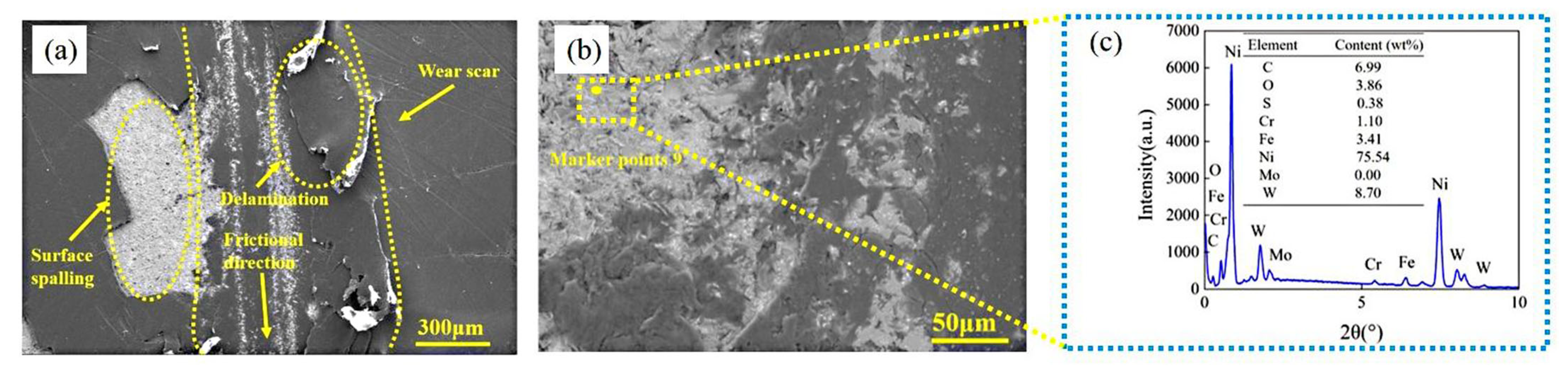
3.3.2. Mechanism of Composite Lubrication Layer Formation on Worn Surface of SHC at Different Loads

Figure 12a shows morphology of the worn surface of SHC at 3 N. There is less accumulation of PTFE composite lubricant at the edge of the wear scar, and slight spalling on the surface, the wear scar is discontinuous. The worn surface has slight furrows and other features, the worn surface area is not concentrated, the wear area is small, and the worn surface does not form a stable composite lubricant layer. As shown in Figure 12c analyzing the EDS elements of the worn surface, it can be seen that it mainly contains C and O elements, the density of the worn surface area is high, but the degree of wear is light, and the surface Ni and O elements are more, so the wear mechanism of SHC under this condition is dominated by slight plastic deformation as well as oxidative wear.
The micro-morphology of the worn surface of SHC at 6 N is shown in Figure 13a. The lubricant accumulation on the edge of the wear scar on the surface of the coating is intensified, the wear scar is obvious, but the surface spalling characteristics are not obvious. The wear scar is continuous and the density is increased, and a stable composite lubrication layer is formed under this condition. Combined with EDS elemental analysis of SHC under 6 N condition in Figure 13c, it mainly contains C, O and Ni elements, in which the content of Ni element reaches 29.54 wt%, and the main Ni element comes from NC, which proves that the surface PTFE soft coating is slightly abraded under this condition, and the surface PTFE is dragged. The content of O element on the worn surface is 7.89 wt%, so that the worn surface still undergoes slight oxidization reaction. Under this condition, the main wear mechanism of SHC includes abrasive wear, adhesive wear [32], and oxidative wear.
The micro-morphology of the worn surface of SHC at 10 N is shown in Figure 14a, the edge of the wear scar appears to be a large composite abrasive chip shedding accumulation characteristics, although the wear to form a composite lubrication layer, the width of the wear scar is increased, and the wear scar internal shedding is serious. The overall wear scar shows a long plow furrow shape, the composite lubrication layer is destroyed resulting in increased wear, and the SHC wear amount is the largest under this condition. Combined with the EDS elemental analysis on worn surface of SHC under 10 N in Figure 14c, it can be seen that the O elemental content on the worn surface under this condition reaches 35.16 wt%, and serious oxidation reaction occurs. There are PTFE composite abrasive tissue adhesion and accumulation at the edge of the wear scar, and the wear mechanism of SHC in this condition is severe oxidative wear as well as adhesive wear.
As shown in Figure 15a, When the load is increased to 15 N, the width of the wear scar decreases, the volume of wear scar edge shedding decreases, and the density of abrasion chips shedding at the bottom of the wear scar slightly decreases. The surface composite abrasion chips are repeatedly milled and shaped, the composite lubrication layer is obvious, and the wear amount decreases. Combined with the EDS elemental analysis on worn surface of SHC under 15 N condition, as shown in Figure 15c, the density of the wear scar increases, and the content of Ni and W elements on the surface are 75 wt% and 8.83 wt%, respectively. It proves that the wear scar is a mixture of nickel-based hard-soft composite coating with wear debris, and the lubricating layer on the surface is worn through to produce a larger number of cracks. Therefore, the main wear mechanism under this condition is plastic deformation, adhesive wear, and severe abrasive wear.
Under the whole loading condition, with the increase of load, the width of wear scar shows a tendency of increasing and then decreasing. Under low load conditions (3 N, 6 N), the accumulation of PTFE composite lubricant on the edge of the coating wear scars is not obvious, the wear scars are narrower, and there is less adhesion of the wear debris on the surface. In medium load condition (10 N), the width of the wear scar continues to increase, the wear amount is the largest, the volume of dislodged the wear debris eincreases, and this condition had the greatest effect on the coating. At heavy load condition (15 N), the width of the wear scar decreases and the volume of the surface wear debris decreases, but the abrasive chip adhesion characteristics increase, which is also consistent with the phenomenon of decreasing wear amount. Combined with the wear morphology of SHC under the whole loading conditions, it can be seen that the wear scar density of SHC on the surface shows an increasing trend, with obvious lubrication layer characteristic, and has excellent tribological performance under 6 N condition. At 10 N load, the edge accumulation is the most serious, there is agglomeration phenomenon. The lubrication layer is worn through, adhesion, detachment, the composite lubrication layer is damaged, and the wear amount is the largest. Under 15 N condition, the composite lubrication layer edge accumulation is reduced, the lubrication of the abrasive debris is repeatedly crushed to form a more stable composite lubrication layer, which has the effect of reducing the wear amount, and the wear amount is subsequently reduced. Due to the low shear performance of the surface PTFE, the surface composite lubrication layer mainly occurs in the accumulation, adhesion, a small portion of the shedding away, only in the 10 N condition shedding serious. SHC is adapted to a wide range of loading conditions, and the tribological performance is significantly improved compared to M and NC.

3.3.3. Mechanism of Composite Lubrication Layer Formation on Worn Surfaces of SHC Under Different Speeds

As shown in Figure 16a, the micro-morphology of the worn surface of SHC at 0.1 m/s, the wear scar is narrower under this condition, and there is slight flaking on the surface, discontinuity of the wear scar and slight furrowing characteristics. There is less accumulation on the edge of the wear scar, and no stable lubrication layer formed on the surface. Combined with the EDS elemental analysis on the worn surface of SHC at 0.1 m/s in Figure 16c, it mainly contains Ni and W elements, which shows that the surface PTFE soft coating is abraded, and NC abrasive debris exists on the surface, so under this condition, the SHC is mainly subjected to slight abrasive wear as well as slight adhesive and oxidative wear as the main wear mechanism.
Figure 17a shows the micro-morphology of the worn surface of SHC at 0.3 m/s. The lubricant accumulation on the edge of the coating worn surface is intensified, the wear scar is obvious, but the surface spalling characteristic is not obvious. The wear scar is continuous and the density increases, and a stable composite lubrication layer is formed under this condition. Combined with the EDS elemental analysis on the worn surface of SHC under 0.3 m/s condition, as shown in Figure 17c, the worn surface mainly contains C, O and Ni elements, in which the content of Ni element reaches 29.54 wt%, and the main source of Ni element is from NC. It proves that the surface PTFE soft coating is slightly abraded under this condition. The surface PTFE is dragged, and the content of O element on the worn surface is 7.89 wt%, so that the worn surface still undergoes slight oxidization reaction. Under this condition, the main wear mechanism of SHC includes abrasive wear, adhesion wear, and oxidative wear.
In order to visualize the elemental distribution state of the surface composite lubrication layer, the surface composite lubrication layer is scanned under 0.3 m/s speed condition, as shown in Figure 18b–h. The distribution state of C, O, S, Cr, Fe, Ni, Mo, and W elements is mainly observed. As can be seen that the main elements of the lubrication layer are Ni, Fe, W elements. In the friction process, the surface layer of PTFE is abraded, NC is worn, hard coating abrasive particles and PTFE soft abrasive debris are mixed and subjected to milling to form a composite lubrication layer. The O element on the surface of the lubrication layer is more uniformly distributed, a slight oxidation reaction occurs, and the resulting oxide is uniformly dispersed on the worn surface, contributing to the enhancement the tribological properties of the coating surface.
When the speed is increased to 0.5 m/s, the micro-morphology of the worn surface is shown in Figure 19a. The flaky PTFE shedding and sticking phenomenon occurs at the edge of the wear scar, the edge buildup is serious, and the abrasion density at the bottom of the wear scar increases, but the surface of the coating is intact, and a stable lubrication layer exists. Combined with the EDS elemental analysis on worn surface of the SHC under 0.5 m/s in Figure 19c, the Ni elemental content of the worn surface under this condition reaches 64.74 wt%, which is similar to 0.3 m/s, and it still contains a higher content of W element. It indicated that the worn surface is mainly a mixture of NC the wear debris and PTFE coating tissue, so the wear mechanism of SHC under this condition is severe abrasive wear, adhesive wear and plastic deformation.
Figure 20a. shows the micro-morphology of the worn surface of SHC at 0.7 m/s. The width of the wear scar is reduced. However, there is a large amount of PTFE lubricant shedding phenomenon at the edge of the wear scar, and a large number of furrows and laminar PTFE tissues are shedding and sticking on the surface, accompanied by a serious detachment of PTFE coating, which is in line with the phenomenon of large wear amount. Analyzing the EDS elements on the worn surface of the SHC under 0.7 m/s condition in Figure 20c, the Ni element content on the surface continues to increase, the density of the wear scar increases, a large area of PTFE coating flaking features, the surface lubrication layer is worn, and a larger number of cracks are produced [33]. There is also 3.86 wt% of elemental O present on the worn surface, so the main wear mechanism of SHC under this condition are plastic deformation, adhesive wear, slight oxidative wear, and severe abrasive wear.
Throughout the speed conditions, The SHC shows a tendency to increase and then decrease the width of the wear scars along with the increase of the friction speed. At low speed condition (0.1 m/s, 0.3 m/s), the width of the wear scars are small, the surface abrasive debris are small, the abrasion density are small and discontinuous. No PTFE composite lubricant flaking on the surface at 0.1 m/s, with the increase of speed, a small amount of PTFE composite lubricant buildup appears on the edge of the coating wear scar at 0.3 m/s, but the wear amount of coating is small. At medium speed (0.5 m/s) condition, the width of the wear scar increases and the edge of the accumulation is serious, there is PTFE coating organization adhesion characteristics, and abrasion density increases, However, the organization of the composite lubricant is mainly based on adhesion and accumulation, and the composite lubrication layer is formed by repeated crushing, so the wear amount does not change much compared to the low speed conditions [34]. In the high speed (0.7 m/s) condition, the width of the wear scar is reduced, but the surface appears to be a large area of the phenomenon of shedding. The area of the wear scar continues to increase under this condition, with the presence of a long furrow feature, and the surface PTFE coating is carried away by adhesion, making the wear amount the largest at different speed conditions. Analyzing the topography of SHC surface wear scar under speed conditions, it can be seen that SHC wear scar under different speed conditions is more stable, mainly lubrication layer accumulation and adhesion phenomenon, abrasion density shows an increasing trend. However the spalling is not serious, which is also consistent with the phenomenon of a small and stable wear amount, so SHC is adapted to the low and medium working conditions, and is not adapted to the high speed working condition.
Combined with the morphology of SHC under variable load and speed, it can be seen that SHC has less influence under variable speed, with stable fluctuation in the width of wear scar, less edge buildup, and a smooth trend in the growth of the wear scar area. Controlled lubrication layer formation under multi-speed conditions and excellent tribological performance under low, medium and high operating conditions. SHC is greatly affected by the load, the lubrication layer is formed to adapt to a wide range of load conditions. Compared with M and NC, in low, medium and heavy load conditions, friction reduction and wear resistance performance of SHC is excellent.

3.4. Synergistic Friction Reduction and Wear Resistance Mechanism

3.4.1. Phase Analysis of Lubricating Layer of SHC

From the study of lubrication layer formation mechanism of SHC, it can be seen that in the friction process, the wear debris on the surface of SHC is subjected to milling to form a composite lubrication layer, which shows excellent friction-reducing and wear-resistant properties. Under the condition of 0.3 m/s, a stable composite lubrication layer is formed on the surface of SHC, which can effectively reduce the friction coefficient and wear amount. Based on the above research, the main components and compounds of the composite lubrication layer are explored, and the mechanism of synergistic friction reduction and wear resistance action between the surface layer and the subsurface layer is analyzed. The formation mechanism of surface layer and sub-surface layer and the friction reduction and wear resistance mechanism of SHC under variable speed conditions are investigated by advanced testing techniques.
According to the above study, the main components of the stable composite lubrication layer are C, O, Ni, Fe, W, Mo and other elements, but it is not clear what kind of compounds exist in each element, and what kind of physicochemical reaction occurs is not clear, which are closely related to the lubrication mechanism of the lubrication layer [35,36]. In order to analyze the phase composition of the coating, according to XPS data, data processing is performed using software such as Avantage 5.9, and the results are shown in Figure 21. The O1s peaks located at 531.0 eV, 532.0 eV, and 534.0 eV indicate a more severe oxidation reaction on the worn surface, with a large amount of oxide present. The Fe2p peaks at 710.4 eV as well as 710.5 eV indicate the presence of Fe and its oxides on the worn surface. The Ni2p peak at 853.8 eV indicates the presence of Ni element on the worn surface. The Ni2p peak at 853.8 eV indicates the presence of Ni on the worn surface. The W4f peaks at 33.5 eV, 35.2 eV, 35.8 eV, and 37.0 eV also indicate that elemental W is also oxidized on the worn surface, producing oxides such as WO2 and WO3. The Mo3d peaks located at 228.0 eV, 229.5 eV, 231.1 eV, 232.6 eV, 233.1 eV, and 238.9 eV indicate the generation of multiple molybdenum elemental compounds on the worn surfaces, which contain MoO2, MoO3 oxides. In summary, surface lubrication layer of SHC is mainly composed of a variety of elemental oxides and compounds, which enhances the friction reduction and wear resistance of the coating surface, while the overall strength of the coating surface is also significantly improved.

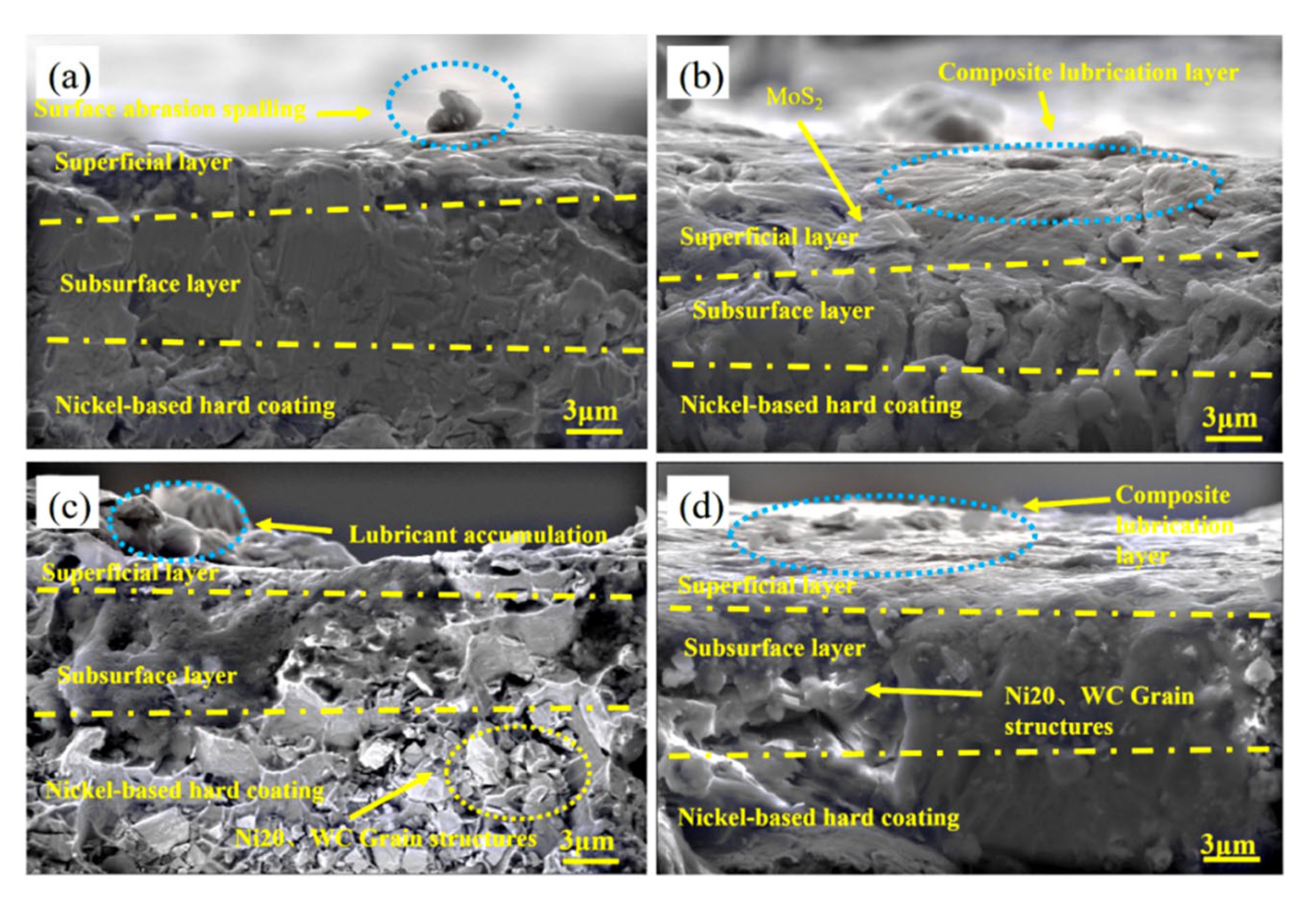
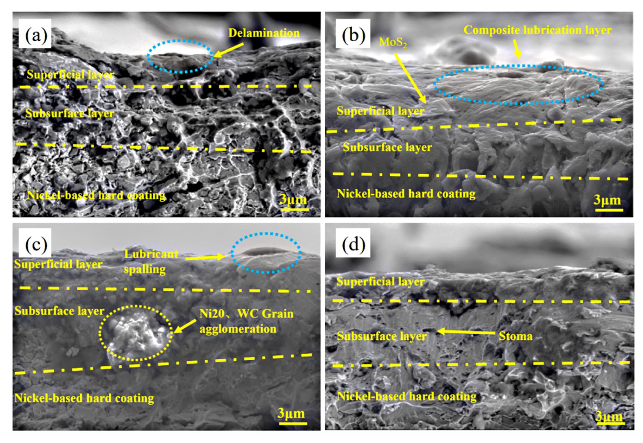
3.4.2. Microstructure Evolution of Surface and Subsurface Layers of SHC

Figure 22 shows the microstructure and morphology of the cross-sectional wear scar of SHC under variable load conditions. As shown in Figure 22a for the microstructure and morphology of the cross-sectional wear scar of SHC under 3 N load, due to the small load, the surface layer of PTFE lubricant buildup, shedding phenomenon is relatively light, the surface layer thickness is small and the deformation is not large. Surface layer under the organization of the grain refinement region for the subsurface layer, mainly from the friction process load, this region is not obvious deformation, not the formation of a stable composite lubrication layer, but the degree of wear is relatively light. Figure 22b shows the microstructure and morphology of the cross-sectional wear scar of SHC under 6 N load. There is a phenomenon of tissue refinement in the surface layer under this condition, a large number of PTFE and MoS2 tissues are attached to the sub-surface layer, and the thickness of the surface layer is increased to form a composite lubrication layer. The coating bonds well under these conditions, which is consistent with the low coefficient of friction and the wear amount. Figure 22c shows the microstructure and morphology of the cross-sectional wear scar of SHC under 10 N load, due to the increase of load, the composite lubricator of the coating surface layer is seriously accumulated, there is a serious spalling phenomenon, the wear scar is obvious, and the surface layer becomes thinner. The subsurface layer shows grain refinement and laminar fracture characteristics, and the composite lubrication layer is damaged, which is also consistent with the phenomenon of higher wear. Figure 22d shows the microstructure and morphology of the cross-sectional wear scar of SHC at 15 N. When the load continues to increase, the surface layer increases through the lapping density, and the tissue refinement characteristics intensify. Surface composite lubrication the wear debris is repeatedly crushed to form a composite lubrication layer again, the subsurface layer rupture is continuously compacted, the fracture phenomenon is reduced. The friction coefficient is the lowest in this condition, and the wear amount is reduced compared to 10 N.
To analyze the formation of composite lubrication layer in the surface layer of the coating and the evolution of the subsurface organization by combining the microstructure and morphology of the cross-sectional wear scars of SHC under the whole loading conditions. The results show that at low loads, the surface deformation of the composite coating is small, the subsurface layer is lightly extruded, and there is no grain refinement at 3 N, making it difficult to form a composite lubrication layer. With the load increase to 6 N appeared organization refinement characteristics, and the surface lubrication layer characteristics are obvious. The material has excellent wear reduction and wear resistance characteristics. When the load is increased to medium load, the surface layer deformation is serious, the thickness of the surface layer is reduced, the subsurface layer is extruded and deformed and fractured, the surface composite lubrication layer is damaged, and the wear is more serious. Under heavy load condition, the surface layer structure is refined again, the composite lubrication layer is formed again, and the degree of wear is reduced.
Figure 23 shows the microstructure morphology of the cross-sectional wear scars of SHC at different speeds. As shown in Figure 23a for the SHC 0.1 m/s speed under the wear scar microstructure morphology, although this time the friction speed is small, due to the fixed load of 6 N, the surface layer of lubricant buildup, layer shedding characteristics are obvious. The deformation is more serious, the subsurface layer extrusion deformation is large, and a stable composite lubricant layer is not formed. Figure 23b shows the microstructure and morphology of the cross-sectional wear scar of SHC at 0.3 m/s, Under this condition, the surface layer has tissue refinement phenomenon, the subsurface layer is attached with a large number of PTFE tissue and MoS2, the surface layer is thicker, forming a stable composite lubrication layer. The coating bonding is better under this condition, which is also consistent with the lower coefficient of friction and the phenomenon of the wear amount. Figure 23c shows the microstructure and morphology of the cross-sectional wear scar of SHC at 0.5 m/s, due to the increase of speed, the accumulation of composite lubrication on the surface layer of the coating is reduced, the surface is smooth, there is a slight peeling phenomenon, and the thickness of the surface layer is reduced. The subsurface layer is subjected to extrusion and deformation resulting in the reduction of fracture characteristics, the formation of a composite lubrication layer on the surface, and a lower degree of wear. Figure 23d shows the microstructure morphology of the cross-sectional wear scar of SHC at 0.7 m/s, when the speed continues to increase, the thickness of the surface layer decreases, and again tissue refinement characteristics. Surface composite lubrication abrasive debris again to form a stable composite lubrication layer by repeated crushing and then rupture, subsurface layer rupture refinement is continued compaction, and fracture phenomenon is aggravated. The composite coating wear is the most serious under this condition, with the largest wear amount.
Combined with the evolution of the microstructure and morphology of the cross-sectional wear scars of SHC under the whole speed conditions, The analysis results show that under low speeds condition, At 0.1 m/s, the surface deformation of the composite coating is large, the subsurface layer is severely extruded, there are grain refinement features, the surface layer exists layer shedding phenomenon, and it is not easy to form a composite lubrication layer. When the speed increases to 0.3 m/s, the surface layer organization is refined by extrusion, the subsurface layer deformation is not obvious, the surface layer forms a composite lubrication layer, and the material shows excellent wear reduction and wear resistance characteristics. At medium speed condition, the surface layer is smooth, but the thickness of the surface layer is reduced, the subsurface layer is deformed by extrusion and makes the fracture characteristics reduced. The surface is easy to form a composite lubrication layer, and the wear is lighter. When the speed increases to high speed, the surface layer thickness continues to decrease, the subsurface layer by extrusion grain refinement is obvious, the surface of the formed composite lubrication layer is destroyed, and the degree of wear is large.

3.4.3. Synergistic Friction and Wear Resistance Mechanism of SHC Surface Layer and Sub-Surface Layer

According to the above analysis, the wear evolution of lubrication layer of SHC under different conditions is shown in Figure 24. Figure 24a shows the structure diagram of SHC, the PTFE soft coating is located in the top layer of the structure, which synergizes well with the NC in the middle layer to form a soft-hard composite coating structure with the matrix.
Figure 24b shows the wear evolution of lubrication layer of SHC under low load/speed conditions, at this time. Due to the surface load and speed are small, on the worn surface, the wear scar is shallow, and it width is small, the phenomenon of lubrication phase accumulation at the edge of the wear scar is not obvious. The PTFE soft coating is not worn out, and the soft wear debris produced by friction have a good friction-reducing effect. Figure 24c shows the wear evolution of lubrication layer of SHC under medium load condition, with deepening of the depth of the wear scar on the worn surface, increasing of the wear scar width compared to the low load. The PTFE soft coating is worn through, with severe adhesion and detachment to the friction partner, increased buildup on the edge of the wear scar, and increased wear amount.
Figure 24d shows the lubrication layer wear evolution of SHC under medium speed condition. At medium speed, the PTFE/MoS2 lubricant coating on the surface is squeezed and ruptured during the friction process, and the wear debris is free between the friction partner and matrix, The wear debris is compacted and form a continuous and stable lubricant layer under a high load, thus obtaining a small and stable friction coefficient. At the same time, NC under the PTFE coating provides good support, and the WC in the coating enhances the surface hardness of the coating, which improves the wear resistance of the coating. Figure 24e shows the wear of lubrication layer of SHC under heavy load condition, the lubrication layer which was originally broken ring is repeatedly crushed, and the resulting wear debris forms the composite lubrication layer again. During the whole friction process, PTFE composite wear debris is free around the wear scar, while reducing the friction coefficient, wear amount of the coating is also improved. Through the soft and hard integrated structure, friction reduction and wear resistance is realized at the same time. Figure 24f shows the the lubrication layer wear evolution of SHC under high speed condition. At high speed condition, more than the critical friction speed of the composite lubrication layer, in the process of friction is squeezed, rupture, and the adhesion phenomenon occurs with the friction partner. There is a rupture as well as a large area of detachment characteristics, the lubrication layer is destroyed, and the degree of wear is larger. The nickel-based hard-soft composite coating structure has obvious characteristics of the lubrication layer under wide load and multi-speed conditions, realizing controllable friction behavior and showing excellent tribological performance.

4. Conclusions

This paper proposes a hard-soft composite coating structure combining PTFE soft coating and nickel-based hard coating, and studies the tribological properties of M, NC, and SHC under different loads (3 N, 6 N, 10 N, 15 N), different speeds (0.1 m/s, 0.3 m/s, 0.5 m/s, 0.7 m/s). The following conclusions were obtained in this study:
(1)
A new type of soft and hard composite coating (sample SHC) is designed and prepared, which has a simple preparation process, advanced structural design, controllable formation of lubrication layer and excellent friction and wear resistance under multi-speed working conditions.
(2)
SHC consistently outperforms NC and M in all parameters, particularly at low speeds and moderate loads, and the improved performance of SHC may be attributed to its layered microstructure, which provides better load distribution and energy dissipation.
(3)
The friction coefficient of SHC is kept at a low value of about 0.15 under the load conditions (3 N–15 N), and is the smallest at 15 N, which is 80% and 70% lower than the friction coefficients of M and NC, respectively. With the increase of load, the wear amount decreases and then increases, the wear amount is the smallest under 6 N load, reduced by 87% compared with M.
(4)
Under the speed conditions (0.1 m/s–0.7 m/s), the friction coefficient of SHC is kept in the low value range of about 0.15, with the smallest value at 0.3 m/s, and the friction coefficient of SHC is reduced by 84% and 81% compared with M and NC, respectively. With the increase of speed, the wear amount is basically maintained at a lower range of about 0.0002 g, and the wear amount is minimized at 0.5 m/s, which reduces the wear amount by 78% compared to the M.
(5)
With the increase of load, the surface composite abrasive debris is repeatedly rolled to form a composite lubricating layer with greater strength, and the wear degree is reduced and the wear amount is reduced. The wear mechanism under load is mainly oxidative wear and adhesive wear, which can realize the formation of a controllable lubrication layer under wide load conditions.
(6)
With the increase of speed, SHC gradually forms a continuous composite lubrication layer, showing excellent anti-friction performance, under the action of speed, the wear mechanism is mainly based on oxidative wear, abrasive wear and adhesive wear, which can realize the formation of the lubrication layer under multi-speed conditions.

Author Contributions

X.L. (Xiyao Liu) and Y.W.: Conceptualization, Writing—original draft, Writing—review & editing. Z.G. and X.L. (Xuliang Liu): Formal analysis, Investigation, Methodology. L.Q. and Z.L.: Data curation. All authors have read and agreed to the published version of the manuscript.

Funding

National Natural Science Foundation of China (52301101); Key Research and Development Program of Shaanxi (2024GX-YBXM-212); Innovation Capability Support Program of Shaanxi(2025ZC-KJXX-60); Open Project of State Key Laboratory of Mechanical Transmissions (SKLMT-MSKFKT-202322); Research Project of Henan Provincial Department of Science and Technology (242102220055).

Institutional Review Board Statement

Not applicable.

Informed Consent Statement

Not applicable.

Data Availability Statement

Data will be made available on request.

Acknowledgments

This work is supported by the National Natural Science Foundation of China (52301101); Key Research and Development Program of Shaanxi (2024GX-YBXM-212); Innovation Capability Support Program of Shaanxi (2025ZC-KJXX-60); Open Project of State Key Laboratory of Mechanical Transmissions (SKLMT-MSKFKT-202322); Research Project of Henan Provincial Department of Science and Technology (242102220055).

Conflicts of Interest

The authors declare that they have no known competing financial interests or personal relationships that could have appeared to influence the work reported in this paper.

References

  1. Gong, H.; Yu, C.C.; Zhang, L.; Xie, G.; Guo, D.; Luo, J.B. Intelligent lubricating materials: A review. Compos. Part B-Eng. 2020, 202, 108450. [Google Scholar] [CrossRef]
  2. Chen, Y.; Yang, K.; Lin, H.; Zhang, F.; Xiong, B.; Zhang, H.; Zhang, C. Important contributions of multidimensional nanoadditives on the tribofilms: From formation mechanism to tribological behaviors. Compos. Part B-Eng. 2022, 234, 109732. [Google Scholar] [CrossRef]
  3. Hao, J.; Wang, B.; Ding, Y.; Yang, C.; Jiang, B.; Wang, Z.; Wang, D.; Dong, D. Influence of microstructure and stress state on service performance of TiN coatings deposited by dual-stage HIPIMS. Rare. Metal. Mat. Eng. 2024, 53, 3299–3305. [Google Scholar]
  4. Liu, M.; Xu, L.; Li, Z.; Guo, M.; Hu, J.; Shen, H. Microstructure and wear properties of WMoNbTaV-Al2O3 high entropy alloy prepared by spark plasma sintering. Rare. Metal. Mat. Eng. 2024, 53, 1236–1244. [Google Scholar]
  5. Liu, X.; Wang, Y.; Qin, L.; Guo, Z.; Lu, Z.; Zhao, X.; Dong, H.; Xiao, Q. Friction and wear properties of a novel interface of ordered microporous Ni-based coating combined with MoS2 under complex working conditions. Tribol. Int. 2023, 189, 108970. [Google Scholar] [CrossRef]
  6. Cui, G.; You, S.; Li, F.; Niu, M.; Gao, G.; Liu, Y. High-temperature wear and friction behavior of Co matrix composites reinforced by MoSi2 over a wide temperature range. Tribol. Int. 2023, 189, 108920. [Google Scholar] [CrossRef]
  7. Bhushan, B.; Neetu; Banerjee, A.; Bijalwan, P.K.; Patel, S.N. Load-dependent wear behavior of novel Fe-based amorphous APS coating derived from compositionally modified high-P pig iron. Surf. Coat. Technol. 2024, 484, 130765. [Google Scholar] [CrossRef]
  8. Ding, L.; Hu, S.; Quan, X.; Shen, J. Effect of Mo and nano-Nd2O3 on the microstructure and wear resistance of laser cladding Ni-based alloy coatings. Appl. Phys. A-Mater. 2016, 122, 288. [Google Scholar] [CrossRef]
  9. Yang, K.; Shi, X.; Huang, Y.; Wang, Z.; Wang, Y.; Zhang, A.; Zhang, Q. The research on the sliding friction and wear behaviors of TiAl-10 wt%Ag at elevated temperatures. Mater. Chem. Phys. 2017, 186, 317–326. [Google Scholar] [CrossRef]
  10. Ding, L.; Hu, S. Effect of nano-CeO2 on microstructure and wear resistance of Co-based coatings. Surf. Coat. Technol. 2015, 276, 565–572. [Google Scholar] [CrossRef]
  11. Cheng, J.; Zhen, J.; Zhu, S.; Yang, J.; Ma, J.; Li, W.; Liu, W. Friction and wear behavior of Ni-based solid-lubricating composites at high temperature in a vacuum environment. Mater. Design 2017, 122, 405–413. [Google Scholar] [CrossRef]
  12. Li, B.; Gao, Y.; Hou, X.; Li, C.; Guo, H.; Kang, Y.; Li, Y.; Zheng, Q.; Zhao, S. Microstructure, mechanical and tribological properties of NiAl matrix composites with addition of BaO/TiO2 binary oxides. Tribol. Int. 2020, 144, 106108. [Google Scholar] [CrossRef]
  13. Qiu, C.; Li, M.; Chen, S. Anti-Icing Characteristics of PTFE Super Hydrophobic Coating on Titanium Alloy Surface. J. Alloys Compd. 2021, 860, 157907. [Google Scholar]
  14. Qu, M.; Yao, Y.; He, J.; Ma, X.; Feng, J.; Liu, S.; Hou, L.; Liu, X. Tribological study of polytetrafluoroethylene lubricant additives filled with Cu microparticles or SiO2 nanoparticles. Tribol. Int. 2017, 110, 57–65. [Google Scholar] [CrossRef]
  15. Qin, S.; Shi, X.; Xue, Y.; Zhang, K.; Huang, Q.; Wu, C.; Ma, J.; Shu, J. Coupling effects of bionic textures with composite solid lubricants to improve tribological properties of TC4 alloy. Tribol. Int. 2022, 173, 107691. [Google Scholar] [CrossRef]
  16. Lu, G.; Lu, W.; Shi, X.; Zhai, W.; Zhang, J.; Yang, Z.; Chen, W. Tribological properties and self-compensating lubrication mechanisms of Ni3Al matrix bio-inspired shell-like composite structure. Appl. Surf. Sci. 2022, 573, 151462. [Google Scholar] [CrossRef]
  17. Xue, Y.; Wu, C.; Shi, X.; Zhang, K.; Huang, Q. High temperature tribological behavior of textured CSS-42L bearing steel filled with Sn-Ag-Cu-Ti3C2. Tribol. Int. 2021, 164, 107205. [Google Scholar] [CrossRef]
  18. Li, J.; Guo, Q.; Tang, Q.; Zhao, G.; Li, H.; Ma, L. Effect of electron beam remelting on microstructure and wear properties of HVOF Ni/WC coatings. Wear 2024, 558–559, 205560. [Google Scholar] [CrossRef]
  19. Peng, S.; Zhang, L.; Xie, G.; Guo, Y.; Si, L.; Luo, J. Friction and wear behavior of PTFE coatings modified with poly (methyl methacrylate). Compos. Part B-Eng. 2019, 172, 316–322. [Google Scholar] [CrossRef]
  20. Liu, X.; Qin, L.; Guo, Z.; Wang, Y.; Lu, Z. Anti-friction and wear resistance of Ni-based soft and hard composite coatings. Tribology 2024, 44, 1479–1493. (In Chinese) [Google Scholar]
  21. Liu, H.; Hao, J.; Niu, Q.; Du, Q.; Zheng, X.; Liu, H.; Yang, H. Influence of ultrasonic assistance on the microstructure and friction properties of laser cladded Ni60/WC composite coatings. J. Alloys Comp. 2025, 1010, 177149. [Google Scholar] [CrossRef]
  22. ISO 4624:2023; Paints and Varnishes—Pull-off Test for Adhesion. International Organization for Standardization: Geneva, Switzerland, 2023.
  23. Dong, S.; Cheng, W.; Yao, J. Influence of reciprocating friction on friction and wear characteristics of MoS2 films. Results. Eng. 2023, 18, 101073. [Google Scholar] [CrossRef]
  24. Zhang, F.; Yang, K.; Liu, G.; Chen, Y.; Wang, M.; Li, S.; Li, R. Recent advances on graphene: Synthesis, properties and applications. Compos. Part A-Appl. S. 2022, 160, 107051. [Google Scholar] [CrossRef]
  25. Yuan, X.; Yang, X. A study on friction and wear properties of PTFE coatings under vacuum conditions. Wear 2010, 269, 291–297. [Google Scholar] [CrossRef]
  26. Liu, X.; Guo, Z.; Lu, Z.; Qin, L. Tribological behavior of the wear-resistant and self-lubrication integrated interface structure with ordered micro-pits. Surf. Coat. Technol. 2023, 454, 129159. [Google Scholar] [CrossRef]
  27. Wang, Y.; Gui, H.; Li, X.; Dong, Y.; Yang, X.; He, Z.; Zhao, D.; Yang, Y.; Zhao, H. Exploring the effect of grain/phase boundary transition phases on the wear resistance of Ni-based metal-ceramic composite coatings: Based on experimental study and finite element analysis. Tribol. Int. 2025, 211, 110846. [Google Scholar]
  28. Xue, Y.; Shi, X.; Huang, Q.; Zhang, K.; Wu, C. Effects of groove-textured surfaces with Sn-Ag-Cu and MXene-Ti3C2 on tribological performance of CSS-42L bearing steel in solid-liquid composite lubrication system. Tribol. Int. 2021, 161, 107099. [Google Scholar] [CrossRef]
  29. Huang, Q.; Shi, X.; Xue, Y.; Zhang, K.; Wu, C. Optimization of bionic textured parameter to improve the tribological performance of AISI 4140 self-lubricating composite through response surface methodology. Tribol. Int. 2021, 161, 107104. [Google Scholar] [CrossRef]
  30. Niu, X.; Zhou, S.; Pan, D.; Zhao, Y.; Li, L. Investigation of the way to enhance the synergistic effect between polyimide and graphene on the tribological performance of polytetrafluoroethylene composites. Polym. Composites 2022, 43, 8426–8436. [Google Scholar] [CrossRef]
  31. Lu, X.; Liu, X.; Yu, P.; Qiao, S.; Zhai, Y.; Wang, M.; Chen, Y.; Xu, D. Synthesis and characterization of Ni60-hBN high temperature self-lubricating anti-wear composite coatings on Ti6Al4V alloy by laser cladding. Opt. Laser. Technol. 2016, 78, 87–94. [Google Scholar] [CrossRef]
  32. Qi, K.; Yong, Y.; Hu, G.; Lu, X.; Li, J. Thermal expansion control of composite coatings on 42CrMo by laser cladding. Surf. Coat. Technol. 2020, 397, 125983. [Google Scholar] [CrossRef]
  33. Zhu, Y.; Shen, S.; Yang, X.; Song, F.; Dong, W.; Wang, Z.; Wu, M. Study on the friction and wear performance of laser cladding WC-TiC/Ni60 coating on the working face of shield bobbing cutter. Opt. Mat. 2024, 148, 114875. [Google Scholar] [CrossRef]
  34. Zhu, Z.; Li, J.; Peng, Y.; Shen, G. In-situ synthesized novel eyeball-like Al2O3/TiC composite ceramics reinforced Fe-based alloy coating produced by laser cladding. Surf. Coat. Technol. 2020, 391, 125671. [Google Scholar] [CrossRef]
  35. Shen, M.; Tao, W.; Li, L.; Zhou, Y.; Wang, W.; Wang, S. Effect of microstructure on the corrosion resistance of coatings by extreme high speed laser cladding. Appl. Surf. Sci. 2020, 517, 146085. [Google Scholar] [CrossRef]
  36. Huang, Q.; Gong, J.; Shi, X.; Liu, B. Tribological properties and self-lubrication mechanisms of 42CrMo inspired composite surface under starved lubrication. Wear 2025, 578-579, 206196. [Google Scholar] [CrossRef]
Figure 1. Flowchart of preparation of nickel-based hard-soft composite coating.
Coatings 15 00830 g001
Figure 2. (a) Nickel-based hard coating molded by laser cladding, (b) Nickel-based hard coating surface flaw detection image, (c) Photos of nickel-based hard-soft composite coating, (d) adhesion test.
Coatings 15 00830 g002
Figure 3. XRD patterns of nickel-based hard coating.
Coatings 15 00830 g003
Figure 4. Surface hardness of matrix and NC.
Coatings 15 00830 g004
Figure 5. (a) SEM of cross-sectional microstructure of NC; (b) Partial enlarged view of cross-sectional microstructure of NC.
Coatings 15 00830 g005
Figure 6. (a) Interface microview of NC; (b) Cross-sectional EDS elemental analysis of NC.
Coatings 15 00830 g006
Figure 7. (a) Cross-sectional microstructure of SHC; (b) Partial enlarged view of cross-sectional microstructure of SHC.
Coatings 15 00830 g007
Figure 8. (a) The variation of friction coefficient of the specimen at different loads, (b) The wear amount different specimens under different loads.
Coatings 15 00830 g008
Figure 9. (a) The variation of friction coefficient of the specimen at different speeds, (b) Variation of wear amount of each specimen under different speeds.
Coatings 15 00830 g009
Figure 10. (a) Surface micromorphology on wear scar of M at 0.7 m/s, (b) EDS point bitmap of M on wear scar at 0.7 m/s, (c) EDS energy spectra of M on wear scar at 0.7 m/s.
Coatings 15 00830 g010
Figure 11. (a) Surface micromorphology on wear scar of NC at 0.3 m/s, (b) EDS point bitmap of NC on wear scar at 0.3 m/s, (c) EDS energy spectra of NC on wear scar at 0.3 m/s.
Coatings 15 00830 g011
Figure 12. (a) Surface micromorphology on wear scar of SHC at 3 N, (b) EDS point bitmap of SHC on wear scar at 3 N, (c) EDS energy spectra of SHC on wear scar at 3 N.
Coatings 15 00830 g012
Figure 13. (a) Surface micromorphology on wear scar of SHC at 6 N, (b) EDS point bitmap of SHC on wear scar at 6 N, (c) EDS energy spectra of SHC on wear scar at 6 N.
Coatings 15 00830 g013
Figure 14. (a) Surface micromorphology on wear scar of SHC at 10 N, (b) EDS point bitmap of SHC on wear scar at 10 N, (c) EDS energy spectra of SHC on wear scar at 10 N.
Coatings 15 00830 g014
Figure 15. (a) Surface micromorphology on wear scar of SHC at 15 N, (b) EDS point bitmap of SHC on wear scar at 15 N, (c) EDS energy spectra of SHC on wear scar at 15 N.
Coatings 15 00830 g015
Figure 16. (a) Surface micromorphology on wear scar of SHC at 0.1 m/s, (b) EDS point bitmap of SHC on wear scar at 0.1 m/s, (c) EDS energy spectra of SHC on wear scar at 0.1 m/s.
Coatings 15 00830 g016
Figure 17. (a) Surface micromorphology on wear scar of SHC at 0.3 m/s, (b) EDS point bitmap of SHC on wear scar at 0.3 m/s, (c) EDS energy spectra of SHC on wear scar at 0.3 m/s.
Coatings 15 00830 g017
Figure 18. (a) Surface composite lubrication layer at 0.3 m/s, (bh) Energy spectrum distribution of the scanning map of each element surface under 0.3 m/s.
Coatings 15 00830 g018
Figure 19. (a) Surface micromorphology on wear scar of SHC at 0.5 m/s, (b) EDS point bitmap of SHC on wear scar at 0.5 m/s, (c) EDS energy spectra of SHC on wear scar at 0.5 m/s.
Coatings 15 00830 g019
Figure 20. (a) Surface micromorphology on wear scar of SHC at 0.7 m/s, (b) EDS point bitmap of SHC on wear scar at 0.7 m/s, (c) EDS energy spectra of SHC on wear scar at 0.7 m/s.
Coatings 15 00830 g020
Figure 21. XPS spectrum of composite lubrication layer on worn surface of SHC: (a) C1s, (b) O1s, (c) Fe2p, (d) Ni2p, (e) Mo3d, (f) W4f.
Coatings 15 00830 g021
Figure 22. Cross-sectional microstructure of SHC under different loading conditions: (a) 3 N, (b) 6 N, (c) 10 N, (d) 15 N.
Coatings 15 00830 g022
Figure 23. Cross-sectional microstructure of SHC under different speed conditions: (a) 0.1 m/s, (b) 0.3 m/s, (c) 0.5 m/s, (d) 0.7 m/s.
Coatings 15 00830 g023
Figure 24. Self-lubricating mechanism of SHC: (a) structure of SHC, (b) Low load/speed conditions, (c) Medium load condition, (d) Medium speed condition, (e) Heavy load condition, (f) High speed condition.
Coatings 15 00830 g024
Table 1. Chemical composition of 20CrMo steel (mass fraction, wt%).
CSiCrMoMnFe
0.17~0.230.17~0.370.80~1.100.40~0.700.15~0.25balance
Table 2. Chemical composition of Ni20 powder (wt%).
CSiBFeNi
<0.12.0~3.01.0~1.5<1.5balance
Table 3. PTFE solution composition (wt%).
MaterialPTFEMoS2KH-560
Content89101
Table 4. Adhesion grade comparison table.
ISO RatingTest ResultsComparison Chart
0The edges of the incisions are completely smooth without any flaking at the lattice edgesCoatings 15 00830 i001
1Small patches of spalling at incision intersections with less than 5% actual damage in delineated areasCoatings 15 00830 i002
2Substantial peeling at the edges or intersections of the incision, greater than 5% but less than 15% of the areaCoatings 15 00830 i003
3More flaking along the edge of the incision or total stripping of part of the lattice, with more than 15% but less than 30% of the flaking areaCoatings 15 00830 i004
4Massive flaking or complete flaking along incision margins, greater than 30% but less than 65%
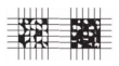
Coatings 15 00830 i005
5More than 65% above the previous levelCoatings 15 00830 i006
Table 5. Actual contact stress and maximum contact stress for different loads.
Loads/N361015
Actual contact stress/MPa600.00750.00909.091000.00
Maximum contact stress/MPa739.00931.081103.921263.68
Disclaimer/Publisher’s Note: The statements, opinions and data contained in all publications are solely those of the individual author(s) and contributor(s) and not of MDPI and/or the editor(s). MDPI and/or the editor(s) disclaim responsibility for any injury to people or property resulting from any ideas, methods, instructions or products referred to in the content.

