
Energy Sustainability, Resilience, and Climate Adaptability of Modular and Panelized Buildings with a Lightweight Envelope Integrating Active Thermal Protection: Part 2—Design and Implementation of an Experimental Prototype of a Building Module for Modular Buildings

 , , , , , and
Abstract
1. Introduction
- ▪
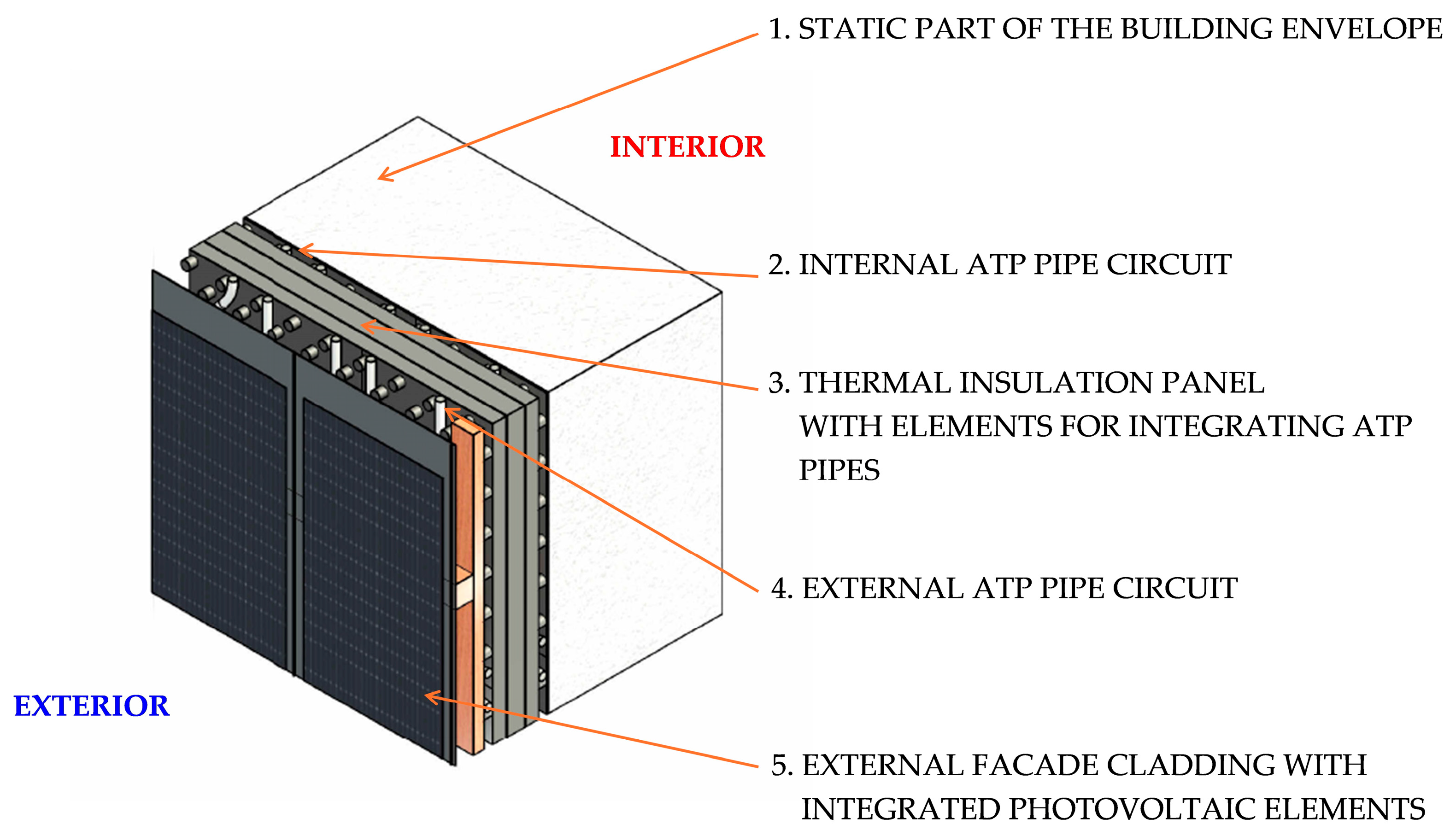
- Use of ATP not only as TB but also in the energy functions of large-area low-temperature radiant heating/high-temperature cooling and TABS in combination with additional heat/cooling sources (e.g., heat pumps), Figure 5(2).
- ▪
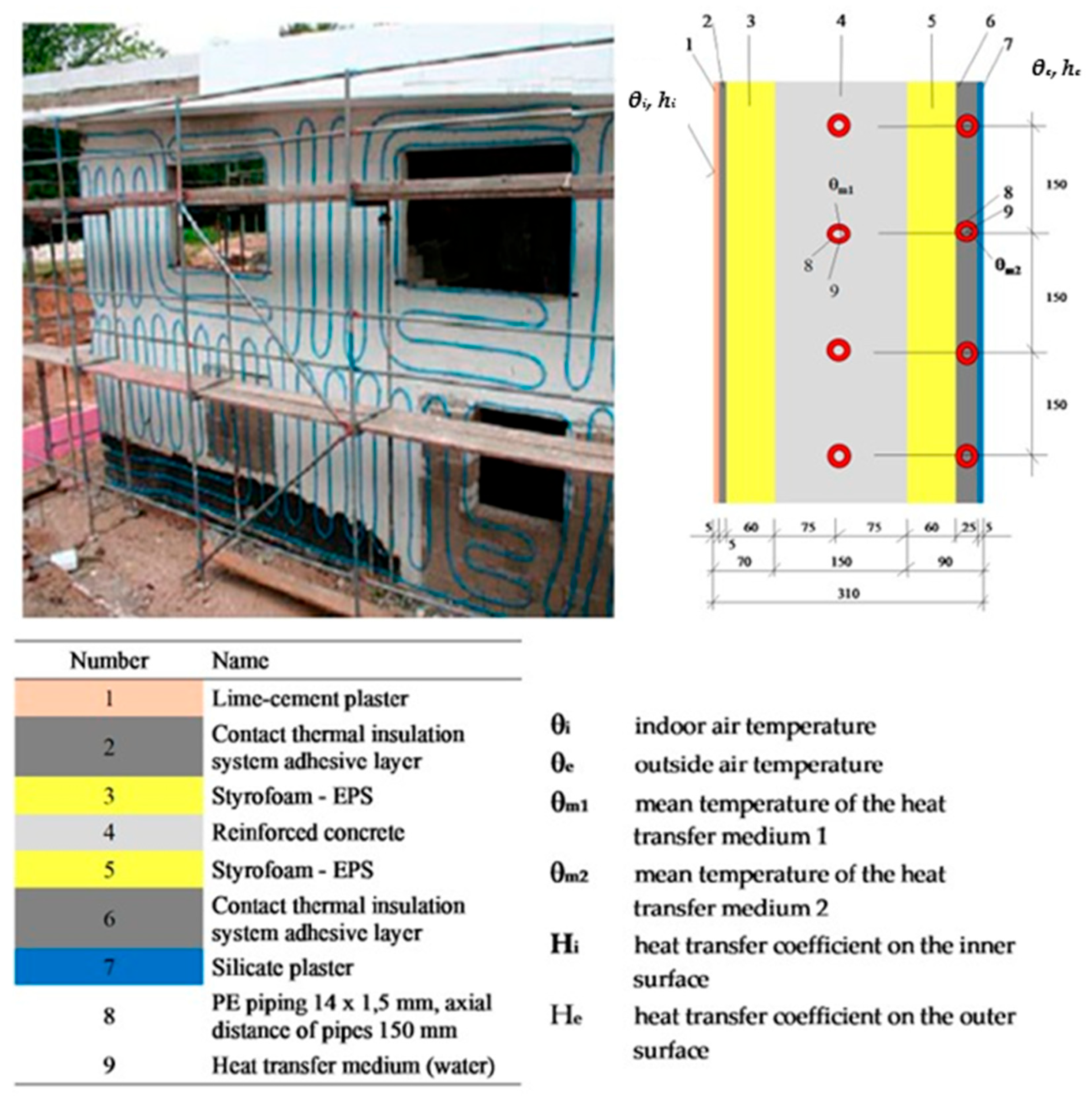
- Integration of energy-active elements (ATP) pipe circuits into thermal insulation panels, which are applied to buildings as a contact insulation system or even into entire modules of modular buildings (note: the ISOMAX system has been implemented in building structures using a classic wet system as large-area radiant wall heating), Figure 5(3).
- ▪
- Using external ATPs not only to eliminate heat loss or cool overheated facade surfaces but also to preheat DHW, Figure 5(4).
- ▪
- Integrating photovoltaic elements into the external structure of facade cladding, Figure 5(5).
- Low heating and cooling costs (reduction of heat loss through the thickness of thermal insulation).
- Speed of construction (construction is several times faster than conventional masonry buildings, which require a myriad of wet processes to construct).
- Healthier and more comfortable living (forced ventilation using heat recovery air handling units, ideally with enthalpic heat exchangers = heat + moisture recovery).
- High-strength (modern panel and module structures have the strength of a monolithic shell), larger usable area (these buildings provide 7%–10% more usable area than conventional masonry buildings).
- Stable insulation (the insulation core of modern modular and prefabricated buildings is strong and stable even after decades; it cannot get wet, sag, or misapplied as can happen with conventional prefabricated frame structures, which are technologically demanding).
- A certified system with guarantees (the production process is subject to regular inspection by a notified person, and each component must be certified).
- Environmental aspects and sustainability (modular and prefabricated buildings classified as timber buildings allow for the overall production process, the construction of the building, as well as the possibility of recycling the materials, thus significantly reducing CO2 production).
2. Materials and Methods
2.1. Overview of Scientific and Professional Studies
2.2. Development and Design of an Experimental Prototype of a Prefabricated Modul
2.3. The Use of Building Information Modeling (BIM)
3. Results
3.1. Results of the Development and Design of an Experimental Prototype of a Modul with ATP
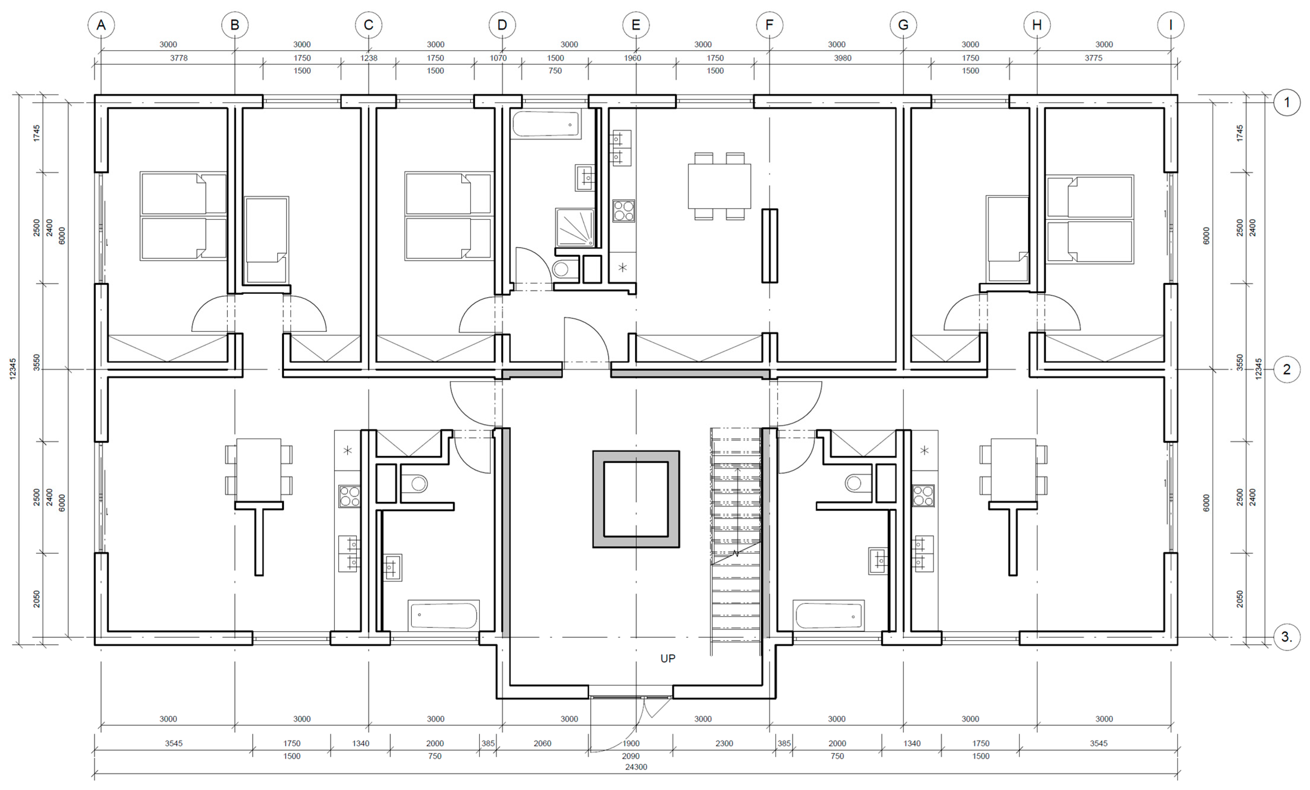
3.1.1. Location Description
3.1.2. Technological Prescription for the Implementation of ATP on a Prototype Building
Purpose of the Technological Regulation
Scope of Validity
General Information
Construction Preparation
- a.
- Readiness of the building, object, and structure
- b.
- Workplace readiness
- c.
- Preparation of the construction site
Materials Used
Technological Procedure of Works
- a.
- Preparatory work
- b.
- Semi-finished products (production, transport)
- c.
- Composition of work teams, equipment of work teams with tools and machinery
- d.
- Progress of work
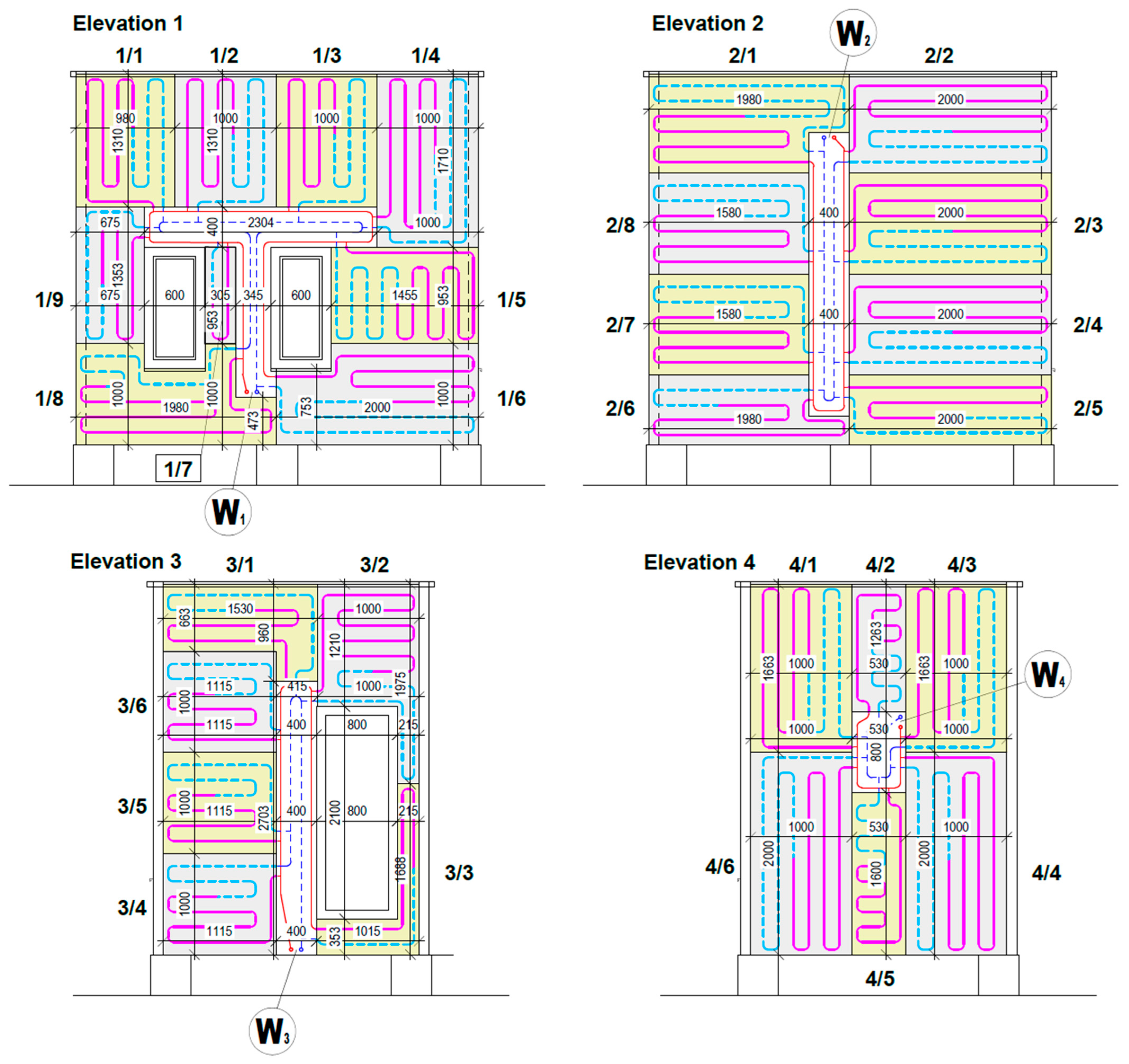
- Wall W1 and W3
- Cleaning of the substrate/exterior surface of the perimeter wall No. W1 of the prototype building module from any dust and dirt from the construction. Cleaning is to be carried out by plastering or vacuuming with an industrial vacuum cleaner.
- Levelling of the substrate as required and removal of protruding wooden elements of OSB boards, sawdust, and cuttings.
- Implementation of the adhesion bridge and priming of the substrate in two perpendicular layers with a primer designed for absorbent substrates (wood/wood–composite materials). Apply the coating with a roller, observing the specified consumption per m2.
- Technological break according to the primer manufacturer’s specifications.
- Drilling holes for the foundation strip into the load-bearing part of the cladding structure. Fitting the foundation strip to the level of the position of the lower edge of the base panel No. W1/8, S1/7, and W1/6 in the plane.
- Application of adhesive mortar with a trowel along the entire length of the free edge of the insulating part of the base panel, including a minimum of three separate mortar targets in the area. Apply the targets outside the pipework.
- Fit and glue the base panels into the space of the system aluminum base batten, or in the case of a timber batten, to the top level of such base batten.
- Take a technological break as necessary to allow the adhesive mortar to cure and to eliminate buckling/buckling when transferring the vertical load of the W1 panels located above.
- At the time of the technological pause, drill holes for the dowel bar into the load-bearing part of the envelope structure at wall W3.
- Set the dowel bar to the level of the position of the bottom edge of the base panel No. W3/4 and W3/3 using a spirit level in the plane.
- Then apply the adhesive mortar to the W3/4 and W3/3 base panels in the same way and fit to the face of the perimeter wall.
- The other panels above the level of the first row of walls W1 and W3 shall be fixed to the perimeter structure in the same way, using adhesive mortar applied around the entire edge of the free part of the insulation board and in a minimum of three separate targets in the panel area.
- The bonding of the remaining rows of panels is accomplished by alternating the W1 and W3 walls.
- The edges of the panels on walls W1 and W2 must be fitted on the corners with an overlap in the thickness of the insulation board (min. 100 mm).
- Wall W2 and W4
- The W2 and W4 wall is implemented in the same way.
- The edges of the panels on walls W3 and W4 are soldered to the level of the corner of the envelope of the prototype building module.
- After the base panels are installed, the anchoring of the supply and return ducts is carried out directly on the perimeter cladding of the prototype building module in the area of the omitted installation duct.
- This is followed by the connection of the ATP base panels to the supply and return piping, as well as the connection to the piping in the envelope of the prototype building module.
- After a positive inspection of the pipe connections, the sealing of the installation duct is carried out with an atypical-shaped mineral wool insulation element, which is manufactured from standard dimensions on site.
- Once the ducts have been sealed on all walls of the prototype modular cell, a reinforcement/protection layer will be implemented at the corners of the fitted ATP panels and the locations of the MW cover panels.
- The reinforcement layer is implemented in three steps: application of the adhesive mortar, placement of the reinforcing mesh, and closure with the reinforcing mortar by a wet-in-wet system.
- At corners, the overlaps of the reinforcing mesh over the edge of the corner must be kept to a minimum of 100 mm. The corners can also be reinforced with a system element, such as a corner beam.
- Mesh overlaps of min. 80 mm must also be maintained at the point of change of the insulation material, the overlapping junction of the installation duct, and the ATP base panels.
- Finally, a sealing profile is fitted in the joint of the attic flashing and the highest panel around the entire perimeter of the prototype building module.
- e.
- Organization of work in space and time
- f.
- Process labor intensity, unit cost, duration
- g.
- Treatment and protection of the product
- h.
- Finishing work (e.g., dismantling of ancillary structures) and readiness for downstream processes
- i.
- Inspection and test plan
- Initial check:
- Delivery of materials, panels, and related components (number, size, damage) and compliance with PD.
- Substrate cleanliness, moisture, and flatness.
- Location of penetrations for system connection.
- Climatic conditions for application of primer and adhesive mortar.
- Interoperative control:
- Position and flatness of the installation of the foundation bar.
- Number of coats and primer consumption.
- Consistency of adhesive mortar.
- Method and extent of application of adhesive mortar.
- Position of the base panels in accordance with the cladding plan.
- Width of overlap of the base panels at the corners of the prototype module.
- Position and anchoring of the piping for the system connection.
- Interconnection of the pipe panel system with the supply and return pipe in the ducts and connection to the interior penetrations.
- Output inspection and inspection of finished work:
- Functionality of the ATP pipe system.
- Overlaps of the reinforcement grid across the corner joints and the joints of the supplementary panels (on the installation channels) with the base panel.
- Sealing of the base panel and attic flashings.
Health and Safety at Work
Environmental Protection
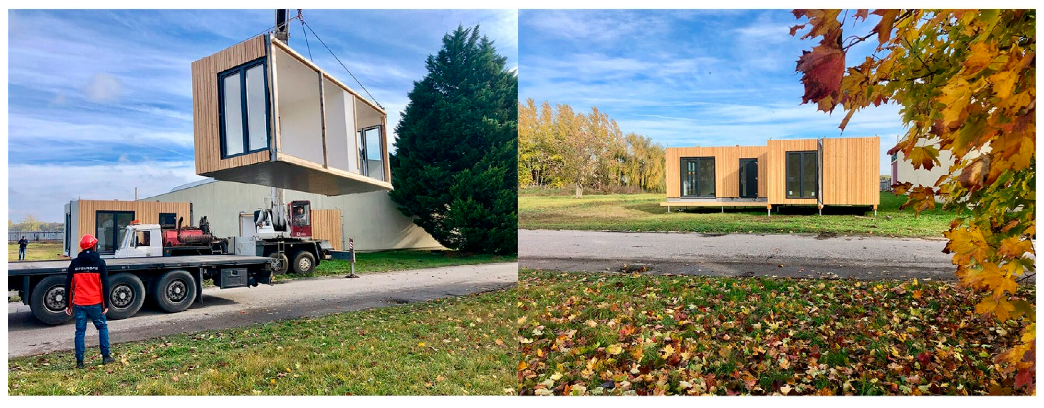
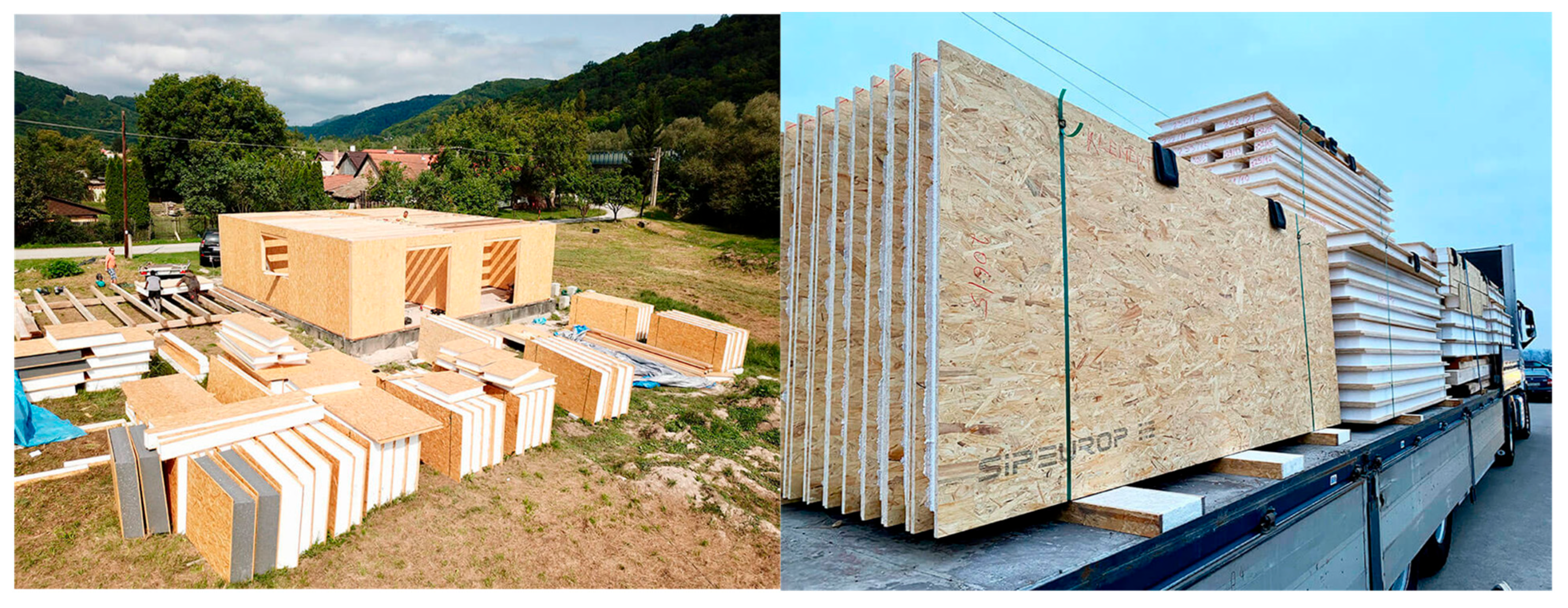
3.2. Construction Progress
4. Discussion
5. Conclusions
Author Contributions
Funding
Institutional Review Board Statement
Informed Consent Statement
Data Availability Statement
Acknowledgments
Conflicts of Interest
Abbreviations
| 3DCP | 3D concrete printing |
| ABE | Agrivoltaics building envelope |
| AEC | Architecture, engineering, and construction sector |
| ATP | Active thermal protection |
| BEM | Building energy modeling |
| BIM | Building information modeling |
| BIPV | Building-integrated photovoltaic |
| BPS | Building performance simulation |
| CAD | Computer aided design |
| CLT’s | Cross-laminated timbers |
| CO2 | Carbon dioxide |
| CV(RMSE) | The coefficient of variation coefficient of variation—root-mean-square error |
| EBAS | Energy-efficient building automation systems |
| EE | Electrical energy |
| EMF | Energy multifunctional facade |
| EPS | Expanded polystyrene |
| EU | European union |
| EUI | Energy use intensity |
| GFRP | Glass fiber–reinforced polymer |
| HCS | heat/cooling source |
| HVAC | Heating, ventilation, and air conditioning |
| IoT | Applications leveraging real-time data |
| LCA | Life cycle assessment |
| MICs | Modular integrated constructions |
| MKPC | Magnesium potassium phosphate cement |
| MW | mineral wool |
| nZEB | Near zero energy buildings |
| PD | project documentation |
| PRISMA | Systematic review with meta-analysis |
| PRH | Public rental housing |
| PUR | Polyurethane |
| PV | Photovoltaic |
| RES | Renewable energy sources |
| RtD | Research through design |
| RfD | Research for design |
| SVC | Scheduling variable controller |
| TABS | Thermally activated building systems |
| TB | Thermal barrier |
| TDP | Thermal discomfort percentage |
| UAV-BIM-BEM | Unmanned aerial vehicles—Building information modeling—Building energy model |
| UDI | Useful daylight illuminance |
| UN | United nations |
| WUFI | Walls was simulated using |
References
- Kalús, D.; Šimko, M.; Galváneková, M. Intelligent Facade System with Active Thermal Protection; Scholars’ Press: Stuttgart, Germany, 2014; p. 56. [Google Scholar]
- Kalús, D.; Gašparík, J.; Janík, P.; Kubica, M.; Šťastný, P. Innovative building technology implemented into facades with active thermal protection. Sustainability 2021, 13, 4438. [Google Scholar] [CrossRef]
- Krecké, E.D. Energetické Zariadenie Budov. Energy Equipment of Buildings. In Vestník ÚPV SR č.: 11/2005. Patent SK 284 751, 3 November 2005. [Google Scholar]
- ISOMAX. Available online: https://www.solinterra.si/en/history.html (accessed on 16 June 2025).
- ISOMAX. Available online: https://mojdom.zoznam.sk/nezaradene/byvanie-za-tepelnou-barierou-2-cast/ (accessed on 16 June 2025).
- Cvíčela, M. Analysis of Wall Energy Systems. Master’s Thesis, Faculty of Civil Engineering, Slovak University of Technology in Bratislava, Bratislava, Slovakia, 2011; p. 119, SVF-13422-17675. [Google Scholar]
- Janík, P. Optimization of Energy Systems with Long-Term Heat Accumulation. Master’s Thesis, Faculty of Civil Engineering, Slovak University of Technology in Bratislava, Bratislava, Slovakia, 2013; p. 185, SvF-13422-16657. [Google Scholar]
- UTILITY MODEL SK 5749 Y1 (UTILITY MODEL): Method of Operation of a Combined Construction-Energy System of Buildings and Equipment. Date of Entry into Force of the Utility Model: 1.4.2011. In Vestník ÚPV SR č.: 5/2011, 23p. Spôsob Prevádzky Kombinovaného Stavebno-Energetického Systému Budov a Zariadenie: Číslo Prihlášky 5027-2010, Zverejnená 8. 11. 2010 vo Vestníku ÚPV SR č. 11/2010; Úrad Priemyselného Vlastníctva Slovenskej Republiky: Banská Bystrica, Slovakia, 2011; 23p. Available online: https://wbr.indprop.gov.sk/WebRegistre/UzitkovyVzor/Detail/5027-2010 (accessed on 23 March 2025).
- UTILITY MODEL SK 5729 Y1 (UTILITY MODEL): Samonosný Tepelnoizolačný Panel pre Systémy s Aktívnym Riadením Prechodu Tepla. [Self-Supporting Thermal Insulation Panel for Systems with Active Heat Transfer Control]. Date of Entry into Force of the Utility Model: 28.2.2011. In Vestník ÚPV SR No. 4/2011, Banská Bystrica, Slovak Republic, 32 p. Samonosný Tepelnoizolačný Panel pre Systémy s Aktívnym Riadením Prechodu Tepla: Číslo Prihlášky UV 5030-2010, Zverejnená 7. 10. 2010 vo Vestníku ÚPV SR č. 10/2010; Úrad Priemyselného Vlastníctva Slovenskej Republiky: Banská Bystrica, Slovakia, 2011; 32p. Available online: https://wbr.indprop.gov.sk/WebRegistre/UzitkovyVzor/Detail/5030-2010 (accessed on 23 March 2025).
- UTILITY MODEL SK 5725 Y1 (UTILITY MODEL): Tepelnoizolačný Panel pre Systémy s Aktívnym Riadením Prechodu Tepla: Číslo Prihlášky UV 5031-2010, Zverejnená 7.10. 2010 vo Vestníku ÚPV SR č. 10/2010; Úrad Priemyselného Vlastníctva Slovenskej Republiky: Banská Bystrica, Slovakia, 2011; 63p. Available online: https://wbr.indprop.gov.sk/WebRegistre/UzitkovyVzor/Detail/5031-2010 (accessed on 23 March 2025).
- EUROPEAN PATENT EP 2 572 057 B1. Heat Insulating Panel with Active Regulation of Heat Transition. International Application Number: PCT/SK2011/000004, International Publication Number: WO 2011/146025 (24.11.2011 Gazette 2011/47). 15 October 2014. 67p. Available online: https://register.epo.org/application?number=EP11716446&tab=main&lng=en10 (accessed on 23 March 2025).
- Šimko, M.; Krajčík, M.; Šikula, O.; Šimko, P.; Kalús, D. Insulation panels for active control of heat transfer in walls operated as space heating or as a thermal barrier: Numerical simulations and experiments. Energy Build. 2018, 158, 135–146. [Google Scholar] [CrossRef]
- Kalús, D.; Janík, P.; Kubica, M. Experimental house EB2020–Research and experimental measurements of an energy roof. Energy Build. 2021, 248, 111172. [Google Scholar] [CrossRef]
- Kalús, D.; Straková, Z.; Kubica, M. Energy Balance of a Low Energy House with Building Structures with Active Heat Transfer Control. Period. Polytech. Mech. Eng. 2021, 65, 246–251. [Google Scholar] [CrossRef]
- Kalús, D.; Cvíčela, M.; Janík, P.; Kubica, M. Combined Building-Energy Systems with Heat Transfer Control by Building Constructions using RES. In IOP Conference Series: Materials Science and Engineering; IOP Publishing: Bristol, UK, 2021; Volume 1203, p. 032091. Available online: https://iopscience.iop.org/article/10.1088/1757-899X/1203/3/032091/meta (accessed on 15 July 2021).
- Kalús, D.; Janík, P.; Koudelková, D.; Mučková, V.; Sokol, M. Contribution to research on ground heat storages as part of building energy systems using RES. Energy Build. 2022, 267, 112125. [Google Scholar] [CrossRef]
- SIP-EUROPE Group–Company Website. Available online: https://www.sipeurope.eu/sipeurope-group/ (accessed on 23 March 2025).
- Chang, S.J.; Kang, Y.; Yun, B.Y.; Yang, S.; Kim, S. Assessment of effect of climate change on hygrothermal performance of cross-laminated timber building envelope with modular construction. Case Stud. Therm. Eng. 2021, 28, 101703. [Google Scholar] [CrossRef]
- Volpe, S.; Sangiorgio, V.; Petrella, A.; Coppola, A.; Notarnicola, M.; Fiorito, F. Building envelope prefabricated with 3D printing technology. Sustainability 2021, 13, 8923. [Google Scholar] [CrossRef]
- Maracchini, G.; D’Orazio, M. Improving the livability of lightweight emergency architectures: A numerical investigation on a novel reinforced-EPS based construction system. Build. Environ. 2022, 208, 108601. [Google Scholar] [CrossRef]
- Blanchet, P.; Perez, C.; Cabral, M.R. Wood building construction: Trends and opportunities in structural and envelope systems. Curr. For. Rep. 2024, 10, 21–38. [Google Scholar] [CrossRef]
- Sarmento, R.; Posani, M.; Fernandes, P.; Rodrigues, A.M.; Gomes, M.G. Energy efficiency in modular emergency shelters: Impact of envelope finishings and shadowing. J. Build. Eng. 2024, 94, 110029. [Google Scholar] [CrossRef]
- Jia, Y.H.; Niu, Z.R.; Qiao, W.T.; Zhang, X.; Wang, R.Q.; Mei, S.Q. Thermal performance study on the outer wall of a new ultra-low energy modular wall prefabricated building. J. Build. Eng. 2024, 98, 111382. [Google Scholar] [CrossRef]
- Hu, Y.; Ai, Z.; Zhang, G.; Zong, J.; Liu, Z. Analyzing the impact of design factors on external walls in lightweight modular construction based on life-cycle analysis: Energy, economic, and environmental trade-offs. J. Build. Eng. 2025, 11, 112090. [Google Scholar] [CrossRef]
- Zhang, Y.; Chen, T.; Gasparri, E.; Lucchi, E.A. Modular Agrivoltaics Building Envelope Integrating Thin-Film Photovoltaics and Hydroponic Urban Farming Systems: A Circular Design Approach with the Multi-Objective Optimization of Energy, Light, Water and Structure. Sustainability 2025, 17, 666. [Google Scholar] [CrossRef]
- Parracho, D.F.; Nour El-Din, M.; Esmaeili, I.; Freitas, S.S.; Rodrigues, L.; Poças Martins, J.; Corvacho, H.; Delgado, J.M.; Guimarães, A.S. Modular Construction in the Digital Age: A Systematic Review on Smart and Sustainable Innovations. Buildings 2025, 15, 765. [Google Scholar] [CrossRef]
- Gong, Q.; Ding, W.; Liu, X.; Zeng, Y.; Adu, E.; Shao, H. Multi-objective Optimization Framework for the Building Envelope of Public Rental Housing in China’s Cold Regions. J. Build. Eng. 2025, 104, 112261. [Google Scholar] [CrossRef]
- Li, Y.; Chen, L. A study on database of modular façade retrofitting building envelope. Energy Build. 2020, 214, 109826. [Google Scholar] [CrossRef]
- Huang, B.; Wang, Y.; Lu, W.; Cheng, M. Fabrication and energy efficiency of translucent concrete panel for building envelope. Energy 2022, 248, 123635. [Google Scholar] [CrossRef]
- Pless, S.; Podder, A.; Kaufman, Z.; Klammer, N.; Dennehy, C.; Muthumanickam, N.K.; Rothgeb, S.; Louis, J.; Swanson, C.; Wallace, H.; et al. The Energy in Modular (EMOD) Buildings Method: A Guide to Energy-Efficient Design for Industrialized Construction of Modular Buildings; National Renewable Energy Lab. (NREL): Golden, CO, USA, 2022. [Google Scholar] [CrossRef]
- Kysela, P.; Ponechal, R.; Michálková, D. Airtightness of a critical joint in a timber-based building affected by the seasonal climate change. Buildings 2023, 13, 698. [Google Scholar] [CrossRef]
- Sah, T.P.; Lacey, A.W.; Hao, H.; Chen, W. Prefabricated concrete sandwich and other lightweight wall panels for sustainable building construction: State-of-the-art review. J. Build. Eng. 2024, 89, 109391. [Google Scholar] [CrossRef]
- Mohammed, M.A.; Budaiwi, I.M.; Al-Osta, M.A.; Abdou, A.A. Thermo-Environmental Performance of Modular Building Envelope Panel Technologies: A Focused Review. Buildings 2024, 14, 917. [Google Scholar] [CrossRef]
- Pan, Y.; Zhu, M.; Lv, Y.; Yang, Y.; Liang, Y.; Yin, R.; Yang, Y.; Jia, X.; Wang, X.; Zeng, F.; et al. Building energy simulation and its application for building performance optimization: A review of methods, tools, and case studies. Adv. Appl. Energy 2023, 10, 100135. [Google Scholar] [CrossRef]
- Alhammad, M.; Eames, M.; Vinai, R. Enhancing building energy efficiency through building information modeling (BIM) and building energy modeling (BEM) integration: A systematic review. Buildings 2024, 14, 581. [Google Scholar] [CrossRef]
- Guo, H.; Chen, Z.; Chen, X.; Yang, J.; Song, C.; Chen, Y. UAV-BIM-BEM: An automatic unmanned aerial vehicles-based building energy model generation platform. Energy Build. 2025, 328, 115120. [Google Scholar] [CrossRef]
- Lydon, G.P.; Caranovic, S.; Hischier, I.; Schlueter, A. Coupled simulation of thermally active building systems to support a digital twin. Energy Build. 2019, 202, 109298. [Google Scholar] [CrossRef]
- Krušinský, P.; Kysela, P.; Pisca, P. Simulations of airflow in the roof space of a gothic sanctuary using cfd models. Energies 2021, 14, 3694. [Google Scholar] [CrossRef]
- Ponechal, R.; Barňák, P.; Ďurica, P. Comparison of simulation and measurement in a short-term evaluation of the thermal comfort parameters of an office in a low-carbon building. Buildings 2022, 12, 349. [Google Scholar] [CrossRef]
- An, J.; Wu, Y.; Gui, C.; Yan, D. Chinese prototype building models for simulating the energy performance of the nationwide building stock. In Building Simulation; Tsinghua University Press: Beijing, China, 2023; Volume 16, pp. 1559–1582. [Google Scholar]
- Liu, Z.; Zhang, X.; Sun, Y.; Zhou, Y. Advanced controls on energy reliability, flexibility and occupant-centric control for smart and energy-efficient buildings. Energy Build. 2023, 297, 113436. [Google Scholar] [CrossRef]
- Kiaulakis, A.; Vilutienė, T.; Šarka, V.; Šarkienė, E.; Rogoža, A. The Conceptual Model of the BIM4NZEB-DS System for Selecting Technological Variants of Rational Passive Energy Efficiency Measures for a Sustainable Building. Vilnius Univ. Proc. 2023, 37, 41–47. [Google Scholar] [CrossRef]
- Zhang, Z.; Yao, J.; Zheng, R. Multi-Objective optimization of building energy saving based on the randomness of energy-related occupant behavior. Sustainability 2024, 16, 1935. [Google Scholar] [CrossRef]
- Muhič, S.; Čikić, A.; Perić, M. Building with an Active Thermal Protection in Combination with High Share of Renewable Energy Sources Use. In Proceedings of the 2024 9th International Conference on Smart and Sustainable Technologies (SpliTech), Bol and Split, Croatia, 25–28 June 2024; IEEE: New York City, NY, USA, 2024; pp. 1–4. [Google Scholar]
- Kozlovska, M.; Petkanic, S.; Vranay, F.; Vranay, D. Enhancing energy efficiency and building performance through BEMS-BIM integration. Energies 2023, 16, 6327. [Google Scholar] [CrossRef]
- Al Khiro, H.A.; Boukhanouf, R. Analytical and computer modelling of a thermo-mechanical vapour compression system for space air conditioning in buildings. Energy Convers. Manag. 2025, 323, 119252. [Google Scholar] [CrossRef]
- Fawaier, M.; Róbert, G.; Bokor, B. Simulation study of dynamic building insulation with transpired solar collectors. Energy Rep. 2024, 12, 1325–1343. [Google Scholar] [CrossRef]
- Zhangabay, N.; Oner, A.; Rakhimov, M.; Tursunkululy, T.; Abdikerova, U. Thermal Performance Evaluation of a Retrofitted Building with Adaptive Composite Energy-Saving Facade Systems. Energies 2025, 18, 1402. [Google Scholar] [CrossRef]
- Li, F.; Peng, T.; Chen, J.; Wu, J.; Cao, J.; Luo, H.; Luo, J.; Wang, Z. Prediction and strategies of buildings’ energy consumption: A review of modeling approaches and energy-saving technologies. Int. J. Green Energy 2025, 15, 1–36. [Google Scholar] [CrossRef]
- STN 73 0540-2+Z1+Z2:2019; Tepelná Ochrana Budov. Tepelnotechnické Vlastnosti Stavebných Konštrukcií a Budov Časť 2 Funkčné Požiadavky. (Thermal Protection of Buildings. Thermal Performance of Building Structures and Buildings Part 2 Functional Requirements). Slovak Office of Standards, Metrology and Testing: Bratislava, Slovakia, 2019.
- STN EN ISO 9001:2016; Quality Management Systems. Requirements. Slovak Office of Standards, Metrology and Testing: Bratislava, Slovakia, 2016; and its amendments (2018 and 2025).
- Sacks, R.; Eastman, C.; Lee, G.; Teicholz, P. BIM Handbook, a Guide to Building Information Modeling for Owners, Managers, Designers, Engineers, and Contractors, 3rd ed.; John Wiley & Sons Inc.: New Jersey, NY, USA, 2018. [Google Scholar] [CrossRef]
- Funtík, T.; Pasiar, M.; Erdélyi, J.; Hlavatá, J.; Kaleja, P.; Mayer, P. Building Information Modeling; Eurostav: Bratislava, Slovakia, 2018; p. 205. ISBN 978-80-89228-56-0. [Google Scholar]
- Czmoch, I.; Pękala, A. Traditional design versus BIM based design. Procedia Eng. 2014, 91, 210–215. [Google Scholar] [CrossRef]
- Funtík, T.; Makýš, P.; Ďubek, M.; Erdélyi, J.; Honti, R.; Cerovšek, T. The Status of Building Information Modeling Adoption in Slovakia. Buildings 2023, 13, 2997. [Google Scholar] [CrossRef]
- Erdélyi, J.; Honti, R.; Funtík, T.; Mayer, P.; Madiev, A. Verification of Building Structures Using Point Clouds and Building Information Models. Buildings 2022, 12, 2218. [Google Scholar] [CrossRef]
- STN EN 12831-1 (060210); Energetická Hospodárnosť Budov. Metóda Výpočtu Projektovaného Tepelného Príkonu. Časť 1: Tepelný Príkon, Modul M3-3. (Energy Performance of Buildings. Method of Calculation of Design Heat Input. Part 1: Heat Input, Module M3-3). Slovak Office of Standards, Metrology and Testing: Bratislava, Slovakia, 2019.
- STN EN 17248 (383350); Potrubné Systémy Diaľkového Vykurovania a Diaľkového Chladenia. Termíny a Definície. (Piping Systems for District Heating and District Cooling. Terms and Definitions). Slovak Office of Standards, Metrology and Testing: Bratislava, Slovakia, 2020.
- Straková, Z.; Marková, J. A New Perspective on Residential Building Ventilation from the Point of View of Achieving the Desired Indoor Air Quality Using Different Ventilation Systems. Slovak J. Civ. Eng. 2023, 31, 45–51. [Google Scholar] [CrossRef]
- Strenk, T.; Straková, Z. Assessment of the quality of the indoor environment in flats after complex renovation of the building. In Indoor Climate of Buildings 2022, Proceedings of the ICB 2022, 33rd Annual and 11th International Conference, Nový Smokovec, Slovakia, 4–6 December 2022; SSTP: Bratislava, Slovakia, 2022; pp. 106–113. ISBN 978-80-8284-004-2. [Google Scholar]
- Vargová, A.; Muellner, H.; Exel, R.; Rychtáriková, M. Impact of sound insulation quality in dwellings on its financial value. J. Acoust. Soc. Am. 2017, 141, 3931. [Google Scholar] [CrossRef]


| Geographical Zone (City) | Height Above Sea Level (m) | Outdoor Design Temperature θe (°C) | Average Annual Outdoor Temperature θe,m (°C) | Average Outdoor Temperature in the Heating Period θe,average (°C) | The Number of Days of the Heating Period n (-) |
|---|---|---|---|---|---|
| Bratislava | 142 | −11 | 9.9 | 4.3 | 208 |
| Košice | 205 | −13 | 8.4 | 3.3 | 226 |
| Nitra | 190 | −11 | 9.6 | 4.1 | 212 |
| Prešov | 257 | −15 | 8.3 | 3.1 | 226 |
| Trnava | 146 | −11 | 9.5 | 4.0 | 214 |
| Žilina | 344 | −15 | 7.2 | 3.3 | 246 |
Disclaimer/Publisher’s Note: The statements, opinions and data contained in all publications are solely those of the individual author(s) and contributor(s) and not of MDPI and/or the editor(s). MDPI and/or the editor(s) disclaim responsibility for any injury to people or property resulting from any ideas, methods, instructions or products referred to in the content. |
© 2025 by the authors. Licensee MDPI, Basel, Switzerland. This article is an open access article distributed under the terms and conditions of the Creative Commons Attribution (CC BY) license (https://creativecommons.org/licenses/by/4.0/).
Share and Cite
Kalús, D.; Mučková, V.; Straková, Z.; Ingeli, R.; Antošová, N.; Šťastný, P.; Ďubek, M.; Füri, M.; Bolček, M. Energy Sustainability, Resilience, and Climate Adaptability of Modular and Panelized Buildings with a Lightweight Envelope Integrating Active Thermal Protection: Part 2—Design and Implementation of an Experimental Prototype of a Building Module for Modular Buildings. Coatings 2025, 15, 781. https://doi.org/10.3390/coatings15070781
Kalús D, Mučková V, Straková Z, Ingeli R, Antošová N, Šťastný P, Ďubek M, Füri M, Bolček M. Energy Sustainability, Resilience, and Climate Adaptability of Modular and Panelized Buildings with a Lightweight Envelope Integrating Active Thermal Protection: Part 2—Design and Implementation of an Experimental Prototype of a Building Module for Modular Buildings. Coatings. 2025; 15(7):781. https://doi.org/10.3390/coatings15070781
Chicago/Turabian StyleKalús, Daniel, Veronika Mučková, Zuzana Straková, Rastislav Ingeli, Naďa Antošová, Patrik Šťastný, Marek Ďubek, Mária Füri, and Martin Bolček. 2025. "Energy Sustainability, Resilience, and Climate Adaptability of Modular and Panelized Buildings with a Lightweight Envelope Integrating Active Thermal Protection: Part 2—Design and Implementation of an Experimental Prototype of a Building Module for Modular Buildings" Coatings 15, no. 7: 781. https://doi.org/10.3390/coatings15070781
APA StyleKalús, D., Mučková, V., Straková, Z., Ingeli, R., Antošová, N., Šťastný, P., Ďubek, M., Füri, M., & Bolček, M. (2025). Energy Sustainability, Resilience, and Climate Adaptability of Modular and Panelized Buildings with a Lightweight Envelope Integrating Active Thermal Protection: Part 2—Design and Implementation of an Experimental Prototype of a Building Module for Modular Buildings. Coatings, 15(7), 781. https://doi.org/10.3390/coatings15070781