Article

The Influence of Direct Aging on TiB2/Al–Si–Mg Composites Fabricated by LPBF: Residual Stress, Mechanical Properties and Microstructure

1
AVIC Chengdu Aircraft Industrial (Group) Co., Ltd., Chengdu 610073, China
2
State Key Laboratory of Metal Matrix Composites, Shanghai Jiao Tong University, Shanghai 200240, China
3
School of Materials Science & Engineering, Shanghai Jiao Tong University, Shanghai 200240, China
4
SJTU Paris Elite Institute of Technology, Shanghai Jiao Tong University, Shanghai 200240, China
*
Author to whom correspondence should be addressed.
Coatings 2025, 15(7), 780; https://doi.org/10.3390/coatings15070780
Submission received: 28 May 2025 / Revised: 19 June 2025 / Accepted: 23 June 2025 / Published: 2 July 2025
(This article belongs to the Special Issue Advanced Surface Technology and Application)

Abstract

This study systematically investigates the effects of various direct aging (DA) treatments on the residual stress, mechanical properties, and microstructure of laser powder bed fusion (LPBF) fabricated TiB2/AlSi7Mg composites. The results demonstrate that during aging at 120 °C, the hardness exhibits a typical age-hardening behavior. The residual stress relief rate increased to 45.1% after 336 h, although the stress relief rate significantly diminished over time. Increasing the aging temperature effectively enhanced residual stress removal efficiency, with reductions of approximately 40% and 62% observed after aging at 150 °C for 4 h and 190 °C for 8 h, respectively. Regarding mechanical properties, aging at 150 °C for 4 h resulted in an optimal synergy in yield strength (YS = 358 MPa) and elongation (EL = 9.2%), followed by aging at 190 °C for 8 h with YS of 320 MPa and EL of 7.0%. Microstructural analysis revealed that low temperature aging promotes the formation of nanoscale Si precipitates, which enhance strength through the Orowan mechanism. In contrast, high temperature annealing disrupts the metastable cellular structure, leading to the loss of strengthening effects. This work provides fundamental insights for effective residual stress management and performance optimization of LPBF Al–Si–Mg alloys.

Graphical Abstract

1. Introduction

Laser powder bed fusion (LPBF), as a disruptive innovation in the field of additive manufacturing, enables the fabrication of complex geometries through a layer-by-layer digital building process, thereby overcoming the geometric constraints inherent in conventional manufacturing techniques. Owing to its submillimeter resolution and exceptional material utilization efficiency, LPBF has demonstrated irreplaceable advantages in high-end applications such as aerospace precision components and biomedical implants [1]. By discretizing a three-dimensional model into micron-scale two-dimensional slices, LPBF employs a high-energy laser to selectively melt metal powders and achieve metallurgical bonding between successive layers. This process fundamentally breaks the limitations of subtractive manufacturing and offers a novel solution for the efficient production of lightweight and functionally integrated components.
Al–Si–Mg alloys, especially near-eutectic compositions such as AlSi7Mg and AlSi10Mg, are widely adopted in LPBF due to their low hot-cracking susceptibility, high laser absorptivity, and excellent melt pool stability [2,3]. In recent years, significant progress has been made in modifying the solidification microstructure through the incorporation of TiB2 nanoparticles [4,5,6,7]. TiB2 enhances not only laser absorption and defect mitigation but also acts as an effective heterogeneous nucleation agent, promoting grain refinement and facilitating the columnar-to-equiaxed transition (CET). Studies have demonstrated that TiB2/Al–Si–Mg composites fabricated by LPBF can achieve a relative density exceeding 99.5%, while exhibiting a yield strength (YS) that is approximately 40% higher than that of conventional cast alloys, thereby offering a remarkable combination of strength and ductility [5,8]. The incorporation of TiB2 effectively addresses challenges related to printability and mechanical performance in LPBF Al–Si–Mg alloys, thereby advancing their development and expanding their potential applications. This further extends their application potential in high-strength scenarios, such as aerospace brackets, automotive heat exchangers, and rail transit equipment [9].
However, metallic components fabricated via LPBF often suffer from significant residual stresses, which severely compromise their service performance [10,11,12]. These stresses originate inherently from the rapid melting and solidification dynamics characteristic of the LPBF process. Under extreme processing conditions—such as laser energy densities reaching up to 106 W/cm2—the melt pool experiences ultra-high cooling rates (103–106 K/s) and steep thermal gradients (ΔT > 2000 K/mm). Such non-equilibrium thermal cycling induces heterogeneous thermal expansion and contraction behavior across different regions of the material. Specifically, compressive stresses typically accumulate in the rapidly solidified center of the melt pool, while adjacent heat-affected zones (HAZs), which experience delayed contraction, develop tensile stresses [10,12,13]. The alternating distribution of these stress types results in a stratified residual stress profile dominated by Type I residual stresses. The vector superposition of these stresses is particularly pronounced at geometric discontinuities, such as overhangs and thin-walled junctions [14,15]. As residual stresses accumulate, they can initiate microcrack formation during the build process. Upon removal of the component from the build platform, the sudden release of accumulated residual stresses can result in significant distortion, warping, or even catastrophic cracking [11].
Conventional heat treatments, such as annealing and T6 treatment, have been shown to effectively relieve residual stresses in LPBF Al–Si–Mg alloys. For instance, Wang et al. [16] performed an annealing treatment at 300 °C for 3 h on AlSi7Mg alloys produced via LPBF, achieving a residual stress reduction of up to 87.6%. However, this treatment led to a marked decrease in YS—from 368 MPa to 226 MPa—representing a reduction of nearly 40%. Similarly, Gianluca et al. [17] applied a T6 treatment, which included solution treatment at 510 °C for 10 min followed by water quenching and aging at 160 °C for 6 h, to LPBF AlSi10Mg alloys. Although residual stresses were completely relieved, the ultimate tensile strength (UTS) dropped by approximately 45%. These findings underscore a pronounced thermodynamic incompatibility between conventional high-temperature treatments and the metastable microstructures formed during rapid solidification in LPBF, leading to significant strength degradation. This presents a critical challenge in fulfilling the dual requirements of high strength and low residual stress required for aerospace applications. Direct aging (DA), a low-temperature post-processing strategy, offers a promising alternative by facilitating precipitation strengthening while preserving the three-dimensional dual-phase cellular nanostructure (3D-DPCN) [7]. DA has the potential to improve mechanical performance by tailoring the size and distribution of precipitates. However, studies assessing its effectiveness in alleviating residual stresses remain limited. In particular, the coupled effects of aging temperature and time on microstructural reconstruction, stress relaxation, and mechanical performance have not yet been systematically investigated.
This study systematically investigates TiB2/AlSi7Mg composites fabricated by LPBF to elucidate the effects of low-temperature aging parameters, namely temperature and duration, on the evolution of multiscale microstructures, including melt pool morphology, grain structure, sub-grain-scale non-equilibrium solidification features, and nanoscale precipitates, as well as residual stress states and mechanical properties such as hardness, tensile strength, and elongation. By establishing a correlation among post-processing parameters, microstructural characteristics, and mechanical performance, the present work elucidates the competitive interplay between strengthening mechanisms and stress relaxation occurring during the DA process. The findings provide both theoretical insights and experimental data to support the development of efficient post-processing strategies tailored to LPBF Al–Si–Mg alloys for engineering applications.

2. Materials and Methods

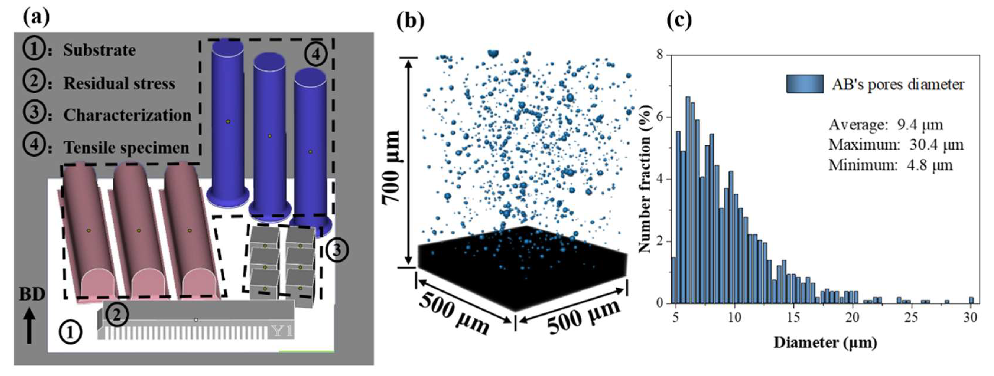
2.1. Materials Fabrication and Heat Treatment

The alloy powders used for LPBF fabrication were produced via gas atomization, exhibiting a particle size distribution of 15–53 μm. The TiB2 particles were introduced in situ through a salt–metal reaction during alloy ingot preparation prior to atomization, and the content of TiB2 particles is 2 wt%, which is enough to change columnar grains to fine equiaxed grains [18]. The chemical compositions of both the composite powders and the LPBF samples were determined via inductively coupled plasma atomic emission spectroscopy (ICP-AES, Avio 500 (PerkinElmer Inc., Waltham, MA, USA), as summarized in Table 1. No significant compositional changes were observed between the powders and the samples.
The LPBF as-built (AB) samples were fabricated by using an EOS M290 system (EOS GmbH Electro Optical Systems Krailling, Germany). The optimized process parameters were as follows: laser power of 340 W, scanning speed of 1300 mm/s, layer thickness of 30 μm, hatch spacing of 120 μm, and a scan rotation angle of 67° between successive layers. Representative samples fabricated by LPBF are shown in Figure 1a, where BD denotes the building direction. Region 1 (white area) corresponds to the build substrate. Region 2 denotes a cantilever beam specimen with dimensions of 12 mm × 72 mm × 9 mm, utilized for residual stress measurements. Region 3 represents a cubic specimen measuring 10 × 10 × 10 mm3, used for hardness testing and microstructural characterization. Region 4 indicates rod-shaped specimens in two orientations: horizontal samples denoted by red and vertical samples denoted by blue. Each specimen is a cylinder with a length of 70 mm and a diameter of 10 mm. These rod specimens were subsequently machined into dog-bone tensile specimens featuring a 5 mm diameter and 67 mm gauge length in accordance with ASTM E8 standards(E8M-24) for tensile testing. The quality of the printed samples was evaluated using X-ray micro-computed tomography (X-ray μ-CT, ZEISS Xradia 520 Versa (Carl Zeiss AG, Oberkochen, Germany)), as depicted in Figure 1b,c. The specimens exhibited a low porosity of approximately 0.3%, with an average pore diameter of 9.4 μm and a maximum pore size not exceeding 30.4 μm, demonstrating excellent densification and forming quality.
Heat treatments were performed in a Nabertherm N60/85HA (Nabertherm GmbH, Lilienthal, Germany) furnace involving heating to the target temperature followed by cooling to room temperature. The heat treatment regimes investigated in this study comprised direct aging at 120 °C for durations ranging from 0 to 336 h, direct aging at 150 °C for 4 h, direct aging at 190 °C for 8 h, and annealing at 280 °C for 2 h.

2.2. Microstructure Characterization

All specimens subjected to microstructural characterization were prepared according to standard metallographic procedures, which formed the basis for subsequent analyses. Scanning electron microscopy (SEM) was performed using a MAIA 3 field emission SEM (TESCAN ORSAY HOLDING a.s., Brno, Czech Republic). The samples were etched for 1 min in Keller’s reagent (home-made), comprising 2.5 vol% HNO3, 1.5 vol% HCl, 1 vol% HF, and 95 vol% H2O. Electron backscatter diffraction (EBSD) analysis was performed on a dual-beam TESCAN LYRA3 field emission SEM (TESCAN ORSAY HOLDING a.s., Brno, Czech Republic) equipped with an Oxford Nordlys Max3 EBSD detector (Oxford Instruments plc, Abingdon, UK). Prior to EBSD measurements, samples were mechanically polished and finished using a Leica EM TIC 3X triple-ion beam system (Leica Microsystems GmbH, Wetzlar, Germany) with a step size of 0.2 μm. Further microstructural and elemental distribution analyses were conducted using scanning transmission electron microscopy (STEM) on a Talos 200X G2 (Thermo Fisher Scientific Inc., Hillsboro, OR, USA) equipped with energy dispersive X-ray spectroscopy (EDS). Thin foil specimens of approximately 30 μm thickness were prepared using a precision ion polishing system (Gatan PIPS 695) (Gatan Inc., Pleasanton, CA, USA).

2.3. Mechanical Tests

Hardness measurements were performed using an EZ-mat CARAT 930 fully automatic micro-Vickers hardness tester (Advanced Testing Machines GmbH, Cologne, Germany), applying a constant load of 10 N for 15 s. Five indentations were performed on each sample, and the average hardness value was reported to reduce measurement errors. Tensile tests were conducted on a Zwick/Roell Z100 machine (ZwickRoell GmbH & Co. KG, Ulm, Germany) under a controlled strain rate of 10−3 s−1. To ensure result reliability, three replicates were performed for each condition. Residual stress measurement techniques generally encompass destructive methods, including hole-drilling and contour methods, as well as non-destructive techniques such as X-ray diffraction and neutron diffraction. To better align with industrial requirements while minimizing time and costs, this study employed a simple stress-relief method. Specifically, the cantilever beam specimens indicated as region 2 in Figure 1a were machined via wire electrical discharge machining to isolate each supporting fin from the substrate, leaving only the free end connected at the location labeled Y1. The maximum deflection of the cantilever beam, resulting from residual stress release, was subsequently measured to indicate the residual stress level under various treatment conditions [14,19].

3. Results and Discussion

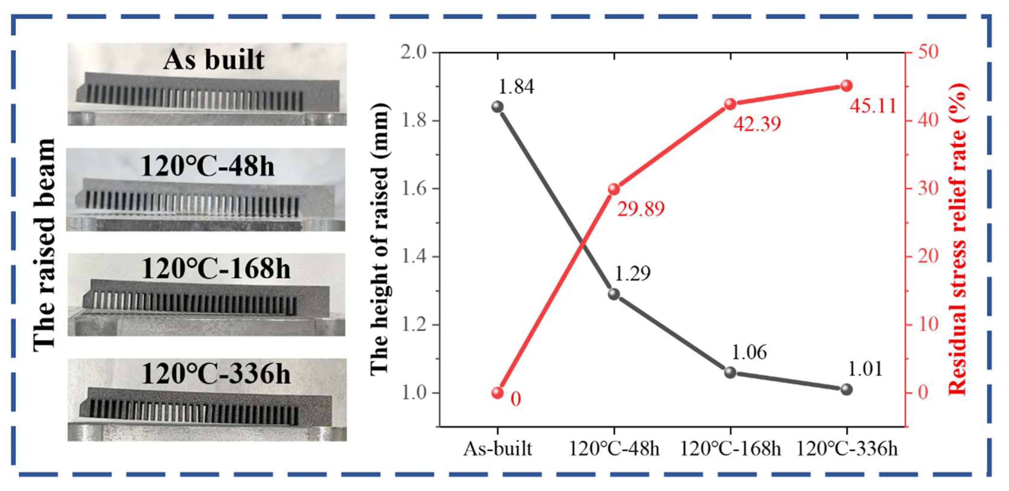
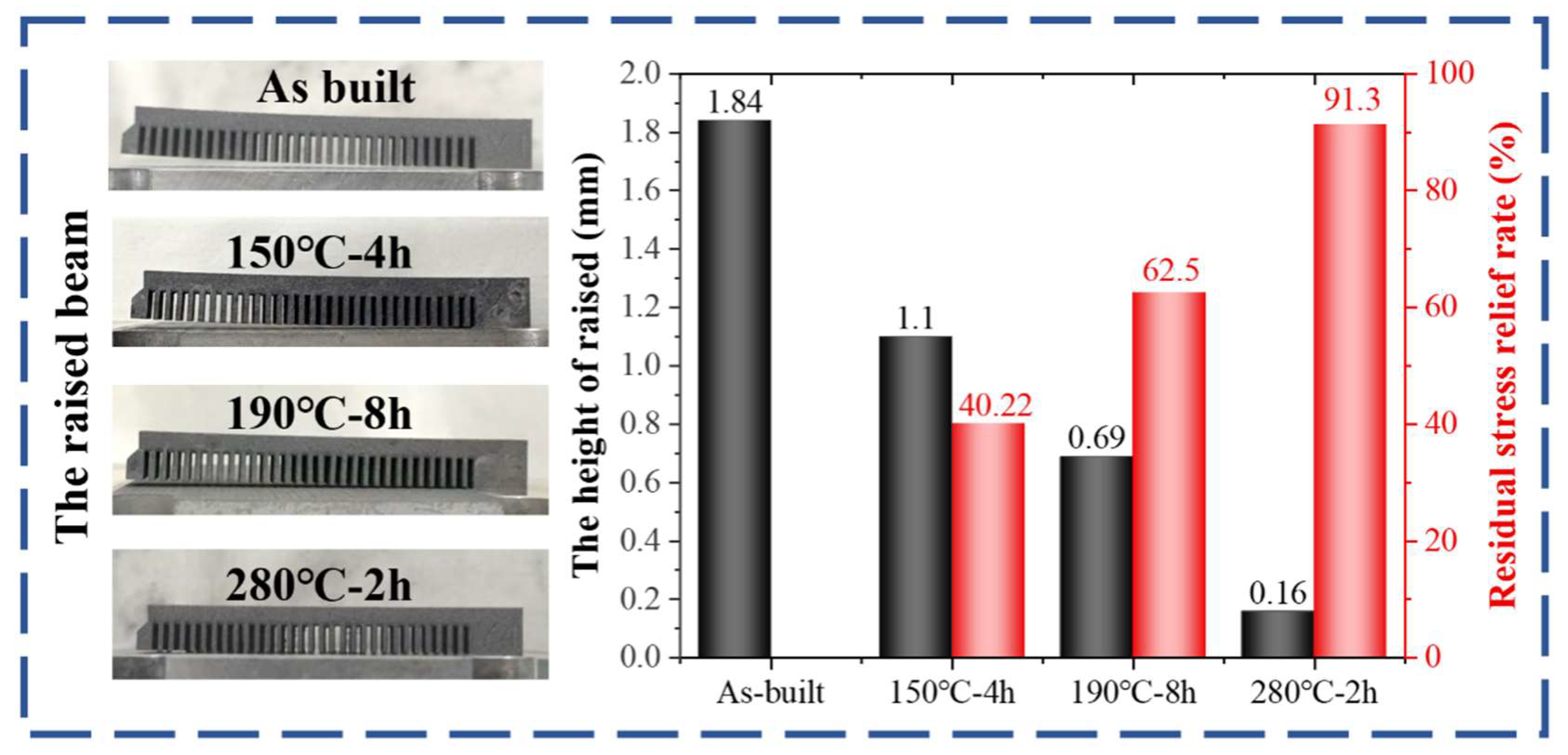
3.1. Effects of Direct Aging on Hardness and Residual Stresses

Figure 2 presents the Vickers hardness evolution of LPBF TiB2/AlSi7Mg subjected to direct aging at 120 °C for durations ranging from 0 to 336 h. As shown, during the initial 0–120 h period, the hardness increases steadily from 131 HV in the AB condition to above 140 HV, corresponding to the under-aging stage of the aging process. Between 120 and 192 h, the hardness remains stable at approximately 143–144 HV, indicating the peak-aging stage. Beyond 192 h, the hardness gradually decreases with prolonged aging time, marking the over-aging stage. To represent these three distinct stages, samples aged at 120 °C for 48 h, 168 h, and 336 h were selected to evaluate the residual stress relief under under-aged, peak-aged, and over-aged conditions, respectively. Notably, while the holding time for the three typical aging characteristics at this temperature is excessively long, it remains scientifically significant. This not only extends the research scope of time as an influencing variable for exploring residual stress relief but also enriches the performance database of multi-point aging treatment for this alloy, offering additional research possibilities and references for other researchers.
Figure 3 illustrates the evolution of residual stress for three selected aging conditions in comparison to the AB state. The quantitative results indicate that the maximum warpage height of the specimens decreased gradually from 1.84 mm in the AB state to 1.01 mm following over-aging for 336 h (with a residual stress relief rate up to 45.11%), demonstrating that low-temperature aging effectively alleviates residual stress. Notably, the difference in stress relief between the peak-aged and over-aged conditions is a mere 2.7%, confirming that once the aging time reaches the peak-aging stage, the rate of stress relaxation significantly diminishes. This suggests that further extension of the aging duration at this temperature progressively diminishes its effectiveness in relieving residual stress, preventing complete stress elimination. This nonlinear stress relaxation behavior is closely related to the synergistic mechanisms of atomic diffusion. Residual stress relief at low temperature mainly relies on the rearrangement by atom diffusion and dislocation motion to homogenize the stress distribution within the material. However, solute atom diffusion is constrained by the relatively low aging temperature, leading to a low diffusion coefficient at 120 °C as described by the Arrhenius equation, and consequently, the overall stress relief efficiency remains below 50%. Sensitivity analysis based on an Arrhenius-type kinetic model reveals that the temperature sensitivity coefficient of residual stress elimination is significantly higher than the time sensitivity coefficient [20]. Therefore, it can be reasonably inferred that, rather than prolonging the aging time, a moderate increase in aging temperature (ΔT = 30–50 °C) constitutes a more effective strategy to further optimize residual stress relief.
Therefore, this study further investigated treatments at 150 °C for 4 h, 190 °C for 8 h, and 280 °C for 2 h to evaluate the efficiency of residual stress relief through elevated temperatures. The results are presented in Figure 4. Compared to extending the aging duration at 120 °C, elevating the aging temperature proves to be a more effective strategy for residual stress reduction. The maximum cantilever beam warpage decreased to 1.1 mm after aging at 150 °C for 4 h, and further reduced to 0.69 mm after aging at 190 °C for 8 h, corresponding to stress relief efficiencies of approximately 40% and 62%, respectively. These findings further support the feasibility and effectiveness of the direct aging strategy for residual stress mitigation. Notably, annealing at 280 °C for 2 h resulted in residual stress reduction of up to 91%, effectively achieving near-complete stress elimination. This further corroborates that the temperature sensitivity coefficient governing residual stress relief is significantly greater than that associated with aging duration. Nevertheless, excessively high temperatures generally degrade overall mechanical properties; therefore, the optimal aging regime should balance residual stress relief with mechanical performance.

3.2. Effects of Direct Aging on Mechanical Properties

Figure 5 presents the engineering stress–strain curves corresponding to all heat treatment conditions, with the associated YS, UTS, and elongation (EL) values summarized in Table 2. When the tensile loading direction is perpendicular to the BD, referred to as the horizontal specimen, the overall mechanical performance is typically better compared to specimens loaded parallel to the BD (vertical specimens). This is evidenced by higher strength and ductility in the horizontal specimens, a phenomenon widely reported in previous studies [5,21]. For the AB condition, the horizontal specimens exhibited YS of 290 MPa, UTS of 475 MPa, and EL of 10.6%, whereas the vertical specimens showed YS of 255 MPa, UTS of 475 MPa, and EL of 9.0%. After DA at 120 °C for varying durations, both orientations showed significant YS improvements of 55–85 MPa (increases of 19%–33%), while UTS increased slightly by ~30 MPa, stabilizing around 505 MPa. Notably, both under-aged and over-aged samples exhibited enhanced strength without a substantial sacrifice in ductility, maintaining EL above 6%, which meets the requirements for aerospace components. However, the elongation of the vertically oriented peak-aged sample dropped below 6%, failing to satisfy application demands. Considering residual stress relief across different aging states, the under-aged condition provides favorable strength–ductility matching but limited stress relief. Although the over-aged condition shows good synergy between strength and stress relief, the prolonged treatment time renders it suboptimal. The 150 °C for 4 h treatment achieves an excellent balance: horizontal specimens exhibited YS, UTS, and EL of 358 MPa, 503 MPa, and 9.2%, respectively, while vertical specimens reached 325 MPa, 510 MPa, and 7.0%, indicating significant strength enhancement along with adequate ductility retention. In contrast, the 190 °C for 8 h treatment results in modest YS improvement and good ductility retention, but UTS slightly decreases, suggesting that precipitates coarsening has reduced work-hardening capacity. Despite nearly complete residual stress elimination under the 280 °C for 2 h annealing treatment, the strength decreased to the level of cast alloys [22], attributed to the degradation of strengthening contributions from the metastable cellular structure formed during rapid solidification [16].
Based on the above findings, the aging treatments at 150 °C for 4 h and 190 °C for 8 h can be identified as optimal DA strategies, offering a favorable balance between enhanced mechanical strength and effective residual stress relief. The outstanding mechanical properties originate from solid solution strengthening, fine grain strengthening, load transfer strengthening, second-phase strengthening and precipitation strengthening [7,8,23,24]. This will be further discussed in Section 3.3 in combination with microstructure. Both conditions involve relatively low aging temperatures and moderate holding times that ensure adequate thermal homogenization throughout the component (typically > 2 h), while avoiding the high energy consumption associated with excessively prolonged treatments (<24 h). These attributes underscore the potential of these regimes for cost-effective and efficient post-processing, thereby demonstrating strong applicability in industrial manufacturing environments.

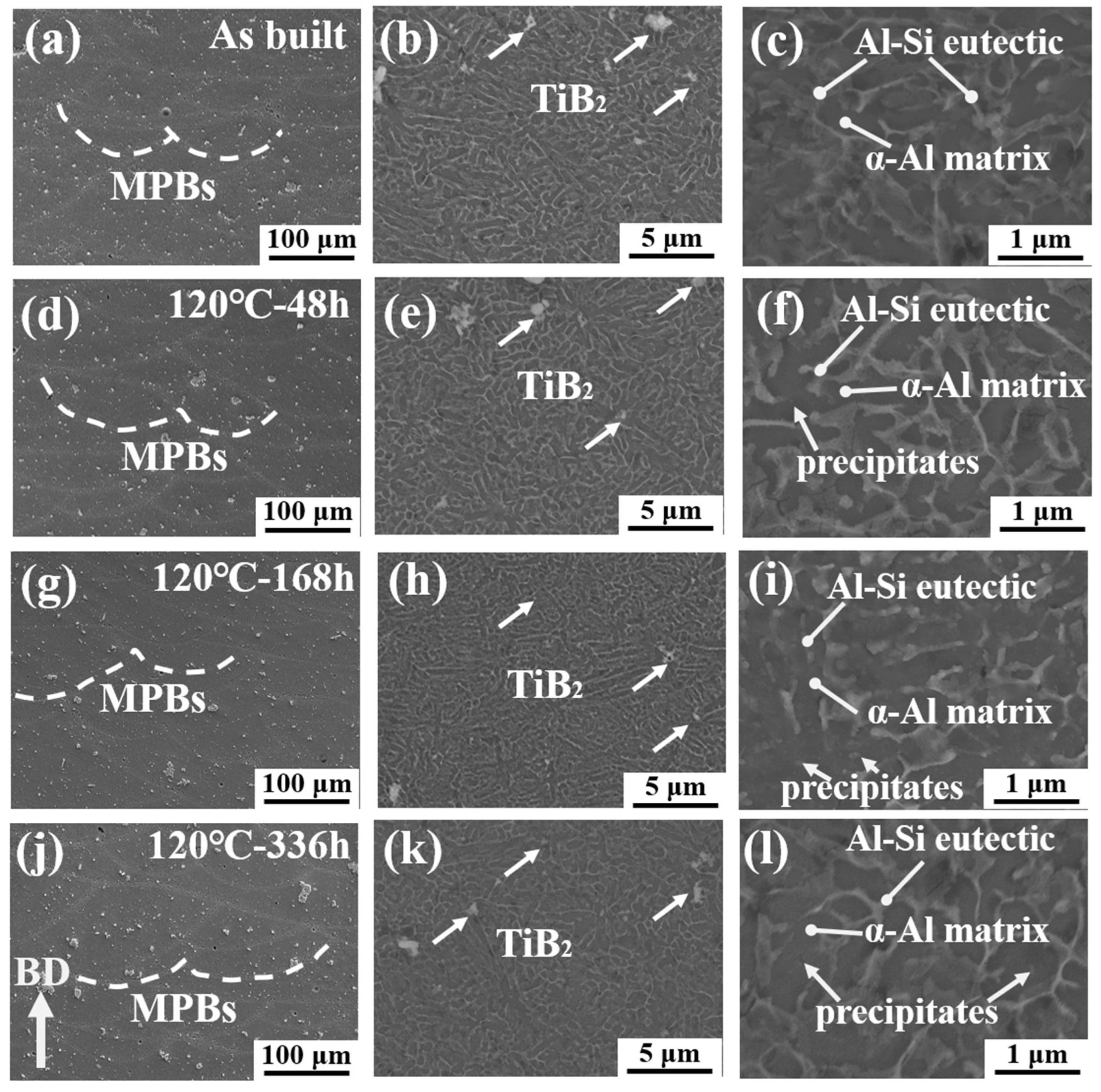
3.3. Effects of Direct Aging on Microstructure

Figure 6 presents the SEM microstructures of the LPBF TiB2/AlSi7Mg composites in the AB condition and after three DA treatments at 120 °C. The observed surfaces are parallel to the BD. In all conditions, melt pool structures formed by the thermal conduction mode are clearly visible, with distinct melt pool boundaries (MPBs) corresponding to the laser scan tracks during the LPBF process. Due to laser remelting, the melt pools in the longitudinal section exhibit a semi-cylindrical overlapping pattern [25,26], with typical dimensions of approximately 100–300 μm in width and 80–120 μm in height. TiB2 particles are uniformly distributed, though slight agglomeration is observed at some cellular boundaries [8]. They act as heterogeneous nucleation sites to promote grain refinement, while acting as a second phase to hinder dislocation motion to strengthen the composites. Therefore, they lead to fine grain strengthening, second phase strengthening, and load-bearing strengthening. The nonequilibrium cellular structure resulting from rapid solidification during LPBF—comprising an Al matrix within the cells and an Al–Si eutectic network at the boundaries, with feature sizes ranging from 0.5 to 1 μm—remains largely unchanged after the aging treatments at 120 °C. However, a small number of nanoscale precipitates are observed within the Al matrix after aging (Figure 6f,i,l). The presence of the cellular structure inhibits dislocation motion, as dislocations cannot easily pass through the Al–Si eutectic network that constitutes the cell boundaries [27]. Therefore, the residual stress relief at this temperature that is dependent on dislocation rearrangement is limited, and the precipitates pinning dislocations preventing their annihilation also limit stress homogenization. This mechanism provides a clear explanation for the limited residual stress relief observed at 120 °C (Figure 3).
Figure 7 further presents the SEM microstructures of the composites after three different thermal treatment strategies: 150 °C for 4 h, 190 °C for 8 h, and 280 °C for 2 h. With increasing temperature, the MPBs become progressively blurred due to microstructural homogenization [28,29]. The two elevated temperature DA treatments do not significantly alter the cellular structure, and a substantial number of nanoscale precipitates are observed within the Al matrix. The relatively smaller strength enhancement observed after the 190 °C for 8 h treatment compared to the 120 °C and 150 °C conditions (Figure 5) may be attributed to the coarsening of precipitates at elevated temperatures, which reduces their effectiveness in impeding dislocation motion. After annealing at 280 °C, the Al–Si eutectic network is completely disrupted (Figure 7h,i), and the cell walls become discontinuous. As a result, dislocation motion is significantly facilitated, which explains the dramatic drop in strength and the substantial increase in ductility in this condition. These observations highlight the significant contribution of the nonequilibrium solidification-induced cellular structure formed during LPBF to the composites’ strengthening. The presence of the cellular structure enhances mechanical properties through both grain boundary strengthening (Hall–Petch effect) and load-bearing strengthening mechanisms [7,8,23,24,30].
Figure 8 presents the EBSD inverse pole figure (IPF) maps and kernel average misorientation (KAM) maps of the AB condition, the two elevated temperature aging conditions, and the annealed condition. As shown in the IPF maps, all samples exhibit random grain orientations without any pronounced texture, which is attributed to the grain growth-inhibited effect of the TiB2 particles [5]. The average grain diameters (davg), as labeled in Figure 8a,c,e,g, show no significant increase in grain size following either aging or annealing treatments. The KAM maps, commonly used as an indirect indicator of residual stress levels in samples [31,32,33], show average KAM values that exhibit a trend consistent with the residual stress evolution observed in previous sections (Figure 4). This strong correlation supports the reliability and effectiveness of the stress relief measurement method employed in this study.
To further investigate the nanostructure of precipitates after aging, a comparative STEM analysis was conducted between the AB sample and the 150 °C for 4 h treated sample (which exhibited the best synergy between mechanical performance and residual stress reduction). The results are shown in Figure 9. In Figure 9a, regions with varying contrast correspond to different grains. The cellular structures are observed to be continuous and uniformly distributed within the grains. The Al–Si eutectic network not only delineates the cell boundaries but also coincides with the grain boundaries, confirming that the cellular structure acts as sub-grains smaller than the primary grains, thereby playing a critical role in Hall–Petch strengthening. A magnified view of a complete cellular structure within Grain 3 in Figure 9a is shown in Figure 9b. In the AB condition, a small number of dislocations are visible within the cells, which are attributed to thermal stresses generated by the steep thermal gradients during the LPBF process. These dislocations contribute to the relatively high residual stress observed in the AB sample. Figure 9c presents the EDS elemental mapping of the same cellular structure. The results confirm the structural integrity of the Al–Si eutectic network. Mg is found to preferentially segregate along the cell walls. Due to B’s low atomic number, weak characteristic X-ray energy, and detector/sample constraints, EDS struggles to detect B effectively. However, TiB2 particles exhibit an extremely high melting point (~3230 °C) and excellent chemical stability (without reacting with Al, Si, or Mg). Therefore, the distribution of TiB2 particles can be characterized by the distribution of Ti elements. TiB2 particles serve as heterogeneous nucleation sites, promoting grain refinement during the LPBF process.
As shown in Figure 9d, no obvious dislocations were observed within the Al matrix after the 150 °C for 4 h treatment, further confirming the effectiveness of this aging strategy in relieving residual stress by reducing dislocation density. Figure 9e reveals a large number of needle-shaped precipitates within the Al matrix, with lengths ranging from 10 to 50 nm and widths of 3 to 5 nm. Figure 9f presents the HRTEM image of these precipitates, confirming that they are pure Si phases with a diamond cubic structure. Fast Fourier transform (FFT) analysis (inset of Figure 9f) indicates that the precipitates and matrix satisfy the orientation relationships of [2,3,4,5,6,7,8,9,10,11] Si//[001] Al and (2–20)Si//(0–20)Al, consistent with previous reports [21,34]. This demonstrates that the excellent strengthening effect in this condition results from the retention of the intact cellular structure combined with the introduction of nanoscale precipitates. The strength increment mainly originates from the nanoscale precipitates. Since their size exceeds the critical size (~5 nm) for cutting and bypass strengthening mechanisms in Al–Si alloys [35], the strengthening is primarily attributed to the Orowan mechanism induced by needle-like Si precipitates. According to Li et al. [8], applying the same model yields a calculated strength increment Δσ ≈ 71 MPa for this condition, which is in good agreement with the tensile test results summarized in Table 2.

3.4. Fracture Topography

Figure 10 presents a comparative analysis of the tensile fracture morphologies of samples in the AB state and three aging conditions at 120 °C—underaged, peak-aged, and overaged—with the tensile direction oriented parallel to the BD. The fracture surfaces for all conditions exhibit a combination of brittle fracture features, such as tearing ridges, and ductile fracture features, such as dimples, confirming that the fracture process is governed by a mixed ductile–brittle mechanism [21,36,37]. The crack propagation tortuosity and dimple size (~500 nm, comparable to the cellular structure size) in the underaged (Figure 10d,e) and overaged (Figure 10j,k) samples are essentially consistent with those observed in the AB state (Figure 10a,b), which correlates well with their similar experimentally observed elongation values. In contrast, the peak-aged sample displays distinctly different fracture characteristics, exhibiting significantly reduced crack propagation tortuosity (Figure 10g,h) and localized regions featuring typical cleavage facets (Figure 10i), indicative of a predominance of brittle fracture mechanisms [38].
Figure 11 presents the SEM fracture morphologies of samples subjected to aging treatments at 150 °C for 4 h, 190 °C for 8 h, and 280 °C for 2 h. All three conditions exhibit fracture behavior governed by a mixed ductile–brittle mechanism. The sample aged at 190 °C for 8 h, which exhibits relatively lower ductility, displays small, smooth cleavage facets on the fracture surface (Figure 11d,f). Notably, although the sample annealed at 280 °C for 2 h demonstrates nearly double the elongation relative to the AB condition (Figure 5c,d), its fracture mechanism remains fundamentally unchanged. The three-dimensional fracture surface morphology of the 280 °C annealed sample becomes markedly more complex, with a more tortuous crack propagation path (Figure 11g,h), demonstrating the improvement in ductility. The formation of dimples primarily originates from interface decohesion between second-phase particles and the matrix, induced by dislocation motion. During plastic deformation, incompatibility in deformation between the Al matrix and TiB2/Si precipitates induces micro-void nucleation around the second-phase particles. With increasing strain, adjacent micro-voids coalesce through shear, forming characteristic dimple structures. The increment of precipitates leads to an increase in crack nucleation sites, thereby reducing material plasticity. This accounts for the differences in plasticity after different aging treatments (Figure 5 and Table 2). Although the dimple size distribution in the 280 °C treated samples is comparable to that of other conditions, enhanced contrast differences at the edges and interior indicate increased dimple depth (Figure 11i), suggesting that high-temperature treatment alters interfacial bonding strength—potentially a key factor contributing to macroscopic ductility enhancement.
Therefore, the fracture behavior of LPBF TiB2/AlSi7Mg composites is consistently governed by a mixed ductile–brittle mechanism. To achieve or maintain enhanced ductility, microstructural regulation aimed at promoting the dominance of ductile deformation mechanism is essential. Selecting optimal aging parameters to optimize precipitate distribution is an effective strategy. These findings provide theoretical guidance for the development of high-strength, high-ductility additively manufactured aluminum alloys.

4. Conclusions

This study systematically investigates direct aging effects on residual stress, mechanical properties, and microstructure in LPBF TiB2/AlSi7Mg composites. The key conclusions are as follows:
  • Stress relief level: Aging temperature dominates residual stress relief more than time. Treatments at 150 °C for 4 h and 190 °C for 8 h reduced stresses by 40% and 62%, respectively, while 120 °C for 336 h achieved 45.1% relief. Although 280 °C showed 91% stress relief, it disrupted the Al–Si eutectic network, compromising strength.
  • Optimal aging conditions: Balancing performance and efficiency, 150 °C for 4 h (YS = 358 MPa, UTS = 503 MPa, EL = 9.2%) emerged as optimal strategy, followed by the 190 °C for 8 h treatment. Low-temperature aging (120 °C) improved strength but required impractical processing times.
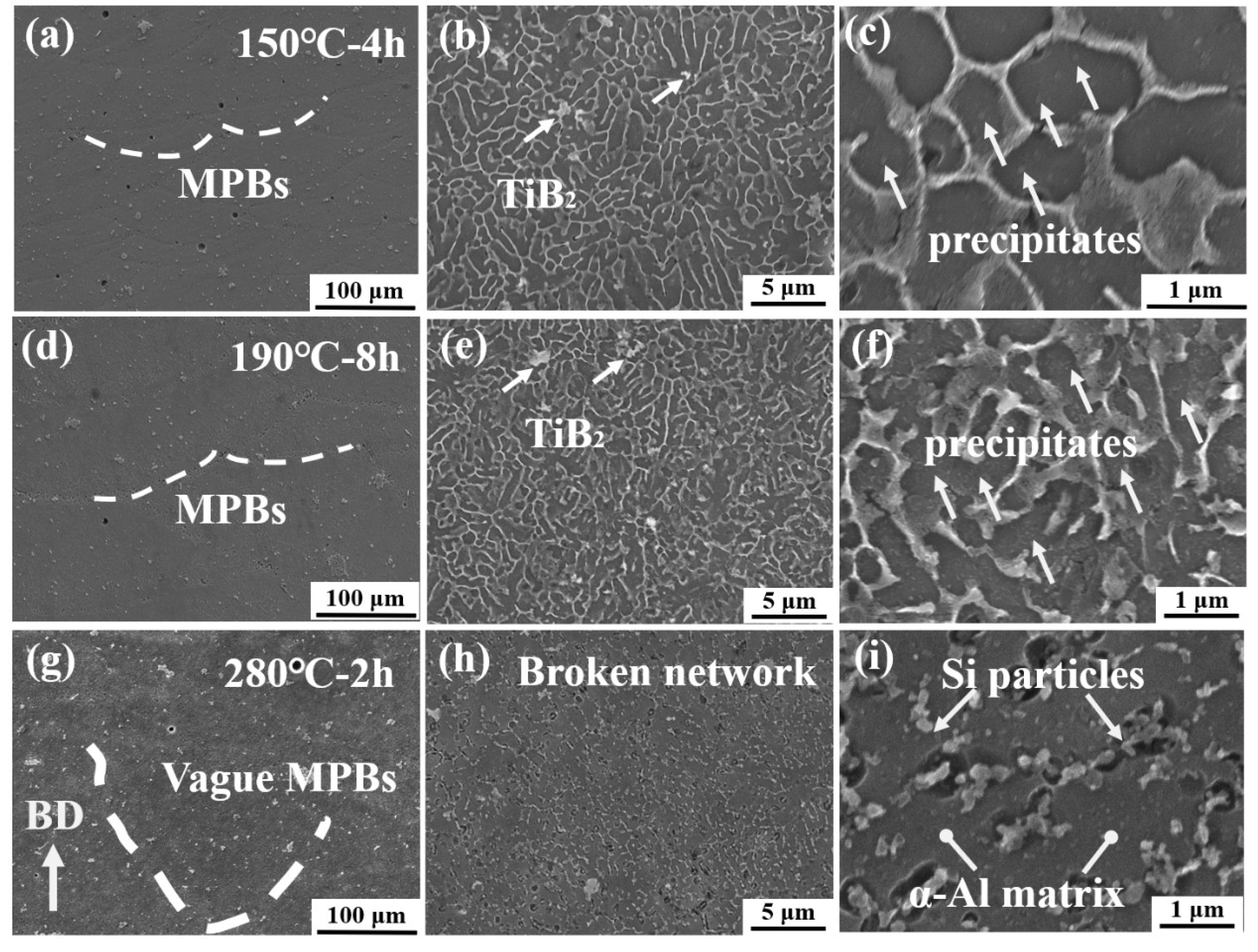
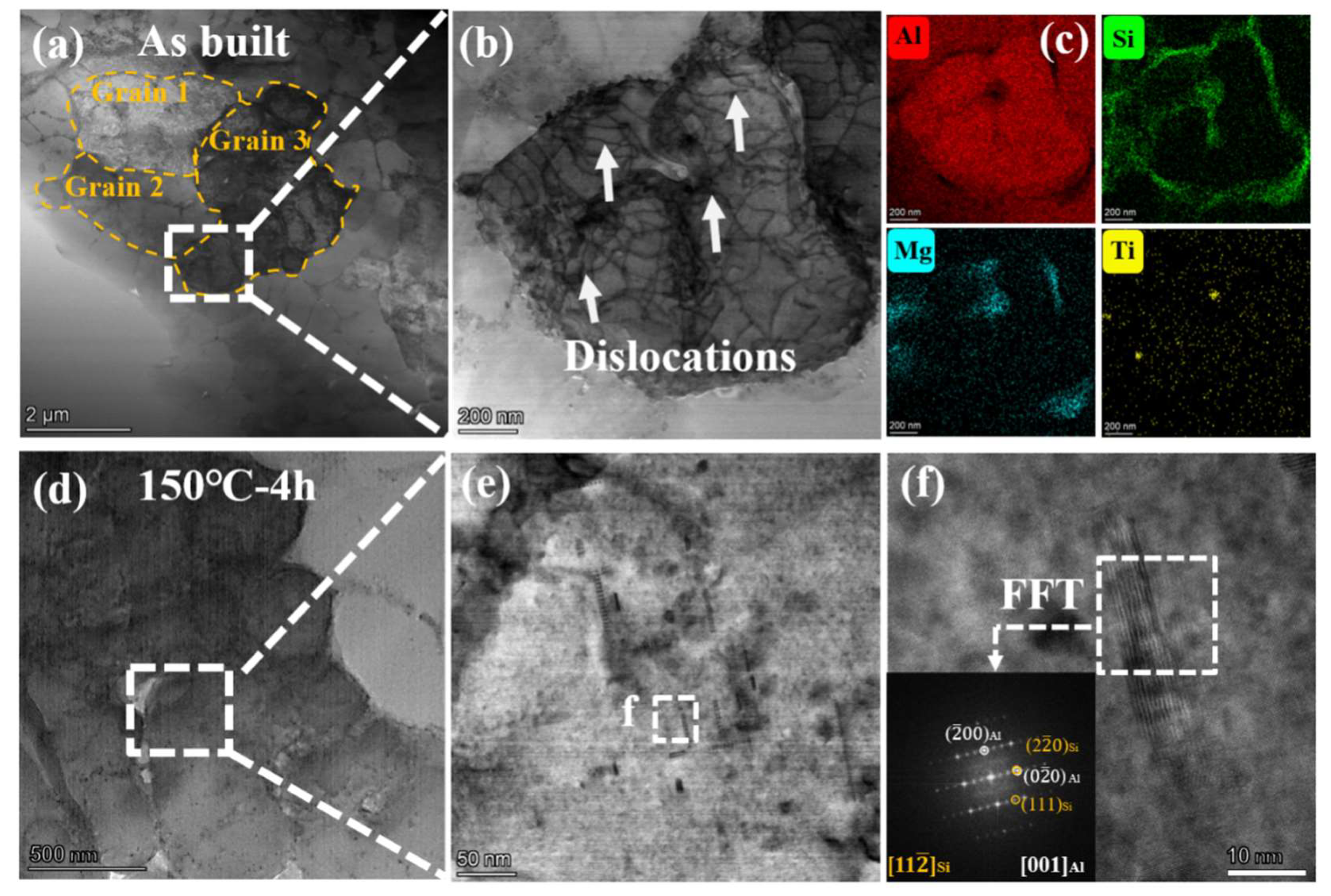
  • Microstructural evolution: As-built samples feature 0.5–1 μm non-equilibrium cellular structures strengthened by the Hall–Petch effect and load-bearing mechanism. Low-temperature aging preserves cellular structures while introducing nanoscale Si precipitates for precipitation strengthening, whereas high-temperature annealing degrades strength by disrupting the cellular network. All aged samples exhibit ductile–brittle mixed fracture.
  • Industrial relevance: The 150 °C for 4 h and 190 °C for 8 h aging regimes offer superior balance of high strength (YS > 300 MPa, UTS > 450 MPa) and significant stress relief (40%–62%) within 8 h, outperforming conventional post-processing methods for cost-effective industrial applications.

Author Contributions

P.R.: Conceptualization, Funding acquisition, Writing—original draft. X.F.: Conceptualization, Funding acquisition, Writing—original draft. Y.C. (Yirui Chang): Data curation, Formal analysis, Investigation, Validation, Writing—review and editing. Y.C. (Yong Chen): Investigation, Supervision. D.H.: Investigation, Supervision. Y.L.: Conceptualization, Supervision, Investigation, Formal analysis, Validation, Writing—review and editing, Supervision, Funding acquisition. All authors have read and agreed to the published version of the manuscript.

Funding

This research was supported by the R&D project of AVIC Chengdu Aircraft Industrial (Group) Co., Ltd. (JY-23-A33-0026), and the Ningbo international science and technology cooperation program (NO. 2023H004).

Institutional Review Board Statement

This study did not require ethical approval.

Informed Consent Statement

This study did not involve humans.

Data Availability Statement

Data will be made available on request.

Conflicts of Interest

Authors Peng Rong, Xin Fang, Yong Chen and Dan Huang were employed by the company AVIC Chengdu Aircraft Industrial (Group) Co., Ltd. The remaining authors declare that the research was conducted in the absence of any commercial or financial relationships that could be construed as a potential conflict of interest.

References

  1. Gu, D.; Shi, X.; Poprawe, R.; Bourell, D.L.; Setchi, R.; Zhu, J. Material-structure-performance integrated laser-metal additive manufacturing. Science 2021, 372, abg1487. [Google Scholar] [CrossRef] [PubMed]
  2. Zhao, L.; Song, L.B.; Macias, J.G.S.; Zhu, Y.X.; Huang, M.S.; Simar, A.; Li, Z.H. Review on the correlation between microstructure and mechanical performance for laser powder bed fusion AlSi10Mg. Addit. Manuf. 2022, 56, 102914. [Google Scholar] [CrossRef]
  3. Rometsch, P.A.; Zhu, Y.M.; Wu, X.H.; Huang, A.J. Review of high-strength aluminium alloys for additive manufacturing by laser powder bed fusion. Mater. Des. 2022, 219, 110779. [Google Scholar] [CrossRef]
  4. Li, Y.; Wang, Y.H.; Hu, L.; Chen, T.T.; Ji, G.; Chen, H.; Wang, H.Z.; Wang, H.W.; Chen, Z. Nanoscale engineering of low-misfit TiB2/Al3(Sc,Zr)/α-Al multi-interface to improve strength-ductility synergy for direct energy deposited aluminum alloy. Addit. Manuf. 2024, 79, 103913. [Google Scholar] [CrossRef]
  5. Xiao, Y.K.; Bian, Z.Y.; Wu, Y.; Ji, G.; Li, Y.Q.; Li, M.J.; Lian, Q.; Chen, Z.; Addad, A.; Wang, H.W. Effect of nano-TiB2 particles on the anisotropy in an AlSi10Mg alloy processed by selective laser melting. J. Alloys Compd. 2019, 798, 644–655. [Google Scholar] [CrossRef]
  6. Xiao, Y.K.; Chen, H.; Bian, Z.Y.; Sun, T.T.; Ding, H.; Yang, Q.; Wu, Y.; Lian, Q.; Chen, Z.; Wang, H.W. Enhancing strength and ductility of AlSi10Mg fabricated by selective laser melting by TiB2 nanoparticles. J. Mater. Sci. Technol. 2022, 109, 254–266. [Google Scholar] [CrossRef]
  7. Dan, C.Y.; Cui, Y.C.; Wu, Y.; Chen, Z.; Liu, H.; Ji, G.; Xiao, Y.K.; Chen, H.; Wang, M.L.; Liu, J.; et al. Achieving ultrahigh fatigue resistance in AlSi10Mg alloy by additive manufacturing. Nat. Mater. 2023, 22, 1182–1188. [Google Scholar] [CrossRef]
  8. Li, X.P.; Ji, G.; Chen, Z.; Addad, A.; Wu, Y.; Wang, H.W.; Vleugels, J.; Van Humbeeck, J.; Kruth, J.P. Selective laser melting of nano-TiB2 decorated AlSi10Mg alloy with high fracture strength and ductility. Acta Mater. 2017, 129, 183–193. [Google Scholar] [CrossRef]
  9. Li, S.S.; Yue, X.; Li, Q.Y.; Peng, H.L.; Dong, B.X.; Liu, T.S.; Yang, H.Y.; Fan, J.; Shu, S.L.; Qiu, F.; et al. Development and applications of aluminum alloys for aerospace industry. J. Mater. Res. Technol. 2023, 27, 944–983. [Google Scholar] [CrossRef]
  10. Salmi, A.; Atzeni, E.; Iuliano, L.; Galati, M. Experimental analysis of residual stresses on AlSi10Mg parts produced by means of Selective Laser Melting (SLM). In Proceedings of the 10th CIRP Conference on Intelligent Computation in Manufacturing Engineering—CIRP ICME ‘16, Ischia, Italy, 20–22 July 2016; Volume 62, pp. 452–457. [Google Scholar] [CrossRef]
  11. Dai, K.; Shaw, L. Thermal and stress modeling of multi-material laser processing. Acta Mater. 2001, 49, 4171–4181. [Google Scholar] [CrossRef]
  12. Marola, S.; Bosia, S.; Veltro, A.; Fiore, G.; Manfredi, D.; Lombardi, M.; Amato, G.; Baricco, M.; Battezzati, L. Residual stresses in additively manufactured AlSi10Mg Raman spectroscopy and X-ray diffraction analysis. Mater. Des. 2021, 202, 109550. [Google Scholar] [CrossRef]
  13. Bagherifard, S.; Beretta, N.; Monti, S.; Riccio, M.; Bandini, M.; Guagliano, M. On the fatigue strength enhancement of additive manufactured AlSi10Mg parts by mechanical and thermal post-processing. Mater. Des. 2018, 145, 28–41. [Google Scholar] [CrossRef]
  14. Buchbinder, D.; Meiners, W.; Pirch, N.; Wissenbach, K.; Schrage, J. Investigation on reducing distortion by preheating during manufacture of aluminum components using selective laser melting. J. Laser Appl. 2014, 26, 012004. [Google Scholar] [CrossRef]
  15. Zhang, X.C.; Kang, J.W.; Rong, Y.M.; Wu, P.Y.; Feng, T. Effect of Scanning Routes on the Stress and Deformation of Overhang Structures Fabricated by SLM. Materials 2019, 12, 47. [Google Scholar] [CrossRef] [PubMed]
  16. Wang, M.; Song, B.; Wei, Q.S.; Zhang, Y.J.; Shi, Y.S. Effects of annealing on the microstructure and mechanical properties of selective laser melted AlSi7Mg alloy. Mater. Sci. Eng. A-Struct. Mater. Prop. Microstruct. Process. 2019, 739, 463–472. [Google Scholar] [CrossRef]
  17. Di Egidio, G.; Ceschini, L.; Morri, A.; Martini, C.; Merlin, M. A Novel T6 Rapid Heat Treatment for AlSi10Mg Alloy Produced by Laser-Based Powder Bed Fusion: Comparison with T5 and Conventional T6 Heat Treatments. Metall. Mater. Trans. B 2022, 53, 284–303. [Google Scholar] [CrossRef]
  18. Chen, Z.; Sun, G.A.; Wu, Y.; Mathon, M.H.; Borbely, A.; Chen, D.; Ji, G.; Wang, M.L.; Zhong, S.Y.; Wang, H.W. Multi-scale study of microstructure evolution in hot extruded nano-sized TiB2 particle reinforced aluminum composites. Mater. Des. 2017, 116, 577–590. [Google Scholar] [CrossRef]
  19. Hovig, E.W.; Azar, A.S.; Mhamdi, M.; Sorby, K. Mechanical Properties of AlSi10Mg Processed by Laser Powder Bed Fusion at Elevated Temperature. In Tms 2020 149th Annual Meeting & Exhibition Supplemental Proceedings; Springer International Publishing: Berlin/Heidelberg, Germany, 2020; pp. 395–404. [Google Scholar] [CrossRef]
  20. Batiot, B.; Rogaume, T.; Richard, F.; Luche, J.; Collin, A.; Guillaume, E.; Torero, J.L. Origin and Justification of the Use of the Arrhenius Relation to Represent the Reaction Rate of the Thermal Decomposition of a Solid. Appl. Sci. 2021, 11, 4075. [Google Scholar] [CrossRef]
  21. Tang, H.; Gao, C.; Zhang, Y.; Zhang, N.; Lei, C.; Bi, Y.; Tang, P.; Rao, J.H. Effects of direct aging treatment on microstructure, mechanical properties and residual stress of selective laser melted AlSi10Mg alloy. J. Mater. Sci. Technol. 2023, 139, 198–209. [Google Scholar] [CrossRef]
  22. Girelli, L.; Tocci, M.; Gelfi, M.; Pola, A. Study of heat treatment parameters for additively manufactured AlSi10Mg in comparison with corresponding cast alloy. Mater. Sci. Eng. A-Struct. Mater. Prop. Microstruct. Process. 2019, 739, 317–328. [Google Scholar] [CrossRef]
  23. Li, Z.; Li, Z.Q.; Tan, Z.Q.; Xiong, D.B.; Guo, Q. Stress relaxation and the cellular structure-dependence of plastic deformation in additively manufactured AlSi10Mg alloys. Int. J. Plast. 2020, 127, 102640. [Google Scholar] [CrossRef]
  24. Li, C.; Zhang, W.X.; Yang, H.O.; Wan, J.; Huang, X.X.; Chen, Y.Z. Microstructural origin of high strength and high strain hardening capability of a laser powder b e d fuse d AlSi10Mg alloy. J. Mater. Sci. Technol. 2024, 197, 194–206. [Google Scholar] [CrossRef]
  25. Takata, N.; Kodaira, H.; Sekizawa, K.; Suzuki, A.; Kobashi, M. Change in microstructure of selectively laser melted AlSi10Mg alloy with heat treatments. Mater. Sci. Eng. A-Struct. Mater. Prop. Microstruct. Process. 2017, 704, 218–228. [Google Scholar] [CrossRef]
  26. Thijs, L.; Kempen, K.; Kruth, J.P.; Van Humbeeck, J. Fine-structured aluminium products with controllable texture by selective laser melting of pre-alloyed AlSi10Mg powder. Acta Mater. 2013, 61, 1809–1819. [Google Scholar] [CrossRef]
  27. Wu, J.; Wang, X.Q.; Wang, W.; Attallah, M.M.; Loretto, M.H. Microstructure and strength of selectively laser melted AlSi10Mg. Acta Mater. 2016, 117, 311–320. [Google Scholar] [CrossRef]
  28. Medrano, V.A.; Arrieta, E.; Merino, J.; Ruvalcaba, B.; Caballero, K.; Ramirez, B.; Diemann, J.; Murr, L.E.; Wicker, R.B.; Godfrey, D.; et al. A comprehensive and comparative study of microstructure and mechanical properties for post-process heat treatment of AlSi7Mg alloy components fabricated in different laser powder bed fusion systems. J. Mater. Res. Technol. 2023, 24, 6820–6842. [Google Scholar] [CrossRef]
  29. Ming, X.; Song, D.; Yu, A.; Tan, H.; Zhang, Q.; Zhang, Z.; Chen, J.; Lin, X. Effect of heat treatment on microstructure, mechanical and thermal properties of selective laser melted AlSi7Mg alloy. J. Alloys Compd. 2023, 945, 169278. [Google Scholar] [CrossRef]
  30. Gonela, K.K.; Vijayavarman, C.; Palanivel, M.; Mariappan, L.; Ramasubramanian, L.N.; Kannan, A.R. Effect of robotic weaving motion on mechanical and microstructural characteristics of wire arc additively manufactured NiTi shape memory alloy. Int. J. Mater. Res. Technol. 2023, 114, 947–954. [Google Scholar] [CrossRef]
  31. Motz, C.; Schöberl, T.; Pippan, R. Mechanical properties of micro-sized copper bending beams machined by the focused ion beam technique. Acta Mater. 2005, 53, 4269–4279. [Google Scholar] [CrossRef]
  32. Ramazani, A.; Mukherjee, K.; Schwedt, A.; Goravanchi, P.; Prahl, U.; Bleck, W. Quantification of the effect of transformation-induced geometrically necessary dislocations on the flow-curve modelling of dual-phase steels. Int. J. Plast. 2013, 43, 128–152. [Google Scholar] [CrossRef]
  33. Calcagnotto, M.; Ponge, D.; Demir, E.; Raabe, D. Orientation gradients and geometrically necessary dislocations in ultrafine grained dual-phase steels studied by 2D and 3D EBSD. Mater. Sci. Eng. A Struct. Mater. Prop. Microstruct. Process. 2010, 527, 2738–2746. [Google Scholar] [CrossRef]
  34. Xiao, Y.K.; Bian, Z.Y.; Wu, Y.; Ji, G.; Lian, Q.; Wang, H.Z.; Chen, Z.; Wang, H.W. Simultaneously minimizing residual stress and enhancing strength of selective laser melted nano-TiB2 decorated Al alloy via post-uphill quenching and ageing. Mater. Charact. 2021, 178, 111242. [Google Scholar] [CrossRef]
  35. Ahn, S.Y.; Moon, J.; Choi, Y.T.; Kim, E.S.; Jeong, S.G.; Park, J.M.; Kang, M.; Joo, H.; Kim, H.S. A precipitation-hardened AlSi10Mg alloy fabricated using selective laser melting. Mater. Sci. Eng. A Struct. Mater. Prop. Microstruct. Process. 2022, 844, 143164. [Google Scholar] [CrossRef]
  36. Zhu, H.; Sun, J.; Guo, Y.; Xu, X.; Huang, Y.; Jiang, Z.; Wu, G.; Li, J.; Liu, W. Effects of post heat treatment on the microstructure and mechanical properties of selective laser melted AlSi10Mg alloys. Mater. Sci. Eng. A Struct. Mater. Prop. Microstruct. Process. 2024, 894, 146195. [Google Scholar] [CrossRef]
  37. Zhao, B.B.; Ye, B.; Wang, L.Y.; Bai, Y.; Yu, X.; Wang, Q.G.; Yang, W.Y. Effect of ageing and thermal exposure on microstructure and mechanical properties of a HPDC Al-Si-Cu-Mg alloy. Mater. Sci. Eng. A Struct. Mater. Prop. Microstruct. Process. 2022, 849, 143463. [Google Scholar] [CrossRef]
  38. Mei, J.; Han, Y.; Sun, J.; Jiang, M.; Zu, G.; Song, X.; Zhu, W.; Ran, X. Improving the comprehensive mechanical property of the AlSi10Mg alloy via parameter adaptation of selective laser melting and heat treatment. J. Alloys Compd. 2024, 981, 173623. [Google Scholar] [CrossRef]
Figure 1. (a) Schematic illustration of samples fabricated via LPBF; (b) Three-dimensional reconstruction of internal pores within a LPBF specimen; (c) Statistical distribution of pore sizes.
Coatings 15 00780 g001
Figure 2. Aging hardening curves for TiB2/AlSi7Mg composites at 120 °C.
Coatings 15 00780 g002
Figure 3. Visualization of cantilever beam warpage at 120 °C and the corresponding variation in residual stress relief rate.
Coatings 15 00780 g003
Figure 4. Visualization of cantilever beam warpage and corresponding residual stress relief under different heat treatment strategies.
Coatings 15 00780 g004
Figure 5. Engineering tensile stress-strain curves for different states under different tensile direction: (a) The tensile curves for the AB and 120 °C aging states when the tensile direction is perpendicular to BD; (b) The tensile curves for the AB and 120 °C aging states when the tensile direction is parallel to BD; (c) The tensile curves for the AB and different states when the tensile direction is perpendicular to BD; (d) The tensile curves for the AB and different states when the tensile direction is parallel to BD.
Coatings 15 00780 g005
Figure 6. SEM images of the composites under (ac) AB, (df) 120 °C-48 h, (gi) 120 °C-168 h, and (jl) 120 °C-336 h states.
Coatings 15 00780 g006
Figure 7. SEM images of the composites under (ac) 150 °C-4 h, (df) 190 °C-8 h, and (gi) 280 °C-2 h states.
Coatings 15 00780 g007
Figure 8. EBSD inverse pole figure (IPF) maps and kernel average misorientation (KAM) maps of the composites under (a,b) AB, (c,d) 150 °C-4 h, (e,f) 190 °C-8 h, and (g,h) 280 °C-2 h states: (a,c,e,g) IPF maps, (b,d,f,h) KAM maps.
Coatings 15 00780 g008
Figure 9. STEM images of the sample along the Al [001] direction, (a,b) AB state BF images, (c) corresponding EDS maps of (b), (d,e) 150 °C-4 h state BF images, (f) HRTEM image of the white box in (e); the inset is the FFT pattern corresponding to the white box region.
Coatings 15 00780 g009
Figure 10. SEM fracture morphology of the composites under (ac) AB, (df) 120 °C-48 h, (gi) 120 °C-168 h, and (jl) 120 °C-336 h states.
Coatings 15 00780 g010
Figure 11. SEM fracture morphology of the composites under (ac) 150 °C-4 h, (df) 190 °C-8 h, and (gi) 280 °C-2 h.
Coatings 15 00780 g011
Table 1. Chemical compositions of TiB2/AlSi7Mg composites determined by ICP-AES (wt%).
ElementSiMgTiBAl
Powders7.001.351.320.62Balance
LPBF7.001.241.290.60Balance
Table 2. Mechanical properties of TiB2/AlSi7Mg composites under different conditions.
ConditionTensile DirectionYS (MPa)UTS (MPa)EL (%)
As-built⊥BD290 ± 5475 ± 610.6 ± 1.2
As-built//BD255 ± 3475 ± 69.0 ± 0.9
120 °C-48 h⊥BD345 ± 2502 ± 110.0 ± 1.5
120 °C-48 h//BD318 ± 5509 ± 16.5 ± 1.1
120 °C-168 h⊥BD356 ± 3509 ± 28.0 ± 0.5
120 °C-168 h//BD330 ± 8515 ± 55.3 ± 0.6
120 °C-336 h⊥BD361 ± 3505 ± 38.5 ± 1.0
120 °C-336 h//BD340 ± 7513 ± 66.1 ± 0.3
150 °C-4 h⊥BD358 ± 5503 ± 39.2 ± 0.3
150 °C-4 h//BD325 ± 2510 ± 27.0 ± 0.4
190 °C-8 h⊥BD320 ± 3457 ± 57.9 ± 0.3
190 °C-8 h//BD300 ± 5459 ± 87.6 ± 0.5
280 °C-2 h⊥BD183 ± 5285 ± 321.3 ± 0.8
280 °C-2 h//BD176 ± 4282 ± 318.3 ± 1
Disclaimer/Publisher’s Note: The statements, opinions and data contained in all publications are solely those of the individual author(s) and contributor(s) and not of MDPI and/or the editor(s). MDPI and/or the editor(s) disclaim responsibility for any injury to people or property resulting from any ideas, methods, instructions or products referred to in the content.

