Article

Pulsed Current Electrodeposition of Gold–Copper Alloys Using a Low-Cyanide Electrolyte

1
Department of Materials Science and Physical Chemistry, Institut de Química Teòrica i Computacional (IQTCUB), Faculty of Chemistry, University of Barcelona, Martí i Franquès Street, 1, 08028 Barcelona, Spain
2
Plating Decor Services & Management, S.L. Industria Street, 16, El Pla Ind. State, 08980 Sant Feliu de Llobregat, Spain
*
Author to whom correspondence should be addressed.
Coatings 2025, 15(7), 778; https://doi.org/10.3390/coatings15070778
Submission received: 28 May 2025 / Revised: 23 June 2025 / Accepted: 27 June 2025 / Published: 30 June 2025

Abstract

The development of stable, non-toxic electrolytes is essential for electrodepositing large-area coatings. This study presents a novel low-cyanide electrolyte, offering a viable alternative to traditional cyanide-based solutions for the electroplating of gold–copper alloys. Compared to conventional baths, the new formulation offers safer handling and environmental compatibility without compromising performance. Electrolyte compositions were optimized via cyclic voltammetry, and coatings were deposited using direct current, pulse current, and reverse pulse current methods. The novel low-cyanide electrolyte system achieved a 99.1% reduction in cyanide use compared with the commercial formulation. Coatings produced with pulse current and reverse pulse current deposition exhibited structural, morphological, and mechanical properties comparable to those obtained from cyanide-based electrolytes. Overall, the low-cyanide electrolyte represents a safer, high-performance alternative to traditional cyanide-based systems.

1. Introduction

Electrodeposited gold–copper (Au–Cu) alloy coatings are widely used in decorative, electronic, and microelectronic applications due to their desirable balance between mechanical performance, corrosion resistance, and gold content reduction [1]. Compared to pure gold coatings, Au–Cu layers offer increased hardness and durability, making them suitable for high-wear environments such as electrical contacts or connector surfaces [2]. Their properties can be finely tuned by controlling the alloy composition and deposition parameters, which makes electrodeposition a preferred method for their fabrication.
A key factor in achieving high-quality decorative Au–Cu coatings lies in the careful control of electrolyte composition and stability during electrodeposition [1,3]. Complexing agents play a crucial role in maintaining ions in solution and modulating their reduction potential [4,5]. The selection of appropriate agents for the metals being deposited can enhance the deposition process, extend the lifespan of the electrolyte, and modify coating properties such as morphology, structure, and mechanical strength [6]. In the context of gold electrodeposition, the stability of complexes is of paramount importance as it impacts ion distribution within the electrolyte and the deposition process.
Historically, cyanide has been employed as a complexing agent for gold, copper, and silver since the mid-19th century [7], and it remains the most effective stabilizer for metallic electrolytes [1]. As illustrated in Table 1, the Au–CN complex exhibits a high formation constant, indicative of its robust stability [8,9]. Notably, over 90% of commercial gold coatings for decorative purposes utilize cyanide, with 18-karat (kt) AuCuIn (or 75% Au) being the most commonly used alloy [10,11].
Despite its efficacy, CN presents significant drawbacks, including its high toxicity to both humans and the environment [16,17]. At pH levels below 8.2, some CN ions convert to HCN, a gaseous form that can volatilize, thereby increasing the risk of poisoning. The use of CN also entails challenges related to safety, waste management, and water treatment [18,19]. In other industrial applications, cyanides face limitations. Free CN ions are incompatible with the production of positive photoresists used in printed circuit patterns, as they can resist peeling and gold deposition beneath, thereby compromising the quality of electronic coatings [20]. Consequently, research is focused on identifying safer and more environmentally benign alternatives for gold electrodeposition [21].
Sulfite-based electrolytes have emerged as the primary alternative to cyanide-based systems due to their reduced environmental impact [18]. However, sulfites present challenges, such as the decomposition of Au(I) to Au(III) and Au0, owing to the limited stability of the gold(I)–sulfite complex [16,22]. Osaka et al. [23] proposed a combination of sulfite and thiosulfate for soft gold coatings, which is stable and effective in near-neutral pH conditions, making it suitable for precise and durable applications. Hitachi et al. [24] developed a thiourea-based electrolyte, akin to those used for other metals. The Institute of Mining and Metallurgy Bor [25,26] has developed mercaptotriazole-based electrolytes for hard coatings, representing the only viable option for decorative coatings without cyanide. Gold chloride-based electrolytes have been less extensively studied but present issues such as chloride ions causing electrolyte instability and gold precipitation. None of the cyanide-free alternatives exhibit sufficient longevity for industrial application, as they all eventually lead to the formation of some gold compounds. The mercaptotriazole-based option has a lifespan of approximately three months, half of the duration for cyanide-based systems. There are even more limited options for alloy electrodeposition [27]. Rapson et al. [28] reported a method for Au–Sn alloys, and other electrolytes have also been proposed for the deposition of Au–Cu alloys using alternative complexing agents to cyanide [2,29]. However, none of these have been tested for decorative applications, which still rely on cyanide-based baths.
Citrates represent a promising alternative due to their ability to maintain bath stability and their lower toxicity [30,31]. They aid in stabilizing metal complexes, particularly copper, and in controlling pH, which is critical for electrodeposition. Sodium citrate can also enhance bath brightness and smoothness, eliminating the need for additional additives [32,33]. This renders it advantageous for depositing metals and alloys such as Cu–Ni [34] and more complex systems like Zn–Mn–Mo and Co–Mo–Re [35]. However, the use of citrate can be challenging, as it may form insoluble complexes that compromise bath stability and coating quality [36]. Sodium citrate is also used in making Au NPs and colloidal dispersions, helping control particle size and dispersion for applications in electronics and biomedicine [34].
In electrodeposition, numerous commercial formulations use citrate for depositing decorative pure gold [37]. However, citrate solutions have not yet been applied to Au–Cu alloy deposition. This study aimed to develop a low-cyanide solution, utilizing citrate as the primary complexing agent, for the electrodeposition of 18-kt AuCu alloy—the most used composition—as an alternative to conventional cyanide-based baths.

2. Materials and Methods

2.1. Electrochemical Setup

All electrochemical measurements were carried out using a VMP2® potentiostat (Princeton Applied Research, Oak Ridge, TN, USA) controlled by EC-Lab® v. 11.50 software. The temperature was controlled using a PolyScience® (Singapore) recirculating thermostat connected to a jacketed electrochemical cell placed on a Bibby HC502 (Bibby Scientific, Stone, UK) magnetic stirring hotplate.

2.2. Cyclic Voltammetry Measurements

Cyclic voltammetries (CVs) were conducted in a 50 mL three-neck glass cell under an inert argon atmosphere. Electrolytic solutions were prepared by dissolving 0.139–0.432 g of potassium dicyanoaurate (K[Au(CN)2], [Au] = 0.01–0.03 M, 99.9%, Plating Decor Services & Management, S.L.®, Sant Feliu de Llobregat, Spain), 0.078–0.239 g of copper (II) sulfate (CuSO4, [Cu] = 0.01–0.03 M, 99%, Merck®, Darmstadt, Germany), and 1.29–3.87 g of sodium citrate ([C6H5O73−] = 0.1–0.3 M, 98.5%, Thermo Scientific®, Waltham, MA, USA), under magnetic stirring at room temperature. The pH of the solution was adjusted to 6.1. A graphite electrode with a basal area of 0.28 cm2 was used as the working electrode, with a platinum filament counter electrode and a 3.5 M Ag/AgCl reference electrode. During measurements, the working electrode was stirred at 100 rpm, and a scan rate of 50 mV·s−1 was applied.

2.3. Preparation of Electrolytes

Electrodeposition solutions were prepared in 200 mL jacketed Pyrex® (Corning Inc., Corning, NY, USA) beakers at room temperature under constant magnetic stirring. For low-cyanide electrolytes, the components were added in the following order: 15.5 g of sodium citrate (0.3 M), 0.60–0.95 g of CuSO4 ([Cu] = 0.019–0.03 M), and 0.56–1.73 g of K[Au(CN)2] ([Au] = 0.01–0.03 M). When required, the pH was adjusted by the dropwise addition of concentrated KOH solution (>99.98%, Thermo Scientific).
The cyanide-based electrolyte was prepared by sequentially adding 15.49 g of CuCN ([Cu] = 0.86 M), 30.73 g of KCN (2.36 M), and 1.44 g of K[Au(CN)2] ([Au] = 0.025 M).
To compare the properties of the AuCu alloys developed in this study, additional AuCuIn alloys were obtained using the commercial cyanide-based electrolyte OMEGAL 180 CdF [10] which is widely used in the industry. Among the commercially available formulations, it exhibits the closest composition to the electrolytes proposed herein.

2.4. Electrodeposition Procedure

Electrodeposition was performed on α-Fe substrate (Ossian® Hull cell panels, Ossian Lagerqvist AB, Järfälla, Sweden), selected to facilitate the analysis of the coating composition, which will be detailed in the characterization section. The panels were cut to dimensions of 3 × 1.5 cm, yielding a deposition area of 4.5 cm2. Prior to deposition, the zinc protective layer was removed by immersion in concentrated HCl, followed by thorough rinsing with Milli-Q® water (Millipore, Burlington, MA, USA). A cylindrical iridium oxide mesh was used as the counter electrode, and a saturated calomel electrode (SCE) was used as the reference.
Electrodeposition with low-cyanide electrolytes was performed at 65 °C, while cyanide-based electrolytes were used at 70 °C. Direct current (DC), pulse current (PC), and reverse pulse current (RPC) deposition modes were applied, following parameters reported in the literature [38], including current density (j), cathodic current density (jC), anodic current density (jA), cathodic time (tC), anodic time (tA), and duty cycle (θ). In the case of PC and RPC, the parameters used are summarized in Table 2. For each set of synthesis conditions, a fixed total charge of 4 C·cm−2 was applied.

2.5. Coating Characterization

The morphology of the electrodeposited coatings was analyzed using a JEOL 7100® field emission scanning electron microscopy (FESEM) system (JEOL, Tokyo, Japan). The elemental composition was assessed by Fischerscope X-Ray® X-ray fluorescence (XRF) equipment (Helmut Fischer GmbH, Sindelfingen, Germany) and confirmed via energy-dispersive X-ray spectroscopy (EDX) integrated into the FESEM system. For the compositional analysis, it was necessary to use an α-Fe substrate, due to its markedly different nature compared to the Au-based coatings obtained. The cross-sectioned samples were cold-mounted and polished using a Struers® polisher (Struers A/S, Ballerup, Denmark) and Buehler® polishing gel (Buehler, Lake Bluff, IL, USA). To ensure the electrical conductivity of the specimens, a graphite coating was applied by sputtering.
Microstructural analysis was performed using X-ray diffraction (XRD) in Bragg–Brentano parafocusing geometry with a PANalytical X’Pert PRO MPD alpha1® diffractometer (Malvern Panalytical Ltd., Malvern, UK), equipped with a Cu Kα1 radiation source (λ of 1.54056 Å) and 0.04 rad Soller slits. Diffraction patterns were recorded over a 2θ range of 4–100°, with a step size of 0.026°.
Microhardness was measured using a Matsuzawa® microhardness tester (Matsuzawa Co., Ltd., Akita, Japan), following the UNE-EN ISO 6507:2006 procedure. Corrosion resistance was evaluated using the same potentiostat under the conditions described above, in accordance with UNE-EN ISO 17475:2009 procedure.
The preliminary corrosion resistance study was conducted following the UNE-EN ISO 17475:2009 standard. For each analysis, ensuring that the samples had the same degree of aging, a surface area of 1 cm2 was isolated using non-conductive resins and immersed in a 50 mL cell containing a 3.5% NaCl solution. A Ag/AgCl/KCl (3.5 M) reference electrode was used. During the various tests, the corrosion potential (ECORR) was determined by measuring the open circuit voltage (OCV), with the measurement ending when the potential gradient was less than 5 mV over the last 60 min. Polarization resistance (RP) tests were performed within a ±5 mV range relative to ECORR, followed by polarization curve measurements over a range from −100 mV to +200 mV in front of ECORR, at a scan rate of 1 mV·s−1. The corrosion current density (jCORR, A·dm−2) was calculated using the Stern–Geary equation [39], and the obtained values were confirmed by graphical analysis using the same EC-Lab® software.

3. Results and Discussion

3.1. Electrolyte Composition

Currently, several formulations exist for copper electrodeposition from citrate-based baths [32], and, to a lesser extent, systems for gold electrodeposition using the same complexing agent have also been described [37]. Figure 1 shows the voltammograms corresponding to the Au-Cu–citrate system. The composition was established based on reference commercial formulations used for the electrodeposition of Cu and 24 kt Au [33,40].
Two distinct oxidation peaks were observed at 0.3 V and 0.5 V, corresponding exclusively to copper oxidation processes (Figure A1a). In contrast, the voltammograms for the gold system (Figure A1b) showed no significant differences in the presence or absence of citrate, indicating a negligible interaction between citrate and gold species. This behavior aligns with the high thermodynamic stability of the [Au(CN)2] complex (see Table 1).
For copper, the decrease in current intensity in the presence of citrate suggests a lower concentration of electroactive Cu(II) species compared to the citrate-free electrolyte. This reduction indicates the formation of more stable Cu-citrate complexes, which limit the availability of free Cu(II) ions for electrochemical reduction.
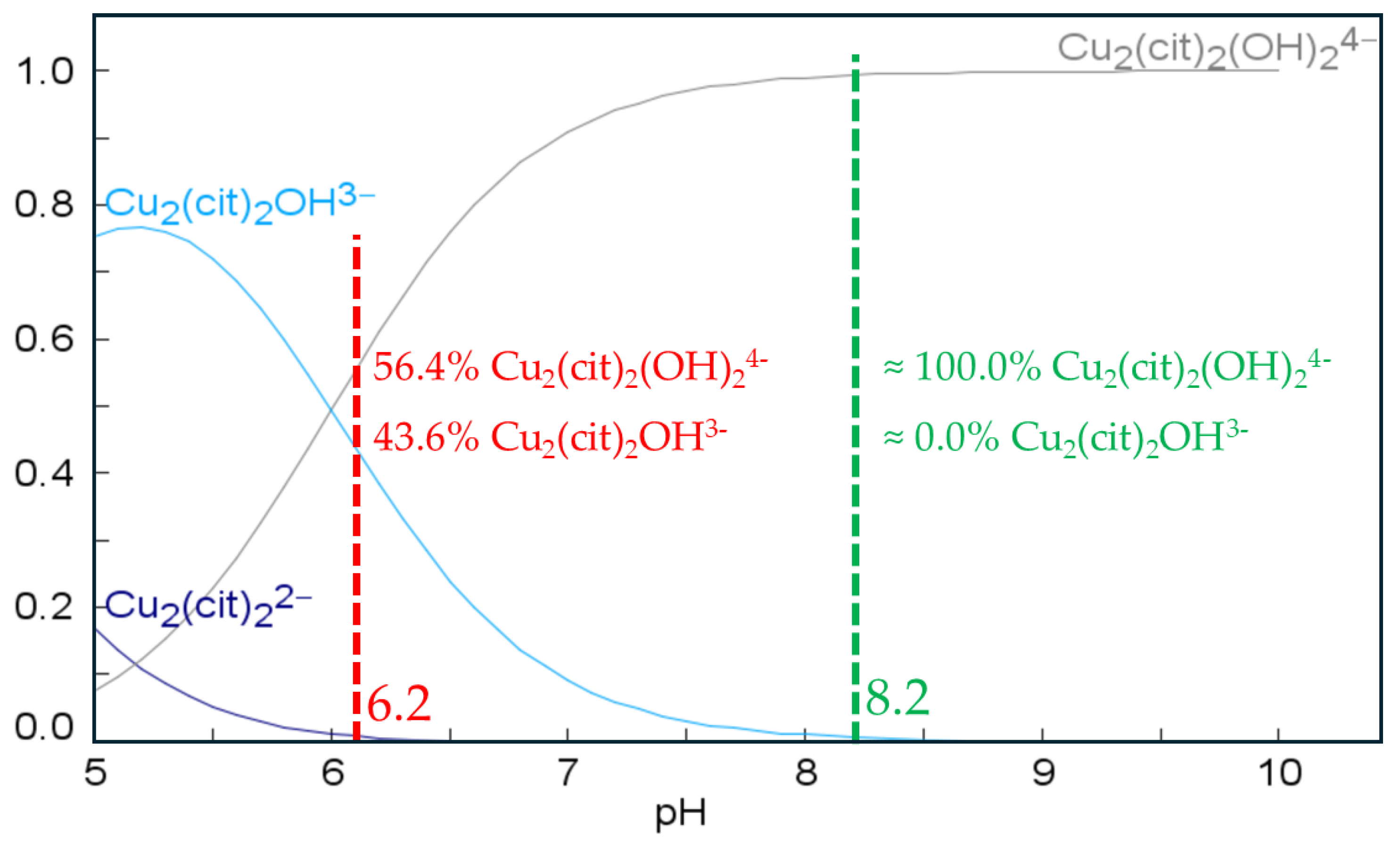
The pH determines the complexes formed by trisodium citrate and thus its effectiveness as a complexing agent for Cu [41]. The speciation analysis of the complexes in solution (Figure 2, with the same concentrations as in Figure 1) confirmed the coexistence of the Cu2(Cit)2OH3 complex (hereafter referred to as monohydroxy) and the Cu2(Cit)2(OH)23− complex (hereafter referred to as dihydroxy) at a preparation pH of 6.1. These two complexes correspond to the two oxidation peaks observed in Figure 1 (and Figure A1a). Neither in the literature nor in the software database used are the Au–citrate complexes listed, which is consistent with the previously discussed observations.
Utilizing the knowledge of species present in the electrolyte, including the complexes [Au(CN)2], monohydroxy, and dihydroxy, the electrodeposition of various AuCu alloy coatings was conducted through DC electrodeposition. The primary objective was to optimize key process parameters, such as current density, the influence of mass control via electrode rotation, and metal concentrations. Concurrently, the electrochemical behavior of Cu-Cit, monohydroxy, and dihydroxy complexes was examined as a function of pH, which was increased to 8.2 to exclusively obtain the dihydroxy complex, in alignment with the speciation depicted in Figure 2. This will allow for the observation of the influence of the monohydroxy and dihydroxy complexes on the resulting alloy composition.
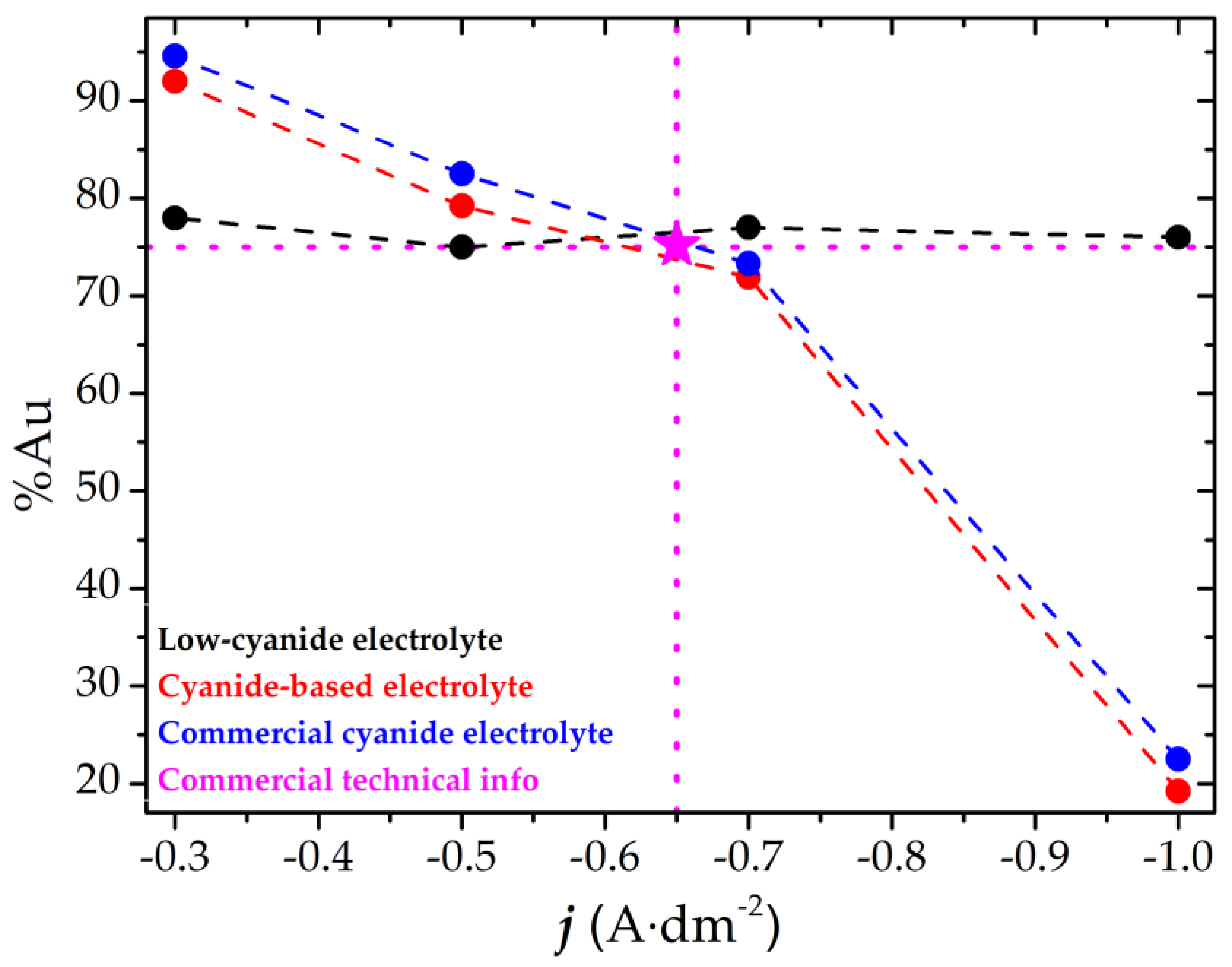
Figure 3 presents the gold content as a function of current density, within the range of –0.3 to –1.0 A·dm−2. The optimized low-cyanide electrolyte for producing 18 kt AuCu alloys consists of 15 mM of Au, 28 mM of Cu, at 65 °C, pH of 8.2, and under non-rotating conditions. These conditions were determined through a systematic analysis of each parameter, with detailed results shown in Figure A2. In addition to using a composition of 18 kts, priority was given to the parameters that enabled this composition to remain constant across the widest possible range of current densities analyzed. Starting from the initial electrolyte composition shown in Figure 1, which corresponds to a Cu concentration of 30 mM, the electrodeposited Cu percentage generally exceeded the 25% target for 18 kt Au, particularly at varying current densities.
Across the current density range of –0.5 to –1.0 A·dm−2 without rotation, alloy compositions obtained from electrolytes with Cu concentrations of 25 and 28 mM remained relatively stable. Moreover, coatings obtained without rotation were more homogeneous, underscoring the influence of electrolyte hydrodynamics and composition gradients. At pH 8.2, the coating compositions were more stable across the tested current densities, showing better results than those obtained at pH 6.1. Although Cu conditions approached the desired range, the gold content remained above the 18 kt target, prompting further optimization of the Au concentration. Under the selected conditions (28 mM of Cu, 65 °C, pH of 8.2, no rotation), the deposited Au percentage showed a direct correlation with the Au concentration and minimal variation across the current density range, a consequence of the gold species’ intrinsic stability (Table 1) and its non-interaction with citrate (Figure A1b). A Au concentration of 15 mM yielded compositions closest to 18 kt, with only minor variations across the current density range.
Figure 3 also includes the results obtained using a cyanide-based electrolyte. In this case, a strong dependence on current density was observed, which is considered unfavorable for industrial applications. A similar behavior was noted for the commercial electrolyte, despite the presence of additives. In contrast, the novel low-cyanide electrolyte exhibited significantly improved stability of gold content over a broader current density range, making it a more suitable alternative. Additionally, low-cyanide electrolyte did not require rotation during the laboratory-scale electrodeposition process, unlike cyanide-based electrolyte, where a rotation of 100 rpm was required. This difference reduces the complexity of the electrodeposition process among other advantages.
According to that, the concentration of each metal in the citrate electrolyte was the most significant determining factor in the resulting alloy composition, in contrast to the cyanide electrolyte, which is more sensitive to current density.
Upon analyzing the composition of both low-cyanide and cyanide-based electrolytes, notable differences were observed between them. Although the citrate electrolyte initially contained K[Au(CN)2] salt, the reduction in the CN was 99.1%, compared to the cyanide-based electrolyte. This decrease minimizes the ecological and safety risks, making the low-cyanide electrolyte more environmentally friendly and safer.

3.2. Coating Characterization

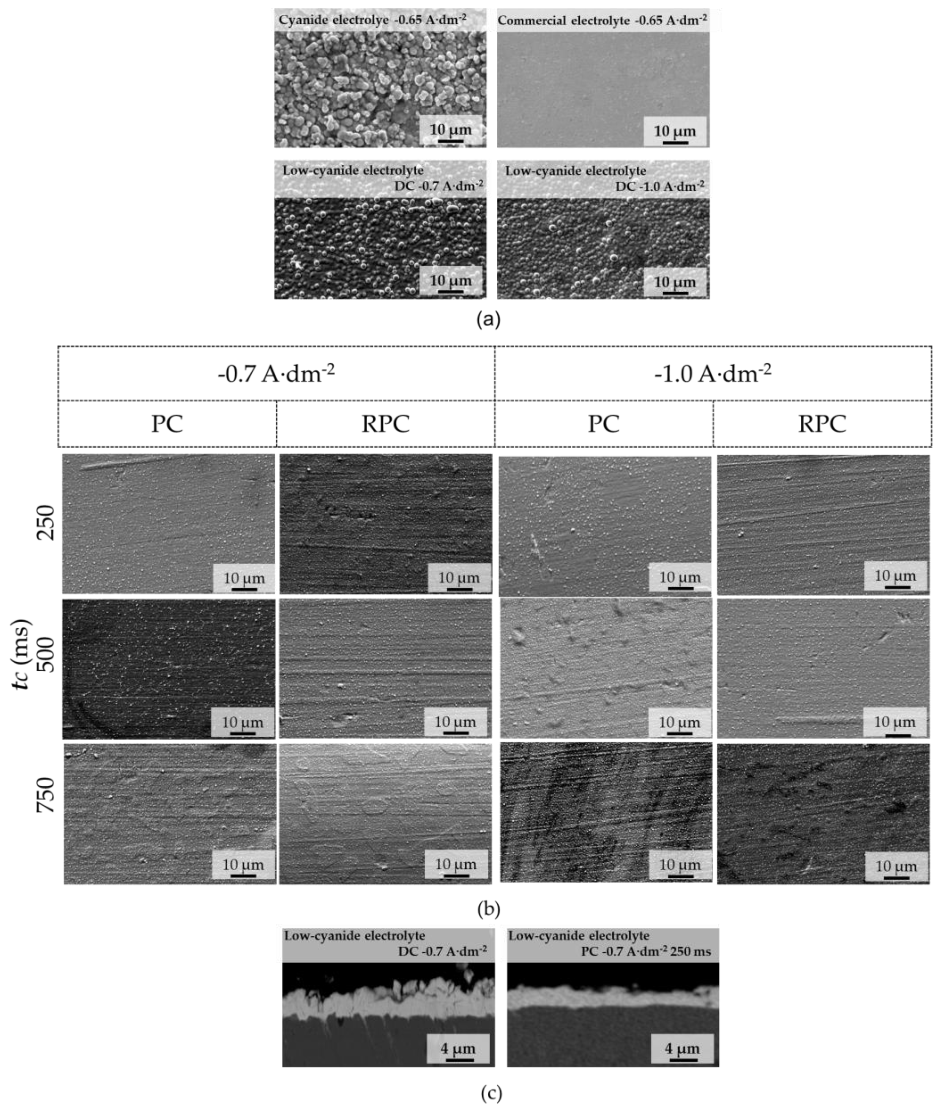
The morphological analysis is presented in detail in Figure 4, comparing the various electrolytes investigated, with particular emphasis on the low-cyanide electrolyte developed in this study. As shown under DC electrodeposition conditions (Figure 4a), the different 18 kt alloy coatings—achieved by adjusting the current density to −0.65 A·dm−2 for the samples electrodeposited using both the commercial electrolyte and the cyanide-based electrolyte—exhibited distinctive morphologies and surface roughness. The commercial sample exhibits a smooth morphology, attributed to the presence of additives in the electrolyte. In contrast, the additive-free cyanide-based formulation displays a granular morphology at the same current density of −0.65 A·dm−2. At higher current densities of −0.7 A·dm−2 and −1.0 A·dm−2, the coatings obtained using the low-cyanide electrolyte under DC conditions also exhibit granular morphologies, which could indicate an analogous effect of citrate on the uniform distribution of the coating over the electrode surface [43]. The roughness of both samples is expected to be similar to each other and markedly different from that of the commercial coating, which shows a smooth surface and, consequently, very low roughness.
Given that PC and RPC electrodeposition techniques have previously been reported to improve coating morphology [44], additional coatings were deposited using the low-cyanide electrolyte at current densities of −0.7 A·dm−2 and −1.0 A·dm−2 under PC and RPC conditions, aiming to achieve a composition close to 18 kt (Figure 4b). The parameters employed included duty cycles of 25%, 50%, and 75% (corresponding to tC values of 250 ms, 500 ms, and 750 ms, respectively). In the case of RPC electrodeposition, the jA was additionally adjusted to 20% of the applied jC, as indicated in Table 2. The results were categorized based on the tC, as this is the only parameter held constant across both PC and RPC modes for each combination of current density and duty cycle.
A pronounced transformation in coating morphology was observed, shifting from a fully granular texture to a significant reduction in agglomerate size (e.g., RPC −1.0 A·dm−2, 250 ms). Moreover, the resulting coatings exhibited a more compact structure, which contributed to enhanced properties such as increased hardness and improved adhesion to the substrate. Specifically, a decrease in tC (and thus in the duty cycle) led to a consistent reduction in surface roughness, independent of the applied current density. This behavior is likely related to changes in the diffusion and Helmholtz layer [45,46], as the tA period enabled a more efficient replenishment of electroactive species in the electrolyte. On the other hand, no significant morphological differences were observed between coatings deposited at −0.7 A·dm−2 and −1.0 A·dm−2. However, the application of an anodic pulse (jA) slightly influenced the texture of all coatings, inducing a subtle return toward a more granular morphology. The decrease in sample roughness due to the application of current pulses was confirmed through cross-sectional analysis (Figure 4c), as evidenced by the coating obtained under PC at −0.7 A·dm−2 with a tC of 250 ms, in comparison to the coating produced by DC electrodeposition at the same current density. This cross-sectional analysis also enabled the determination of the average thickness of all coatings obtained, which was approximately 3 µm, regardless of the electrolyte used.
The application of different duty cycles also resulted in variations in alloy composition, as shown in Figure A3. At a current density of −1.0 A·dm−2, the composition closest to 18 kt was achieved, particularly at tC of 500 and 750 ms. Therefore, subsequent characterizations were performed using these deposition parameters.
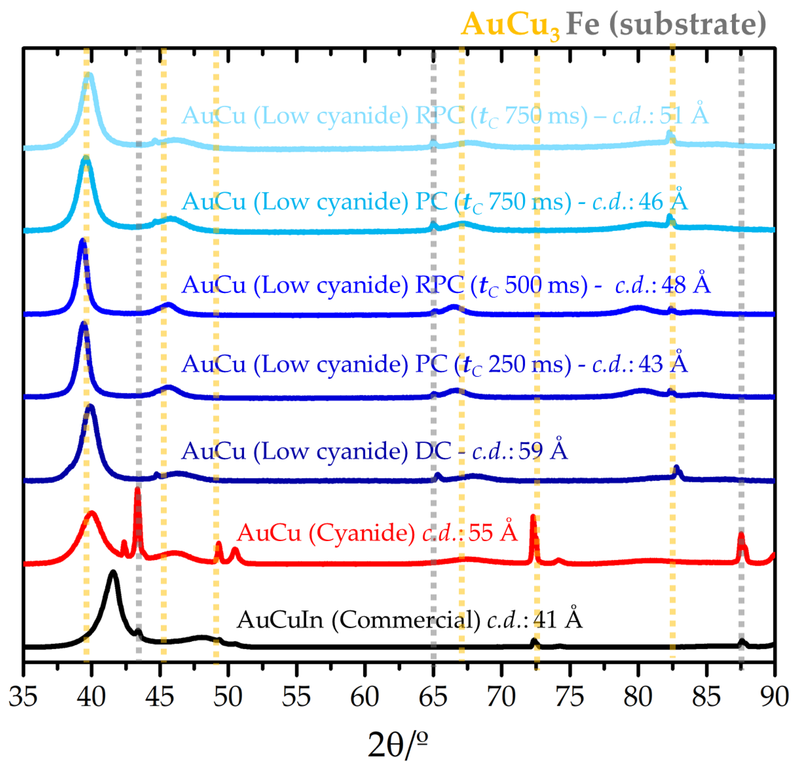
The variability in textures observed in Figure 4 reflects notable changes in the microstructure, which can significantly influence the mechanical properties of the coatings [47,48]. Therefore, the microstructures of coatings electrodeposited under DC, PC, and RPC conditions were analyzed. For comparison purposes, a commercial coating and a AuCu coating obtained from a cyanide-based electrolyte were also included. The corresponding results are presented in Figure 5.
All diffractograms exhibit the AuCu3 phase, with a characteristic base peak at 39°, along with additional peaks corresponding to the α-Fe substrate. In the commercial sample, a shift in the base peak to 40.3° was observed, attributed to the presence of indium, although no distinct peak corresponding to this element was detected. Moreover, no diffraction peaks related to pure gold were identified, thereby ruling out any chemical deposition of elemental Au.
Grain refinement may be attributed to both the action of the complexing agent and the specific deposition parameters employed [49]. Among the analyzed samples, notable differences in crystallinity were observed. The AuCu alloy deposited from the low-cyanide electrolyte under DC conditions exhibited a crystal domain (c.d.) size of 59 Å, slightly larger than the 55 Å observed for the cyanide-based coating. Although the difference was only 4 Å, the higher current density used in the citrate system would theoretically promote smaller c.d. sizes. This suggests that cyanide-based electrolytes are more effective in refining the alloy’s structure, likely by stabilizing specific crystallographic planes and limiting uncontrolled crystal growth. The difference with the commercial coating was even more pronounced, reaching 18 Å; however, the presence of proprietary additives in the commercial electrolyte must also be considered.
Coatings deposited using pulsed current with tC values of 500 ms and 750 ms exhibited c.d. sizes of 43 Å and 46 Å, respectively. These conditions enhanced nucleation over crystal growth more efficiently than DC deposition, leading to a reduction in c.d. size. The slight increase in c.d. size at 750 ms suggests a modest degree of structural reorganization and crystal growth, although this effect was secondary to that of pulse modulation. The resulting c.d. sizes were close to that of the commercial coating, differing by only 5 Å and 3 Å, respectively. In the case of RPC electrodeposition at −1.0 A·dm−2 with tC values of 500 ms and 750 ms, the c.d. sizes were found to be 48 Å and 51 Å, respectively. This technique appears to promote more ordered crystal growth compared to PC, likely due to the relaxation of internal stresses and defect reduction during the polarization reversal. Similarly to the PC mode, a lower tC resulted in a slight increase in c.d. size, indicating improved structural reorganization under these conditions.
Reports in the literature show that the crystalline domain sizes of coatings obtained using a thiourea complexing agent and a non-cyanide gold precursor (HAuCl4) are similar to those achieved with the low-cyanide electrolyte proposed in this study, electrodeposited under DC conditions, with domain sizes on the order of 60 Å [29]. By using citrate as a complexing agent, a significant reduction in crystalline domain size has been achieved under PC and RPC conditions, reaching values around 43 Å. This range of crystalline domain sizes aligns with previously reported studies using KAu(CN)2 and non-cyanide complexing agents [2], with alloy compositions similar to 18 kt, where c.d. as low as 40 Å were attained. These findings highlight the advantages of using such gold precursor salts, particularly in enhancing the mechanical properties of the resulting coatings.
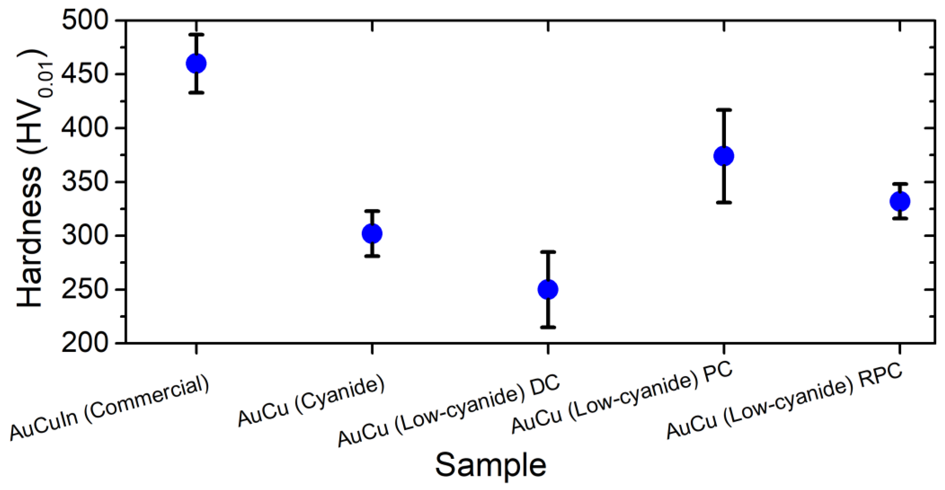
The variability in c.d. sizes suggests corresponding differences in the mechanical properties of the coatings. Among these, hardness is one of the most directly correlated with microstructural characteristics; according to the Hall–Petch relationship, increased grain refinement leads to higher material hardness. Therefore, the microhardness of several thick coatings electrodeposited from the low-cyanide electrolyte at a current density of −1.0 A·dm−2, and tC of 500 ms in the case of PC and RPC samples, were evaluated. The results are presented in Figure 6.
Consistently with the previous microstructural analysis, the AuCu alloy deposited from the citrate electrolyte under DC electrodeposition conditions exhibited a considerably lower hardness (~275 HV0.01) compared to both the commercial AuCuIn coating and the AuCu alloy deposited from the cyanide-based electrolyte. The notable difference from the commercial sample persisted, despite the expected contribution of indium to grain refinement and, consequently, increased hardness.
In contrast, the AuCu coating obtained via PC electrodeposition exhibited a significantly higher hardness value of approximately 370 HV0.01, surpassing that of the cyanide-based AuCu DC coating and the values reported in the literature [29], around 279 HVN, using HAuCl4 and thiourea as the complexing agent. The sample deposited using RPC electrodeposition yielded a similar hardness to the PC coating, with variations falling within the experimental margin of error. As observed for the coating textures, the application of pulsed currents effectively enhanced hardness, consistent with the reduction in crystallite size and in agreement with trends reported for other metallic alloys in the literature [50,51]. Nonetheless, these values remain below those of the commercial coating.
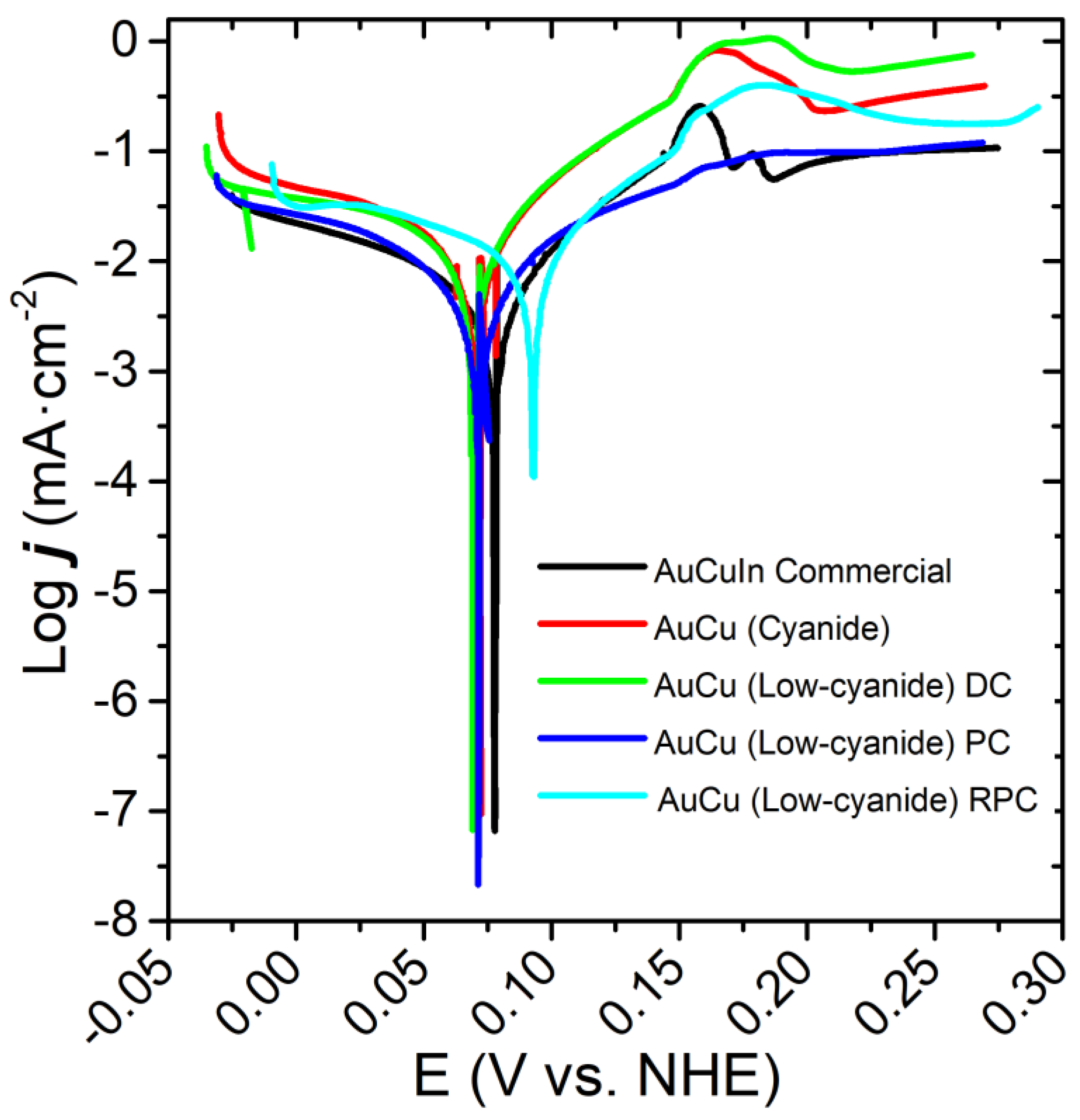
Although gold is well known for its excellent corrosion resistance, the incorporation of copper into the alloy can detrimentally affect this property in AuCu coatings [52,53]. Additionally, the choice of complexing agent plays a crucial role, as it influences the resulting microstructure of the electroplated coatings, as previously discussed. In this context, a preliminary electrochemical study was conducted to evaluate the corrosion behavior of the various deposited samples, as presented in Figure 7.
The polarization curves revealed that the commercial AuCuIn coating exhibited well-defined oxidation peaks between 0.13 and 0.20 mV, consistent with the behavior observed for coatings deposited from cyanide-based electrolytes. Given the structural similarities among the samples and the limited reference data available, these oxidation peaks may be attributed to the oxidation of copper from Cu0 to Cu2+. Similar oxidation features, albeit less pronounced, were detected in the AuCu coatings deposited from both the cyanide-based electrolyte and the low-cyanide electrolyte under DC electrodeposition conditions, suggesting that the complexing agent has a relatively minor impact on the oxidation behavior under these deposition conditions. In contrast, the coatings produced using PC and RPC electrodeposition exhibited a significant reduction in oxidation peak intensity, with the PC sample in particular showing a complete absence of oxidation peaks.
Electrochemical parameters extracted from the polarization curves (Figure 7) are summarized in Table 3. The differences in jCORR and RP among the various coatings were minor when considering the deviation of the different measurements, and generally comparable to the values obtained for the commercial sample. Slight variations were observed in ECORR, with the AuCu PC and AuCu RPC coatings exhibiting more noble potentials relative to the other experimental samples, although still lower than the commercial AuCuIn reference. Electrodeposition using PC and RPC from the low-cyanide electrolyte yielded jCORR values of the same order of magnitude as the commercial sample, representing a significant improvement over the coating obtained with DC using the same electrolyte. Compared to data in the literature, the corrosion current density of an alloy with a composition similar to 18 kt gold is approximately 240 µA·cm−2 at best [2]. This value is significantly higher than those reported in this study, where a value as low as 4.1 µA·cm−2 was achieved, indicating a much more corrosion-resistant coating. Therefore, although the use of cyanide-based gold salts offers advantages in terms of bath stability (Table 1) and improved mechanical properties relative to previous reports [2,29], the use of citrate as a complexing agent stands out particularly for its superior corrosion performance.
These corrosion results are consistent with the previously discussed compact surfaces (Figure 4), which exhibit a more controlled microcrystalline structure and reduced pathways for corrosive agents.

4. Conclusions

AuCu alloys were successfully electrodeposited using a novel low-cyanide electrolyte, demonstrating properties comparable to both commercial coatings and those obtained from conventional cyanide-based electrolytes. The optimization of the electrodeposition parameters revealed that pH is a critical role influencing the final alloy composition, primarily by modulating the distribution of copper complexes in the electrolyte. Under optimized conditions—specifically, at metal ion concentrations of 15 mM Au and 28 mM Cu—AuCu alloys with a composition equivalent to 18 kt were achieved.
Furthermore, the application of pulse current (PC) and reverse pulse current (RPC) electrodeposition techniques significantly improved the morphological quality of the coatings. Compared to those obtained by direct current (DC), PC and RPC coatings exhibited enhanced compactness and reduced porosity, thereby contributing to superior microstructural and mechanical properties.

Author Contributions

Methodology, M.A.; Formal analysis, T.A.; Investigation, M.A.; Writing—original draft, M.A.; Supervision, T.A. and M.S.; Project administration, T.A.; Funding acquisition, M.S. All authors have read and agreed to the published version of the manuscript.

Funding

The financial support from AGAUR-Generalitat de Catalunya (2021SGR00712 and “Pla de Doctorats Industrials” 2021DI020) and from the Ministerio de Ciencia, Innovación y Universidades and the European Union (MICIU/AEI/10.13039/501100011033/FEDER,UE) through projects PID2022-138491OB-C33 and CEX2021-001202-M is gratefully acknowledged.

Institutional Review Board Statement

Not applicable.

Informed Consent Statement

Not applicable.

Data Availability Statement

The original contributions presented in the study are included in the article, and further inquiries can be directed to the corresponding author.

Conflicts of Interest

Author Mohamed Amazian was employed by the company Plating Decor Services & Management. The remaining authors declare that the research was conducted in the absence of any commercial or financial relationships that could be construed as a potential conflict of interest.

Abbreviations

c.d.Crystal Domain
CVCyclic Voltammetry
DCDirect Current
EDXEnergy-Dispersive X-ray spectroscopy
FESEMField Emission Scanning Electron Microscopy
KtKarat
OCVOpen Circuit Voltage
PCPulsed Current
RPPolarization Resistance
RPCReverse Pulsed Current
SCEStandard Calomel Electrode
XRDX-Ray Diffraction

Appendix A

Figure A1. (a) Cyclic voltammograms corresponding to the Cu system without citrate (blue) and with citrate (red); (b) Cyclic voltammograms corresponding to the Au system without citrate (blue) and with citrate (purple). Experimental conditions: ambient temperature, 100 rpm, 50 mV·s−1, pH 6.1.
Coatings 15 00778 g0a1
Figure A2. (a) EDX analysis of the Au content of the electrodeposited AuCu alloy by DC, as a function of current density, [Cu], pH, and rotation; (b) %Au of the AuCu alloy electrodeposited by DC as a function of current density at different [Au], with the following experimental conditions: 28 mM of Cu, pH of 8.2, 65 °C, no rotation.
Coatings 15 00778 g0a2
Figure A3. EDX analysis of the Au content of the alloy, as a function of tC at a current density of −0.7 A·dm−2 (red) and −1.0 A·dm−2 (blue).
Coatings 15 00778 g0a3

References

  1. Giurlani, W.; Zangari, G.; Gambinossi, F.; Passaponti, M.; Salvietti, E.; Di Benedetto, F.; Caporali, S.; Innocenti, M. Electroplating for Decorative Applications: Recent Trends in Research and Development. Coatings 2018, 8, 260. [Google Scholar] [CrossRef]
  2. Zhu, Z.; Ren, P.; Meng, H. Electrodeposition of Nanocrystalline Au-Cu Alloy Coatings with High Hardness and Corrosion Resistance for Electronic Contact Application. Mater. Lett. 2023, 330, 133320. [Google Scholar] [CrossRef]
  3. Zhang, Z.; Hu, W.; Deng, Y.; Zhong, C.; Wang, H.; Wu, Y.; Liu, L. The Effect of Complexing Agents on the Oriented Growth of Electrodeposited Microcrystalline Cuprous Oxide Film. Mater. Res. Bull. 2012, 47, 2561–2565. [Google Scholar] [CrossRef]
  4. Blair, A. Gold plating in the electronics industry. Gold Bull. 1981, 14, 167–168. [Google Scholar] [CrossRef]
  5. Sullivan, M.; Kohl, P.A. Electrochemical Study of the Gold Thiosulfate Reduction. J. Electrochem. Soc. 1997, 144, 1686–1690. [Google Scholar] [CrossRef]
  6. Jo, Y.; Kim, S.-M.; Jeong, E.-S.; Lee, K.-T.; Jin, S.; Lee, W.Y.; Lee, S.-Y.; Lee, M.H. On the Role of Complexing Agents in Co-Electrodeposition of SnAg Alloy with Uniform Composition. Mater. Sci. Semicond. Process. 2023, 166, 107751. [Google Scholar] [CrossRef]
  7. Hatherley, P.G.; Watkins, K.G.; McMahon, M. The Properties of Copper Cyanide Electrolytes: A Comparison of Sodium and Potassium Formulations. Trans. IMF 1992, 70, 177–183. [Google Scholar] [CrossRef]
  8. Kohl, P.A. Electrodeposition of Gold. In Modern Electroplating, 5th ed.; Schlesinger, M., Paunovic, M., Eds.; Wiley: Hoboken, NJ, USA, 2010; pp. 115–129. [Google Scholar] [CrossRef]
  9. Bard, A.J.; Stratmann, M. (Eds.) Encyclopedia of Electrochemistry; Wiley-VCH: Weinheim, Germany, 2002. [Google Scholar]
  10. Flores, J. OMEGAL 180 CDF. Available online: https://macdermidenthone.com/solutions/precious-metals/gold/omegal-180-cdf-cadmium-free-gold-copper-indium-process (accessed on 12 April 2024).
  11. Dimitrijević, S.B.; Rajčić-Vujasinović, M.M.; Jančić-Hajneman, R.M.; Bajat, J.B.; Trujić, V.K.; Trifunović, D.D. Temperature effect on decorative gold coatings obtained from electrolyte based on mercaptotriazole—Comparison with cyanide. Int. J. Mater. Res. 2014, 105, 272–281. [Google Scholar] [CrossRef]
  12. Brett, C.M.A. Deep eutectic solvents and applications in electrochemical sensing. Curr. Opin. Electrochem. 2018, 10, 143–148. [Google Scholar] [CrossRef]
  13. Hosu, O.; Bârsan, M.M.; Cristea, C.; Săndulescu, R.; Brett, C.M.A. Nanostructured electropolymerized poly(methylene blue) films from deep eutectic solvents. Optimization and characterization. Electrochim. Acta 2017, 232, 285–295. [Google Scholar] [CrossRef]
  14. Hosu, O.; Barsan, M.M.; Cristea, C.; Săndulescu, R.; Brett, C.M. Nanocomposites based on carbon nanotubes and redox-active polymers synthesized in a deep eutectic solvent as a new electrochemical sensing platform. Microchim. Acta 2017, 184, 3919–3927. [Google Scholar] [CrossRef]
  15. Armand, M.; Endres, F.; MacFarlane, D.R.; Ohno, H.; Scrosati, B. Ionic-liquid materials for the electrochemical challenges of the future. Nat. Mater. 2009, 8, 621–629. [Google Scholar] [CrossRef]
  16. Green, T.A.; Liew, M.-J.; Roy, S. Electrodeposition of gold from a thiosulfate-sulfite bath for microelectronic applications. J. Electrochem. Soc. 2003, 150, C104. [Google Scholar] [CrossRef]
  17. Okinaka, Y.; Hoshino, M. Some recent topics in gold plating for electronics applications. Gold Bull. 1998, 31, 3–13. [Google Scholar] [CrossRef]
  18. Green, T.A. Gold electrodeposition for microelectronic, optoelectronic and microsystem applications. Gold Bull. 2007, 40, 105–114. [Google Scholar] [CrossRef]
  19. Honma, H.; Hagiwara, K. Fabrication of gold bumps using gold sulfite plating. J. Electrochem. Soc. 1995, 142, 81. [Google Scholar] [CrossRef]
  20. Osaka, T.; Kato, M.; Sato, J.; Yoshizawa, K.; Homma, T.; Okinaka, Y.; Yoshioka, O. Mechanism of sulfur inclusion in soft gold electrodeposited from the thiosulfate-sulfite bath. J. Electrochem. Soc. 2001, 148, C659. [Google Scholar] [CrossRef]
  21. Yang, J.-Q.; Yu, H.-H.; Jin, L.; Yang, F.-Z.; Wu, D.-Y.; Zhan, D.-P.; Tian, Z.-Q. Insights into the effects of chloride ions on cyanide-free gold electrodeposition. J. Electrochem. Soc. 2020, 167, 102514. [Google Scholar] [CrossRef]
  22. Honma, H.; Kagaya, Y. Gold plating using the disulfiteaurate complex. J. Electrochem. Soc. 1993, 140, L135. [Google Scholar] [CrossRef]
  23. Osaka, T.; Okinaka, Y.; Sasano, J.; Kato, M. Development of new electrolytic and electroless gold plating processes for electronics applications. Sci. Technol. Adv. Mater. 2006, 7, 425–437. [Google Scholar] [CrossRef]
  24. Kato, M.; Okinaka, Y. Some recent developments in non-cyanide gold plating for electronics applications. Gold Bull. 2004, 37, 37–44. [Google Scholar] [CrossRef]
  25. Dimitrijević, S.; Trujić, V.K.; Rajčić-Vujasinović, M.M. Development of new noncyanide technology in gold plating. In Proceedings of the 14th International Research/Expert Conference—TMT 2010, Mediterranean Cruise, 1–18 September 2010. [Google Scholar]
  26. Dimitrijević, S.; Mirić, M.; Vl, K.; Madić, B.; Dimitrijević, S. Recovery of precious (Au, Ag, Pd, Pt) and other metals by e-scrap processing. Izv. Khim. Bulg. Akad. Nauk. 2014, 46, 417–422. [Google Scholar]
  27. Smirnova, O.; Brovin, A.; Pilipenko, A.; Zhelavska, Y. Studying the kinetics of electrode reactions on copper, silver and gold in acid thiourea-citrate electrolytes. Mater. Today Proc. 2019, 6, 141–149. [Google Scholar] [CrossRef]
  28. Rapson, W.S.; Groenewald, T. Gold Usage; Academic Press: London, UK, 1978. [Google Scholar]
  29. Satpathy, B.; Kumari, A.; Das, K.; Das, S. Controlled modulation of coating morphology, mechanical properties and anti-tarnishing response of nanocrystalline Au-Cu alloy coatings electrodeposited from a thiourea (TU)-based non-toxic cyanide-free bath: Effect of current density variation. Mater. Today Commun. 2023, 37, 107390. [Google Scholar] [CrossRef]
  30. Smirnova, O.; Nikonov, A.; Pylypenko, O.; Brovin, A. Thiocarbamide-citrate electrolytes as an alternative to cyanide electrolytes in solving the problems of environmental protection and prevention of emergency situations. Mater. Sci. Forum 2021, 1038, 185–192. [Google Scholar] [CrossRef]
  31. Dolati, A.; Ghorbani, M.; Ahmadi, M.R. An electrochemical study of Au–Ni alloy electrodeposition from cyanide–citrate electrolytes. J. Electroanal. Chem. 2005, 577, 1–8. [Google Scholar] [CrossRef]
  32. Green, T.A.; Russell, A.E.; Roy, S. The development of a stable citrate electrolyte for the electrodeposition of copper–nickel alloys. J. Electrochem. Soc. 1998, 145, 875. [Google Scholar] [CrossRef]
  33. Ni, J.Q.; Han, K.Q.; Yu, M.H.; Zhang, C.Y. Effect of sodium citrate on electrochemical behaviour of copper in acid bath. Mater. Sci. Forum 2018, 913, 445–450. [Google Scholar] [CrossRef]
  34. Bigos, A.; Wołowicz, M.; Janusz-Skuza, M.; Starowicz, Z.; Szczerba, M.J.; Bogucki, R.; Beltowska-Lehman, E. Citrate-based baths for electrodeposition of nanocrystalline nickel coatings with enhanced hardness. J. Alloys Compd. 2021, 850, 156857. [Google Scholar] [CrossRef]
  35. Kazimierczak, H.; Hara, A.; Bigos, A.; Ozga, P. Electrodeposition of Zn-Mn-Mo layers from citrate-based aqueous electrolytes. Electrochim. Acta 2016, 202, 110–121. [Google Scholar] [CrossRef]
  36. Yapontseva, Y.S.; Kublanovsky, V.S.; Vyshnevskyi, O.A. Electrodeposition of CoMoRe alloys from a citrate electrolyte. J. Alloys Compd. 2018, 766, 894–901. [Google Scholar] [CrossRef]
  37. Umicore. AURUNA® 559 Fine Gold Electrolyte. Available online: https://mds.umicore.com/en/electroplating/products/product-finder/auruna-559-fine-gold-electrolyte (accessed on 1 July 2024).
  38. Chandrasekar, M.S.; Pushpavanam, M. Pulse and pulse reverse plating—Conceptual, advantages and applications. Electrochim. Acta 2008, 53, 3313–3322. [Google Scholar] [CrossRef]
  39. Mansfeld, F.; Oldham, K.B. A modification of the Stern—Geary linear polarization equation. Corros. Sci. 1971, 11, 787–796. [Google Scholar] [CrossRef]
  40. Gojo, M.; Stanković, V. Electrochemical deposition of gold in citrate solution containing thallium. Acta Chim. Slov. 2008, 55, 330–337. [Google Scholar]
  41. Shin, S.; Park, C.; Kim, C.; Kim, Y.; Park, S.; Lee, J.-H. Cyclic voltammetry studies of copper, tin and zinc electrodeposition in a citrate complex system for CZTS solar cell application. Curr. Appl. Phys. 2016, 16, 207–210. [Google Scholar] [CrossRef]
  42. Puigdomenech, “SPANA”, Chimera: 3. June 2006. Available online: https://www.amphos21.com/producto/chimera-4-2/ (accessed on 26 July 2024).
  43. Miller, B.; Menezes Affonso, S. Conductivity and other transport parameters in ammonium citrate gold baths. J. Electrochem. Soc. 1976, 123, 1006. [Google Scholar] [CrossRef]
  44. Leisner, P.; Fredenberg, M.; Belov, I. Pulse and pulse reverse plating of copper from acid sulphate solutions. Trans. IMF 2010, 88, 243–247. [Google Scholar] [CrossRef]
  45. Miura, S.; Honma, H. Advanced copper electroplating for application of electronics. Surf. Coat. Technol. 2003, 169–170, 91–95. [Google Scholar] [CrossRef]
  46. Farr, J.P.G. Electroplating, electrode kinetics and electrocrystallisation. Trans. IMF 2010, 88, 262–265. [Google Scholar] [CrossRef]
  47. Brun, E.; Durut, F.; Botrel, R.; Theobald, M.; Legaie, O.; Popa, I.; Vignal, V. Influence of the electrochemical parameters on the properties of electroplated Au-Cu alloys. J. Electrochem. Soc. 2011, 158, D223. [Google Scholar] [CrossRef]
  48. Tang, H.; Chen, C.-Y.; Yoshiba, M.; Nagoshi, T.; Chang, T.-F.M.; Yamane, D.; Machida, K.; Masu, K.; Sone, M. High-strength electroplated Au–Cu alloys as micro-components in MEMS devices. J. Electrochem. Soc. 2017, 164, D244. [Google Scholar] [CrossRef]
  49. Ijaz, A.; Kiss, L.F.; Demirel, A.L.; Varga, L.K.; Mikó, A. Tuning grain size, morphology, hardness and magnetic property of electrodeposited nickel with a single multifunctional additive. Mater. Chem. Phys. 2021, 267, 124681. [Google Scholar] [CrossRef]
  50. Bobzin, K.; Kalscheuer, C.; Hassanzadegan Aghdam, P. Impact resistance and properties of (Cr,Al,Si)N coatings deposited by gas flow sputtering with pulsed DC supply. Adv. Eng. Mater. 2022, 24, 2101021. [Google Scholar] [CrossRef]
  51. Derakhshandeh, R.; Akhbarizadeh, A.; Araghi, A. Investigating the tribochemical behavior of the hard chromium coating deposited via the electroplating method with direct and pulse current on copper substrate. Metall. Res. Technol. 2015, 112, 503. [Google Scholar] [CrossRef]
  52. Brock, J.; Zaroog, O.S. Copper Alloys: Corrosion; Elsevier: Amsterdam, The Netherlands, 2017; ISBN 978-0-12-803581-8. [Google Scholar] [CrossRef]
  53. Fujita, T.; Shiraishi, T.; Takuma, Y.; Hisatsune, K. Corrosion resistance evaluation of Pd-free Ag–Au–Pt–Cu dental alloys. Dent. Mater. J. 2011, 30, 136–142. [Google Scholar] [CrossRef]
Figure 1. Cyclic voltammograms corresponding to the Au-Cu–citrate system. Experimental conditions: ambient temperature, 100 rpm, 50 mV·s−1, and a pH of 6.1.
Coatings 15 00778 g001
Figure 2. Speciation of Cu–citrate complexes obtained with Spana® v. 0.3.0 [42] software, as a function of pH. Experimental conditions: [Cu] 0.03 M; [Cit] 0.3 M.
Coatings 15 00778 g002
Figure 3. EDX analysis of the gold content of the coatings in front of the current density obtained from the different electrolytes.
Coatings 15 00778 g003
Figure 4. (a) Morphology of the electroplated coatings in DC using the commercial, cyanide, and low-cyanide electrolytes. (b) Morphology of the electroplated coatings by PC and RPC in the case of low-cyanide electrolyte, with a j of −0.7 A·dm−2 and −1.0 A·dm−2, classified by tC. (c) Analysis-example of the thickness of the coatings obtained throughout the study. All analyses were carried out using FESEM.
Coatings 15 00778 g004
Figure 5. Diffractograms corresponding to the AuCu 18 kt alloys electroplated from a citrate electrolyte with a current density of −1.0 A·dm−2, AuCu 18 kt from a cyanide electrolyte, and AuCuIn from a commercial electrolyte. The identified phases were PDF #00-025-1220 (AuCu3) and PDF #00-006-0696 (Fe).
Coatings 15 00778 g005
Figure 6. Microhardness in Vickers scale of different samples of AuCu alloy from the low-cyanide electrolyte at a current density of −1.0 A·dm−2 and tC of 500 ms in the case of PC and RPC samples, the commercial AuCuIn alloy, and the AuCu alloy from the cyanide-based electrolyte.
Coatings 15 00778 g006
Figure 7. Polarization curves of the different samples analyzed. The scan rate was 1 mV·s−1 in a 3.5% NaCl medium.
Coatings 15 00778 g007
Table 1. Overview of the main Au(I) complexes and their relative stability in aqueous solution. The stability constants (log β) represent the overall formation constants of the species. Standard electrode potentials (E0 vs. NHE) are provided when available [1].
Species Au(I)log βE0 (V) vs. NHEReference
Au(CN)238.7−0.595[12]
Au(S2O3)(SO3)25−30.8[13]
Au(S2O3)(SO3)23−27.1[14]
Au(SO3)23−26.80.111[15]
Au(S2O3)23−26.10.153[12]
Au(SCN)217.50.662[12]
AuCl29.21.154[12]
Table 2. Current parameters used for PC and RPC techniques.
Techniquej (A·dm−2)jC (A·dm−2)tC (ms)jA (A·dm−2)tA (ms)
PC0.72.82500750
1.4500500
0.9750250
1.04.0250750
2.0500500
1.3750250
RPC0.72.82500.56421
1.45000.28362
0.97500.18239
1.04.02500.80412
2.05000.40341
1.37500.26221
Table 3. Electrochemical corrosion parameters determined for each sample. The samples in the low-cyanide medium were obtained with a j of −1.0 A·dm−2. The AuCu PC and AuCu RPC samples have a tC of 500 ms.
SampleECORR (mV vs. NHE)jCORR (µA·cm−2)RP (Ω·cm−2)
Commercial AuCuIn74.0 ± 20.54.8 ± 2.64349 ± 130
AuCu (Cyanide)74.7 ± 5.016.1 ± 1.8732 ± 102
AuCu (Low-cyanide) DC70.5 ± 0.826.8 ± 2.8624 ± 36
AuCu (Low-cyanide) PC78.5 ± 5.14.1 ± 0.04061 ± 114
AuCu (Low-cyanide) RPC83.9 ± 14.47.8 ± 1.71854 ± 120
Disclaimer/Publisher’s Note: The statements, opinions and data contained in all publications are solely those of the individual author(s) and contributor(s) and not of MDPI and/or the editor(s). MDPI and/or the editor(s) disclaim responsibility for any injury to people or property resulting from any ideas, methods, instructions or products referred to in the content.