Article

Numerical and Experimental Study of Enhanced Heat Dissipation Performance of Graphene-Coated Heating Cables

1
College of Mechanical Engineering, Zhejiang University of Technology, Hangzhou 310014, China
2
Zhejiang Key Laboratory of High-Precision and Efficiency Hybrid Processing Technology and Equipment, Zhejiang University of Technology, Hangzhou 310023, China
*
Author to whom correspondence should be addressed.
Coatings 2025, 15(7), 777; https://doi.org/10.3390/coatings15070777
Submission received: 30 April 2025 / Revised: 24 June 2025 / Accepted: 28 June 2025 / Published: 30 June 2025
(This article belongs to the Section Surface Characterization, Deposition and Modification)

Abstract

Low-temperature radiant heating systems utilizing heating cables face challenges including low heat dissipation efficiency and high energy consumption, hindering widespread application. Graphene coatings, characterized by high thermal conductivity and far-infrared radiation properties, offer a novel approach to enhance cable heat dissipation efficiency. This study systematically investigates the effects of coating position, thickness, and ambient temperature on cable heat dissipation using numerical simulations and experiments. A three-dimensional heat transfer model of the heating cable was established using Fluent software (2022R1). The radiation heat transfer equation was solved using the Discrete Ordinates (DO) model, and the coating position and thickness parameters were optimized. The reliability of the simulation results was validated using a temperature-rise experimental platform. The results indicate that graphene coatings significantly improve the heat dissipation performance of cables. Under optimal parameters (coating thickness: 100 μm, coating position: aluminum fin surface, initial temperature: 5 °C), the heat flux increased by approximately 26%, aluminum fin surface temperature decreased to 41.5 °C, and experimental temperature-rise efficiency improved by nearly 50%. The discrepancy between simulated and experimental results was within 8.5%. However, when coating thickness exceeded 100 μm, interfacial thermal resistance increased, reducing heat dissipation efficiency. Additionally, higher ambient temperatures suppressed heat dissipation. These findings provide a theoretical basis for optimizing the energy efficiency of low-temperature radiant heating systems.

1. Introduction

Low-temperature radiant heating via heating cables primarily relies on radiative heat transfer. However, limitations such as restricted radiation range and slow temperature rise prevent uniform room heating. To meet the required temperature-rise rate under safe operating conditions [1], common practices involve installing additional cables, inevitably increasing thermal load and electricity consumption. Enhancing the heat dissipation capacity and expanding the effective heat transfer area of heating cables are critical for achieving rapid temperature rise while conserving energy.
Graphene, with its exceptional thermal conductivity (up to 5300 W/(m·K)) [2], enables rapid heat conduction and uniform temperature distribution. Its large specific surface area (2630 m2/g) [3] further enhances radiative heat transfer. Graphene-based nanocoatings, composed of fillers, stabilizers, binders, and graphene, can increase the surface emissivity of substrates to over 0.9, thereby improving heat dissipation efficiency.
Current research on enhancing cable heat dissipation focuses on structural design, installation materials, and parameters [4,5,6]. Fin-enhanced heat transfer technology significantly increases the heat transfer surface area and improves the thermal convection efficiency of heating cables. Fin-enhanced heat transfer technology significantly increases the heat transfer surface area and improves convective efficiency. Wang [7] investigated correlations between fin spacing, height, and airflow dynamics, demonstrating non-monotonic variation in photovoltaic panel temperature with reduced fin spacing under natural convection. Recent advances highlight critical geometric and flow parameter optimizations: Guan et al. [8] numerically analyzed double-channel radiators for diesel locomotives, establishing that increasing cooling air inlet velocity from 11 m/s to 15 m/s elevates the heat transfer coefficient by 19% but increases pressure drop by 73.4%, with experimental validation showing <7.72% error. Majmader and Hasan [9] demonstrated that modified fin geometries—spike-rib, wavy, and cut-section—enhance radiator heat transfer by 131% via induced turbulence, while 38 perforations further augment convective heat transfer by 13% through boundary layer disruption. Tran and Wang [10] optimized louvered fins in mini-channel flat-tube radiators, identifying 27° as the critical louver angle minimizing thermal resistance; their composite straight-louvered fin design improved thermal performance by 55%–60% at 20 W pumping power through synergistic flow redirection. Vortex-generator fin studies by Habibian et al. [11] revealed that louvered fins achieve 24.6% higher heat transfer than plain fins despite a 67.7% increase in pressure drop, while nanofluids (CuO/Al2O3) counteract antifreeze-induced a 12.9% performance degradation through enhanced thermal conductivity. Radiator aging effects studied by Lipnický et al. [12] showed that coolant aging (50,000 km mileage) doubles cooling time from 4 min to 8.5 min in automotive systems, though the efficiency index JF declines by only 1.9% for tubes, confirming structural robustness under operational degradation.
Graphene thermal coatings have emerged as a critical research focus for heating cable coatings due to their ultra-high thermal conductivity and radiation characteristics. Hsiao et al. [13] demonstrated a 20% increase in cooling efficiency for 50 W LEDs using molecular fan coatings under constant luminance. Zhu et al. [14] employed non-equilibrium molecular dynamics to reveal that Ni-coating reduces graphene’s thermal conductivity to 70% (single-layer) and 56% (double-layer) relative to pristine graphene. Conductivity decreased with temperature (200–700 K) but increased with width due to suppressed boundary scattering. Manasoglu et al. [15] achieved a 90% solar absorptance (+80% vs. baseline) and 87%/262% thermal conductivity enhancement in graphene-coated polyester fabrics (50–150 g/kg; 0.1–0.5 mm) under contact/radiative heat transfer modes. Wei et al. [16] compared coating methodologies: blade-coated graphene fabrics exhibited in-plane/cross-plane conductivity of 2.08/0.48 W/(m·K) (anisotropy ratio: 4.3), reducing molten metal splash-induced temperature rise by 30% (19 °C vs. 27 °C). Dong et al. [17] implemented sulfonated graphene (S-GNS) coatings in aluminum foam/polyoxymethylene composites, attaining 2.25 W·m−1·K−1 thermal conductivity with optimized heat flux paths confirmed by ANSYS simulations (2022R1). Almonti et al. [18] validated enhanced thermal performance in Cu-graphene-coated micro-engine heads through thermography and FEM analysis. Lv et al. [19] engineered graphene-coated vertically aligned CNT/graphite structures achieving 32.96 W/m·K cross-plane conductivity (+60% vs. uncoated), verified via laser-induced thermochromism. Zhang et al. [20] developed poly(vinylidene fluoride-co-hexafluoropropylene)/graphite radiative cooling composites, yielding a 15.5 °C daytime temperature reduction on heat sources with ≤2 °C surface uniformity and 7% heat dissipation enhancement.
Integrated numerical and experimental methodologies critically enable the optimization of heating cable thermal performance. Installation parameter studies demonstrate that Perović et al. [21] achieved a 15% ampacity enhancement through Particle Swarm Optimization-optimized bedding geometry and conductor arrangements absent auxiliary cooling. Complementing this, Masnicki et al. [22] established a laboratory platform validating enhanced current-carrying capacity via thermal distribution mapping of tailored fillers in casing pipes. Thermal enhancement innovations reveal that Cvetković et al. [23] attained a 23% thermal uniformity improvement using graphene-alumina coatings, with Fluent simulations indicating a 26.7% thermal flux elevation at 100 μm thickness, though optimal coating requires ambient-temperature-responsive adjustment. Installation thermodynamics analyses, as confirmed by Lu et al. [24], modeled 500 kV tunnels and showed that horizontal arrangements reduce heat generation versus triangular configurations. In parallel, Nie et al. [25] quantified load capacity variations across burial methods. Safety thresholds were defined by Xie et al. [26] through critical insulation temperature experiments, while Lei et al. [27] formulated fin inclination-cooling efficiency correlations. These findings collectively inform a tripartite experimental framework for graphene-coated heating cables: (1) implementation of bedding geometry optimization principles for spatial configuration; (2) integration of dynamic coating thickness-ambient temperature coupling models; and (3) application of multi-medium thermal dissipation validation. This integrated “coating-installation-dissipation” paradigm enables a comprehensive thermal performance assessment under operational constraints.
Despite significant progress, persistent challenges remain in mass production techniques, standardization gaps, and cost control. Notably, the thickness–adhesion balance in graphene coatings requires further resolution and long-term service validation. Mallick demonstrated that coating thickness critically influences defect density and residual stress; thicker coatings exhibit increased porosity, compromising barrier properties, while thinner coatings face durability concerns regarding adhesion [28]. Aluminum fin extrusion processes require significant refinement in die wear resistance and dimensional accuracy. Ji emphasized that precise control of extrusion temperature and speed is essential to prevent mold adhesion, localized overheating, and reduced service life, necessitating parameter optimization via finite element analysis [29].
Furthermore, standardization is impeded by intricate coating methodologies: Fang employed a multi-step sol-gel and dip-coating process to achieve conductive graphene layers on fibers, revealing high sensitivity of conductivity to coating thickness and coverage uniformity [30]. Zhang utilized electrophoretic deposition for graphene coatings, highlighting significant performance variations dependent on the deposition process [31]. Liu’s CVD studies on cemented carbides further demonstrated that film composition and thickness are highly sensitive to gas flow rates and substrate composition [32].
Future research should integrate multiphysics simulations with experimental validation to investigate dynamic heat transfer mechanisms in graphene–aluminum composite structures, advancing efficient low-temperature radiant heating systems. Developing high-thermal-conductivity graphene composite coatings for aluminum fin sheaths could simultaneously enhance heat dissipation and reduce insulation degradation in heating cables. This study pioneers the identification of critical coating thickness (100 μm) and ambient temperature’s nonlinear impacts on thermal performance through coupled simulations and experiments, providing essential optimization guidelines for engineering applications.

2. Materials and Methods

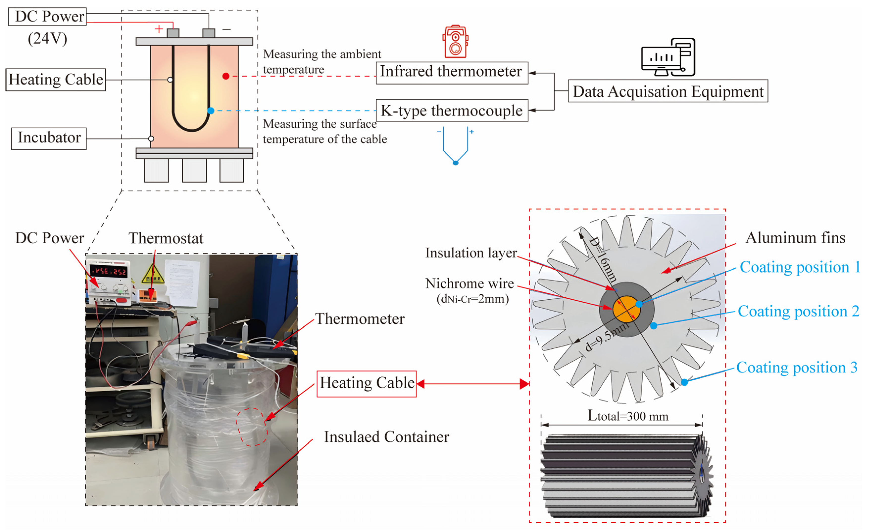
2.1. Experimental Apparatus

The experimental apparatus, as illustrated in Figure 1, consists of the following components: a temperature controller, DC power supply, temperature data acquisition unit, heating cable, and insulated container. The experimental principle is as follows: the DC power supply regulates the heating rate of the nickel–chromium alloy wire, while the temperature controller maintains the wire’s temperature at a preset value. Heat is dissipated from the aluminum fin sheath to the external air-filled layer via convection and radiation. This process elevates the temperature of the insulated container’s inner wall over time until thermal equilibrium is achieved. The electrical energy consumed corresponds to the heat dissipated through the aluminum fin sheath during the same period, as manifested by the temperature rise of the insulated container’s inner wall. The thermal equilibrium equation is expressed as:
P · t = Q c + Q d t
The experimental setup, as shown in Figure 1, positions the heating cable within the insulated container. The nickel–chromium alloy wire is heated via the DC power supply, while the data acquisition system records temperature data from four distinct locations on both the container interior and aluminum fin surfaces. Heating cables with coating thicknesses ranging from 0 μm to 300 μm were tested. Input power was regulated by adjusting the voltage through a DC regulated power supply.

2.2. Experimental Testing Methodology

The test heating cables (with uncoated specimens as the control group) were positioned within the insulated container. K-type thermocouples were installed at four measurement points on both the coated/aluminum fin surfaces of the heating cables and the container interior, ensuring tight contact with cable surfaces. The nickel–chromium alloy wire was connected to a DC power supply, with its temperature monitored by K-type thermocouples and maintained constant via feedback control to the temperature controller. Temperature sensors recorded inner wall and fin surface temperatures. Heating was terminated upon achieving thermal equilibrium within the container. The power supply was disconnected, cables with varying coating thicknesses were substituted, and the procedure was repeated.

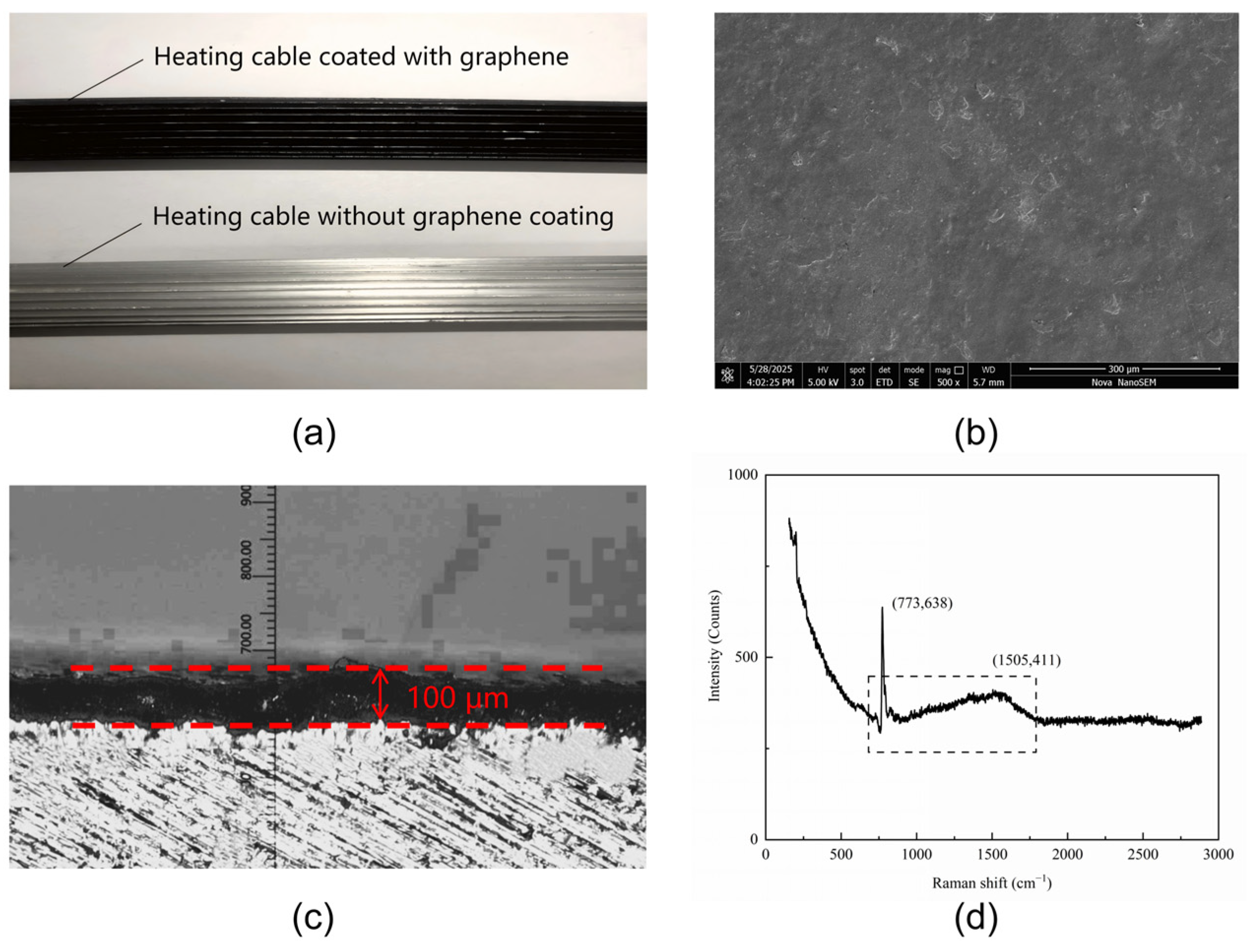
2.3. Preparation and Properties of Coatings

Graphene thermal coatings were formulated using waterborne polyurethane resin (matrix, 60%–70%), graphene oxide powder (filler, 25%–35%), and curing agent (1%–5%). Thermal conductivity (6~10 W/(m·K)) was measured via the transient plane source method using a DRE-III multifunctional thermal conductivity tester. Emissivity was calculated through infrared thermography and heating platform temperature data. Adhesion testing followed the GB/T 1720-2020 standard [33] for organic coatings on metallic substrates, with grades ranging from 1 (highest) to 7 (lowest). Table 1 summarizes the thermal conductivity, emissivity, and adhesion grades across different coating thicknesses.

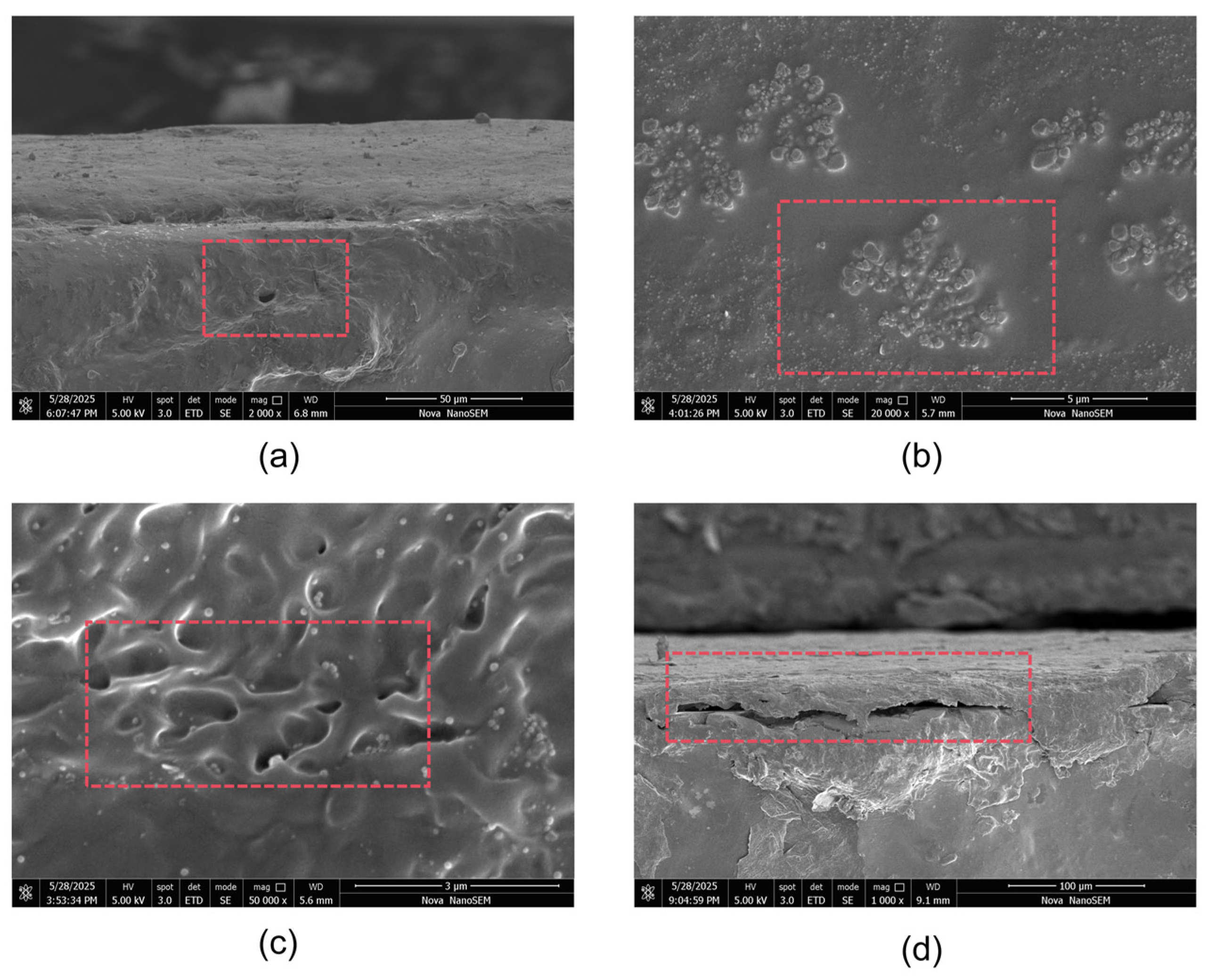
2.4. Surface Analysis of Graphene Coating

In order to systematically evaluate the engineering applicability of graphene heat dissipation coating, this study comprehensively analyzes the surface characteristics of the coating through multi-scale characterization technology.
Figure 2a shows a continuous and uniform graphene coating formed on the aluminum fin substrate (coverage > 98%), satisfying the integrity requirements for thermal interface materials. Figure 2b, characterized by SEM, reveals a macroscopically smooth coating matrix (roughness Ra < 1.5 μm) with localized regions (15%–20%) exhibiting a lamellar fish-scale stacking morphology (stacking height 2–5 μm). This micro/nano-topological feature ensures surface planarity while promoting turbulent flow for enhanced heat dissipation. The cross-sectional analysis in Figure 2c confirmed that the coating thickness on the metallic substrate strictly adheres to the process specification (100 ± 10 μm). Figure 2d Raman spectroscopy validates the coating quality: The inset shows a prominent G-band (1580 cm−1), evidencing the characteristic multilayer graphene structure (>5 layers) and indicating a highly crystalline sp2 carbon network enabling efficient in-plane thermal conduction. The broadened 2D peak and flat spectral baseline collectively demonstrate excellent overall coating uniformity and confirm that interfacial compatibility meets engineering requirements, with the structural integrity and interfacial stability fulfilling the technical specifications for wire thermal management.

2.5. Comparison of Performance Indexes of Heating Cables

Table 2 below is a performance index comparison table for heating cables, which compares the performance of different coating thicknesses (e.g., 50/100/200/300 μm) in key parameters (thermal conductivity, surface emissivity, temperature reduction efficiency) and different ambient temperatures (e.g., 25 °C/50 °C/75 °C).

2.6. Temperature Measurement Error Analysis

The comprehensive uncertainty in temperature measurement comprises contributions from the K-type thermocouple (calibration error: ±0.5 °C and contact thermal resistance: ±0.3 °C), emissivity variation in infrared thermal imaging (±0.2 °C), and environmental fluctuations (±0.5 °C). Thermal conductivity measurement uncertainty originates from coating thickness deviation (±20 μm, equivalent to ±5%), contact thermal resistance (±3%), and instrument calibration error (±3%). These components combine to yield total uncertainties for both temperature and thermal conductivity measurements that meet the ≤5% requirement.

3. Heat Transfer Numerical Simulation of Heating Cable

3.1. Heat Transfer Model of Heating Cables

The heat transfer model of the heating cable was developed using a graphene differential element heat transfer framework. If we consider an infinitesimal element with volume dxdydz, the heat generation rate per unit volume is QV, and the total heat dissipated by the element over time dtdt is expressed as QVdxdydzdt. The thermal equilibrium equation is formulated as
d θ d t ρ c d x d y d z d t = Q x d x d y d z d t + λ θ x x + λ θ y y + λ θ z z d x d y d z d t
where ρ denotes density, c represents specific heat capacity, and λ is thermal conductivity. Simplifying yields:
d θ d t = a 2 θ + Q v ρ c
where ∇2 is the Laplace operator.
For heating cables with nickel–chromium alloy heating elements and aluminum fin sheaths, heat transfer to the air-filled layer occurs primarily via radiation due to limited airflow, expressed as:
q a = ε σ ( T 4 T 0 4 )
where ε is the emissivity of the aluminum alloy sheath, σ is the Stefan–Boltzmann constant 5.67 × 10⁻⁸ W/(m2·K4), T is the fin sheath temperature (K), and T0 is the ambient temperature (K).
Convective heat transfer is modeled as:
q b = h c A 1 T T 0
where hc is the convective heat transfer coefficient (W/(m2·K)), and A1 is the convective surface area.
The heat transfer mechanism of coated aluminum fin sheaths involves multiple stages: heat conduction from the aluminum fin to the coating surface; heat propagation through microscopic particle collisions and energy transfer within the material; and radiative transfer from the coating surface to the air-filled layer. Thermal radiation occurs via electromagnetic waves without requiring a medium, as expressed by:
q c = λ δ T T 1
where λ is the coating thermal conductivity (W/(m·K)), δ is the coating thickness (mm), and T1 is the coating surface temperature (K). The total radiative heat flux from the coating to the air-filled layer is expressed as:
q d = ε 1 σ T 1 4 T 0 4
where ε1 denotes the coating emissivity.

3.2. Radiation Heat Transfer Solution Model

The Fluent software provides five computational models for solving radiation heat transfer problems. The Discrete Ordinates (DO) model employs a discrete directional transport approach, decomposing the radiative transfer equation into multiple monotonic transport equations along discrete angular directions. For the air-filled layer with low optical depth and scattering coefficients, the DO model demonstrates high accuracy in simulating radiative heat transfer processes. The governing equation is expressed as:
( I λ ( r , s ) s ) + ( a λ + σ s ) I λ ( r , s ) = a λ n 2 I b λ + ( σ s / 4 π ) 0 4 π I λ ( r , s ) Φ ( s , s , ) d Ω ,
where:
λ: Radiation wavelength
r,s: Position vector and directional vector
aλ: Spectral absorption coefficient
σs: Scattering coefficient
I: Blackbody radiation intensity
Φ: Scattering phase function
a: Absorption indices
n: Refractive indices
σ: Stefan–Boltzmann constant (5.67 × 10⁻⁸  W/(m2⋅K4)5.67 × 10−8 W/(m2⋅K4))
Ω: Solid angle

3.3. Three-Dimensional Model Development

The numerical simulation adopts a heating cable comprising: nickel–chromium alloy heating wire (core diameter dNi-Cr = 2 mm); cross-linked polyethylene (XLPE) insulation layer (thickness 1 mm); and aluminum alloy 6061 fin sheath (minimum circumscribed diameter d = 9.5 mm, maximum circumscribed diameter D = 16 mm, total length Ltotal = 300 mm).
Using SolidWorks 3D modeling software (2022R1), individual components were designed and assembled following prescribed design relationships. The physical model (Figure 2) was constructed based on the aforementioned dimensions, providing the geometric foundation for subsequent finite element simulations.
Numerical modeling of thermal conductivity across varying graphene coating thicknesses reveals that both the application position and the thickness of the coating significantly influence the heat dissipation performance of heating cables. The study investigates the effects of graphene coatings applied at three critical positions (Figure 2): the exterior of the nickel–chromium alloy heating wire (Position 1); the outer surface of the insulation layer (Position 2); and the exterior of the aluminum fins (Position 3). Coating thicknesses ranging from 20 to 300 μm (20, 50, 100, 200, 300 μm) and the number of aluminum fins are systematically analyzed under fixed thermal output conditions of the nickel–chromium alloy heating core. Numerical simulations further evaluate the combined impacts of coating position, thickness variations, and ambient temperature fluctuations on heat dissipation efficiency, providing a comprehensive understanding of graphene-enhanced thermal management in heating cable systems.

3.4. Boundary Conditions and Meshing

The ICEM module in Fluent software enhances numerical simulation accuracy by enabling precise mesh generation. Primary mesh types include pyramid, wedge, tetrahedral, and hexahedral elements, with smaller mesh sizes (0.1 mm in this study) improving simulation reliability for heating cable temperature distribution. Balancing mesh quality and computational efficiency, a tetrahedral-dominant mesh configuration totaling approximately 3 million elements was adopted. Boundary conditions for the heat dissipation scenario were defined as follows: the aluminum fin sheath surface was designated as a “wall” with third-type convective boundary conditions (convective coefficient: 5 W/(m·K), ambient temperature: 5 °C). The nickel–chromium heating element maintained a fixed temperature of 70 °C, while the surrounding air-filled layer accounted for natural convection under gravitational acceleration (9.81 m/s2, negative y-axis direction). For walls requiring thermal resistance consideration, Fluent provides two approaches: (1) meshing the wall thickness to resolve heat transfer processes directly, or (2) partitioning the wall into layered cells during preprocessing to incorporate thermal resistance effects while maintaining computational tractability.
To enhance numerical simulation accuracy, unstructured meshes were generated using the ICEM module in this study. Tetrahedral elements were selected to accommodate the complex geometric features of the heating cable, such as the surface curvature of the aluminum fins. The mesh size was set to 0.1 mm to ensure adequate resolution of temperature gradients in critical regions, particularly at the contact interface between the coating and aluminum fins. Mesh quality was confirmed to satisfy simulation requirements through quality checks (maximum skewness < 0.75, average skewness ≈ 0.04). The total mesh count reached approximately 3 million elements, balancing computational efficiency with accuracy.
Grid Independence Verification: the Richardson extrapolation method and Grid Convergence Index (GCI) were employed to quantify the influence of mesh size on the results and to assess discretization error. Steady-state temperature fields of an uncoated cable were simulated using four distinct mesh sizes (0.5 mm, 0.2 mm, 0.1 mm, and 0.05 mm). Aluminum fin surface temperature (Tfin) and heat flux (q″) were compared across these resolutions (Table 3).
The results indicate that when the mesh size was refined from 0.5 mm to 0.2 mm, the GCI values for Tfin and q″ were 7.3% and 12.5% (corrected value based on table data), respectively, indicating high mesh sensitivity (exceeding the 5% threshold). Refinement from 0.2 mm to 0.1 mm yielded Tfin and q″ variation rates of 3.6% and 7.1%, with a GCI of 4.7%. Further refinement to 0.05 mm reduced variations to 0.4% with GCI < 2%. These results demonstrate that the 0.1 mm mesh satisfies convergence requirements. Consequently, this mesh size was adopted for all subsequent simulations. The following Figure 3 shows the temperature cloud map obtained by finite element simulation of the heat dissipation scenario of the heating cable without coating.

4. Experimental Results and Discussion

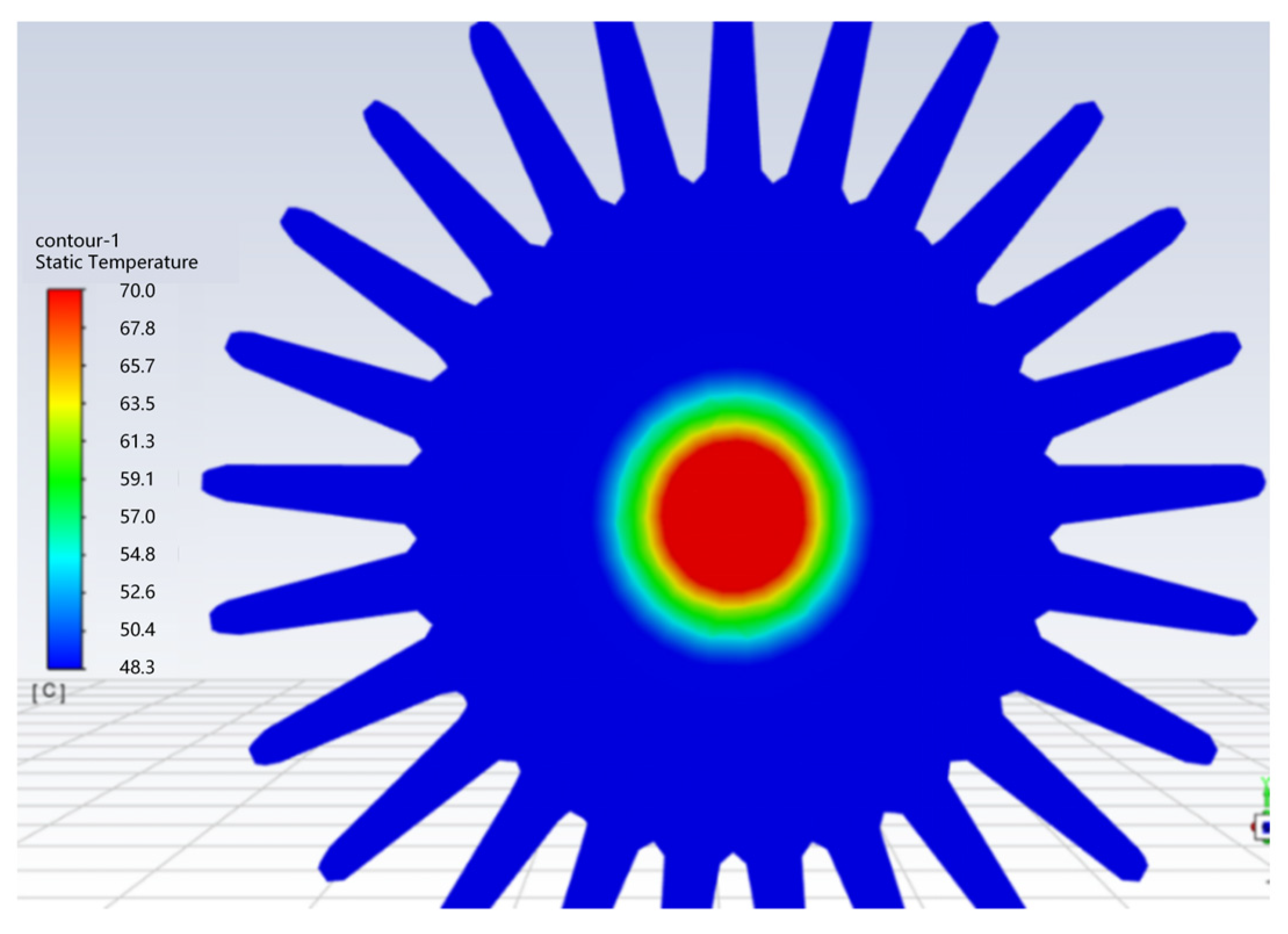
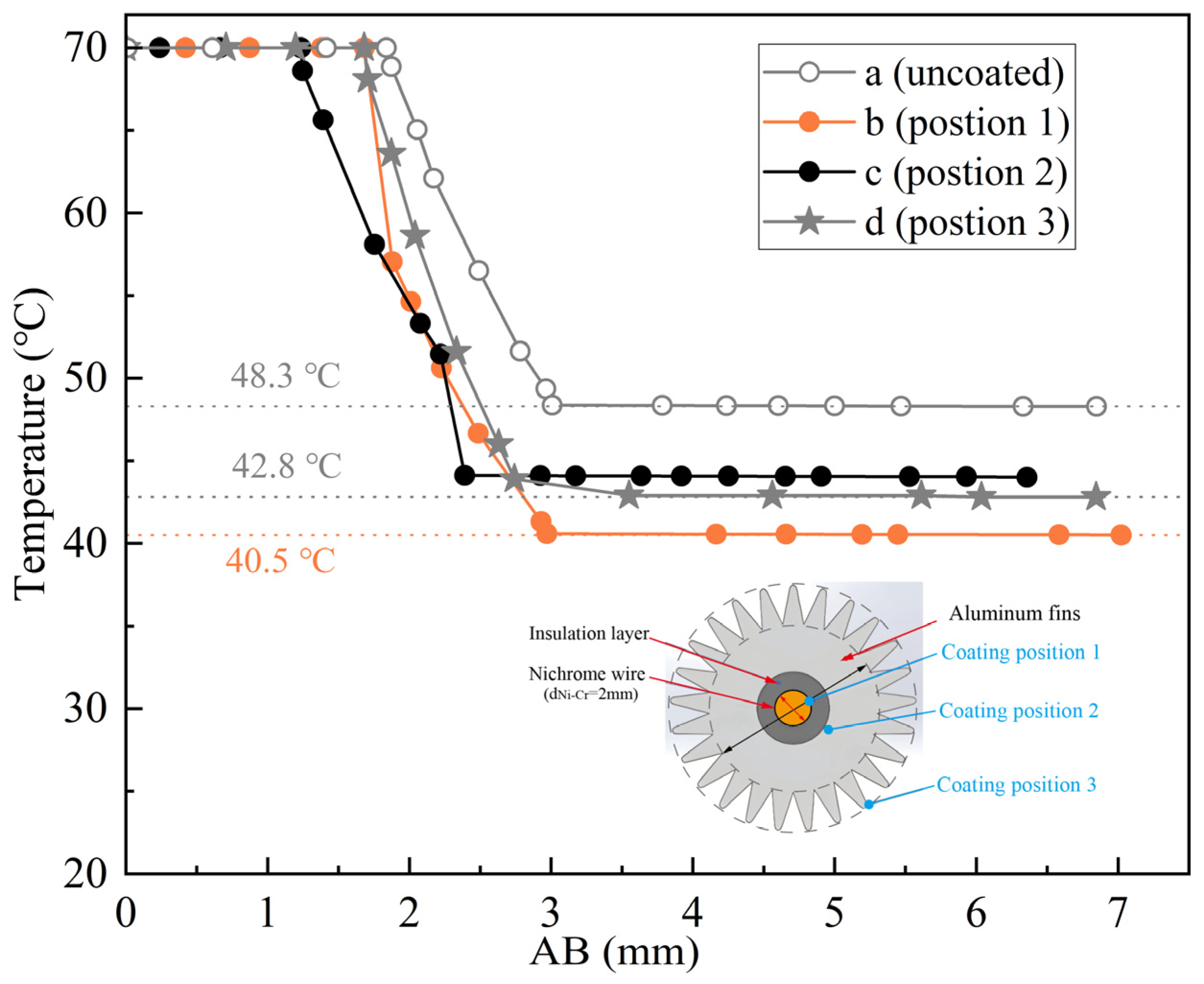
4.1. Numerical Simulation of Heat Dissipation Performance of Heating Cable with Different Coating Positions

This section investigates the impact of graphene coating positions on the heat dissipation capability of heating cables. The uncoated heating cable serves as the control group, while 100 μm thick graphene coatings are simulated to be applied at different positions, as shown in Figure 2, where Position 1, Position 2, and Position 3 correspond to the exterior of the nickel–chromium alloy wire, the exterior of the XLPE insulation layer, and the exterior of the aluminum fin sheath, respectively. All coating wall thicknesses are set to 0.1 mm, with a thermal conductivity of 155 W/(m K) and an emissivity of 0.06, and an ambient temperature of 5 °C.
Theoretically, applying a graphene coating to different positions of the heating cable increases the overall thermal resistance of heating cable and affects the heat transfer. However, to enhance the heat transfer and heat radiation capacity of heating cable with graphene coating, numerical calculation is necessary to determine the influence of the graphene coating on the heat dissipation capacity of the heating cable.
Figure 4 (Analysis of Graphene Coating Effects on Heating Cable Thermal Performance) presents the temperature profiles of heating cables with graphene coatings applied at different positions. Subfigure (a) depicts the uncoated control group, showing a relatively uniform temperature distribution due to consistent heat transfer across the cable structure. The nickel–chromium heating wire provides stable thermal output without localized overheating.
Subfigure (b) illustrates the configuration with graphene coating applied to the heating wire exterior (Position 1), where the aluminum fin surface temperature decreases to 40.5 °C. However, the overall heat flux decreases to 9590 W/m2 (20.08% lower than the control group), indicating increased thermal resistance despite enhanced localized heat transfer.
Subfigures (c) and (d) demonstrate the configuration with coating applied to the aluminum fin sheath exterior (Position 3), achieving a fin surface temperature of 42.5 °C. Here, the heat flux increases to 15,200 W/m2 (26.67% higher than the control group). Although the coating slightly reduces the overall thermal conductivity, its superior emissivity (0.95 vs. 0.85 for uncoated surfaces) dominates, improving radiative heat dissipation. Higher Qloss values (indicative of improved cooling), lower fin temperatures, and elevated heat flux collectively confirm Position 3 as optimal, delivering a 26.67% enhancement in overall thermal performance. Subsequent experiments on coating thickness and ambient temperature effects were conducted exclusively with Position 3 configurations.

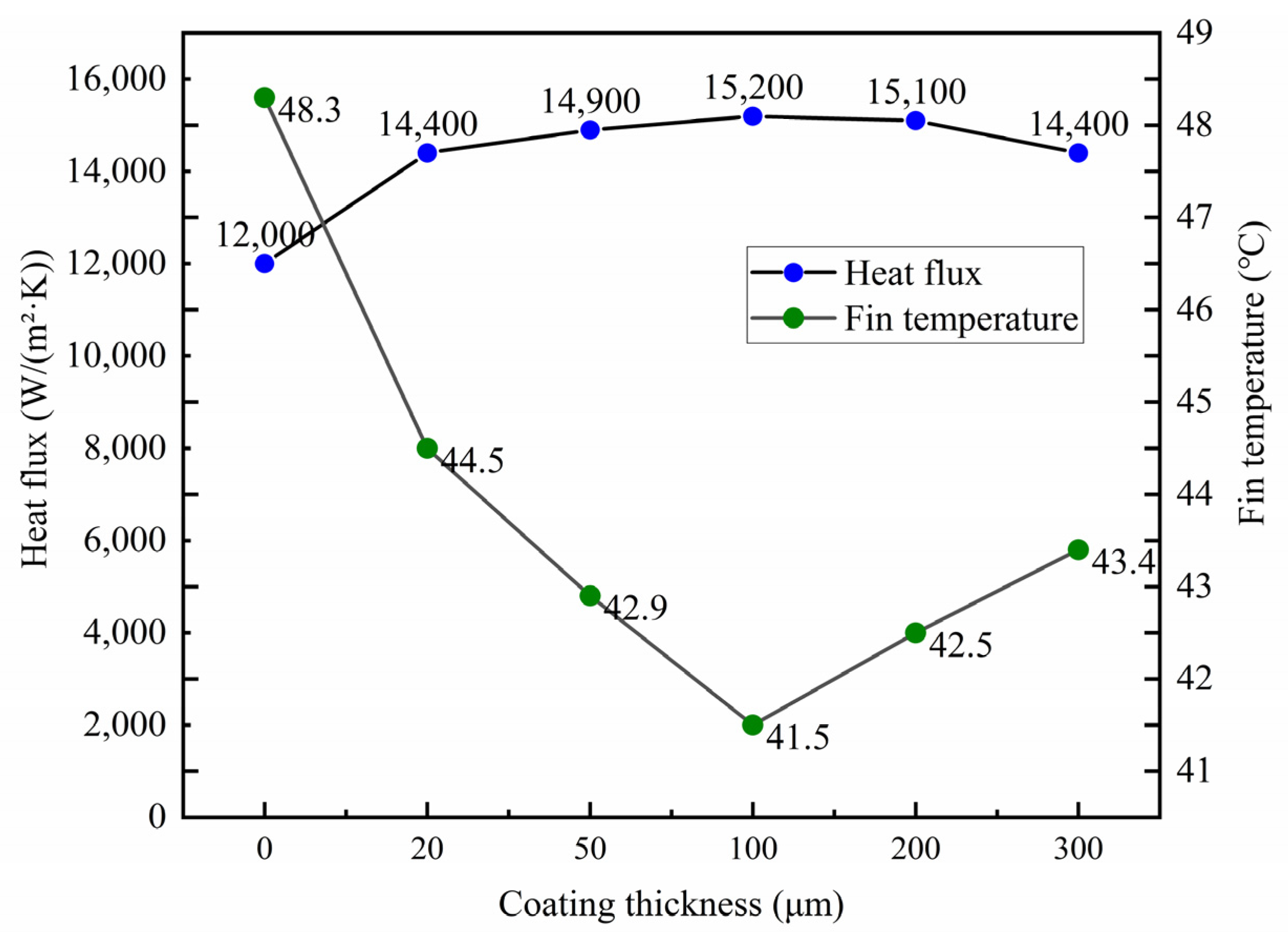
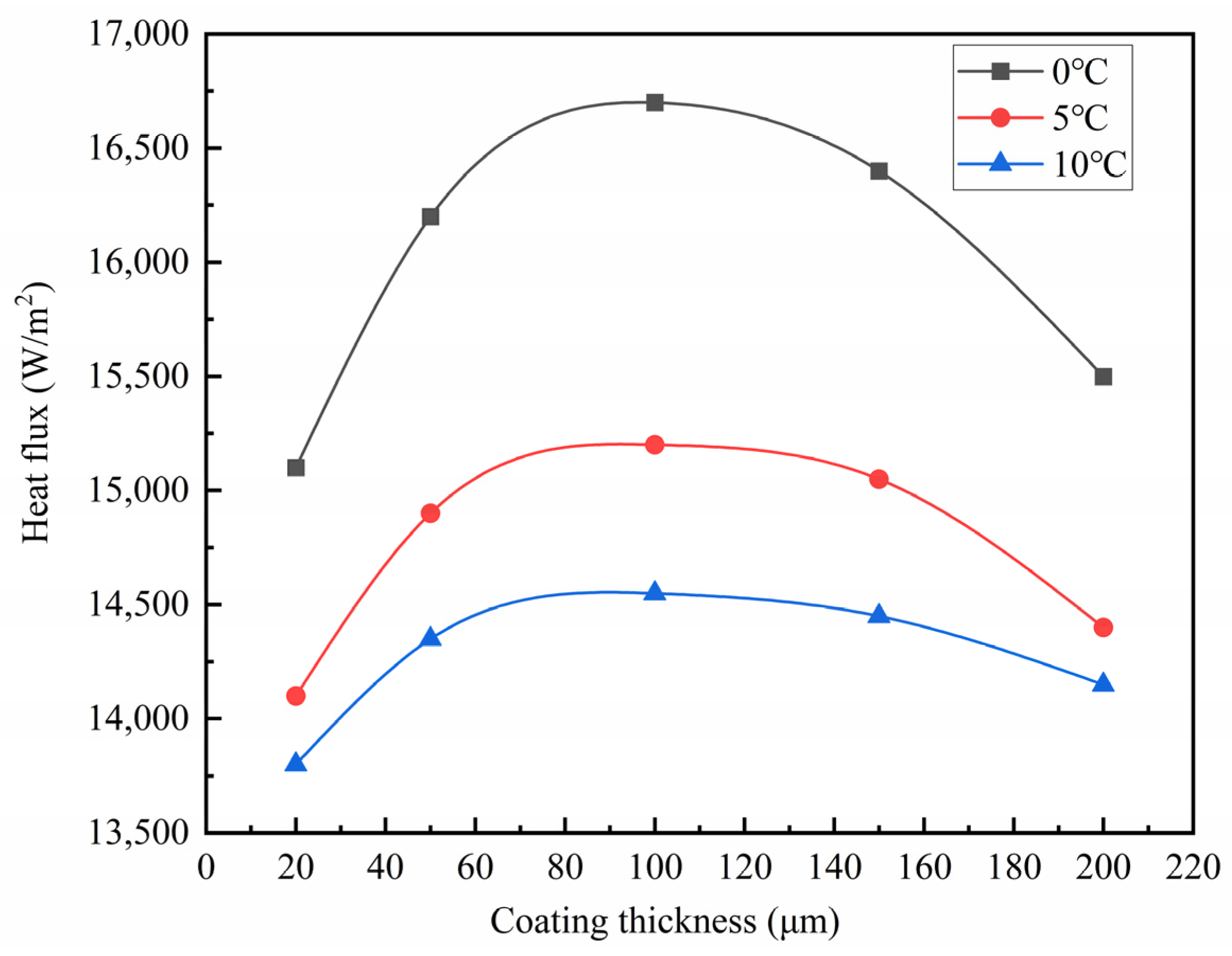
4.2. Effect of Coating Thickness on Temperature Rise of Heating Cable

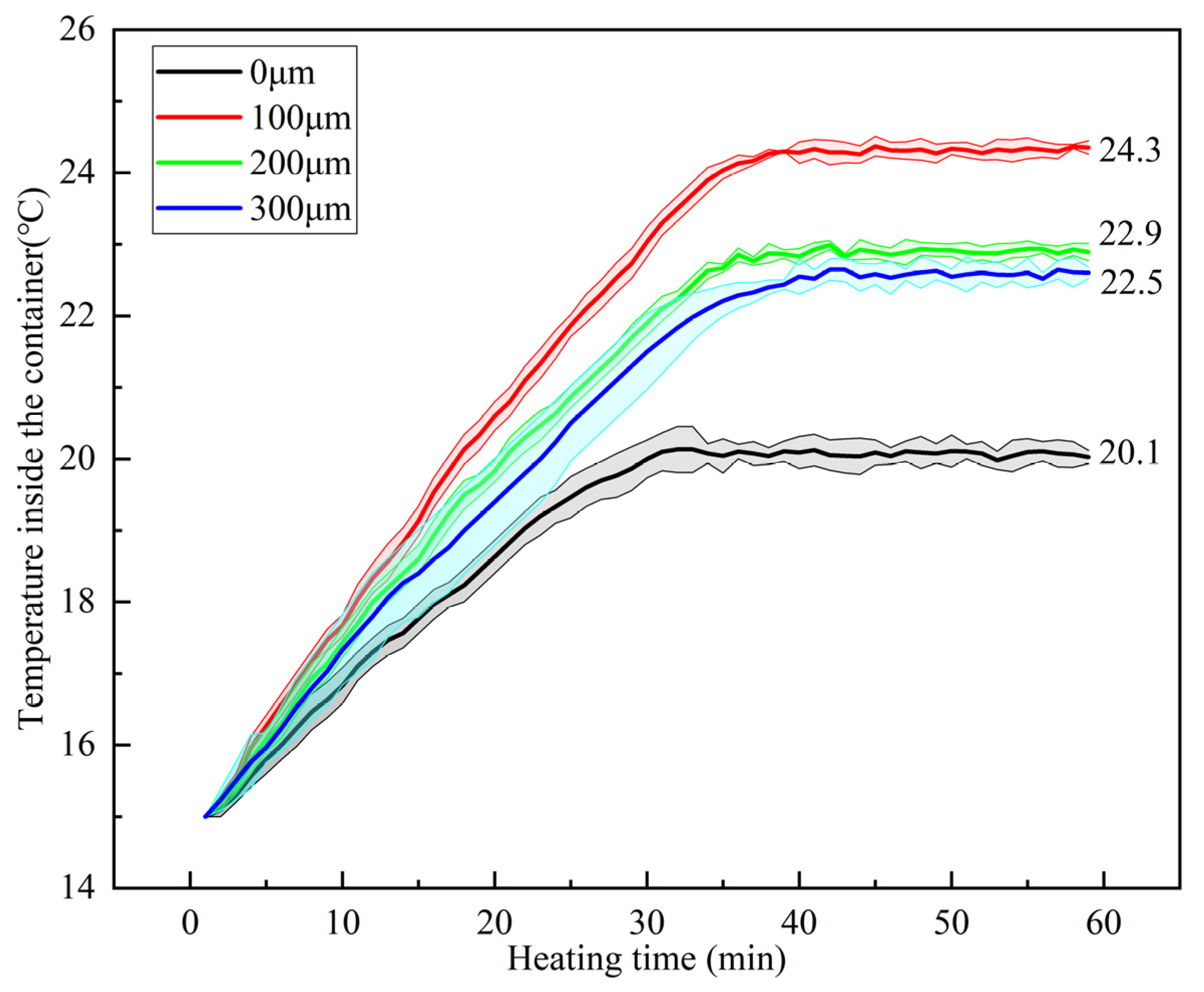
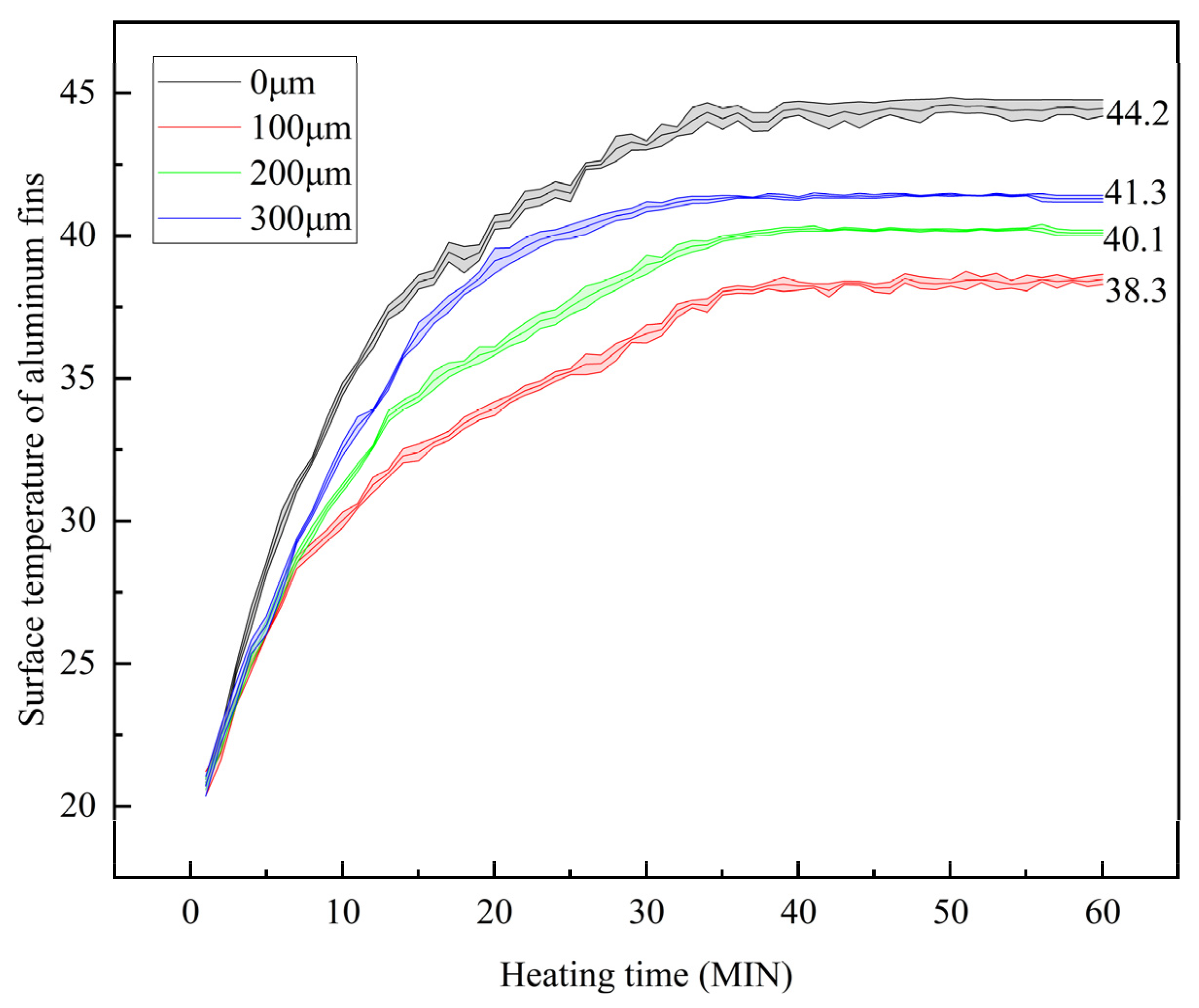
4.2.1. Analysis of Coating Thickness Test Results

Graphene coatings of different thicknesses were sprayed on the exterior of the aluminum alloy fin sheath of the heating cable using a spray gun. The initial temperature T0 in the insulation container was set to 15 °C, and the temperature TNi-Cr of the nickel–chromium alloy wire was set to 70 °C. The temperature Ts on the inner wall of the container and the surface temperature Tl of the aluminum fin of the heating cable change with heating time under different coating thicknesses, as shown in Figure 5 and Figure 6.
Figure 5 and Figure 6 demonstrate the thermal performance of heating cables with varying graphene coating thicknesses. For the uncoated control group, the container’s inner wall temperature increased from 15 °C to 20.1 ± 0.3 °C over 40 min (ΔT = 5.1 °C), exhibiting non-uniform heating rates, with the aluminum fin surface temperature stabilizing at 44.3 ± 0.3 °C, indicating significant heat retention within the fin sheath.
With a 100 μm coating, the container temperature rose uniformly from 15 °C to 24.3 ± 0.3 °C (ΔT = 9.3 °C) within 40 min, accompanied by a stabilized fin surface temperature of 38.3 °C, confirming enhanced heat transfer to the container. At 200 μm thickness, the container temperature reached 22.9 ± 0.3 °C (ΔT = 7.9 °C) over the same duration, with a fin surface temperature of 40.1 °C, reflecting a 14.6% reduction in heat transfer efficiency compared to the 100 μm case. For the 300 μm coating, the container temperature attained 22.5 ± 0.3 °C (ΔT = 7.5 °C) in 45 min, with a fin surface temperature of 41.2 °C, demonstrating comparable efficiency to the 200 μm configuration despite prolonged equilibration.
Experimental data align with numerical simulations: thicker coatings prolong thermal equilibrium times and reduce the maximum attainable container temperature due to increased thermal resistance. The fin surface temperature inversely correlates with coating thickness, rising from 38.3 ± 0.3 °C (100 μm) to 41.2 ± 0.3 °C (300 μm). Container temperature profiles further validate the proportional relationship between coating thickness and overall thermal resistance.

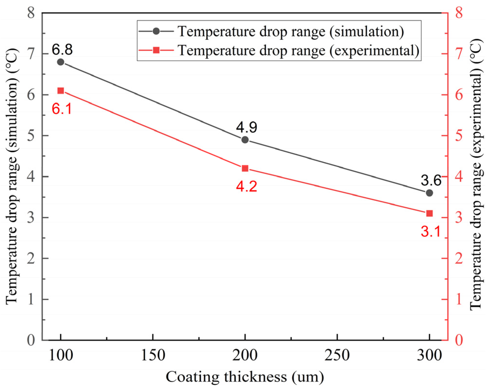
4.2.2. Correlation Between Simulation Value and Experimental Value of Coating Thickness

The influence of graphene coating thickness on heat dissipation was investigated numerically using a control model (uncoated cable) and Fluent’s Shell Conduction method to apply coatings (1 W/(m·K) thermal conductivity, thickness-dependent emissivity) on aluminum fin sheaths. The ambient temperature was maintained at 5 °C. Figure 7 illustrates the post-convergence temperature and heat flux distributions for different coating thicknesses. Simulations confirm experimental observations: thicker coatings reduce heat flux densities while increasing fin surface temperatures, consistent with the thermal resistance trends identified in experimental trials.
As shown in Figure 7, by spraying graphene coatings of different thicknesses on the aluminum fins of the heating cable, as coating thickness increased from 20 μm to 100 μm, the aluminum fin surface temperature decreased by 11%, and the overall heat flux increased by 26.7%. However, when the coating thickness increased from 100 μm to 300 μm, the aluminum fin surface temperature rose gradually, and the overall heat flux decreased gradually. This indicates that when coating thickness exceeds 100 μm, the heat dissipation capability begins to decline. It is also evident that at a coating thickness of 100 μm, the heat dissipation capability reaches its optimum. Below this thickness, the enhancement effect is more pronounced, but gradually decreases with further thickness reduction. This further confirms that the optimal heat dissipation capability occurs at a coating thickness of 100 μm.
As shown in Figure 8, the temperature difference on the aluminum fin surface before and after heating at thicknesses of 100 μm, 200 μm, and 300 μm obtained from numerical simulations is compared with the corresponding experimentally obtained temperature differences. As the coating thickness increases, the temperature difference on the aluminum fin surface also changes. This trend is consistent with the predictions based on thermal conductivity in the theoretical model.
Secondly, the error between the experimental results and numerical simulation is less than 8.5%, indicating that the numerical model is reasonably accurate. The temperature fluctuation of nickel–chromium alloy wire leads to the difference between the experimental measurement value and the theoretical model result. In addition, the measurement error of the infrared temperature acquisition instrument itself may also have a certain impact on the experimental results.

4.2.3. Mechanism Analysis of Heat Dissipation Performance with Respect to Coating Thickness

The experimental measurements reveal that increasing the graphene coating thickness from 20 μm to 100 μm reduces the aluminum fin surface temperature from 44.3 °C to 38.3 °C, with a concurrent 26.7% enhancement in heat flux density. However, when the thickness exceeds the critical threshold (e.g., 200 μm and 300 μm), the temperature rises to 40.1 °C and 41.2 °C, respectively, while heat flux density decreases by 7.9% and 9.3%. This phenomenon is attributed to the dynamic equilibrium between the coating’s thermal resistance and conductive performance:
Graphene coatings exhibit pronounced thickness-dependent thermal characteristics. In the thin-coating regime (≤100 μm), superior thermal management is achieved with low thermal resistance (Ra), primarily due to continuous heat transfer networks formed by high-thermal-conductivity graphene (6–10 W/(m·K)). Thin-layer spraying ensures uniform particle dispersion, effectively suppressing agglomeration and associated defects such as pores and microcracks. Microscopically, well-dispersed graphene sheets establish intimate interfacial contact with the matrix, significantly enhancing phonon coupling efficiency and reducing interfacial thermal resistance at the aluminum fin/coating boundary. The dense structure facilitates efficient longitudinal heat transfer along the graphene network to the coating surface. Macroscopically, thermal accumulation at the fin is mitigated, enabling rapid energy dissipation through radiation (governed by the Stefan–Boltzmann law) and convection. Consequently, thickness imposes negligible constraints on heat dissipation efficiency, with performance dominated by graphene’s intrinsic conductivity and structural integrity.
Conversely, coatings exceeding 100 μm exhibit linear growth in Ra, elevating substrate temperatures. This degradation stems from deteriorated dispersion and proliferated structural defects: During curing of thick wet films, rapid solvent evaporation at the surface forms a dense shell, while delayed internal evaporation generates inward contraction stresses. These stresses synergize with gravitational sedimentation and strong interlayer van der Waals forces, driving irreversible agglomeration. Concurrently, compromised surfactant effectiveness in thick layers exacerbates particle clustering, creating graphene-rich and polymer-rich zones accompanied by micropores and microcracks that disrupt coating homogeneity.
Figure 9 shows the SEM morphology of the graphene coating surface. Figure a illustrates the pore morphology on the side of the graphene coating; Figure b shows the agglomeration phenomenon on the graphene coating surface; Figure c depicts the multi-pore morphology on the graphene coating surface; and Figure d shows the microcracks and fractures on the side of the graphene coating.
Microscopic thermal analysis identifies these defects as primary contributors to interfacial resistance. Heat transfer relies predominantly on phonon transport, where agglomerate boundaries, pores, and microcracks create multiple thermal barriers, as shown in the red square in the figure: Severe phonon scattering occurs at agglomerate/matrix interfaces due to lattice vibration mismatch, while air pockets within defects (thermal conductivity ≈ 0.026 W/(m·K)) virtually block phonon pathways. According to Fourier’s law (R = δ/λ), these interfaces exhibit extremely low equivalent thermal conductivity (λ_interface) despite minimal physical thickness (δ), resulting in dramatically increased thermal resistance (R). The collective impact of distributed high-resistance interfaces significantly degrades the coating’s effective thermal conductivity. Although surface emissivity may improve slightly, heat transfer efficiency to the surface plummets due to accumulated internal resistance, ultimately causing thermal energy accumulation and heat dissipation failure.
Numerical simulation further validates the aforementioned mechanism. The fluent temperature field distribution shows that when the coating thickness is 100 μm, the surface temperature distribution of aluminum fins is most uniform, with the peak heat flux concentrated on the outer surface of the coating, indicating optimal radiative cooling efficiency. At this point, radiation accounts for 63% of the total heat dissipation, dominating the cooling process. When the thickness increases to 300 μm, a significant temperature gradient appears within the coating, and the heat flux distribution becomes more dispersed. At this stage, thermal resistance becomes the limiting factor, leading to a decrease in conduction efficiency. Equations (3)–(5) indicates that the longer thermal path x in thick coatings weakens the heat transfer rate from aluminum fins to the coating surface.

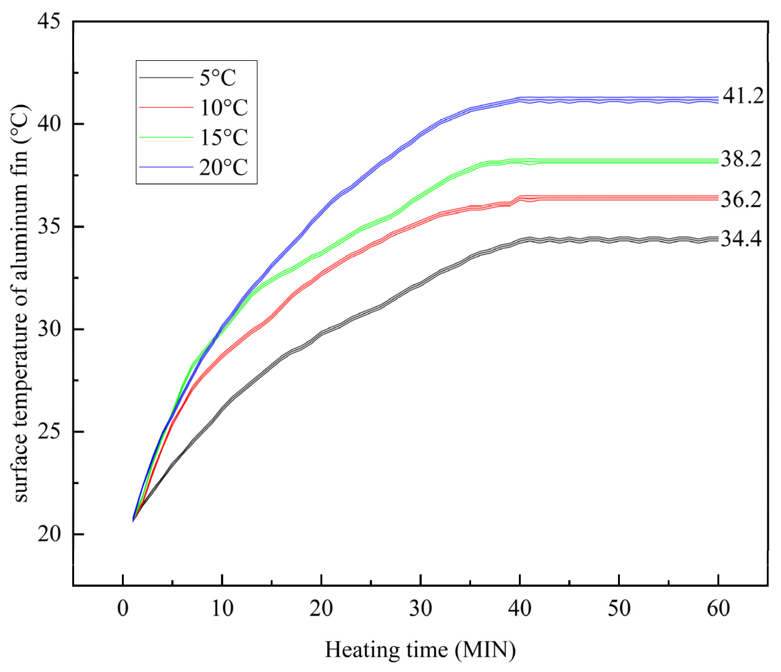
4.3. Effect of Ambient Temperature on Heating Cable Temperature-Rise Rate

4.3.1. Analysis of Ambient Temperature Experimental Results

The experiment involves the use of a heating cable with an aluminum fin surface coating thickness of 100 μm to study the temperature-rise rate of the heating cable under varying environmental temperatures. Three experiments were conducted at different initial temperatures: 5, 10, and 15 °C, as well as 20 °C. When the temperature of the nickel–chromium alloy heating wire is 70 °C, the changes in the temperature Ts of the inner wall of the container and the temperature Tl of the aluminum fin surface of the heating cable over time are shown in Figure 10 and Figure 11.
For the 100 μm graphene-coated heating cable, experimental results under varying ambient temperatures demonstrate distinct thermal behaviors. At an initial temperature of 5 °C, the container temperature increased uniformly from 5 °C to 18.6 ± 0.2 °C (ΔT = 13.5 °C) within 40 min, with the aluminum fin surface stabilizing at 34.4 ± 0.2 °C, indicating efficient heat dissipation.
When the initial temperature was elevated to 10 °C, the container temperature rose from 10 °C to 21.1 ± 0.2 °C (ΔT = 11.0 °C) over 40 min, exhibiting a consistent heating rate and a final fin surface temperature of 36.2 ± 0.2 °C.
At a 15 °C initial temperature, the container temperature climbed from 15 °C to 24.4 ± 0.2 °C (ΔT = 9.4 °C) in 40 min, with the fin surface reaching 38.2 °C and marginally extended equilibration time.
Under a 20 °C ambient condition, the container temperature increased unevenly from 20 °C to 27.4 ± 0.2 °C (ΔT = 7.4 °C) over 45 min, accompanied by a steeper temperature gradient and a higher fin surface temperature of 41.2 ± 0.2 °C.
Figure 10 and Figure 11 corroborate the numerical simulations: higher ambient temperatures prolong thermal equilibrium durations and reduce achievable temperature differentials. The maximum attainable container temperature inversely correlates with the initial ambient temperature, while fin surface temperatures exhibit a proportional increase. Heating intervals diminish as the initial temperature rises, reflecting reduced thermal efficiency due to diminished temperature gradients. These trends confirm that elevated ambient conditions amplify thermal resistance effects, thereby constraining the cable’s heat dissipation capacity.

4.3.2. Correlation Between Simulation Value and Experimental Value of Ambient Temperature

Fluent simulations were conducted to evaluate ambient temperature effects on the 100 μm graphene-coated heating cable. The numerical model employed a thermal conductivity of 1 W/(m·K), emissivity of 0.95, and ambient temperatures of 5 °C, 10 °C, 15 °C, and 20 °C. Figure 13 presents the converged three-dimensional temperature and heat flux distributions after simulation. The results demonstrate that as the ambient temperature rises from 0 °C to 15 °C, the temperature reduction range at the aluminum fin surface progressively narrows, while the overall heat flux of the heating cable declines systematically. This trend aligns with experimental observations, confirming that higher ambient temperatures exacerbate thermal resistance and limit heat dissipation capacity.
As can be seen from Figure 12, with the increase in ambient temperature, the surface temperature and heat flux of aluminum fins of the heating cable rise and fall steadily in a certain proportion, indicating that heat transfer becomes difficult, heat dissipation load increases, and heat flux decreases.
Figure 13 shows the relationship between the optimal spray thickness of heating cables and the calculated temperature difference. The lower the ambient temperature, the greater the impact of coating thickness. This is because under low-temperature conditions, radiative heat dissipation plays a dominant role in the overall heat dissipation process of heating cables, significantly higher than natural convection heat dissipation. An increase in coating thickness enhances surface smoothness and emissivity, thereby increasing radiative heat dissipation and ultimately leading to an increase in total heat dissipation. However, as the ambient temperature rises, the proportion of radiative heat dissipation in the total heat dissipation gradually decreases, until natural convection heat dissipation becomes dominant. In this case, with the increase in coating thickness, thermal resistance also increases, which can lower the surface temperature of aluminum fins and reduce the effectiveness of natural convection heat dissipation. Therefore, in high-temperature environments, the impact of coating thickness on heat dissipation is relatively reduced.
When using the same coating thickness, the numerical error in the surface temperature of aluminum fins obtained through experiments and numerical simulations is less than 20% over the initial temperature drop range, indicating good agreement between the surface numerical model and experimental results. The main reason for the error lies in the assumption that the coating thickness of the heating cable is uniform in the numerical model, whereas the actual coating thickness is influenced by the spraying equipment and is not uniform, leading to fluctuations between experimental and numerical results. Additionally, randomly selecting test positions during the calculation of the surface temperature drop range of aluminum fins can also introduce errors.

4.3.3. Analysis of the Mechanism of Different Heating Cable Heat Dissipation Efficiency in Different Ambient Temperatures

The mechanism of influence by different environmental temperatures is mainly divided into two types.
One is the weakening of temperature difference driving force: according to Formulas (3) and (4) and the radiation law Formulas (3)–(6), heat dissipation efficiency is directly related to the temperature difference (ΔT = T1 − T0) between the surface temperature of aluminum fins and the ambient temperature. When T0 increases, ΔT decreases, leading to a significant reduction in both convective and radiative heat dissipation driving forces. The other thermal conduction path is obstructed: an increase in ambient temperature leads to an increase in the heat capacity of the surrounding air, which weakens the heat transfer rate from aluminum fins to the environment. Formula (3) indicates that in high-temperature environments, the heat exchange efficiency between aluminum fins and air decreases, causing heat to accumulate on the fin surface.
In summary, ambient temperature is a crucial factor to consider for the heat dissipation of heating cables. High temperatures can lead to reduced heat dissipation efficiency, coating quality, and cable lifespan. In practical applications, it is essential to determine how environmental temperature affects heating cables to ensure their proper operation.

5. Conclusions

This study proposes a thermal optimization strategy for graphene-coated heating cables, systematically revealing the nonlinear effects of coating position, thickness, and ambient temperature on heat dissipation performance through integrated numerical and experimental analyses.
(1) The experimental results demonstrate that applying graphene coatings to aluminum fin sheath exteriors increases heat flux by 26.67%, enhancing radiative heat dissipation, reduces fin surface temperature to 41.5 °C, and improves temperature-rise efficiency by approximately 50%.
(2) An optimal balance between thermal resistance and conductivity occurs at a coating thickness of 100 μm, achieving a 26.7% increase in heat flux. Beyond 100 μm, increased interfacial thermal resistance causes heat accumulation, reducing heat flux by 7.9%–9.3%. Simulations confirm that graphene’s high thermal conductivity dominates heat transfer for thicknesses ≤ 100 μm, while thermal resistance becomes the limiting factor for thicknesses > 100 μm.
(3) Elevated ambient temperatures significantly suppress cooling performance. When the initial ambient temperature increases from 5 °C to 20 °C, the fin surface temperature increases by 6.1 °C, the achievable container temperature rise decreases by 45.2%, and heat flux decreases by 32.4%. Mechanism analysis identifies weakened thermal differential driving forces (ΔT = T1 − T0) and compromised heat conduction pathways as primary causes.
(4) Numerical–experimental discrepancies remain below 8.5%, validating model reliability. The optimal parameters for graphene coating application are determined as 100 μm thickness applied to the outer 1.5 mm layer of aluminum fin sheaths, providing theoretical foundations for enhancing low-temperature radiant heating system efficiency.
Although optimization parameters for the graphene coating (100 μm thick on aluminum fins) have been established, key challenges persist for industrial applications, including coating adhesion stability, long-term durability, and cost-effectiveness. The difference in thermal expansion coefficients between the aluminum fins and the resin matrix generates cyclic mechanical stress, leading to interface delamination in coatings exceeding 100 μm in thickness. Under continuous operation at 70 °C, the risk of resin oxidation increases, and mechanical wear may reduce the material’s luminescence efficiency. A high graphene content (25%–35%) increases the material cost fivefold compared to traditional coatings. Stress induced by solvent evaporation during thick-layer deposition may cause irreversible aggregation. To overcome these challenges, subsequent research will develop ultrasonic spraying technology capable of depositing coatings from 100 μm to nanoscale for application on nickel–chromium alloy heating wires (hot cores).

Author Contributions

Conceptualization, Z.C.; Data curation, C.X. and T.S.; Formal analysis, C.X.; Funding acquisition, Z.C.; Investigation, F.Z.; Project administration, C.X. and T.S.; Supervision, F.Z.; Writing—original draft, Z.C.; Writing—review and editing, F.Z. All authors have read and agreed to the published version of the manuscript.

Funding

This research was funded by the National Natural Science Foundation of China grant number No. 51705463 and Zhejiang Provincial Natural Science Foundation of China grant number No. LTGS23E050001.

Institutional Review Board Statement

Not applicable.

Informed Consent Statement

Not applicable.

Data Availability Statement

Data are contained within the article.

Conflicts of Interest

The authors declare no conflicts of interest.

References

  1. Wang, Y.; Zhan, G.; Mao, W.; Lai, Y.; Luo, Y.; Liu, P. Numerical Simulation and Experimental Verification of Cu\Ni Dissimilar Metal Wire Deep Penetration Brazing. In Proceedings of the 2020 5th International Conference on Smart Grid and Electrical Automation (ICSGEA), Zhangjiajie, China, 13–14 June 2020; pp. 125–128. [Google Scholar] [CrossRef]
  2. Kim, J.-C.; Wi, J.-H.; Ri, N.-C.; Ri, S.-I. Thermal Conductivity of Graphene/Graphane/Graphene Heterostructure Nanoribbons: Non-Equilibrium Molecular Dynamics Simulations. Solid State Commun. 2021, 328, 114249. [Google Scholar] [CrossRef]
  3. Pyun, K.R.; Ko, S.H. Graphene as a Material for Energy Generation and Control: Recent Progress in the Control of Graphene Thermal Conductivity by Graphene Defect Engineering. Mater. Today Energy 2019, 12, 431–442. [Google Scholar] [CrossRef]
  4. Zhang, S.; Wang, H.; Liu, J.; Bao, C. Measuring the Specific Surface Area of Monolayer Graphene Oxide in Water. Mater. Lett. 2020, 261, 127098. [Google Scholar] [CrossRef]
  5. Aacharya, A.; Koirala, R.; Khanal, S.; Baral, B. Comparative Analysis of Radiant and Radiator Heating System for a Residential Building. IOP Conf. Ser. Mater. Sci. Eng. 2023, 1279, 012001. [Google Scholar] [CrossRef]
  6. Guan, Y.; Cui, H.; Fei, J. Study on Optimization of Copper to Aluminum for Locomotive Finned Tube Radiator. Energies 2023, 16, 2130. [Google Scholar] [CrossRef]
  7. Wang, F.; Li, Z.; Pang, D.; Li, Z.; Zhao, X.; Cheng, X.; Liu, M.; Zhang, Y.; Guo, W. Enhancing Heat Transfer of Photovolta-ic Panels with Fins. Int. J. Energy Res. 2024, 2024, 5180627. [Google Scholar] [CrossRef]
  8. Guan, Y.; Cui, H.; Li, M. Numerical Simulation Study on Air-Side of Diesel Locomotive Finned Tube Double Channel Radiator. J. Phys. Conf. Ser. 2021, 1746, 012048. [Google Scholar] [CrossRef]
  9. Majmader, F.B.; Hasan, M.J. Thermal Enhancement and Entropy Generation of an Air-Cooled 3D Radiator with Modified Fin Geometry and Perforation: A Numerical Study. Case Stud. Therm. Eng. 2023, 52, 103671. [Google Scholar] [CrossRef]
  10. Tran, N.; Wang, C.-C. Optimization of the Airside Thermal Performance of Mini-Channel-Flat-Tube Radiators by Using Composite Straight-and-Louvered Fins. Int. J. Heat Mass Transf. 2020, 160, 120163. [Google Scholar] [CrossRef]
  11. Habibian, S.H.; Abolmaali, A.M.; Afshin, H. Numerical Investigation of the Effects of Fin Shape, Antifreeze and Nanoparticles on the Performance of Compact Finned-Tube Heat Exchangers for Automobile Radiator. Appl. Therm. Eng. 2018, 133, 248–260. [Google Scholar] [CrossRef]
  12. Lipnický, M.; Brodnianská, Z.; Kotšmíd, S. Research of Geometrically Distinct Automobile Radiators in Terms of Thermal-Hydraulic Characteristics. Appl. Therm. Eng. 2023, 232, 121035. [Google Scholar] [CrossRef]
  13. Li, X.; Chen, Y.; Mo, S.; Jia, L.; Shao, X. Effect of Surface Modification on the Stability and Thermal Conductivity of Water-Based SiO2-Coated Graphene Nanofluid. Thermochim. Acta 2014, 595, 6–10. [Google Scholar] [CrossRef]
  14. Zhu, F.; Kan, Y.; Tang, K.; Liu, S. Investigation of Thermal Properties of Ni-Coated Graphene Nanoribbons Based on Molecular Dynamics Methods. J. Electron. Mater. 2017, 46, 4733–4739. [Google Scholar] [CrossRef]
  15. Manasoglu, G.; Celen, R.; Kanik, M.; Ulcay, Y. An Investigation on the Thermal and Solar Properties of Graphene-Coated Polyester Fabrics. Coatings 2021, 11, 125. [Google Scholar] [CrossRef]
  16. Wei, B.; Yang, N.; Tian, M.; Qu, L.; Zhu, S. Effect of Coating Methods on Thermal Conductivity of Graphene-Coated Fabrics for Welding Protective Clothing. Mater. Lett. 2022, 314, 131787. [Google Scholar] [CrossRef]
  17. Dong, P.; Long, C.; Peng, Y.; Peng, X.; Guo, F. Effect of coatings on thermal conductivity and tribological properties of aluminum foam/polyoxymethylene interpenetrating composites. J. Mater. Sci. 2019, 54, 13135–13146. [Google Scholar] [CrossRef]
  18. Almonti, D.; Ucciardello, N. Improvement of thermal properties of micro head engine electroplated by graphene: Experimental and thermal simulation. Mater. Manuf. Process. 2019, 34, 1612–1619. [Google Scholar] [CrossRef]
  19. Lv, F.; Qin, M.; Zhang, F.; Yu, H.; Gao, L.; Lv, P.; Wei, W.; Feng, Y.; Feng, W. High Cross-Plane Thermally Conductive Hierarchical Composite Using Graphene-Coated Vertically Aligned Carbon Nanotubes/Graphite. Carbon 2019, 149, 281–289. [Google Scholar] [CrossRef]
  20. Zhang, H.; Fan, D. Improving Heat Dissipation and Temperature Uniformity in Radiative Cooling Coating. Energy Technol. 2020, 8, 1901362. [Google Scholar] [CrossRef]
  21. Perović, B.; Klimenta, D.; Tasić, D.; Raičević, N.; Milovanović, M.; Tomović, M.; Vukašinović, J. Increasing the Ampacity of Underground Cable Lines by Optimising the Thermal Environment and Design Parameters for Cable Crossings. IET Gener. Transm. Distrib. 2022, 11, 2309–2318. [Google Scholar] [CrossRef]
  22. Masnicki, R.; Mindykowski, J.; Palczynska, B. The Laboratory Stand for the Evaluation of Heat Dissipation from the Power Cable in a Casing Pipe. In Proceedings of the 2022 IEEE International Conference on Environment and Electrical Engineering and 2022 IEEE Industrial and Commercial Power Systems Europe (EEEIC/I&CPS Europe), Prague, Czech Republic, 28 June–1 July 2022; pp. 1–6. [Google Scholar] [CrossRef]
  23. Cvetković, D.; Nešović, A. Impact of heat source at radiant electric heating panel. Energy Build. 2021, 239, 110843. [Google Scholar] [CrossRef]
  24. Lu, X.; Cai, L.; Jia, Q.; Wang, J.; Sun, M.; Wang, L. Numerical Analysis of Cable Heat Output for Renewable Energy Transmission Lines. In Proceedings of the 2024 7th International Conference on Energy, Electrical and Power Engineering (CEEPE), Yangzhou, China, 26–28 April 2024; pp. 1500–1504. [Google Scholar] [CrossRef]
  25. Nie, Y.; Chen, D.; Zheng, S.; Xu, X.; Wang, X.; Wu, Z. Simulation and Calculation of Temperature Field and Current-Carrying Capacity of Power Cables under Different Laying Methods. Energies 2024, 17, 4611. [Google Scholar] [CrossRef]
  26. Xie, H.; Zhang, J.-q.; Liu, Y.-f.; Zhang, B.-s.; Wang, L.-f.; Fan, M.-h. Study on insulation failure time and failure temperature of the aged cables under external heating. Procedia Eng. 2018, 211, 1012–1017. [Google Scholar] [CrossRef]
  27. Lei, J.; Xiao, S.; Liu, Y.; Deng, X.; Tian, A.; Dong, l. Multi-Objective Optimisation of Heat Transfer and Structural Strength of Aero-Piston Air-Cooled Engine Cylinder Based on Orthogonal Test. Therm. Sci. Eng. Prog. 2024, 50, 102500. [Google Scholar] [CrossRef]
  28. Mallick, M.; Arunachalam, N. Effects of Electrophoretic Deposited Graphene Coating Thickness on the Corrosion and Wear Behaviors of Commercially Pure Titanium. Surf. Coat. Technol. 2022, 450, 128946. [Google Scholar] [CrossRef]
  29. Lanza, M.; Wang, Y.; Sun, H.; Tong, Y.; Duan, H. Morphology and performance of graphene layers on as-grown and transferred substrates. Acta Mech. 2014, 225, 1061–1073. [Google Scholar] [CrossRef]
  30. Fang, M.; Xiong, X.; Hao, Y.; Zhang, T.; Wang, H.; Cheng, H.-M.; Zeng, Y. Preparation of Highly Conductive Graphene-Coated Glass Fibers by Sol-Gel and Dip-Coating Method. J. Mater. Sci. Technol. 2019, 35, 1989–1995. [Google Scholar] [CrossRef]
  31. Zhang, H.; Ge, Y.; Pan, P.; Du, Y.; Fu, H.; Yan, M.; Li, P.; Long, H.; Zhang, C.; Cai, J.; et al. Suppression of Secondary Electron Emission on Oxygen-Free Copper Surface of Reduced Graphene Oxide Coatings Prepared by Electrophoretic Deposition. Appl. Surf. Sci. 2022, 603, 154490. [Google Scholar] [CrossRef]
  32. Ji, H.; Qiao, J.; Kang, N.; Wang, X.; Huang, J. Optimization of Hot Extrusion Process Parameters for 7075 Aluminum Alloy Rims Based on HyperXtrude. J. Mater. Res. Technol. 2023, 25, 4913–4928. [Google Scholar] [CrossRef]
  33. GB/T 1720-2020; Circle-Drawing Test of Coating Films. Standardization Administration of China: Beijing, China, 2020.
Figure 1. Schematic diagram of experimental device and numerical simulation model.
Coatings 15 00777 g001
Figure 2. Surface Characterization of Sprayed Graphene Coating. (a) Application Effect on Heating Cable, (b) Morphology, (c) Thickness Verification, and (d) Surface Quality Assessment.
Coatings 15 00777 g002
Figure 3. Temperature cloud image of heat dissipation of heating cable without coating.
Coatings 15 00777 g003
Figure 4. Temperature variation curves of the heating cable coated with graphene at different locations: (a) uncoated with graphene, (b) coated on the outside of the nickel–chromium heating wire (position 1), (c) coated on the outside of the XLPE insulation (position 2), and (d) coated on the outside of the aluminum fin sheath (position 3).
Coatings 15 00777 g004
Figure 5. Temperature evolution of the container inner wall for different coating thicknesses.
Coatings 15 00777 g005
Figure 6. Evolution of aluminum fin surface temperature for different coating thicknesses.
Coatings 15 00777 g006
Figure 7. Temperature and heat flux distributions for numerical models of graphene coatings with different thicknesses after FLUENT solution convergence.
Coatings 15 00777 g007
Figure 8. Comparison of temperature differences.
Coatings 15 00777 g008
Figure 9. Surface morphology of graphene coating. (a) Microstructure; (b) Reunion morphology (c) Micro-pore morphology (d) Microcrack and fracture morphology.
Coatings 15 00777 g009
Figure 10. Temperature variation law of inner wall surface of container under different ambient temperatures.
Coatings 15 00777 g010
Figure 11. The variation law of aluminum fin surface temperature under different ambient temperatures.
Coatings 15 00777 g011
Figure 12. The heat dissipation of heating cables varies with the ambient temperature.
Coatings 15 00777 g012
Figure 13. The variation of coating thickness at different ambient temperatures.
Coatings 15 00777 g013
Table 1. Thermal conductivity of coating with different thickness.
Coating Thickness/μmThermal Conductivity/W/(m·K)EmissivityAdhesion Grade
500.6320.791
1000.8150.951
2000.7460.921
3000.7290.831
Table 2. Performance index comparison table of heating cables.
Coating Thickness/μmEnvironmental Temperature (°C)Heat Flux (W/m2·K)Aluminum Fin Surface Temperature (°C)Container Temperature Rise ΔT (°C)
01512,00044.35.1
1001515,20038.99.3
2001513,90040.17.9
3001513,50041.27.5
100518,50034.413.5
1002012,70040.57.3
Table 3. Grid Convergence Analysis Results.
Mesh Size (mm)Mesh Count (Million)Tfin (°C)q″ (W/m2·K)GCI (%)
0.50.852.0 ± 1.210,500 ± 2007.3
0.21.250.1 ± 0.811,200 ± 1504.7
0.13.048.3 ± 0.512,000 ± 1001.2
0.056.548.1 ± 0.312,050 ± 80-
Disclaimer/Publisher’s Note: The statements, opinions and data contained in all publications are solely those of the individual author(s) and contributor(s) and not of MDPI and/or the editor(s). MDPI and/or the editor(s) disclaim responsibility for any injury to people or property resulting from any ideas, methods, instructions or products referred to in the content.

