Article

Preparation of CF-NiO-PANI Electrodes and Study on the Efficiency of MFC in Recovering Potato Starch Wastewater

1
School of Food Engineering, Harbin University of Commerce, Harbin 150028, China
2
Central&Southern China Municipal Engineering Design and Research Institute Co., Ltd., Kunming 430010, China
3
Ecological Environment Monitoring Station of Lincang Ecological Environment Bureau, Lincang 677000, China
4
School of Light Industry, Harbin University of Commerce, Harbin 150028, China
*
Authors to whom correspondence should be addressed.
These authors contributed equally to this work.
Coatings 2025, 15(7), 776; https://doi.org/10.3390/coatings15070776
Submission received: 2 June 2025 / Revised: 25 June 2025 / Accepted: 29 June 2025 / Published: 30 June 2025
(This article belongs to the Section Environmental Aspects in Colloid and Interface Science)

Abstract

Microbial Fuel Cell (MFC) is a novel bioelectrochemical system that catalyzes the oxidation of chemical energy in organic waste and converts it directly into electrical energy through the attachment and growth of electroactive microorganisms on the electrode surface. This technology realizes the synergistic effect of waste treatment and renewable energy production. A CF-NiO-PANI capacitor composite anode was prepared by loading polyaniline on a CF-NiO electrode to improve the capacitance of a CF electrode. The electrochemical characteristics of the composite anode were evaluated using cyclic voltammetry (CV) and electrochemical impedance spectroscopy (EIS), and the electrode materials were analyzed comprehensively by scanning electron microscopy (SEM), energy diffusion spectrometer (EDS), and Fourier transform infrared spectroscopy (FTIR). MFC system based on CF-NiO-PANI composite anode showed excellent energy conversion efficiency in potato starch wastewater treatment, and its maximum power density increased to 0.4 W/m3, which was 300% higher than that of the traditional CF anode. In the standard charge–discharge test (C1000/D1000), the charge storage capacity of the composite anode reached 2607.06 C/m2, which was higher than that of the CF anode (348.77 C/m2). Microbial community analysis revealed that the CF-NiO-PANI anode surface formed a highly efficient electroactive biofilm dominated by electrogenic bacteria (accounting for 47.01%), confirming its excellent electron transfer ability. The development of this innovative capacitance-catalytic dual-function anode material provides a new technical path for the synergistic optimization of wastewater treatment and energy recovery in MFC systems.

1. Introduction

Potato is an annual crop of the Solanaceae. It originated in the Andes of South America and was introduced into China in the 16th century [1,2,3]. As an important rotation crop, it is often planted with corn, wheat, and other gramineous crops. Its tubers are rich in starch (15%–20%), protein (2%–3%), vitamin C, and potassium [4,5,6]. The annual output of potatoes in China exceeds 100 million tons, ranking first in the world. Since the beginning of the 20th century, potatoes have been made into potato chips, chips, starch, and whole flour due to their excellent processing characteristics [7,8].
Potato vermicelli is a traditional food in northern China, mainly produced in Gansu, Inner Mongolia, and other places [9,10]. The production adopts a precipitation separation process, producing 8–12 tons of wastewater per ton of starch [11]. The wastewater contains 0.8% protein and a large amount of sugar, and the existing resource utilization rate is not high [12]. Compared with corn starch wastewater, the recovery research of potato starch wastewater is relatively lacking, which has important research value [13,14].
In order to meet the demand for potato starch wastewater treatment, microbial fuel cell (MFC) technology has shown unique advantages compared with traditional methods such as physical separation and biodegradation. MFC is an innovative bioelectrochemical technology that converts organic waste into electrical energy by electroactive microorganisms while simultaneously purifying wastewater [15,16,17]. A two-chamber MFC consists of an anode chamber, a cathode chamber, a proton exchange membrane, and an external circuit. Electrogenic microorganism (e.g., Geobacter) oxidizes organic matter at the anode; the electrons generated are transferred through the external circuit; protons migrate through the membrane; and they finally react with oxygen at the cathode to produce water, with an energy conversion efficiency of 40%–60% [18,19,20]. The electrode material must meet the conductivity (<0.1 Ω·cm), large specific surface area (>1000 m2/g), and biocompatibility requirements. Carbon-based materials (carbon felt, graphene, etc.) are widely used due to their cost advantages [21,22]. NiO/carbon felt anode can improve the maximum power density, electricity storage, and electricity generation of MFC compared with pure carbon felt anode [23,24], while composite modified materials (such as polyaniline modified carbon felt) can improve the power density two to three times, which is the focus of current research [25,26]. Polyaniline and NiO, which are more obvious in improving CF performance, can be tested. After 60 min of charge and discharge, the total charge of the CF-NiO anode is 6663.25 C/m2, while the CF-PANI anode accumulates 13,930.1 C/m2 in only 20 min; therefore, it can be concluded that polyaniline improves CF performance more than NiO [27]. If the two are combined, the performance of MFC in all aspects will be further improved.
NiO-supported carbon felt electrode can be modified by NiO nanoparticles in MFC, which can significantly improve the electron transfer rate of electrodes and increase the number of microorganisms attached [28]. As a typical conductive polymer, polyaniline (PANI) can be functionalized by electrochemical polymerization or chemical oxidation [29,30]. Carbon felt/PANI composite can significantly improve the electron transfer efficiency of the anode. CF-NiO-PANI anode cells can be obtained by combining the two, and their maximum power density, storage capacity, and power generation are about two times that of CF-NiO anode cells [31,32] and about three to five times that of CF anode cells. For similar experiments, such as that by Li et al. [33], using PANI and poly (aniline-co-o-aminophenol) (PAOA) two conductive polymer materials to modify carbon felt anode, the maximum power density of MFC is 0.0238 W/m2, while the CF-NiO-PANI electrode prepared in this experiment can reach 0.4 W/m2 as an MFC anode. Compared with traditional methods for removing organic matter from wastewater, MFC can recover energy without secondary pollution to the environment [34].
In this paper, a new microbial fuel cell technology is adopted to achieve the dual goals of wastewater treatment and synchronous energy production through anode modification [35,36]. Electroactive microorganisms in the anode region of MFC can decompose starch residues, proteins, and amino acids in potato starch wastewater, oxidize them into CO2 and water, and release electrons to the anode to generate current. The anode of MFC directly “collects” electrons from organic waste through microbial metabolism, and the cathode collaborates with pollutants through a reduction reaction. The electrode is both a waste conversion site and a medium for energy recovery, achieving the dual goals of wastewater treatment and recycling [37]. The electrode interface characteristics are innovatively optimized in the experiment, and the electron transfer efficiency and energy conversion rate of the system are significantly improved [38]. From the perspective of environmental benefits, the process realizes a green and low-carbon wastewater treatment mode. From the technical point of view, although the economic advantage has not yet been highlighted in the short term, breakthrough progress has been made in energy recovery efficiency [39,40,41]. This paper not only provides a new idea for the resource treatment of organic wastewater, but also lays an important theoretical foundation for the subsequent large-scale application of electrode modification parameters and process optimization.

2. Preparation and Methods

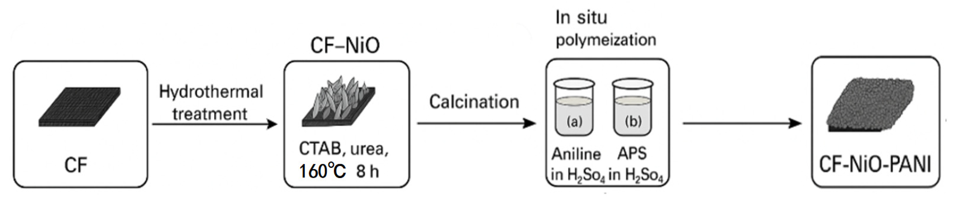
2.1. Preparation of the CF-NiO-PANI Electrode

Figure 1 is a schematic diagram of the chemical reaction of CF-NiO-PANI electrode preparation. As shown in the figure, the CF-NiO-PANI electrode was prepared by in situ polymerization of PANI on the CF-NiO electrode by chemical method. The CF-NiO electrode was prepared by in situ growth of NiO on the CF substrate by chemical method. The CF-NiO electrode was prepared by dissolving 0.819 g cetyltrimethylammonium bromide (CTAB, analytical grade, Tianjin Fuyu Fine Chemical Co., Ltd., Tianjin, China) in 60 mL distilled water and stirring for 15 min. Then, 0.45 g urea (H2NCONH2, analytical grade, Tianjin Zhiyuan Chemical Reagent Co., Ltd., Tianjin, China) and 0.713 g NiCl2·6H2O (NiCl2·6H2O, analytical grade, Tianjin Fuyu Fine Chemical Co., Ltd., Tianjin, China) were added to the above solution and stirred for 30 min. The solution was transferred into the inner vessel (100 mL capacity) of the hydrothermal reactor, put into carbon felt, and heated at 160 °C for 8 h. Flaky Ni(OH)2 gradually grew on the blank CF. After washing and drying, the nickel oxide precursor-loaded carbon felt was placed in a crucible and calcined at 250 °C for 2 h. The CF-NiO-PANI electrode was prepared. First, a 1.5 mol/L sulfuric acid solution was prepared for subsequent use. Then, 10 mL of sulfuric acid solution was measured, and aniline (C6H7N, analytical grade, Tianjin FuChen Chemical Reagent Co., Ltd., Tianjin, China) was added at room temperature and stirred for 30 min. The obtained solution was recorded as solution (a). Then, 7 mL sulfuric acid solution was taken, ammonium persulfate (APS, analytical grade, Shanghai EasyEn Chemical Technology Co., Ltd., Shanghai, China) was added at room temperature, it was stirred for 30 min, and the obtained solution was recorded as solution (b). Under the condition of ice water bath, the CF-NiO electrode was completely immersed in solution (a), and solution (b) was slowly dropped into solution (a) at the speed of 6 drops/min; after complete dropwise addition, the in situ polymerization was allowed to proceed for an additional 8 h, with the entire reaction process maintained under ice water bath conditions, and the reaction process was carried out under the condition of ice water bath. Finally, the polymerized electrode was washed repeatedly with distilled water and anhydrous ethanol (C2H5OH, analytical grade, Tianjin Tianli Chemical Reagent Co., Ltd., Tianjin, China), and then dried, and the CF-NiO-PANI electrode was obtained.

2.2. Electrodes’ Electrochemical Tests

The electrochemical measurements were carried out with a three-electrode system, using 0.25 mol/L Na2SO4 solution as the electrolyte, a prepared electrode as the working electrode, a saturated calomel electrode as the reference electrode, and a platinum electrode as the counter electrode. Cyclic voltammetry (CV), AC impedance (EIS), and chronopotentiometry (CP) were carried out with a CHI760E electrochemical workstation (Huachen, Shanghai China), and the data were recorded. CV can reflect the characteristics of electron transfer, interface interaction, and reaction reversibility. The CV test for this experiment uses a sweep rate of 20 mV/s. EIS measures the impedance response of the electrode system by applying a sinusoidal disturbance signal of 5 mV amplitude (frequency range 0.1–10 Hz) at an open circuit potential. CP evaluates electrode performance by applying a constant current (set at 5 mA for this experiment) and recording a voltage–time curve, with the test termination potential set at 0.6 V.

2.3. CF-NiO-PANI Electrode Characterization

The samples were characterized by SEM, FTIR, and EDS. The samples were fixed with conductive glue and sprayed with gold. The surface structure characteristics were observed under 1000× and 5000× magnification, respectively. The samples were characterized by a Hitachi SU5000 scanning electron microscope. The molecular structure of the samples was analyzed by FTIR. The dried samples were mixed with KBr and ground. The samples were characterized by a ThermoIS5 spectrometer (Thermo Fisher Scientific, Waltham, MA, USA). EDS is used to analyze the elemental composition of the sample. The high-energy electron beam excites the sample atoms to produce characteristic X-rays, and the elemental species and content are detected by the Oxford ULTIMATELY MAX40 spectrometer (Oxford Instruments plc., Oxfordshire, UK). The measurement is completed simultaneously with SEM.

2.4. MFC Construction and Performance Testing

2.4.1. Pretreatment of Carbon Felt

Carbon felt with a thickness of 3 mm was cut into square pieces of 2 cm × 2 cm, and then the following treatment steps were carried out: Carbon felt was immersed in absolute ethanol, ultrasonic cleaning was carried out for 1 h to remove grease on the surface, and then the carbon felt was washed with distilled water. Next, the carbon felt was immersed in 5% hydrochloric acid solution for 3 h, washed with distilled water, and finally dried in an oven at 60 °C as a spare material for subsequent experiments.

2.4.2. Proton Exchange Membrane Pretreatment

First, the membrane material was cut into 5 cm × 5 cm squares. Then, it was treated in a distilled water bath at 80 °C for 1 h. Then, the membrane was immersed in 3% hydrogen peroxide solution and treated in a water bath at 80 °C for 1 h. Then, we changed to 0.5 M sulfuric acid solution and treated it in a water bath at 80 °C for 1 h. After treatment, the proton exchange membrane was rinsed with deionized water 3 times, each time for 1 h. The finally obtained proton exchange membrane was completely immersed in deionized water and stored for future use.

2.4.3. Start-Up of Microbial Fuel Cells

A two-chamber MFC system was constructed in this experiment. A glass reactor of equal volume was used. The anode and cathode chambers were separated by a proton exchange membrane. The prepared electrode was used as an anode, and the anolyte was composed of anaerobic mixed bacterial culture and potato starch wastewater (pH adjusted to 7.0). The electrodes were sealed with epoxy resin and connected with titanium wire. The cathode chamber contained 10 g/L K3[Fe(CN)6] solution, and the carbon rod was used as the cathode. The titanium wire was connected. The external resistance of 8 kΩ was used for microbial acclimation. The acclimation was considered to be completed by monitoring the anode potential until it was stable.

2.4.4. MFC Performance Testing

The CF-NiO-PANI anode was assembled into the MFC system, and the electricity generation performance of the modified anode was evaluated through the process of microbial degradation of organic matter in wastewater.
(1)
Polarization curve
Polarization curves were constructed to characterize system performance by measuring MFC potentials at different external resistances (0–9000 Ω).
(2)
Power density curve
The power density curve evaluates the power generation performance of MFC by characterizing the relationship between output power and current density, which was calculated based on the cell potential test data in (1).
(3)
Anodic polarization curve
Anodic polarization curves were obtained by characterizing the anode potential versus current density. The measurements were performed at MFC steady state operation by adjusting the external resistance of the varistor box from 0 to 9000 Ω, in combination with the determination of anode potential at a saturated calomel electrode.
(4)
MFC cyclic voltammetry test
The electrochemical activity of the MFC anode was studied by cyclic voltammetry using a CHI760E electrochemical workstation (Huachen), the anode as a working electrode, the cathode as a counter electrode, and a saturated calomel electrode as the reference electrode.
(5)
MFC AC impedance test
The CHI760E electrochemical workstation (Huachen) was used to carry out the EIS measurement. The MFC anode was used as a working electrode, a cathode as the counter electrode, and a saturated calomel electrode as the reference electrode to characterize the anode electron transfer characteristics.
(6)
Chronograph current test (CA)
The CA test was carried out with a CHI760E electrochemical workstation (Huachen), with an MFC anode as the working electrode, a cathode as the counter electrode, and a saturated calomel electrode as the reference electrode. Constant potential was applied during the test, and the current density–time curve was recorded to evaluate the charge–discharge performance of MFC.

2.5. MFC High-Throughput Sequencing

The standard method of Shanghai Sangong Biological Company was used to analyze the community structure of anolyte microorganisms. Firstly, gDNA was extracted using the Mag-Bind Soil DNA Kit (Omega Bio-tek, Norcross, GA, USA), the integrity was detected using agarose gel electrophoresis, and the concentration was determined using Qubit. Then, the PCR amplification region of 16SV3-V4 was selected, and the PCR amplification products were purified by agarose electrophoresis. Finally, the species diversity and relative abundance were analyzed by sequencing data.

3. Experimental Results and Discussion

3.1. The Characteristics of CF-NiO-PANI Electrode Structures

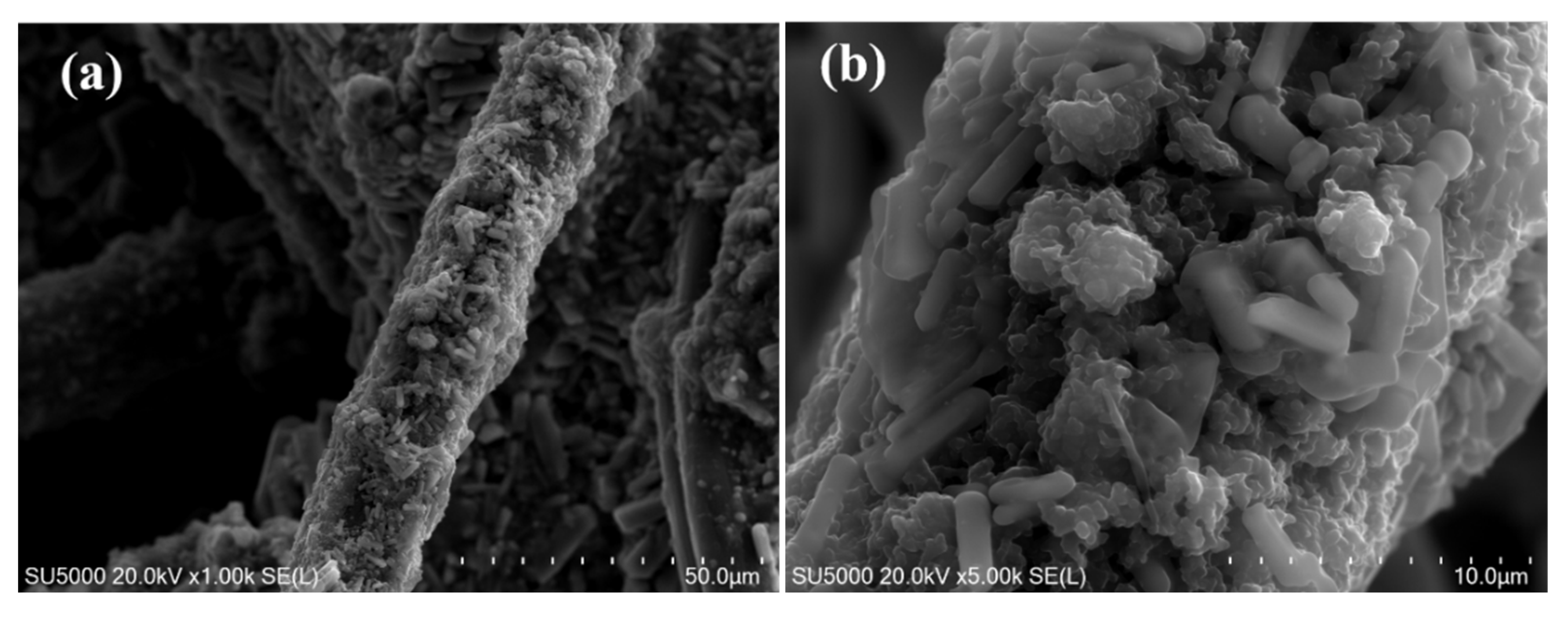
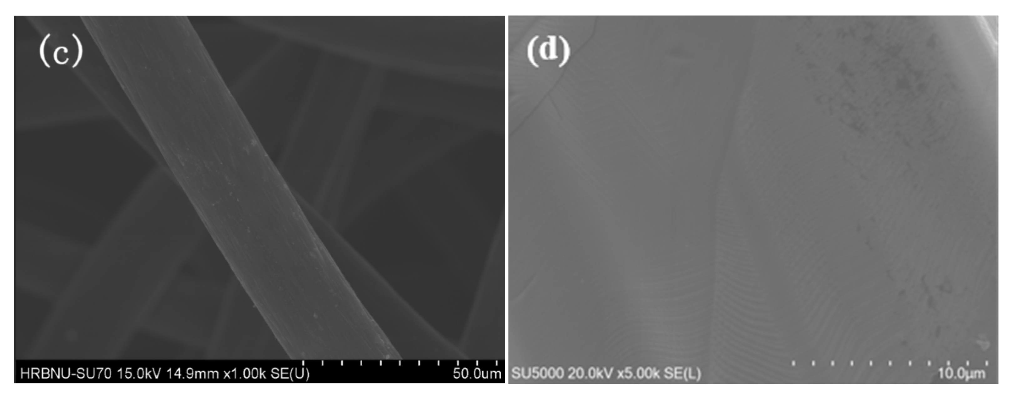
3.1.1. SEM: Scanning Electron Microscopy Analysis

SEM observation was used to study the loading conditions and micro-morphology characteristics of the CF-NiO-PANI electrode surface after polymerization of PANI, as shown in Figure 2.
Figure 2a,b are electron microscope images of the CF-NiO-PANI electrode under 1000 times and 5000 times scanning electron microscope, respectively; (c) and (d) are electron microscope images of blank CF electrode under 1000 times and 5000 times scanning electron microscope, and it can be seen that the surface of CF carbon fiber filament is smooth. From Figure 2a, it can be seen that the surface of the CF-NiO-PANI electrode carbon fiber filament is completely coated by polyaniline, and the polymerization effect is uniform and tight, which proves that the polymer is successfully loaded on CF-NiO in the experiment. It can be seen from Figure 2b that the polyaniline loading condition on the electrode surface is good, which forms a plate-like three-dimensional structure with appropriate gaps on the CF surface by NiO, which makes it easier for polyaniline to adhere to the electrode carbon fiber filament. The rod-like structure on the surface of carbon fiber filament is rod-like polyaniline prepared using the ice water bath method; the surface of carbon fiber filament is rough, which is more conducive to microorganism adhesion. In summary, the rod-like polyaniline is successfully loaded on the CF-NiO electrode in the experiment to form CF-NiO-PANI.

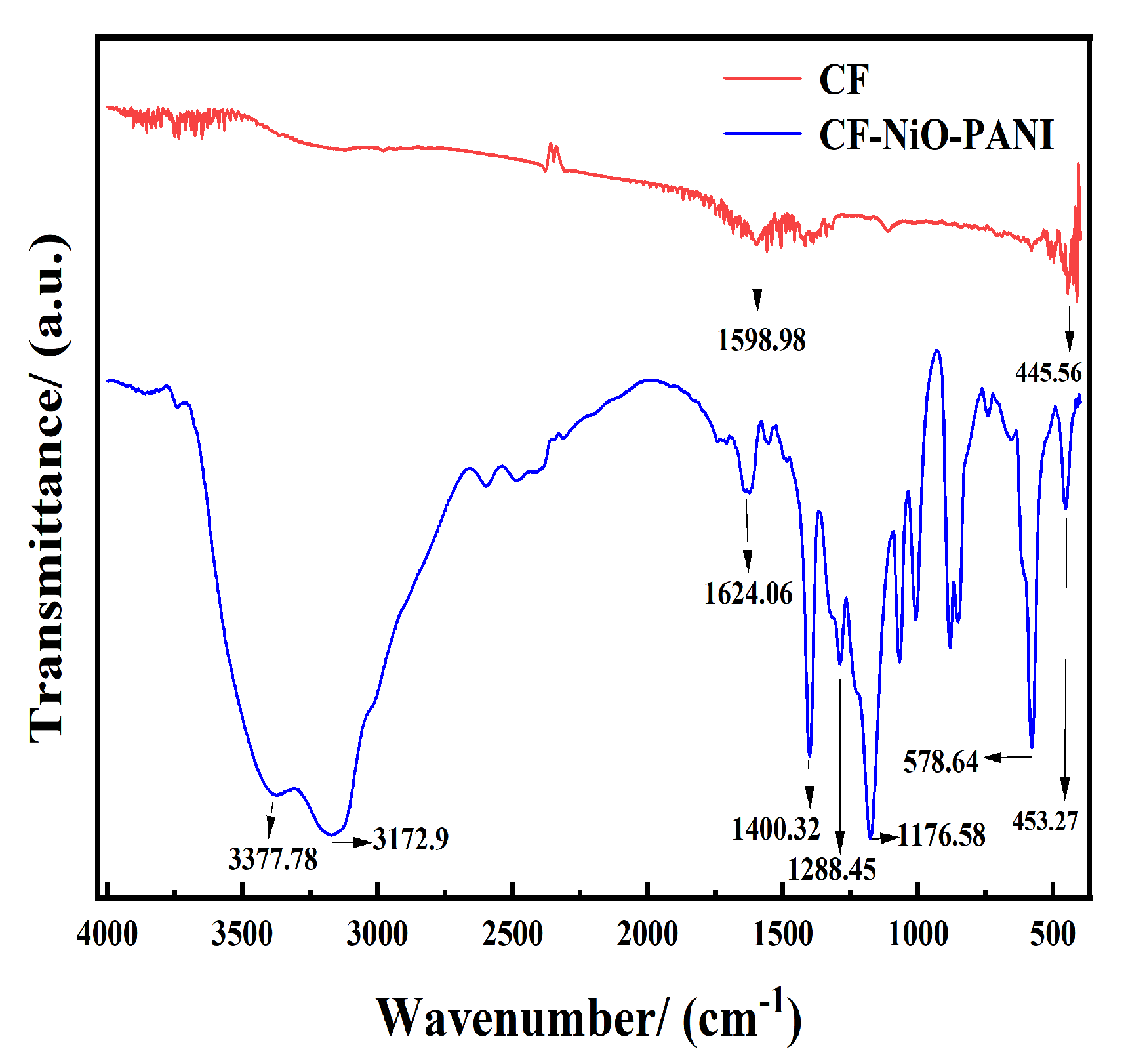
3.1.2. FTIR: Fourier Transform Infrared Spectroscopy

The functional groups and chemical bonds of the CF-NiO-PANI electrode after polymerization of PANI were studied using the FTIR test, as shown in Figure 3.
It can be seen from the figure that the CF-NiO-PANI electrode has its N-H stretching vibration peak at 3377.78 cm−1 and 3172.9 cm−1; a quinone ring C=C stretching vibration peak at 1624.06 cm−1; a benzene ring C=C stretching vibration peak at 1400.32 cm−1; and a secondary amine C-N stretching vibration peak at 1288.45 cm−1. The peak at 1178 cm−1 is the N=Q=N bond of the polyaniline molecular chain connected with the C=N bond of the quinone ring. The above peaks are characteristic peaks of polyaniline. Because NiO and PANI are co-supported on the electrode, the existence of NiO shifts the peak position. The peak at 453.27 cm−1 is the vibration peak of the NiO bond, and the peak at 578.64 cm−1 may be the coordination peak of NiO and PANI. The FTIR results show that NiO and PANI have been successfully supported on the CF electrode [42,43,44].

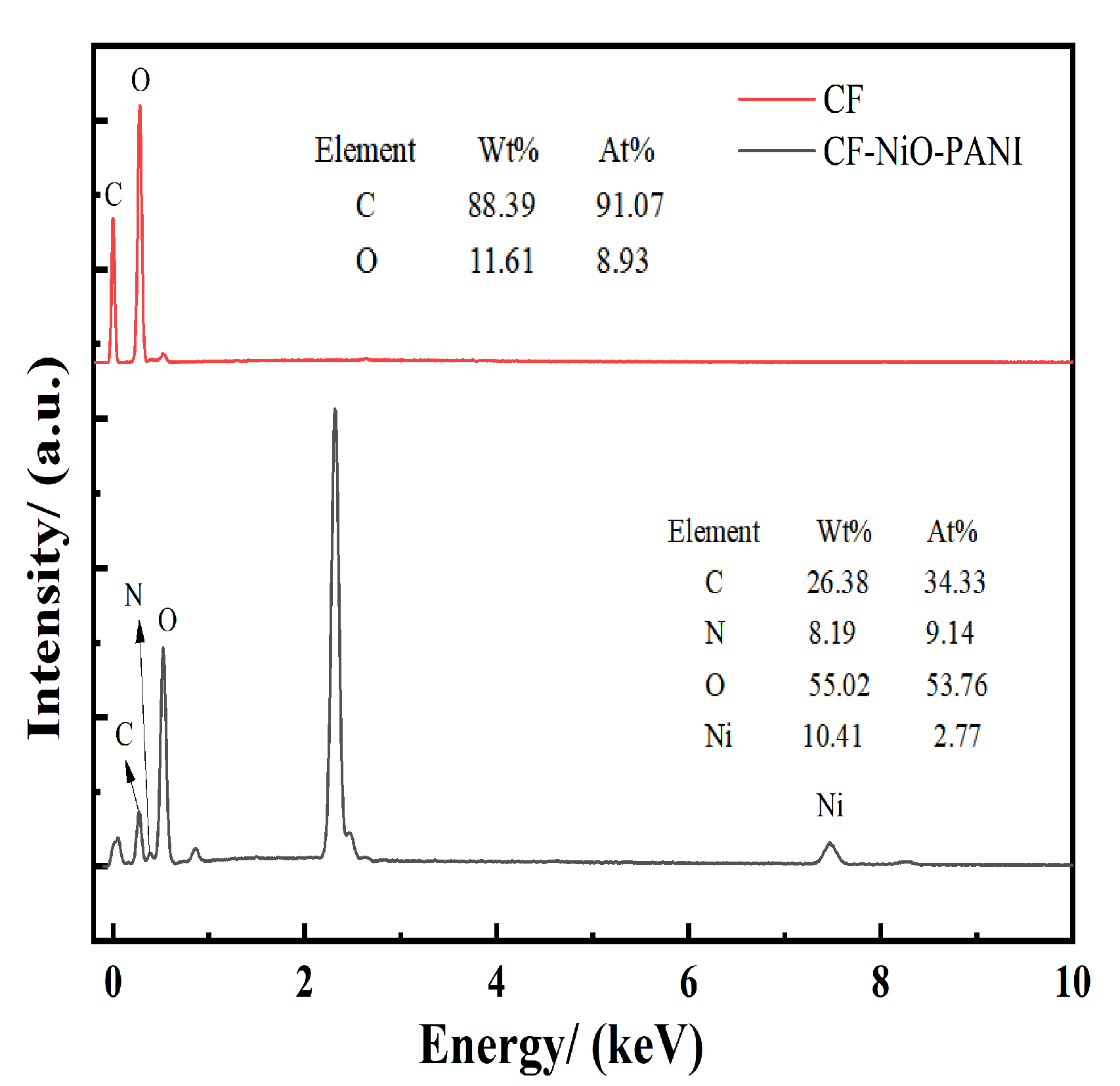
3.1.3. EDS: Energy Diffusion Spectrometer

The surface element types and contents of the CF-NiO-PANI electrode were analyzed by EDS, as shown in Figure 4.
As shown in Figure 4, the mass fractions of carbon and oxygen on the surface of the CF sample are 88.39% and 11.61%, respectively; the mass fractions of carbon, nitrogen, oxygen, and nickel on the surface of the CF-NiO-PANI sample are 26.38%, 8.19%, 55.02%, and 10.41%, respectively. Since CF-NiO-PANI was prepared on the CF-NiO electrode, the CF-NiO electrode did not contain the N element, which proved that the nitrogen element in the material came from the polyaniline supported on the electrode [45].

3.2. MFC Performance Test of the CF-NiO-PANI Anode

The CF-NiO-PANI electrode is used as the anode of the MFC cell, potato starch wastewater is used as the anode solution, the microbial fuel cell is started according to the above instructions, organic matter in wastewater is used to provide nutrients for microbial electricity-producing bacteria, and organic matter is decomposed to produce electrochemical efficiency. The performance of the battery anode has an important influence on electricity-producing efficiency, so the electrochemical efficiency of MFC at this time is tested by comparing the modified electrode with the original blank electrode.

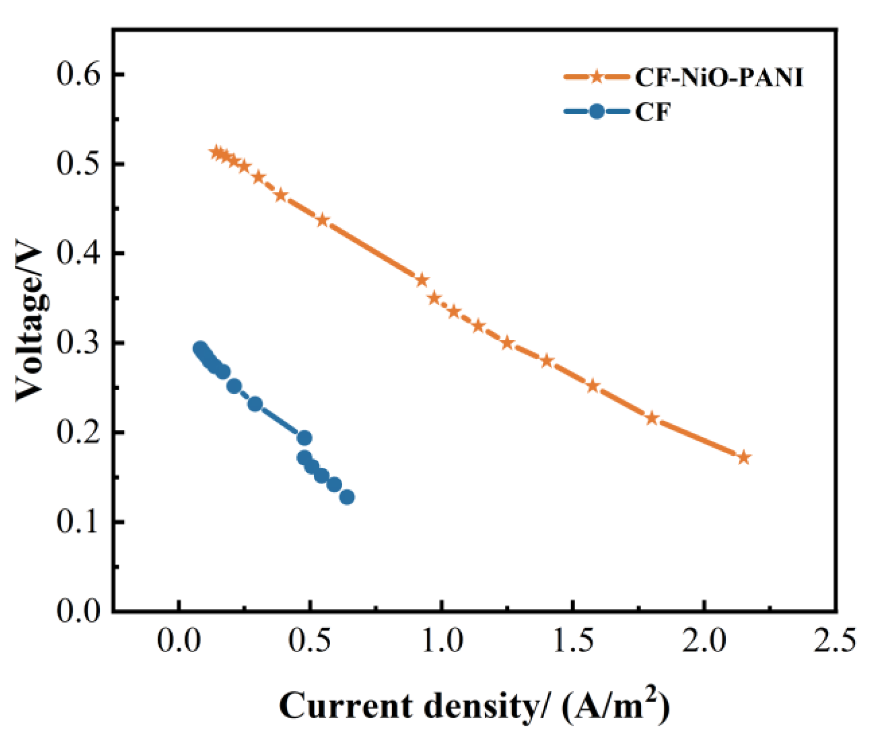
3.2.1. Polarization Curve

The polarization curves of MFC with a CF-NiO-PANI electrode and a blank CF electrode as an anode are shown in Figure 5.
As shown in Figure 5, the open circuit voltage of the CF-NiO-PANI electrode is 0.513 V, compared with 0.294 V of CF, and the polymer PANI electrode has the highest open circuit voltage, which is 0.219 V higher than CF. The curves show that with the increase of current density, the output voltage of the MFC polarization curve of the CF-NiO-PANI anode changes more slowly than CF. For example, when the current density value in the figure is 0.3–0.5 A/m2, the output voltage of the CF electrode decreases by 0.07 V, while the CF-NiO-PANI electrode decreases by 0.048 V. The polarization degree is the lowest among the two electrodes, indicating that the electrode loaded with PANI and NiO has better performance.

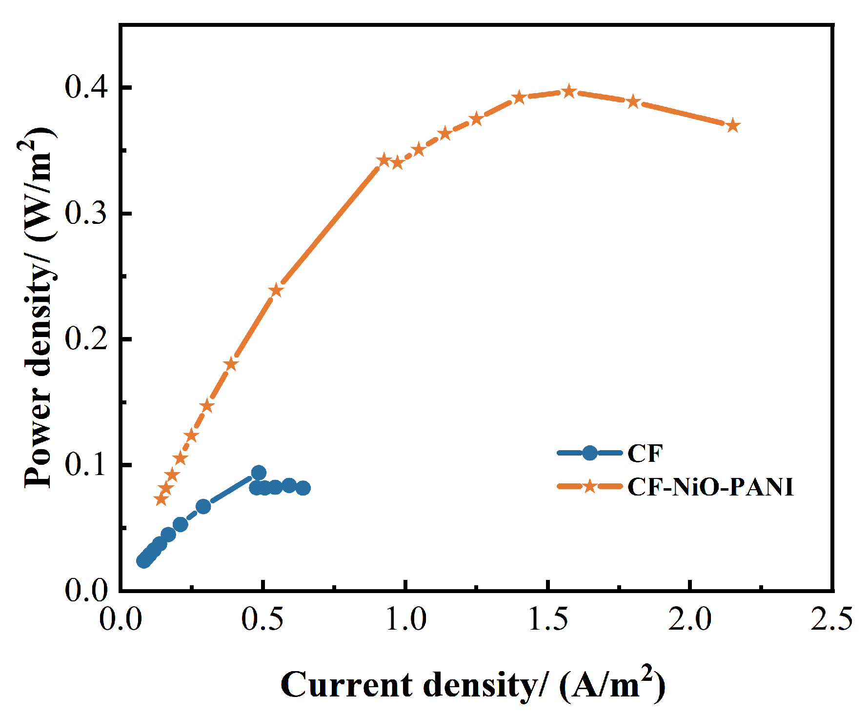
3.2.2. Power Density Curve

The power density curves of the MFC with a CF-NiO-PANI electrode and a blank CF electrode as an anode are shown in Figure 6.
As shown in Figure 6, the CF-NiO-PANI electrode can have a maximum output power of 0.4 W/m2 under the same other conditions of the MFC reactor, and the maximum power density of the CF-NiO-PANI electrode is 0.306 W/m2 higher than that of the CF electrode in MFC. Therefore, the introduction of PANI synthesized in an ice water bath can promote the charge transfer of the electrode, and MFC with CF-NiO-PANI as the anode has a stronger power generation ability.

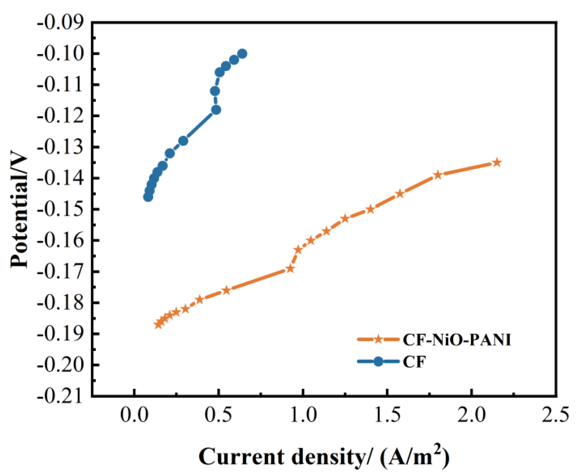
3.2.3. Anode Polarization Curve

The anodic polarization curves of MFC with a CF-NiO-PANI electrode and a blank CF electrode as an anode are shown in Figure 7.
It can clearly be seen in Figure 7 that the change trend of the CF-NiO-PANI electrode is gentler than that of the other electrodes under the same conditions. In the same interval, the CF anode is polarized by 0.024 V, while the CF-NiO-PANI electrode is only polarized by 0.011 V. The polarization degree is small, which is 0.013 V different from the CF electrode, indicating that after gradual modification, the polarization degree of the electrode decreases, and the bioelectrocatalytic activity increases. The NiO and PANI modified electrodes increased the specific surface area of the electrode, which made the electro-generating microorganisms in MFC adhere better and electron transfer easier, thus improving the electro-generation performance of MFC.

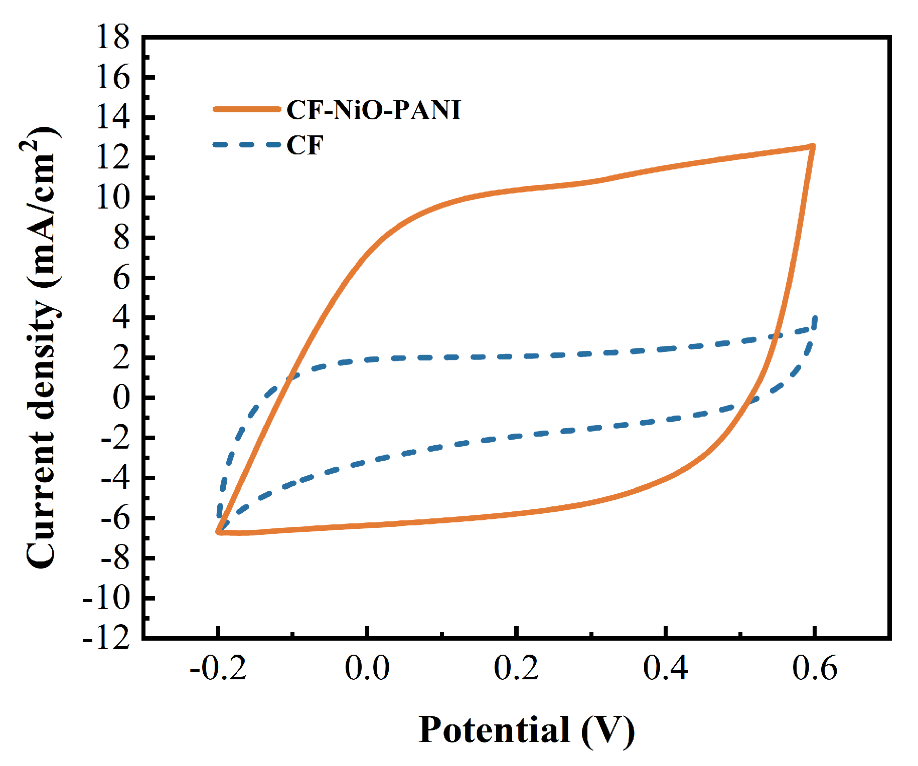
3.2.4. MFC Cyclic Voltammetry Test

Cyclic voltammetry curves in MFC with a CF-NiO-PANI electrode and a blank CF electrode as an anode, with a scan rate of 20 mV/s, are shown in Figure 8.
As shown in Figure 8, the area enclosed by the CF electrode cyclic voltammetry curve is the smallest and the area enclosed by the CF-NiO-PANI electrode curve is the largest among the cyclic voltammetry curve areas after MFC microbial acclimation, reflecting that the electrocatalytic activity of the CF electrode is obviously enhanced after NiO and PANI are modified and introduced on the CF electrode, and the CF-NiO-PANI electrode can form biofilm on the surface easier, which can increase the diversity of microorganisms and promote the growth of electricity-producing bacteria.

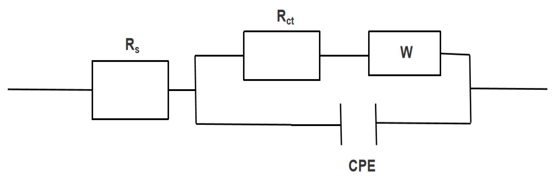
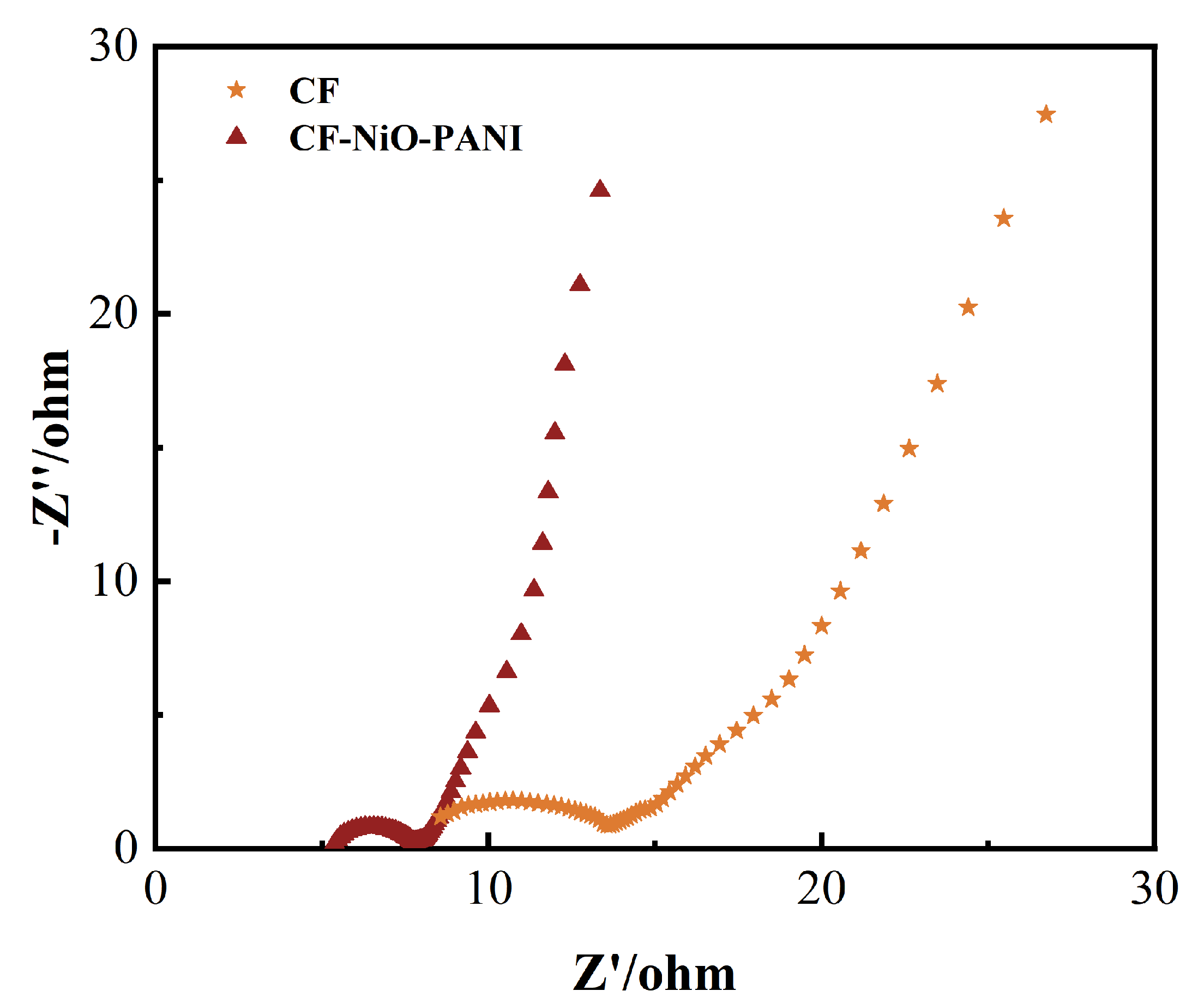
3.2.5. MFC AC Impedance Test

The equivalent impedance fitting circuit diagram of MFC with a CF-NiO-PANI electrode and a blank CF electrode as an anode is shown in Figure 9.
As can be seen in Figure 10 and Table 1, the EIS diagram after microbial acclimation in MFC consists of a semicircle as a high frequency region, a semicircle, and an X linear type, and the solution impedance RΩ and electron transfer impedance Rct can be calculated by fitting from the semicircle high frequency region: 1.57 Ω and Rct 4.48 Ω; RΩ and Rct of CF electrode are 7.23 Ω and 10.18 Ω, respectively. The impedance of PANI polymerized electrode solution and electron transfer impedance are lower than those of the CF electrode, which reflects that PANI polymerized in the outer layer of the electrode can reduce the impedance in the process of electron transfer. This is because PANI can strengthen the interaction between the electrode surface and biofilm, which is more conducive to electron transfer.

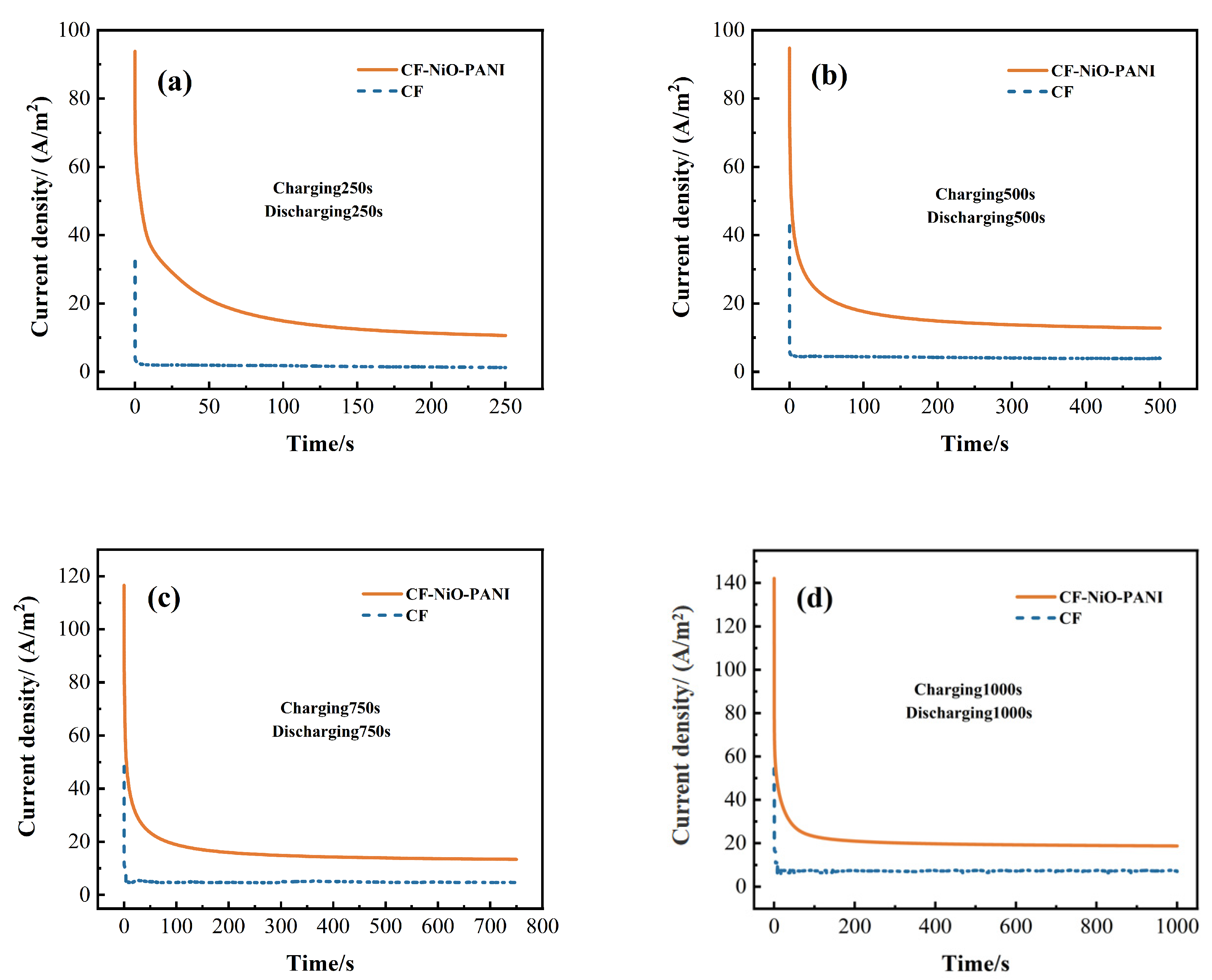
3.2.6. MFC Energy Storage Test

Discharge curves of an MFC anode with a CF-NiO-PANI electrode and a blank CF electrode under different charging times are shown in Figure 11a–d.
The MFC was tested under four different charging and discharging times: (a) charging for 250 s and discharging for 250 s with a discharge curve of (C250/D250); (b) charge 500 s and discharge 500 s with a discharge curve of (C500/D500); (c) charge 750 s and discharge 750 s with a discharge curve of (C750/D750); and (d) charge 1000 s and discharge 1000 s with a discharge curve of (C1000/D1000). It can be seen from the figure that the current density of the discharge curve decreases with the increase of time, where ih is the current density value at the beginning of discharge, is is the current density value at the stable time after discharge for a period of time, and Qs and Qt are the stored electric quantity and the total electric quantity generated during discharge, respectively.
It is shown in Figure 11 that the maximum current density of the CF-NiO-PANI electrode in the discharge curve of four groups of charge and discharge times is higher than that of the other two electrodes, reflecting that the electrode polymerized PANI in MFC has the most stored electricity under different charge and discharge conditions. The CF-NiO-PANI electrode has the largest stationary current density in the four groups of discharge curves, which proves that the CF-NiO-PANI electrode has a higher energy storage capacity than the blank CF electrode. The specific value is shown in the table. It can be seen that the longer the charging time, the higher the value. This is because the longer the charging time, the more the stored electricity of the electrode, and the ih increases accordingly, prolonging the required time for discharge.
As shown in Table 2, under C250/D250 conditions, the CF-NiO-PANI electrode exhibited Qs and Qt values of 1625.34 C/m2 and 4287.3 C/m2, respectively, representing increases of 1515.38 C/m2 and 3867.34 C/m2 compared to the CF electrode. Similarly, at C500/D500 conditions, the CF-NiO-PANI electrode achieved Qs and Qt values of 1757.85 C/m2 and 8157.85 C/m2, showing improvements of 1632.25 C/m2 and 6066 C/m2 over the CF electrode. Under C750/D750 conditions, the CF-NiO-PANI electrode demonstrated Qs and Qt values of 2205.9 C/m2 and 12,263.4 C/m2, with enhancements of 2028.01 C/m2 and 8607.76 C/m2, respectively, compared to the CF electrode. Notably, at C1000/D1000 conditions, the CF-NiO-PANI electrode reached Qs and Qt values of 2607.06 C/m2 and 20,886.67 C/m2, significantly outperforming the CF electrode by 2258.29 C/m2 and 13,582.9 C/m2. These results clearly indicate that the CF-NiO-PANI electrode exhibits substantially enhanced Qs and Qt values compared to the CF electrode.
These comprehensive data demonstrate that the incorporation of PANI and NiO effectively improves the electrode’s charge storage capacity. This enhancement can be attributed to two key factors: first, both NiO and PANI function as pseudocapacitive materials, endowing the electrode with intrinsic charge storage capability; second, these materials synergistically enhance the electrocatalytic activity of electrogenic bacteria, thereby boosting electricity generation performance. Additionally, the composite structure provides favorable sites for microbial metabolism, further contributing to the improved bioelectrochemical performance.

3.3. MFC (CF-NiO-PANI Anode) High-Throughput Sequencing

High-throughput sequencing technology is a technology to determine DNA molecular sequence, which is very important for microbial-related research. In this experiment, we determined the microbial sequence on the modified anode surface and studied the reasons for improving the electricity generation performance of the MFC anode. Figure 12 shows the Venn diagram of microbial species classification on CF-NiO-PANI and CF anode surfaces. CF-NiO-PANI is represented by A1, and CF is represented by A2. Figure 13 shows the histogram of microbial community structure distribution on the CF-NiO-PANI anode and the CF anode. Figure 14 and Figure 15 show 3D pie diagrams of microbial species abundance on the CF-NiO-PANI anode and the CF anode. Figure 16 shows a histogram of microbial species abundance on the CF-NiO-PANI anode and the CF anode.
(1)
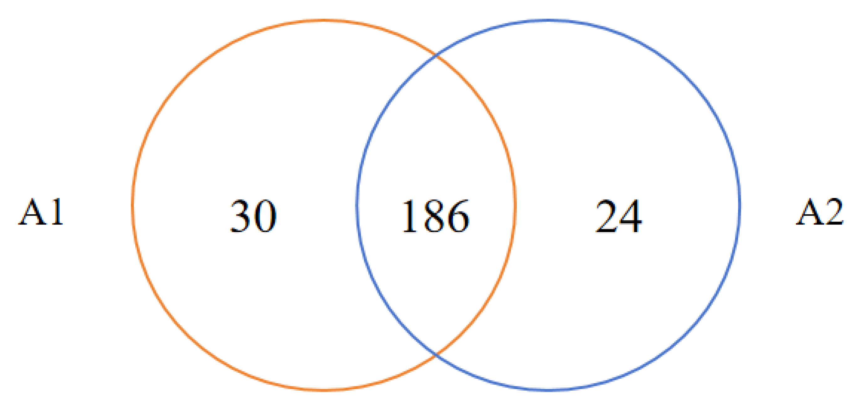
A Venn diagram of species classification of two anodes at the family level is shown in Figure 12.
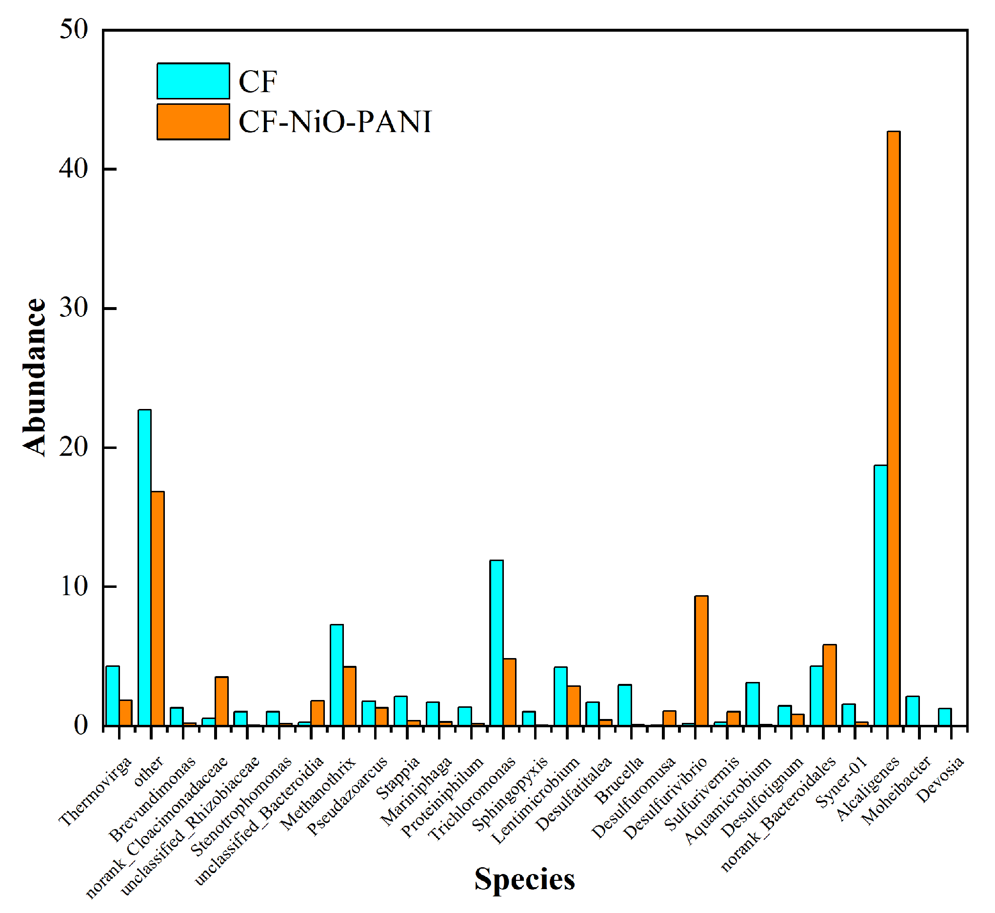
As shown in Figure 12, in the Venn diagram of species classification of two electrodes at genus level it can be intuitively seen that the total number of microbial species in A1 is higher than that in A2, the total number of OTUs in A1 is 216, while the total number of OTUs in A2 is 210, and the number of OTUs co-existing in A1 and A2 is 186. This result reflects that there are some similar microbial species in A1 and A2, which may be due to the domestication of microorganisms in the same environment when the MFC is started. However, there are also differences in the microbial species composition between A1 and A2. Among them, A1 contains 30 unique operational taxonomic units (OTUs), while A2 has 24 unique OTUs. This indicates that the modification of carbon felt (CF) by NiO-PANI material enhances the biocompatibility of the electrode, enabling A1 to host more unique species. At the same time, the increase in the proportion of electrogenic bacteria significantly improves the power density of the microbial fuel cell (MFC) equipped with CF-NiO-PANI electrodes (Figure 6). The differences in community structure may be closely related to the chemical properties, electrical conductivity, and biocompatibility of the electrode surface, thereby affecting the electron transfer efficiency and the overall performance of the system.
(2)
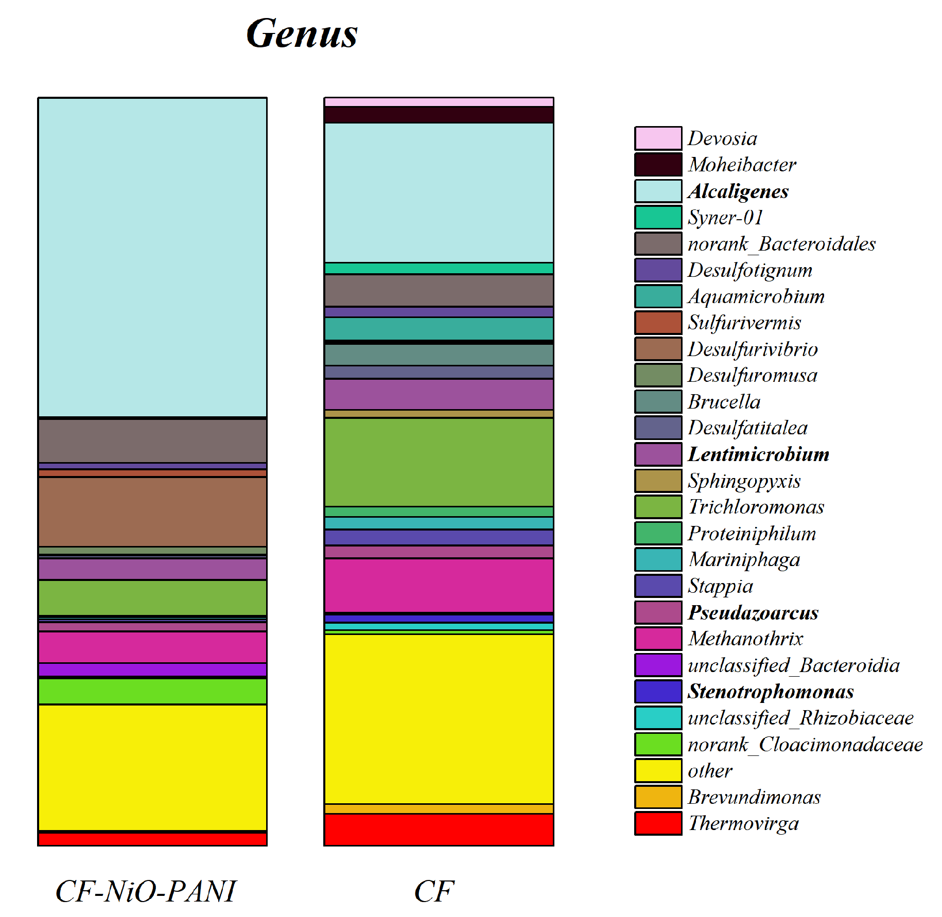
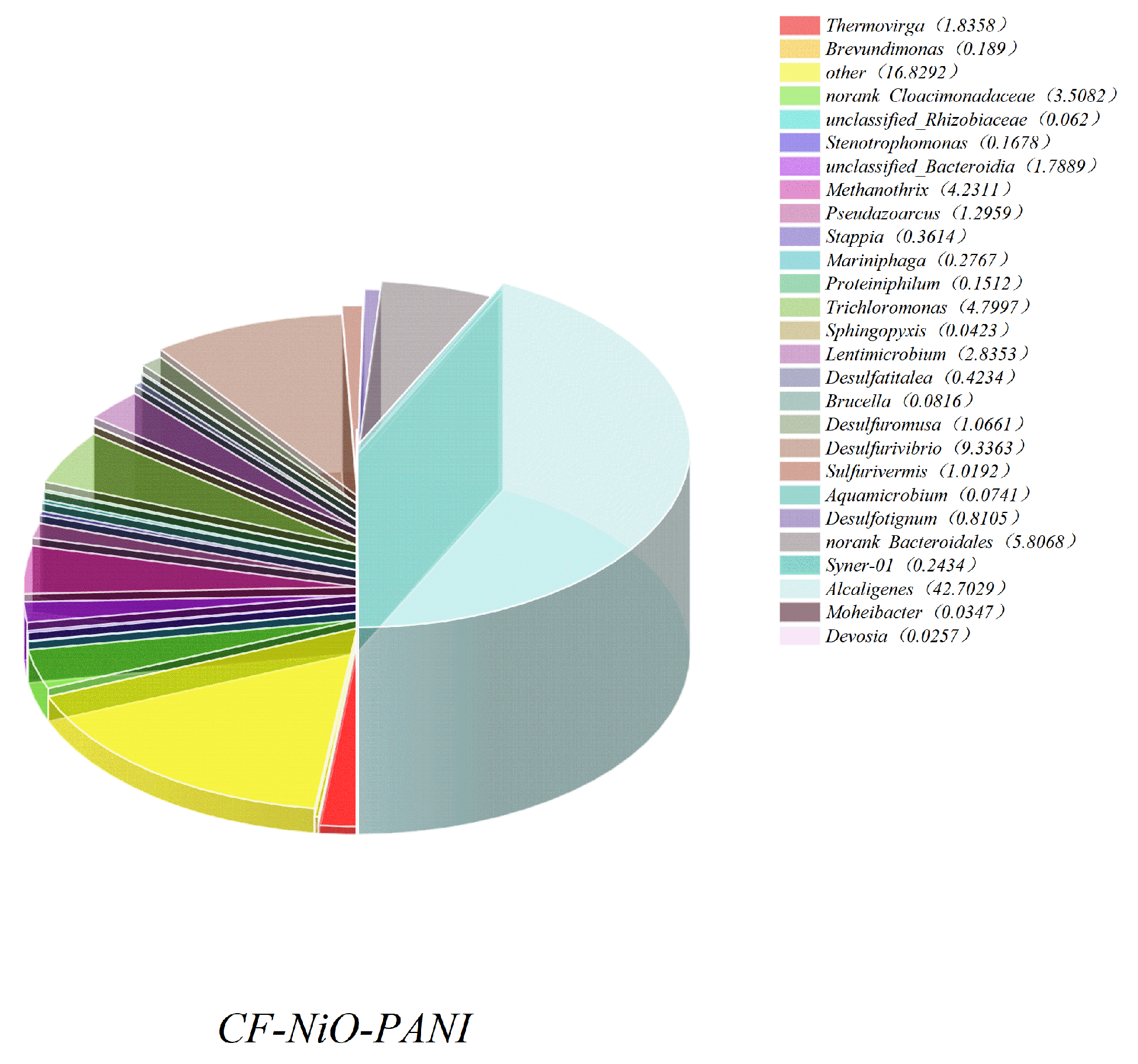
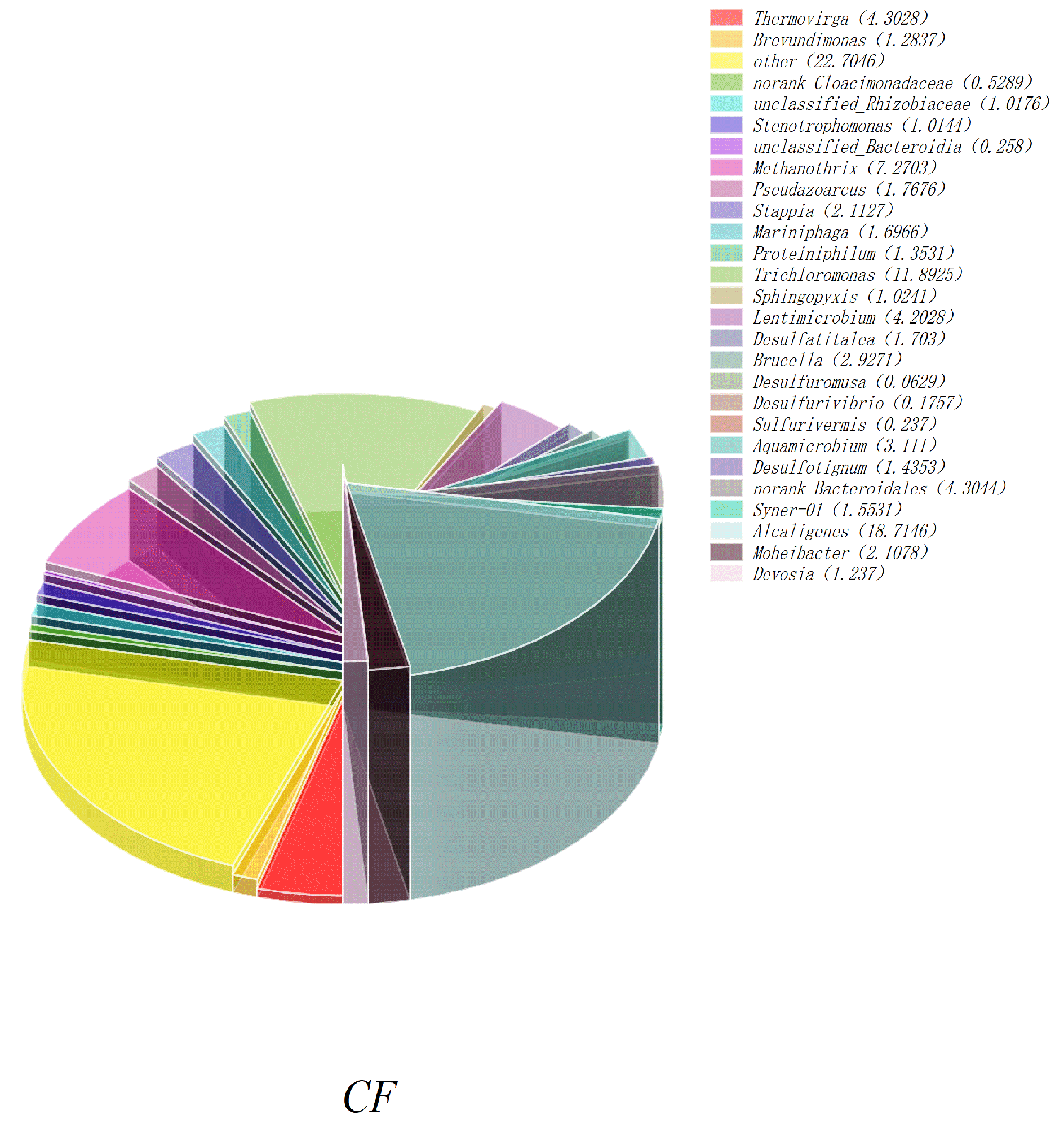
Figure 13 shows the histogram of microbial community structure distribution of CF-NiO-PANI and CF anodes at the genus level. It can be visually seen that the microbial community of the CF-NiO-PANI anode is rich in species, among which, the electrogenic microorganisms are Stenotrophomonas, Pseudoarcus, Alcaligenes, and Lentimicrobe. Alcaligenes occupy a large proportion of the CF-NiO-PANI anode and are the main electrogenic bacteria of the CF-NiO-PANI electrode. Alcaligenes are resistant to harsh environments and have certain tolerance to high salt, extreme pH, or heavy metal pollution environments, which makes them suitable for industrial wastewater treatment. They can also improve the overall electricity generation performance through symbiosis in mixed bacteria, showing good synergy.
(3)
Figure 14 and Figure 15 show 3D pie charts of microbial species abundance on CF-NiO-PANI and CF anodes at the generic level.
In Figure 14 and Figure 15, we can see the proportion of microorganisms on the electrode surface of each microbial strain, among which Stenotrophomonas, the main electrogenic bacteria of the CF-NiO-PANI anode loaded microorganisms, (0.17%), Pseudazoarcus (1.30%), Alcaligenes (42.70%), and Lentimicrobium CF-NiO-PANI had a significant advantage in the number of electrogenic bacteria compared with the CF anode (25.68%), and the total electrogenic bacteria of CF-NiO-PANI was 21.33% higher than that of the CF anode, which was due to PANI being easier for microorganisms to attach and grow. Therefore, when the CF-NiO-PANI anode was used in MFC, most of the organic matter was decomposed by electrogenic bacteria to produce electrons and protons, which converted the metabolic ability of microorganisms to organic matter into electrical energy. The proportion of organic matter consumed by non-electrogenic bacteria decreased, and the electrogenic performance was enhanced, which was consistent with the electrode preparation and related MFC test results.
Figure 16 shows the histogram of species abundance of CF-NiO-PANI and CF anodes, in which the main microbial flora of each anode can be seen. The main microbial flora of the two kinds of anode is relatively concentrated, and the ones with higher abundance in CF-NiO-PANI are electricity-producing bacteria, which confirms the above conclusion.

4. Conclusions

In this study, the preparation of the CF-NiO-PANI electrode and its electricity generation performance in a microbial fuel cell were systematically studied. The CF-NiO-PANI electrode prepared in this study improves biocompatibility through modification, promotes microbial attachment and biofilm formation, and enhances electron transfer, thereby improving the power density and energy storage performance of the MFC.
Through energy storage performance tests, it is shown that in standard charge–discharge tests (C1000/D1000), the charge release of CF-NiO-PANI anode is 20,886.67 C/m2, which is higher than that of CF anode (7303.77 C/m2), which had an increase of 186%. High-throughput sequencing analysis showed that the microbial community on the surface of the CF-NiO-PANI electrode had rich biodiversity, among which the proportion of electricity-producing bacteria was as high as 47.01%. Therefore, this new anode material enabled microbial fuel cells to not only realize the dual functions of power generation and energy storage simultaneously, but also to provide a continuous and stable power supply for low-power consumption devices. The potato starch wastewater was also utilized reasonably to realize green sustainable development.

Author Contributions

Conceptualization, Y.H.; software, J.W.; formal analysis, L.J.; investigation, W.L.; data curation, Y.H.; methodology and writing—original draft preparation, J.L.; writing—review and editing, Y.W.; supervision, T.Y.; resources, validation, Z.W.; project administration, and funding acquisition, J.Z. All authors have read and agreed to the published version of the manuscript.

Funding

This research was funded by the 2023 Heilongjiang Natural Science Foundation Joint Guidance Project (LH2023E029).

Institutional Review Board Statement

Not applicable.

Informed Consent Statement

Not applicable.

Data Availability Statement

The original contributions presented in this study are included in the article. Further inquiries can be directed to the corresponding author.

Conflicts of Interest

Author Jingyuan Wang is employed by China Municipal Engineering Zhongnan Design & Research Institute Co., Ltd., while Jiuming Lei works at the Ecological Environment Monitoring Station of Lincang Ecology and Environment Bureau. All other authors declare no potential conflicts of interest, confirming the research was conducted without any commercial or financial relationships that could be interpreted as influencing the study.

References

  1. Jong, D.H. Impact of the Potato on Society. Am. J. Potato Res. 2016, 93, 415–429. [Google Scholar] [CrossRef]
  2. Ovchinnikova, A.; Krylova, E.; Gavrilenko, T.; Smekalova, T.; Zhuk, M.; Knapp, S.; Spooner, D.M. Taxonomy of cultivated potatoes (Solanum section Petota: Solanaceae). Bot. J. Linn. Soc. 2011, 165, 107–155. [Google Scholar] [CrossRef]
  3. Camire, M.E.; Kubow, S.; Donnelly, D.J. Potatoes and human health. Crit. Rev. Food Sci. Nutr. 2009, 49, 823–840. [Google Scholar] [CrossRef]
  4. Li, Q.; Zhang, D.; Zhang, J.; Zhou, Z.; Pan, Y.; Yang, Z.; Zhu, J.; Liu, Y.; Zhang, L. Crop rotations increased soil ecosystem multifunctionality by improving keystone taxa and soil properties in potatoes. Front. Microbiol. 2023, 14, 1034761. [Google Scholar] [CrossRef]
  5. Wierzbowska, J.; Rychcik, B.; Światły, A. The effect of different production systems on the content of micronutrients and trace elements in potato tubers. Acta Agric. Scand. Sect. B—Soil Plant Sci. 2018, 68, 701–708. [Google Scholar] [CrossRef]
  6. Subramanian, N.K.; White, P.J.; Broadley, M.R.; Ramsay, G. The three-dimensional distribution of minerals in potato tubers. Ann. Bot. 2011, 107, 681–691. [Google Scholar] [CrossRef]
  7. Xu, J.; Li, Y.; Kaur, L.; Singh, J.; Zeng, F. Functional food based on Potato. Foods 2023, 12, 2145. [Google Scholar] [CrossRef]
  8. Pedreschi, F.; Moyano, P.; Santis, N.; Pedreschi, R. Physical properties of pre-treated potato chips. J. Food Eng. 2007, 79, 1474–1482. [Google Scholar] [CrossRef]
  9. Chen, Z.; Zhang, T.; Liu, Q.; Liu, W.; Zhao, R.; Hu, H. Effects of additives (NaCl, citric acid, and ethanol) on the cooking quality and sensory quality of vermicelli produced from freeze–thaw-dehydrated whole potato powder. Int. J. Food Sci. Technol. 2024, 59, 9459–9468. [Google Scholar] [CrossRef]
  10. Zhang, H.; Fen, X.U.; Yu, W.U.; Hu, H.H.; Dai, X.F. Progress of potato staple food research and industry development in China. J. Integr. Agric. 2017, 16, 2924–2932. [Google Scholar] [CrossRef]
  11. Wang, X.; Wang, J.; Liu, H.; Zhao, L.; Wang, Y.; Wu, X.; Liao, X. Improving the production efficiency of sweet potato starch using a newly designed sedimentation tank during starch sedimentation process. J. Food Process. Preserv. 2020, 44, e14811. [Google Scholar] [CrossRef]
  12. Durruty, I.; Bonanni, P.S.; González, J.F.; Busalmen, J.P. Evaluation of potato-processing wastewater treatment in a microbial fuel cell. Bioresour. Technol. 2012, 105, 81–87. [Google Scholar] [CrossRef] [PubMed]
  13. Shi, Y.; Liu, X.; Jin, M.; Chen, H.; Yi, F.; Wang, L.; Qiao, N.; Yu, D. Incorporating corn oil refining wastewater improves lipid accumulation and self-settling property of Trichosporon fermentans in corn starch wastewater. Sep. Purif. Technol. 2021, 275, 119250. [Google Scholar] [CrossRef]
  14. Li, M.; Zhu, X.; Yang, H.; Xie, X.; Zhu, Y.; Xu, G.; Hu, X.; Jin, Z.; Hu, Y.; Hai, Z.; et al. Treatment of potato starch wastewater by dual natural flocculants of chitosan and poly-glutamic acid. J. Clean. Prod. 2020, 264, 121641. [Google Scholar] [CrossRef]
  15. Moqsud, M.A.; Omine, K.; Yasufuku, N.; Hyodo, M.; Nakata, Y. Microbial fuel cell (MFC) for bioelectricity generation from organic wastes. Waste Manag. 2013, 33, 2465–2469. [Google Scholar] [CrossRef]
  16. Oliveira, V.B.; Simões, M.; Melo, L.F.; Pinto, A.M.F.R. Overview on the developments of microbial fuel cells. Biochem. Eng. J. 2013, 73, 53–64. [Google Scholar] [CrossRef]
  17. Mohan, S.V.; Raghavulu, S.V.; Peri, D.; Sarma, P.N. Integrated function of microbial fuel cell (MFC) as bio-electrochemical treatment system associated with bioelectricity generation under higher substrate load. Biosens. Bioelectron. 2009, 24, 2021–2027. [Google Scholar] [CrossRef]
  18. Aiyer, K.S. How does electron transfer occur in microbial fuel cells? World J. Microbiol. Biotechnol. 2020, 36, 19. [Google Scholar] [CrossRef]
  19. Ieropoulos, I.A.; Greenman, J.; Melhuish, C.; Hart, J. Comparative study of three types of microbial fuel cell. Enzym. Microb. Technol. 2005, 37, 238–245. [Google Scholar] [CrossRef]
  20. Cecconet, D.; Molognoni, D.; Callegari, A.; Capodaglio, A.G. Agro-food industry wastewater treatment with microbial fuel cells: Energetic recovery issues. Int. J. Hydrogen Energy 2018, 43, 500–511. [Google Scholar] [CrossRef]
  21. Ghasemi, M.; Daud, W.R.W.; Hassan, S.H.A.; Oh, S.E.; Ismail, M.; Rahimnejad, M.; Jahim, J.M. Nano-structured carbon as electrode material in microbial fuel cells: A comprehensive review. J. Alloys Compd. 2013, 580, 245–255. [Google Scholar] [CrossRef]
  22. Zhou, M.; Chi, M.; Luo, J.; He, H.; Jin, T. An overview of electrode materials in microbial fuel cells. J. Power Sources 2011, 196, 4427–4435. [Google Scholar] [CrossRef]
  23. Zhu, K.; Wang, S.; Liu, H.; Liu, S.; Zhang, J.; Yuan, J.; Fu, W.; Dang, W.; Xu, Y.; Yang, X.; et al. Heteroatom-doped porous carbon nanoparticle-decorated carbon cloth (HPCN/CC) as efficient anode electrode for microbial fuel cells (MFCs). J. Clean. Prod. 2022, 336, 130374. [Google Scholar] [CrossRef]
  24. Santoro, C.; Li, B.; Cristiani, P.; Squadrito, G. Power generation of microbial fuel cells (MFCs) with low cathodic platinum loading. Int. J. Hydrogen Energy 2013, 38, 692–700. [Google Scholar] [CrossRef]
  25. Wang, P.; Li, H.; Du, Z. Polyaniline synthesis by cyclic voltammetry for anodic modification in microbial fuel cells. Int. J. Electrochem. Sci. 2014, 9, 2038–2046. [Google Scholar] [CrossRef]
  26. Cui, H.F.; Du, L.; Guo, P.B.; Zhu, B.; Luong, J.H. Controlled modification of carbon nanotubes and polyaniline on macroporous graphite felt for high-performance microbial fuel cell anode. J. Power Sources 2015, 283, 46–53. [Google Scholar] [CrossRef]
  27. Wang, Y.; Ma, S.; Hou, L.; Zuo, J.; Kong, X.; Song, Y.; Wang, Z.; Tian, Y.; Dong, J. Enhanced electricity generation and energy storage in a microbial fuel cell with a bimetallic-modified capacitive anode. Desalination 2025, 593, 118247. [Google Scholar] [CrossRef]
  28. Yin, T.; Lin, Z.; Su, L.; Yuan, C.; Fu, D. Preparation of vertically oriented TiO2 nanosheets modified carbon paper electrode and its enhancement to the performance of MFCs. ACS Appl. Mater. Interfaces 2015, 7, 400–408. [Google Scholar] [CrossRef]
  29. Gnana kumar, G.; Kirubaharan, C.J.; Udhayakumar, S.; Karthikeyan, C.; Nahm, K.S. Conductive polymer/graphene supported platinum nanoparticles as anode catalysts for the extended power generation of microbial fuel cells. Ind. Eng. Chem. Res. 2014, 53, 16883–16893. [Google Scholar] [CrossRef]
  30. Ma, X.; Feng, C.; Zhou, W.; Yu, H. Municipal sludge-derived carbon anode with nitrogen-and oxygen-containing functional groups for high-performance microbial fuel cells. J. Power Sources 2016, 307, 105–111. [Google Scholar] [CrossRef]
  31. Wang, Y.; Wang, Z.; Hu, G. Bifunctional polypyrrole/ferroferric oxide as anode material for enhanced electricity generation and energy storage in microbial fuel cell. Renew. Energy 2023, 219, 119432. [Google Scholar] [CrossRef]
  32. Wu, Y.; Zhang, X.; Li, S.; Lv, X.; Cheng, Y.; Wang, X. Microbial biofuel cell operating effectively through carbon nanotube blended with gold–titania nanocomposites modified electrode. Electrochim. Acta 2013, 109, 328–332. [Google Scholar] [CrossRef]
  33. Li, C.; Zhang, L.; Ding, L.; Ren, H.; Cui, H. Effect of conductive polymers coated anode on the performance of microbial fuel cells (MFCs) and its biodiversity analysis. Biosens. Bioelectron. 2011, 26, 4169–4176. [Google Scholar] [CrossRef] [PubMed]
  34. Hanafi, M.F.; Sapawe, N. A review on the current techniques and technologies of organic pollutants removal from water/wastewater. Mater. Today: Proc. 2020, 31, A158–A165. [Google Scholar] [CrossRef]
  35. He, Z.; Minteer, S.D.; Angenent, L.T. Electricity generation from artificial wastewater using an upflow microbial fuel cell. Environ. Sci. Technol. 2005, 39, 5262–5267. [Google Scholar] [CrossRef]
  36. Liu, H.; Ramnarayanan, R.; Logan, B.E. Production of electricity during wastewater treatment using a single chamber microbial fuel cell. Environ. Sci. Technol. 2004, 38, 2281–2285. [Google Scholar] [CrossRef]
  37. Makhtar, M.M.Z.; Don, M.M.; Tajarudin, H.A. Microbial fuel cell (MFC) development from anaerobic digestion system. In Anaerobic Digestion Processes: Applications and Effluent Treatment; Springer: Singapore, 2018; pp. 9–31. [Google Scholar]
  38. Hindatu, Y.; Annuar, M.S.M.; Gumel, A.M. Mini-review: Anode modification for improved performance of microbial fuel cell. Renew. Sustain. Energy Rev. 2017, 73, 236–248. [Google Scholar] [CrossRef]
  39. Arun, J.; SundarRajan, P.S.; Pavithra, K.G.; Priyadharsini, P.; Shyam, S.; Goutham, R.; Le, Q.; Pugazhendhi, A. New insights into microbial electrolysis cells (MEC) and microbial fuel cells (MFC) for simultaneous wastewater treatment and green fuel (hydrogen) generation. Fuel 2024, 355, 129530. [Google Scholar] [CrossRef]
  40. Hamedani, E.A.; Abasalt, A.; Talebi, S. Application of microbial fuel cells in wastewater treatment and green energy production: A comprehensive review of technology fundamentals and challenges. Fuel 2024, 370, 131855. [Google Scholar] [CrossRef]
  41. Wu, Q.; Jiao, S.; Ma, M.; Peng, S. Microbial fuel cell system: A promising technology for pollutant removal and environmental remediation. Environ. Sci. Pollut. Res. 2020, 27, 6749–6764. [Google Scholar] [CrossRef]
  42. Wei, G.; Chun, X.; Sheng, W.; Jiang, S. Capacitive performance of polyaniline prepared by soft template method. Procedia Eng. 2012, 27, 1378–1385. [Google Scholar] [CrossRef]
  43. Mahanta, D.; Manna, U.; Madras, G.; Patil, S. Multilayer self-assembly of TiO2 nanoparticles and polyaniline-grafted-chitosan copolymer (CPANI) for photocatalysis. ACS Appl. Mater. Interfaces 2011, 3, 84–92. [Google Scholar] [CrossRef] [PubMed]
  44. Tiwari, A.; Gong, S. Electrochemical Synthesis of Chitosan-co-polyaniline/WO3⋅nH2O Composite Electrode for Amperometric Detection of NO2 Gas. Electroanal. Int. J. Devoted Fundam. Pract. Asp. Electroanal. 2008, 20, 1775–1781. [Google Scholar] [CrossRef]
  45. Wang, Y.; Wang, Z.; Zhang, D.; Kong, X.; Song, Y.; Ma, S.; Duan, Y.; Vyshnikin, A.; Palchykov, V. Carbon Felt/Nickel Oxide/Polyaniline Nanocomposite as a Bifunctional Anode for Simultaneous Power Generation and Energy Storage in a Dual-Chamber MFC. Coatings 2025, 15, 356. [Google Scholar] [CrossRef]
Figure 1. Chemical reaction diagram of CF-NiO-PANI electrode preparation.
Coatings 15 00776 g001
Figure 2. (a,b) SEM images of the CF-NiO-PANI electrode magnified 1000 and 5000 times; (c,d) SEM images of the CF electrode magnified 1000 and 5000 times.
Coatings 15 00776 g002aCoatings 15 00776 g002b
Figure 3. The FTIR of CF and CF-NiO-PANI electrodes.
Coatings 15 00776 g003
Figure 4. EDS spectrum of CF and CF-NiO-PANI electrode.
Coatings 15 00776 g004
Figure 5. Polarization curve test of CF-NiO-PANI and CF electrodes as the MFC anode.
Coatings 15 00776 g005
Figure 6. Power density curve test of CF-NiO-PANI and CF electrodes as the anode of MFC.
Coatings 15 00776 g006
Figure 7. Anodic polarization curve of CF-NiO-PANI and CF electrodes as MFC anodes.
Coatings 15 00776 g007
Figure 8. CV curves of CF-NiO-PANI and CF electrodes as an MFC anode.
Coatings 15 00776 g008
Figure 9. Equivalent fitting circuit diagram.
Coatings 15 00776 g009
Figure 10. EIS figures of CF-NiO-PANI and CF electrodes as MFC positive.
Coatings 15 00776 g010
Figure 11. Chronoamperometric curves polarized for the CF-NiO-PANI anode and the CF anode at different discharge times under closed-circuit conditions: (a) 250 s, (b) 500 s, (c) 750 s, and (d) 1000.
Coatings 15 00776 g011
Figure 12. Venn diagram of microbial species classification on CF-NiO-PANI and CF anode surfaces.
Coatings 15 00776 g012
Figure 13. Histogram of microbial community structure distribution of CF-NiO-PANI and CF electrodes.
Coatings 15 00776 g013
Figure 14. A 3D pie chart of microbial species abundance on the CF-NiO-PANI anode load.
Coatings 15 00776 g014
Figure 15. A 3D pie chart of microbial species abundance on the CF anode load.
Coatings 15 00776 g015
Figure 16. CF-NiO-PANI anode and CF anode species abundance histogram.
Coatings 15 00776 g016
Table 1. AC impedance values of MFC with different electrodes.
ElectrodeCFCF-NiO-PANI
RΩ (Ω)7.231.57
Rct (Ω)10.184.48
Table 2. Anode chrono-electric current test results after different charge and discharge times with CF-NiO-PANI and CF as MFC anodes.
ElectrodeCurrent and CapacityC250/D250C500/D500C750/D750C1000/D1000
CF ih (A/m2)37.3742.7648.3754.37
is (A/m2)1.283.934.736.95
Qs (C/m2)109.96125.60177.89348.77
Qt (C/m2)419.962091.853655.647303.77
CF-NiO-PANIih (A/m2)93.8094.76116.52142.13
is (A/m2)10.6412.8013.4118.78
Qs (C/m2)1625.341757.852205.902607.06
Qt (C/m2)4287.308157.8512,263.4020,886.67
Disclaimer/Publisher’s Note: The statements, opinions and data contained in all publications are solely those of the individual author(s) and contributor(s) and not of MDPI and/or the editor(s). MDPI and/or the editor(s) disclaim responsibility for any injury to people or property resulting from any ideas, methods, instructions or products referred to in the content.

