Abstract
The precision casting of nickel-based single-crystal superalloys imposes stringent requirements on the high-temperature stability and chemical inertness of ceramic shell face coats. To address the issue of traditional EC95 shells (95% Al2O3–5% SiO2) being prone to react with the alloy melt at elevated temperatures, thereby inducing casting defects, this study proposes a lanthanide oxide-based ceramic face coat material. Three distinct powders—LaAlO3 (LA), LaAlO3/La2Si2O7 (LAS), and LaAl11O18/La2Si2O7/Al2O3 (LA11S)—are successfully prepared through solid-phase sintering of the La2O3-Al2O3-SiO2 ternary system. Their slurry properties, shell sintering processes, and high-temperature performance are systematically investigated. The results demonstrate that optimal slurry coating effectiveness is achieved when LA powder is processed with a liquid-to-powder ratio of 3:1 and a particle size of 300 mesh. While LA shells show no cracking at 1300 °C, their face coats fail above 1400 °C due to the formation of a La2Si2O7 phase. In contrast, LAS and LA11S shells suppress cracking through the La2Si2O7 and LaAl11O18 phases, respectively, exhibiting exceptionally high-temperature stability at 1400 °C and 1500 °C. All three shells meet the high-temperature strength requirements for CMSX-4 single-crystal alloy casting. Interfacial reaction analysis and Gibbs free energy calculations reveal that Al2O3-forming reactions occur between the novel shells and alloy melt, accompanied by minor dissolution erosion without other chemical side reactions. This work provides a high-performance face coat material solution for investment casting of nickel-based superalloys.
1. Introduction
Nickel-based high-temperature alloys are widely used in critical areas such as aero-engine turbine blades and gas turbine hot-end components due to their excellent creep resistance, oxidation resistance and high-temperature strength [1,2]. During the casting of single-crystal alloys, traditional alumina-based ceramic shells (e.g., EC95) face two serious challenges. On the one hand, SiO2, as the main composition, reacts with the reactive elements (Al, Hf, etc.) at the interface in the alloys to generate impurities (e.g., Al2O3, HfO2), resulting in freckling defects on the surface of the castings [3,4,5]. On the other hand, the prepared shells are prone to deformation during sintering above 1500 °C, which makes it difficult to ensure the dimensional accuracy of the castings. Therefore, new surface material compositions need to be developed to form ceramic shells with excellent properties.
In recent years, rare earth oxide Y2O3 has been explored for high-temperature alloy casting due to its thermodynamic stability. However, its prohibitive cost significantly limits industrial-scale applications. In contrast, lanthanum oxide (La2O3), characterized by abundant domestic reserves, cost-effectiveness, high melting point, and elevated density, demonstrates superior feasibility for industrial implementation. At elevated temperatures, La2O3 reacts with Al2O3 and SiO2 to form thermally stable compounds, including LaAlO3, LaAl11O18, and La2Si2O7. Among these derivatives, lanthanum aluminate (LaAlO3) exhibits a Calcitonite structure, endowing it with exceptional thermal and chemical stability. As a novel rare earth particulate material, it finds extensive applications in solid oxide fuel cells, advanced ceramics, and substrate materials [6,7,8,9]. Two primary forms exist: stoichiometric La2O3-Al2O3 (1:1 molar ratio) sintering yields LaAlO3, while a 1:11 molar ratio produces LaAl11O18. LaAlO3 is used as a new type of high-temperature corrosion-resistant material in slag line bricks, which is superior to MgO-C bricks in resisting the erosion of steel slag [6]. Its excellent lattice matching with high-temperature superconductors further enables widespread use as a substrate material. Commercial production of LaAlO3 single crystals, particularly for high-temperature superconducting thin film substrates, has shown substantial industrial prospects. Lanthanum hexaaluminate (LaAl11O18) is a magneto lead ferrite structure with a superior microstructure whose main properties are structural and thermochemical stability, low thermal conductivity, high coefficient of thermal expansion, low sintering rate, and low oxygen diffusion [10,11,12,13,14,15]. High-temperature processing induces rod-like morphology in LaAl11O18, which functions as a continuous grain boundary phase in Al2O3 ceramics. LaAl11O18 exhibits a rod-like structure at high temperatures and can be regarded as a continuous grain boundary phase. Doping in Al2O3 ceramics exhibits through-crystal fracture and is unfavorable for vibrational transmission of phonons due to low thermal conductivity [16,17,18,19,20]. The solid-state reaction of La2O3 and SiO2 at a 1:2 molar ratio produces lanthanum disilicate (La2Si2O7), a high-melting-point compound with applications spanning optical devices, electronic components, and specialty ceramics [21,22].
Based on existing research foundations, this study synthesized LaAlO3 and La2Si2O7 mixed powders with various stoichiometric ratios via solid-state sintering and innovatively applied them in the fabrication of investment casting shells. This study systematically investigated the rheological properties of slurries, maximum sintering temperatures, and mechanical strength of shells under different compositions. Subsequent casting trials with nickel-based superalloys (e.g., CMSX-4) were conducted to characterize interfacial reactions between the novel-facing materials and molten alloys. This work proposes a novel-facing material solution for the precision casting of single-crystal superalloys, addressing critical challenges in interfacial stability and high-temperature performance.
2. Experimental Section
2.1. Raw Materials
Since La2O3 was highly prone to hydrolysis, X-ray powder diffractometer (XRD) analysis was performed on it, and the results are shown in Figure 1. From Figure 1a, it could be observed that the powder predominantly exhibited diffraction peaks corresponding to La(OH)3. Elemental surface scanning analysis (Figure 1b) confirmed that the atomic ratio of lanthanum (La) to oxygen (O) was approximately 1:3, indicating that the lanthanum oxide powder had reacted with moisture in the air to form La(OH)3 powder (Figure 1b), which displayed a stacked distribution. The morphology of Al2O3 particles appeared as plate-like structures with distinct bimodal size characteristics (Figure 1c), while SiO2 particles were rounded and spherical, showing a relatively uniform size distribution (Figure 1d).
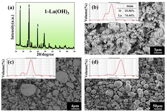
Figure 1.
(a) XRD image of La(OH)3 powder, (b) micro-morphology and particle size distribution of La(OH)3 powder, (c) micro-morphology and particle size distribution of Al2O3 powder, (d) micro-morphology and particle size distribution of SiO2 powder.
The purpose of this study was to investigate the feasibility of replacing EC95 with rare-earth-containing compounds for investment casting-facing materials. The physical parameters of silica sol, defoamers and wetting agents required to configure the facing slurry in the experiment are listed in Table 1. The composition of the CMSX-4 alloy return material is shown in Table 2.

Table 1.
Physical property parameters of silica sol, defoamer, and wetting agent.

Table 2.
Chemical composition of CMSX-4 alloy (wt.%).
2.2. Sintering Process of Ceramic Powder
Figure 2 shows the TG-DSC (Thermogravimetry-Differential Scanning Calorimetry) curve in the air atmosphere after mixing La2O3 and Al2O3. Figure 2 shows that endothermic peaks occur at about 300 °C and 500 °C, with mass losses of about 3.52% and 1.14%. This corresponded to the two-step dehydration process of La(OH)3 (Equations (1) and (2)). At about 1300 °C, an exothermic peak and mass loss were observed, indicating that the formation of LaAlO3 occurred at about 1300 °C, as shown in Equation (3) [23].
La(OH)3 = LaOOH + H2O
2LaOOH = La2O3 + H2O
La2O3 + Al2O3 = 2LaAlO3
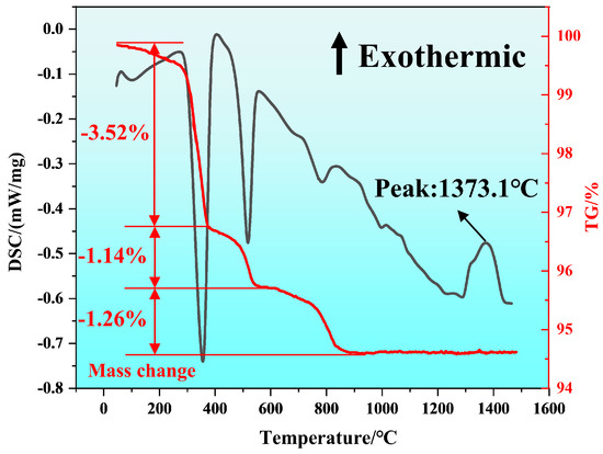
Figure 2.
TG−DSC curves of the powder mixture from La2O3 and Al2O3.
The TG-DSC curve in Figure 2 showed that the pyrolysis process in air after the mixing of La2O3 and Al2O3 could be divided into two stages. As shown in Figure 3, the sample was first heated to 50 °C and held for 60 min. Finally, the temperature was raised to 900 °C, 1000 °C, 1100 °C, 1200 °C, 1300 °C, 1400 °C, and 1500 °C, respectively, with different colored lines used to distinguish between them. The samples were held at each temperature for 2 h, and the heating rate for sintering the samples was 2 °C/min.
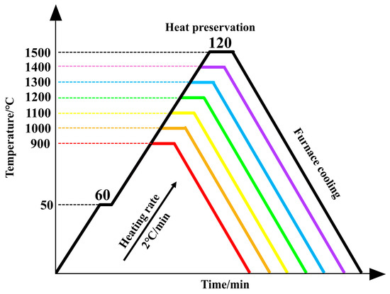
Figure 3.
Sintering regime curve diagram.
2.3. Preparation of Ceramic Shell
The slurry ratios and process parameters used in the experiment are shown in Table 3. Among them, EC95 is an alumina sand produced by Guizhou Dazhong Seventh Grinding Wheel Co., Ltd. in Guizhou, China, containing 95% alumina, 5% silica, and a surface particle size of 60–80 mesh. The ceramic shell was prepared using a layered slurry impregnation and sand grinding process, as shown in Figure 4. After the wax mold was immersed in the pre-prepared surface slurry, the “rain drop method” was used to uniformly disperse the surface sand particles on the sample surface. Subsequently, a fan was activated to accelerate the drying of the initial surface layer. After 1 h, the aforementioned sample was immersed in the back layer slurry to apply a transition sand layer. After drying, a second transition layer was formed. The coating process for the back layer was the same as that for the transition layer, but the back layer required three coats. After the final coating dries, the sample is immersed in the back layer slurry and removed. Once the slurry no longer flows, the fan is activated to seal the slurry. After drying, the wax is removed in a dewaxing pot to obtain the shell mold.

Table 3.
Specific process parameters of the slurry.
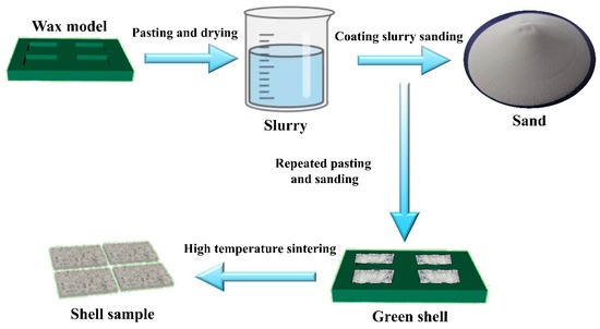
Figure 4.
Flowchart of the ceramic shell preparation method.
2.4. Characterization
The pyrolytic weight loss of the raw materials was characterized using a differential scanning calorimeter (STA449C synchronous thermal analyzer NETZSCH, Selb, Germany) with a heating rate of 10 °C/min 1 from 50 °C to 1500 °C. The flexural strength was evaluated using a three-point bending test instrument (WDW300, Changchun Kexin Testing Instrument Co., Ltd., Changchun, China). Phase analysis was conducted on the raw powders, sintered powders, shell surfaces, and the bottom of the alloy after interfacial reactions using a XRD (Smartlab 9 kW, Rigaku, Tokyo, Japan). The scanning range was set from 10° to 90°, with a scanning speed of 10° per minute. A scanning electron microscope (SEM, Regulus8230HR cold field-emission SEM, Tokyo, Japan) was employed to examine the morphology of the sintered mixed powders, shell surfaces, and alloy after interfacial reactions. And the energy disperse spectroscopy (EDS, Oxford INCA, Oxford, UK) was used to characterize the element distribution in the shell. The viscosity of the slurry was measured using a digital viscometer(NDJ-S, Shenzhen DJS Co., Ltd. Shenzhen, China), with results expressed in mPa·s.
3. Results
3.1. Experimental Data Characterization
3.1.1. Characterization of LaAlO3 Powders
The XRD patterns of the sintered products obtained by mixing La2O3 and Al2O3 in equal amounts are shown in Figure 5. As can be seen from the figure, within the temperature range of 900–1100 °C, no LaAlO3 phase was detected in the sintered product, with the main phases being La(OH)3, La2O3, and Al2O3. As shown in Figure 2, the reaction temperature was below 1300 °C, and Equation (3) did not occur. At this stage, the main process was the two-step dehydration of La(OH)3 (Equations (1) and (2)). When the sintering temperature is further increased to 1200 °C, LaAlO3 begins to appear in the sintered product, but a small amount of La2O3 remains, indicating that the reaction forming LaAlO3 is incomplete. This situation changes when the sintering temperature reaches 1400 °C. When the temperature is increased to 1400 °C, the sintered powder is pure LaAlO3. When the temperature is further increased to 1500 °C, the peak of the sintered product LaAlO3 becomes higher and narrower, indicating better crystallinity of LaAlO3. Therefore, the maximum sintering temperature for LaAlO3 powder is set to 1500 °C as the most appropriate. For convenience, it is abbreviated as LA powder [23].
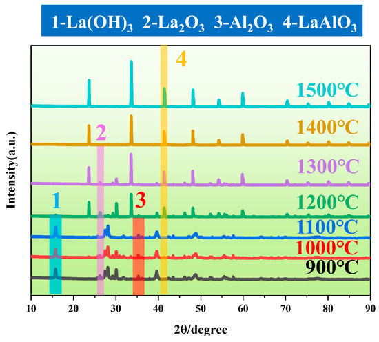
Figure 5.
XRD patterns of the sintered powders at different temperatures.
Further observation of the microstructural morphology of sintered products at different temperatures, combined with Energy-dispersive X-ray spectroscopy (EDS) point-scan analysis (Table 4), reveals that at 1200 °C and 1300 °C, La2O3 particles (box 1) formed by the dehydration of La(OH)3 exhibit a layered stacking structure (highlighted by white boxes in Figure 6a,b), LaAlO3 particles (box 2) are relatively small. As the temperature increases, the layered La2O3 (white boxes) diminishes and is gradually replaced by fine granular LaAlO3 particles (yellow boxes). By 1400 °C, La2O3 particles completely disappear, and LaAlO3 particles grow in size, consistent with XRD results. Analysis of particle distribution (Figure 6c,d) indicates that at lower temperatures, LaAlO3 particles are smaller and form agglomerates with large interparticle gaps. With increasing temperature, agglomeration weakens, resulting in smaller aggregates and narrower gaps. At 1500 °C, LaAlO3 particles no longer agglomerate, displaying a fully developed, densely packed, and nearly gap-free morphology. Comparative size analysis shows that LaAlO3 particles are five times larger than La2O3 particles, demonstrating that elevated temperatures promote both the chemical conversion of La2O3 to LaAlO3 and the coarsening of LaAlO3 grains, ensuring a more complete reaction.

Table 4.
Point sweep results of LA powder.
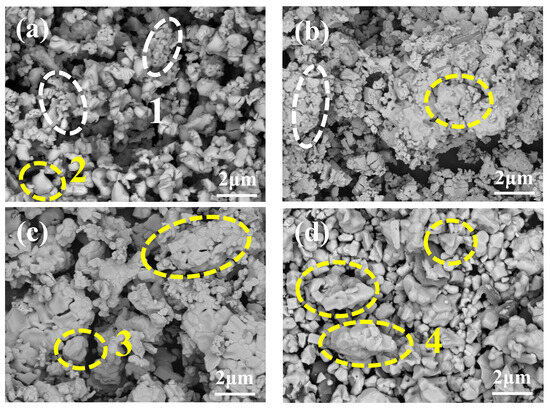
Figure 6.
(a–d) microscopic morphology of the powders after sintering at 1200 °C, 1300 °C, 1400 °C and 1500 °C.
3.1.2. Analysis of Slurry Performance
Figure 7a displays the viscosity curves of slurries prepared by mixing sintered LA powder (sieved through 100-, 200-, and 300-mesh screens) with silica sol at varying powder-to-liquid ratios. The results reveal that as the mesh size increases (i.e., finer particle size), the slurry viscosity gradually decreases under the same powder-to-liquid ratio. At a fixed mesh size, increasing the powder-to-liquid ratio initially causes a rapid rise in viscosity; however, when the ratio exceeds 3.0, the rate of viscosity increase slows and stabilizes. Notably, for 300-mesh powder, adjusting the powder-to-liquid ratio has minimal impact on viscosity. The viscosity of the EC95 surface coating slurry currently in use (green value in Figure 7a) is 901 mPa·s, which is closest to the viscosity (1285 mPa·s) of the slurry prepared using 300-mesh powder, as shown in the green box in the figure.
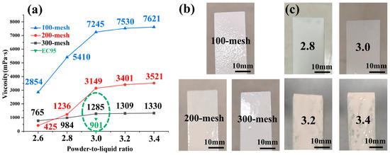
Figure 7.
(a) Viscosity statistics of LA slurry at different mesh and powder/liquid ratios, (b) LA slurry coating effect at different mesh, (c) LA slurry coating effect at different powder/liquid ratios.
Figure 7b presents concrete figures of coatings applied on wax molds using slurries prepared with LA powders of different mesh sizes (100-, 200-, and 300-mesh) at a fixed powder-to-liquid ratio of 3.0. As shown, the sample coated with 100-mesh LA powder exhibits an uneven and bumpy surface. With increasing mesh size (i.e., finer particle size), the surface roughness progressively improves, culminating in a smooth and uniformly covered surface when 300-mesh LA powder is used.
Figure 7c displays physical images of coatings prepared with 300-mesh LA powder at varying powder-to-liquid ratios. The results (Figure 7c) demonstrate that powder-to-liquid ratios of 2.8 and 3.0 yield optimal sag resistance, whereas ratios exceeding 3.0 result in uneven coating thickness and surface irregularities. This degradation occurs because excessively high ratios increase slurry viscosity, complicating the coating process. The primary reason lies in the high density of LA powder: elevated ratios promote sedimentation and reduced fluidity, causing uneven coating deposition and sagging [24].
3.1.3. Analysis of Sintering Properties of LaAlO3 Shells
The prepared LA shells are sintered at different temperatures, and it is found that the highest withstand temperature of LA shells was 1300 °C. Figure 8a,b displays the macroscopic morphology images of LA shells sintered at 1400 °C and 1500 °C. At 1400 °C, surface cracking occurs predominantly at the edges of the shell face coat. Severe surface layer spalling and upward warping of the face coat are observed in shells sintered at 1500 °C, highlighting a significant mismatch between the face coat and transition layer. The fragmented face coat materials from both temperatures are analyzed by XRD, as shown in Figure 8c,d. At 1400 °C, the XRD pattern confirms the presence of LaAlO3 and La2Si2O7 phases, indicating a reaction between LaAlO3 and SiO2 in the face coat to form La2Si2O7. At 1500 °C, additional Al2O3 peaks appear alongside LaAlO3 and La2Si2O7, revealing a secondary reaction product. The reactions can be described as follows:
2LaAlO3 + 2SiO2 = La2Si2O7 + Al2O3
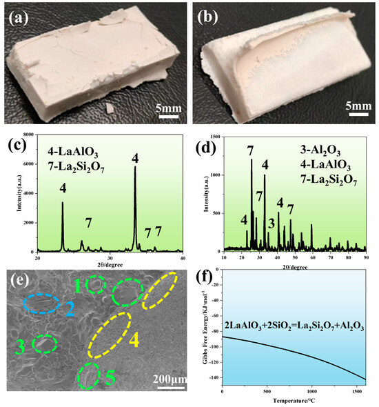
Figure 8.
(a) Macroscopic morphology of LaAlO3 shells after sintering at 1400 °C, (b) LaAlO3 shells after sintering at 1500 °C, (c) XRD image of LaAlO3 shells surface after sintering at 1400 °C, (d) XRD image of LaAlO3 shells surface after sintering at 1500 °C, (e) SEM image of LaAlO3 shells surface after sintering at 1500 °C, and (f) Reactive Gibbs free−energy plots of LaAlO3 and SiO2.
Figure 8e presents the micromorphology of the LA shell surface sintered at 1500 °C. The left region shows the exposed transition layer after face coat spalling, while the right retains the residual face coat. Energy dispersive X-ray spectroscopy (EDS) point analysis (Table 5) shows that the samples with similar compositions in the green boxes (positions 1, 3, and 5) correspond to Al2O3. Newly formed La2Si2O7 phases (blue box 2) are detected near the spalling areas, consistent with XRD results, confirming the reaction between LaAlO3 and SiO2 in the face coat to produce La2Si2O7 and Al2O3. At the edge of the face coat (yellow box 4), LaAlO3 particles aggregate in a contracted configuration, indicating volumetric shrinkage during Equation (2). The presence of La2Si2O7 phases in spalling zones suggests localized stress generation. Furthermore, the structural mismatch between rhombohedral LaAlO3 crystals and monoclinic La2Si2O7 reaction products drives coating delamination and cracking [25,26], as the phase transformation induces interfacial strain. Figure 8f plots the Gibbs free energy (ΔG) of Equation (2). The results show that ΔG progressively decreases with increasing temperature and remains negative across the illustrated temperature range, indicating that Equation (2) proceeds spontaneously within the 0–1600 °C interval. Previous studies report that LaAlO3 reacts with Al2O3 at a 5:1 molar ratio under high temperatures to form LaAl11O18 (Equation (5)). However, neither XRD nor SEM analyses detect LaAl11O18 phases in the LA shells. This absence is attributed to insufficient Al2O3 content near LaAlO3 particles in the face coat to meet the stoichiometric requirement for Equation (3). Furthermore, while lanthanum (La) can react with both Al2O3 and SiO2 at elevated temperatures, thermodynamic preference drives La to preferentially respond with SiO2 over Al2O3 when both coexist in the system [27].
LaAlO3 + 5Al2O3 = LaAl11O18

Table 5.
Point sweep results of LaAlO3 shell after high-temperature sintering.
3.1.4. Characterization of Mixed Powders
The research results indicate that when the temperature exceeds 1300 °C, the LaAlO3 surface layer reacts with SiO2 to form the La2Si2O7 phase, leading to cracking and peeling. To develop a single-crystal shell surface coating material with enhanced high-temperature resistance, two methods were employed. The first method involved adding SiO2 to La2O3 and Al2O3. To prepare a mixed powder of LaAlO3 and La2Si2O7, we added equal proportions of La2O3 and SiO2 to La2O3 and Al2O3 in equal proportions and mixed and sintered them in a molar ratio of 2:1:1 [28]. The addition of La2Si2O7 in the surface layer powder effectively inhibits the progression of Equation (4). The second method involves increasing the Al content based on the reactant ratio of Equation (5), as in the first method. The LaAl11O18 phase can replace the LaAlO3 phase, which is prone to reacting with SiO2, thereby preventing Equation (4) from occurring. The resulting powder exhibits excellent thermal stability.
Figure 9a presents the XRD phase diagrams of mixed powders with La: Al: Si = 2:1:1 sintered at various temperatures. The results show that La10(SiO4)6O3 intermediates and unreacted La2O3 remain in samples sintered at 1350 °C. As the temperature increases, La10(SiO4)6O3 and La2O3 progressively diminish, with complete phase transformation achieved at 1400 °C. Continue to raise the temperature to 1450 °C, and the peaks of the sintered products will be higher and narrower, which means that LaAlO3 and La2Si2O7 have better crystallinity. Therefore, the highest temperature of 1450 °C is most suitable for the sintering process of powder. The final sintered product consists of LaAlO3 and La2Si2O7 phases, meeting design specifications, and is designated as LAS powder. In Figure 9b, the blue circle shows flake-shaped particles, whose composition (point 1) is La2Si2O7, as shown in Table 6. The yellow circle shows small particles agglomerated into spherical particles, whose composition (point 2) is LaAlO3, as shown in Table 6. Figure 9c displays the XRD pattern of mixed powders with adjusted La: Al: Si ratios to 2:11:1, sintered at 1500 °C to eliminate LaAlO3 formation. At this temperature, Reactions 5 and 6 predominantly occur [29,30], yielding sintered products comprising LaAl11O18, La2Si2O7, and Al2O3, designated as LA11S powder. Microstructural and point-scan analyses reveal that smaller granular particles (point 3) correspond to La2Si2O7, while larger polygonal crystals (point 4) represent LaAl11O18.
La2O3 + 5SiO2 = La2Si2O7
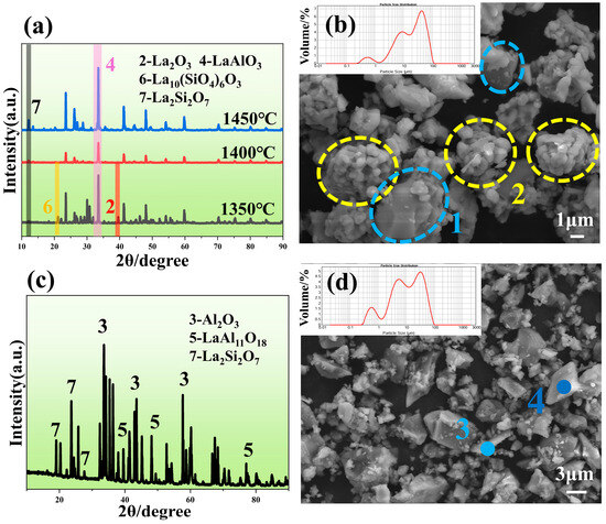
Figure 9.
(a) XRD patterns of powders mixed with equal ratio of La2O3, Al2O3 and SiO2 after sintering at different temperatures, (b) SEM patterns of LAS powders, (c) XRD patterns of LA11S powders after sintering at 1500 °C, and (d) SEM patterns of LA11S powders after sintering at 1500 °C.

Table 6.
Point sweep results of LAS powder.
3.1.5. Comparative Analysis of Three Types of Molds
Figure 10a shows the LA shell sintered at 1300 °C. The shell surface exhibits a light tan color with smoothness and no visible cracks. Microscopic analysis reveals that LaAlO3 particles (point 1 in Figure 10b) are primarily interconnected by a binder, accompanied by abundant pores within the face coat. These pores arise from binder decomposition at high temperatures, which increases porosity. While this enhanced porosity facilitates gas venting during casting and reduces thermal conduction, it simultaneously compromises mechanical strength. Figure 10c displays the LAS shell sintered at 1400 °C, characterized by a uniform white color, smooth surface, and excellent surface quality. Figure 10d shows the microstructure of the LAS shell, where points 2 and 3 correspond to La2Si2O7 and LaAlO3, respectively (Table 7). The particles on the shell surface are densely distributed, and compared to the LA shell, the particle spacing and pore number are significantly reduced. However, the presence of Al2O3 (green box) indicates that LaAlO3 in the surface layer still reacts with SiO2 to form Al2O3 and La2Si2O7. Despite this reaction, the pre-existing La2Si2O7 phase in the LAS shell ensures that the interparticle spacing does not drastically shrink, effectively mitigating excessive crystal structural mismatch. Consequently, the reaction at 1400 °C does not induce face coat cracking or delamination caused by poor phase compatibility.
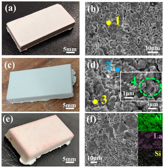
Figure 10.
(a) Macrograph of the LA shell sintered at 1300 °C. (b) SEM image of the LA shell sintered at 1300 °C. (c) Macrograph of the LAS shell sintered at 1400 °C. (d) SEM image of the LAS shell sintered at 1400 °C. (e) Macrograph of the LA11S shell sintered at 1500 °C. (f) SEM image and elemental mapping of the LA11S shell sintered at 1500 °C.

Table 7.
EDS Point analysis results of LA and LAS shells.
Figure 10e shows the LA11S shell sintered at 1500 °C. The face coat appears white with slight reddish edges, exhibiting a smooth and crack-free surface devoid of wrinkles. Figure 10f reveals the microstructure of the LA11S shell. Compared to LA and LAS shells, the LA11S-derived face coat is pore-free and primarily composed of LaAl11O18, Al2O3, and La2Si2O7 phases. The LaAl11O18 particles dominate in size (approximately 12 μm), while Al2O3 grains of varying dimensions cluster around them. This configuration arises because LaAl11O18 inhibits Al2O3 grain growth and mobility via a “pinning effect,” refining the Al2O3 grain size [31,32]. Elemental mapping confirms minimal Si content, with La2Si2O7 localized between LaAl11O18 and Al2O3, acting as a binder. The LA11S shell exhibits exceptional resistance to high-temperature sintering at 1500 °C due to the outstanding thermal stability of LaAl11O18 in the powder. In the magnetoplumbite structure of LaAl11O18, La3+ occupies the oxygen sites within the hexagonal oxygen framework, strongly suppressing ion diffusion. Consequently, this layered compound grows slowly along directions perpendicular to its basal planes, effectively reducing the interfacial separation between the face coat and transition layer and preventing delamination of the LA11S face coat. Moreover, this structural arrangement minimizes voids within the lattice, endowing the LA11S face coat with superior thermal stability [33]. This configuration effectively inhibits oxygen diffusion, reduces oxidation rates, and enhances coating reliability and service life [34].
3.2. Properties and Applications of Ceramic Shells
In investment casting, if the residual strength of the ceramic shell is low, the shell becomes prone to breakage during post-firing handling and furnace loading. Similarly, inadequate resistance to high-temperature deformation can lead to cracking during pouring and reduced dimensional accuracy of the cast part. Therefore, residual strength and high-temperature strength are critical metrics for evaluating the mechanical performance of ceramic shells [35]. Figure 11 compares the residual and high-temperature strengths of LA, LAS, and LA11S shells sintered at 1300 °C, 1400 °C, and 1500 °C, respectively, against EC95 shells sintered under the same conditions. The results show that both residual strength and high-temperature strength of EC95 shells increase with sintering temperature. Since the back layer significantly influences mechanical properties, the strengths of all three shells also exhibit an upward trend. This is attributed to the reaction between Al2O3 and SiO2 in EC95 shells during high-temperature sintering, forming mullite—a crystalline phase with high strength and thermal stability. However, the shells exhibit lower strength values than EC95 due to non-uniform interfacial bonding between their face and transition layers, which promotes crack propagation and compromises mechanical performance.
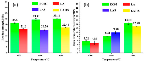
Figure 11.
(a) Residual strength of different shells sintered at different temperatures. (b) High-temperature strength of various shells sintered at different temperatures.
Figure 12a–c displays cross-sectional microstructures near the bottom surfaces of recycled CMSX-4 alloy castings produced using three crucibles fabricated via the shell process. Among them, a1-a3, b1-b3, and c1-c3 are the elemental distribution maps of Ni, Al, and O, respectively. Figure 12a reveals a dark gray layer adhering to the alloy surface. The LA crucible exhibits the thinnest layer (approximately 1 μm) with sparse distribution, while the LAS and LA11S crucibles show thicker, continuous layers of 3 μm and 4 μm, respectively. Elemental mapping confirms that the continuous dark gray phase corresponds to Al2O3, indicating the formation of an alumina-based slag layer on the alloy surface.
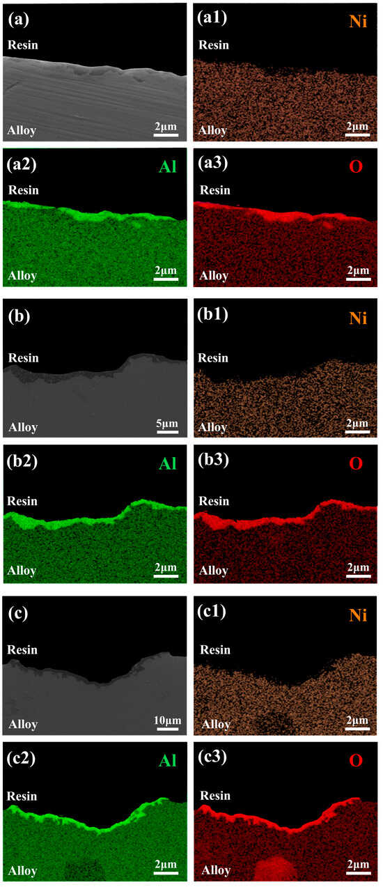
Figure 12.
Cross-sectional microstructures and elemental mapping of recycled CMSX-4 alloy castings produced with: (a) LA shell, (b) LAS shell, (c) LA11S shell. (a1–a3) the elemental distribution maps of Ni, (b1–b3) the elemental distribution maps of Al (c1–c3) the elemental distribution maps of O.
Figure 13a displays the XRD spectra of slag layers on the surfaces of superalloy castings produced using LA, LAS, and LA11S crucibles. The purple and orange bars in the figure represent the presence of Al2O3 and NiO on the surface of the LA11S and LAS crucibles casting alloys, respectively, while the blue bar represents the presence of LaAlO3 on the surface of the LA crucible casting alloy. The results reveal distinct compositional differences: Al2O3 and LaAlO3 dominate the surface of the LA crucible-cast alloy, while Al2O3 and NiO are observed for the LAS crucible, and Al2O3, SiO2, and NiO coexist in the LA11S crucible-cast alloy. The presence of LaAlO3 on the LA crucible-derived surface is attributed to partial spalling of the LA crucible during molten alloy interaction caused by its inferior high-temperature strength. These dislodged LaAlO3 particles adhere to the alloy surface upon solidification.
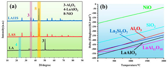
Figure 13.
(a) XRD patterns of the bottom regions of CMSX−4 alloy castings produced using three shells (LA, LAS, LA11S), (b) Ellingham diagrams for LaAl11O18, LaAlO3, La2Si2O7, Al2O3, SiO2 and NiO.
Figure 13b illustrates the Ellingham plots for LaAl11O18, LaAlO3, La2Si2O7, Al2O3, SiO2 and NiO. The thermodynamic stability of these oxides under superalloy casting conditions is in the order of LaAl11O18 > LaAlO3 > La2Si2O7 > Al2O3 > SiO2 > NiO, which is evidenced by their relative positions in the graph. This indicates that LaAl11O18, LaAlO3 and La2Si2O7 exhibit higher thermodynamic stability than NiO. Therefore, theoretically, the LA, LAS and LA11S material shells do not react with pure Ni melt. However, the dissolution and decomposition of silica sol (SiO2) in the melt of these three crucible materials can introduce oxygen contamination to the Ni melt [36,37]. It is noteworthy that the addition of reactive elements such as Al to the alloys significantly increases their oxygen affinity under these conditions compared to Ni and Si. Al reacts with the oxygen released from the decomposition of SiO2 in the crucible to form a more stabilized Al2O3, which accelerates the dissolution of the crucibles and exacerbates the oxygen contamination in the alloy melt, as shown in the following reaction. The schematic diagram of the interface reaction between the ceramic shell and the alloy is shown in Figure 14.

Figure 14.
Schematic diagram of interface reaction.
The study of the surface quality of the shells at different sintering temperatures shows that the SiO2 in the silica sol in the surface layer of the LA crucible reacts with LaAlO3 to form La2Si2O7, which is less prone to be dissolved and decomposed in the melt, whereas there is more silica sol in the surface layer of the sintered crucible because of replacement of the surface layer material in the LAS and LA11S crucibles, which explains why The Al2O3 layer on the surface of the cast alloy is the thinnest in the LA crucible among the three crucibles, while the LAS and LA11S crucibles have the thickest slag floats. During the melting process, the superalloy melt interacts with the inner wall of the crucible, leading to the rapid formation of Al2O3 phases at the interface. These Al2O3 particles rise under gravity to form a slag layer. Given the intimate contact between the superalloy melt and the LAS, LA11S crucible substrates, even if interfacial reactions occur, the resulting Al2O3 should exhibit a continuous and uniform distribution. In comparison, Han and co-workers [30] found that the reaction layer in the CMSX-4 alloy cast using an Al2O3-type shell was relatively uniform, with a flat and porous interface between the reaction layer and the alloy. However, the slag thickness was approximately 25 μm, which is significantly thicker than the interface reaction layer thickness (no more than 5 μm) observed after casting with LA, LAS, and LA11S-type shells. This indicates a more intense interface reaction. Xuan and co-workers [38] investigated the interface reaction between CMSX-4 and silicon dioxide ceramics. Experimental results showed that a continuous Al2O3 layer and discontinuous tantalum/titanium-enriched carbide layers formed at the interface. Compared to the reaction products after casting with LA, LAS, and LA11S-type shells, the reaction products were more complex. The Al2O3 layer obtained from the substitution reaction between Al and SiO2 serves as a nucleation seed for (Ta/Ti)C carbides at the CMSX-4 alloy interface, further intensifying the reaction. In summary, LA, LAS, and LA11S shell-casting nickel-based high-temperature alloys exhibit weaker interfacial reactions and generate more singular reactants, making them a promising new type of shell material with significant application prospects.
4. Conclusions
- This study investigated the sintering of LaAlO3 powder, the properties of the prepared surface slurry, and the refractoriness of the composite shell. The refractoriness of the composite shell was improved by introducing La2Si2O7 and LaAl11O18 to replace LaAlO3. Three types of shells were used to cast CMSX-4 alloy, and the interface reactions were observed. The study employed scanning electron microscopy (SEM), energy dispersive spectroscopy (EDS), and X-ray diffraction (XRD) to assess the microstructure and phase composition of the powders, shell surfaces, and interfaces after alloy casting. The main findings and conclusions are summarized as follows: The La2O3-Al2O3 system yields high-purity LaAlO3 powder when sintered at 1500 °C. A slurry with a powder-to-liquid ratio of 3:1 and 300-mesh particle size demonstrates optimal coating performance, forming a shell that remains crack-free at 1300 °C. However, at temperatures exceeding 1400 °C, LaAlO3 reacts with SiO2 to generate La2Si2O7 and Al2O3, leading to failure of the face coat due to lattice distortion and volumetric shrinkage.
- Through optimization of the La2O3-Al2O3-SiO2 ternary ratio, the LAS shell, containing a La2Si2O7 phase in its face coat, buffers thermal stress and remains crack-free at 1400 °C. Meanwhile, the LA11S shell exhibits a layered LaAl11O18 structure that suppresses oxygen diffusion and grain coarsening. At 1500 °C, this shell maintains excellent surface quality, meeting the stringent requirements for single-crystal superalloy casting applications.
- After casting CMSX-4 recycled material with LA crucibles, spalled LaAlO3 particles adhere to the alloy surface, while LAS and LA11S shells exhibit NiO formation. All three crucibles develop Al2O3 slag layers with thicknesses below 5 μm. Notably, no severe interfacial reactions occur between the crucibles and the alloy melt; instead, only dissolution-dominated interactions are observed.
In summary, the composite shells prepared from LA, LAS, and LA11S powders can withstand temperatures above 1300 °C and have certain mechanical properties. After casting nickel-based high-temperature alloys, the reaction phenomenon at the interface is weak, exhibiting excellent thermodynamic stability and chemical stability. They are suitable for use in the surface layer of ceramic shells to inhibit interface reactions and obtain alloys with good surface quality. Additionally, this study has not yet conducted more detailed adjustments to the introduction ratios of La2Si2O7 and LaAl11O18. In subsequent research, reducing the introduction of La2Si2O7 and increasing the proportions of LaAl11O18 and Al2O3 will facilitate further reduction in the thickness of the slag reaction layer and minimize interfacial reactions during the crucible casting of DZ22 alloy using the newly prepared powder system. Furthermore, the powder prepared in this study was only used as the surface layer in the composite shell for research purposes. Future studies could explore using the experimentally prepared slurry for coating the transition layer and back layer, thereby enhancing the mechanical properties of the shell by achieving a more compact bond between the layers.
Author Contributions
Methodology, M.L.; investigation, M.L.; writing—original draft preparation, M.L.; writing—review and editing, J.Y., X.L. and Z.Y.; visualization, Z.R. and X.Z.; supervision, Z.R.; software, X.Z. All authors have read and agreed to the published version of the manuscript.
Funding
This work was financially supported by the National Key Research and Development Program of China (2024 YFB3713802) and the Shanghai Collaborative Innovation Project (HCXBCY-2024-030).
Data Availability Statement
Data are available from the authors upon request
Conflicts of Interest
The authors declare no conflict of interest.
References
- Li, Y.; Tan, Y.; Wang, D.; Li, P.; Chen, Z.; Zhao, J.; Qiang, J. Effect of trace impurity elements on the wettability and interfacial reaction between DZ125 alloy and ceramic shell. Corros. Sci. 2023, 221, 111370. [Google Scholar] [CrossRef]
- Xia, W.; Zhao, X.; Yue, L.; Zhang, Z. A review of composition evolution in Ni-based single crystal superalloys. J. Mater. Sci. Technol. 2020, 44, 76–95. [Google Scholar] [CrossRef]
- Wang, H.; Shang, G.; Liao, J.; Yang, B.; Yuan, C. Experimental investigations and thermodynamic calculations of the interface reactions between ceramic moulds and Ni-based single-crystal superalloys: Role of solubility of Y in the LaAlO3 phase. Ceram. Int. 2018, 44, 7667–7673. [Google Scholar] [CrossRef]
- Yao, J.S.; Dong, L.P.; Wang, L.L.; Yang, S.; Yang, W.; Wang, Z.L.; Shen, B. Interface reaction between DD6 single crystal superalloy and Ceramic Core. In Proceedings of the Materials Science Forum; Trans Tech Publications Ltd.: Bäch, Switzerland, 2021; pp. 297–304. [Google Scholar]
- Li, Q.; Song, J.; Wang, D.; Yu, Q.; Xiao, C. Effect of Cr, Hf and temperature on interface reaction between nickel melt and silicon oxide core. Rare Met. 2011, 30, 405–409. [Google Scholar] [CrossRef]
- Rabah, M.; Ewais, E.M.M. Multi-impregnating pitch-bonded Egyptian dolomite refractory brick for application in ladle furnaces. Ceram. Int. 2009, 35, 813–819. [Google Scholar] [CrossRef]
- Li, X.; Zhao, Y.; Wang, L.; Long, X.; Chen, C.; Qin, Z. Study on the stability of different refractories during the melting process of a K4169 Ni-based superalloy. Ceram. Int. 2023, 49, 29573–29583. [Google Scholar] [CrossRef]
- Pisarski, W.A. Rare Earth Doped Glasses/Ceramics: Synthesis, Structure, Properties and Their Optical Applications. Materials 2022, 15, 8099. [Google Scholar] [CrossRef] [PubMed]
- Xia, C.; Cai, Y.; Ma, Y.; Wang, B.; Zhang, W.; Karlsson, M.; Wu, Y.; Zhu, B. Natural Mineral-Based Solid Oxide Fuel Cell with Heterogeneous Nanocomposite Derived from Hematite and Rare-Earth Minerals. ACS Appl. Mater. Interfaces 2016, 8, 20748–20755. [Google Scholar] [CrossRef] [PubMed]
- Rao, R.R.; Mariappan, L. Combustion synthesis and characterisation of lanthanum hexa-aluminate. Adv. Appl. Ceram. 2013, 104, 268–271. [Google Scholar] [CrossRef]
- Lee, M.-H.; Jung, W.-S. Facile synthesis of LaAlO3 and Eu(II)-doped LaAlO3 powders by a solid-state reaction. Ceram. Int. 2015, 41, 5561–5567. [Google Scholar] [CrossRef]
- Liu, Q.; Chang, Q.; Li, J.; You, Z.; Peng, J.; Chen, J. Infrared radiation performance and calculation of B-site doped lanthanum aluminate from first principles. Ceram. Int. 2018, 44, 11570–11575. [Google Scholar] [CrossRef]
- Ianoş, R.; Lazău, R.; Borcănescu, S.; Băbuță, R. Single-step combustion synthesis of LaAlO3 powders and their sintering behavior. Ceram. Int. 2014, 40, 7561–7565. [Google Scholar] [CrossRef]
- Chandradass, J.; Balasubramanian, M.; Kim, K.H. Synthesis and Characterization of LaAlO3 Nanopowders by Various Fuels. Mater. Manuf. Process. 2010, 25, 1449–1453. [Google Scholar] [CrossRef]
- Chen, H.; Yang, C.; Zhang, J.; He, W.; Liao, Y.; Zhang, Q.; Zheng, S.; Lei, G. High performance distributed CPW phase shifters with etched BST thin films on Φ 3″ LaAlO3 substrates. Solid State Sci. 2012, 14, 117–120. [Google Scholar] [CrossRef]
- Cinibulk, M.K. Thermal stability of some hexaluminates at 1400 °C. J. Mater. Sci. Lett. 1995, 14, 651–654. [Google Scholar] [CrossRef]
- Reddy, S.P.; Sairam, Y.N.V.; Shaik, M.H.; Kumar, P.R.; Yamini, T.; Saisree, M.M.; Raju, N. Preparation and Experimental Investigation of Lanthanum Hexa-Aluminate Calcinated Powders. Ann. Chim.-Sci. Matériaux 2025, 49, 63–70. [Google Scholar] [CrossRef]
- Iketani, K.; Yoshinaka, M.; Hirota, K.; Yamaguchi, O. Low-temperature synthesis and sintering of LaAlO3. J. Mater. Sci. Lett. 2001, 20, 2045–2046. [Google Scholar] [CrossRef]
- John Berchmans, L.; Angappan, S.; Visuvasam, A.; Ranjith Kumar, K.B. Preparation and characterization of LaAlO3. Mater. Chem. Phys. 2008, 109, 113–118. [Google Scholar] [CrossRef]
- Li, A.-D.; Shao, Q.-Y.; Ling, H.-Q.; Cheng, J.-B.; Wu, D.; Liu, Z.-G.; Ming, N.-B.; Wang, C.; Zhou, H.-W.; Nguyen, B.-Y. Characteristics of LaAlO3 gate dielectrics on Si grown by metalorganic chemical vapor deposition. Appl. Phys. Lett. 2003, 83, 3540–3542. [Google Scholar] [CrossRef]
- Rizwan, M.; Gul, S.; Iqbal, T.; Mushtaq, U.; Farooq, M.H.; Farman, M.; Bibi, R.; Ijaz, M. A review on perovskite lanthanum aluminate (LaAlO3), its properties and applications. Mater. Res. Express 2019, 6, 112001. [Google Scholar] [CrossRef]
- Li, X.; Li, Z.; Zhu, Y. Effect of CoO–NiO additives on the microstructure and mechanical properties of microcrystalline corundum abrasives with in-situ formed needle-shaped LaAl11O18. Ceram. Int. 2022, 48, 33794–33800. [Google Scholar] [CrossRef]
- Mühler, T.; Gomes, C.M.; Heinrich, J.; Günster, J. Slurry-Based Additive Manufacturing of Ceramics. Int. J. Appl. Ceram. Technol. 2013, 12, 18–25. [Google Scholar] [CrossRef]
- Neto, R.; Duarte, T.; Alves, J.L.; Torres, F. Experimental characterization of ceramic shells for investment casting of reactive alloys. Ciência Tecnol. Dos Mater. 2017, 29, e34–e39. [Google Scholar] [CrossRef]
- Venkat, Y.; Choudary, K.R.; Chatterjee, D.; Das, D.K.; Pandey, A.K.; Singh, S. Development of mullite-alumina ceramic shells for precision investment casting of single-crystal high-pressure turbine blades. Ceram. Int. 2022, 48, 28199–28206. [Google Scholar] [CrossRef]
- Zhao, D.; Su, H.; Hao, S.; Shen, Z.; Liu, Y.; Guo, Y.; Yang, P.; Zhang, Z.; Guo, M. Excellent thermal stability of nanostructured Al2O3–Y3Al5O12–ZrO2 eutectic ceramic composites by high-speed directional solidification. Compos. Part B Eng. 2023, 266, 111035. [Google Scholar] [CrossRef]
- Tzvetkov, G.; Minkova, N. Application of mechanochemical treatment to the synthesis of A-and G-forms of La2Si2O7. Solid State Ion. 1999, 116, 241–248. [Google Scholar] [CrossRef]
- Kokini, K.; DeJonge, J.; Rangaraj, S.; Beardsley, B. Thermal shock of functionally graded thermal barrier coatings with similar thermal resistance. Surf. Coat. Technol. 2002, 154, 223–231. [Google Scholar] [CrossRef]
- Kvernes, I.; Forseth, S. Corrosion mechanisms of ceramic coatings in diesel engines. Mater. Sci. Eng. 1987, 88, 61–67. [Google Scholar] [CrossRef]
- Weihao, H.; Jianbo, Y.; Zhongming, R. Effect of La on Mould Wettability and Interfacial Reaction between CMSX-4 Single Crystal Alloy and Ceramic Mould. Spec. Steel 2024, 45, 104. [Google Scholar]
- Wu, Y.-Q.; Zhang, Y.-F.; Wang, S.-W.; Guo, J.-K. In-situ synthesis of rodlike LaAl11O18 in Al2O3 powder by a coprecipitation method. J. Eur. Ceram. Soc. 2001, 21, 919–923. [Google Scholar] [CrossRef]
- Negahdari, Z.; Willert-Porada, M.; Pfeiffer, C. Mechanical properties of dense to porous alumina/lanthanum hexaaluminate composite ceramics. Mater. Sci. Eng. A 2010, 527, 3005–3009. [Google Scholar] [CrossRef]
- Machida, M.; Eguchi, K.; Arai, H. Analytical Electron Microscope Analysis of the Formation of BaO·6Al2O3. J. Am. Ceram. Soc. 2005, 71, 1142–1147. [Google Scholar] [CrossRef]
- Gadow, R.; Lischka, M. Lanthanum hexaaluminate—Novel thermal barrier coatings for gas turbine applications—Materials and process development. Surf. Coat. Technol. 2002, 151–152, 392–399. [Google Scholar] [CrossRef]
- Chen, B.; Liu, J. Residual strength of hybrid-fiber-reinforced high-strength concrete after exposure to high temperatures. Cem. Concr. Res. 2004, 34, 1065–1069. [Google Scholar] [CrossRef]
- Lapin, J.; Gabalcová, Z.; Pelachová, T. Effect of Y2O3 crucible on contamination of directionally solidified intermetallic Ti–46Al–8Nb alloy. Intermetallics 2011, 19, 396–403. [Google Scholar] [CrossRef]
- Saha, R.; Nandy, T.; Misra, R.; Jacob, K. Evaluation of the reactivity of titanium with mould materials during casting. Bull. Mater. Sci. 1989, 12, 481–493. [Google Scholar] [CrossRef]
- Xuan, W.; Du, L.; Song, G.; Zhang, X.; Zhang, H.; Ren, Z. Some new observations on interface reaction between nickel-based single crystal superalloy CMSX-4 and silicon oxide ceramic core. Corros. Sci. 2020, 177, 108969. [Google Scholar] [CrossRef]
Disclaimer/Publisher’s Note: The statements, opinions and data contained in all publications are solely those of the individual author(s) and contributor(s) and not of MDPI and/or the editor(s). MDPI and/or the editor(s) disclaim responsibility for any injury to people or property resulting from any ideas, methods, instructions or products referred to in the content. |
© 2025 by the authors. Licensee MDPI, Basel, Switzerland. This article is an open access article distributed under the terms and conditions of the Creative Commons Attribution (CC BY) license (https://creativecommons.org/licenses/by/4.0/).