
Investigating the Bond Performance of FRP Bars and Concrete Under Dynamic Loading Conditions


Abstract
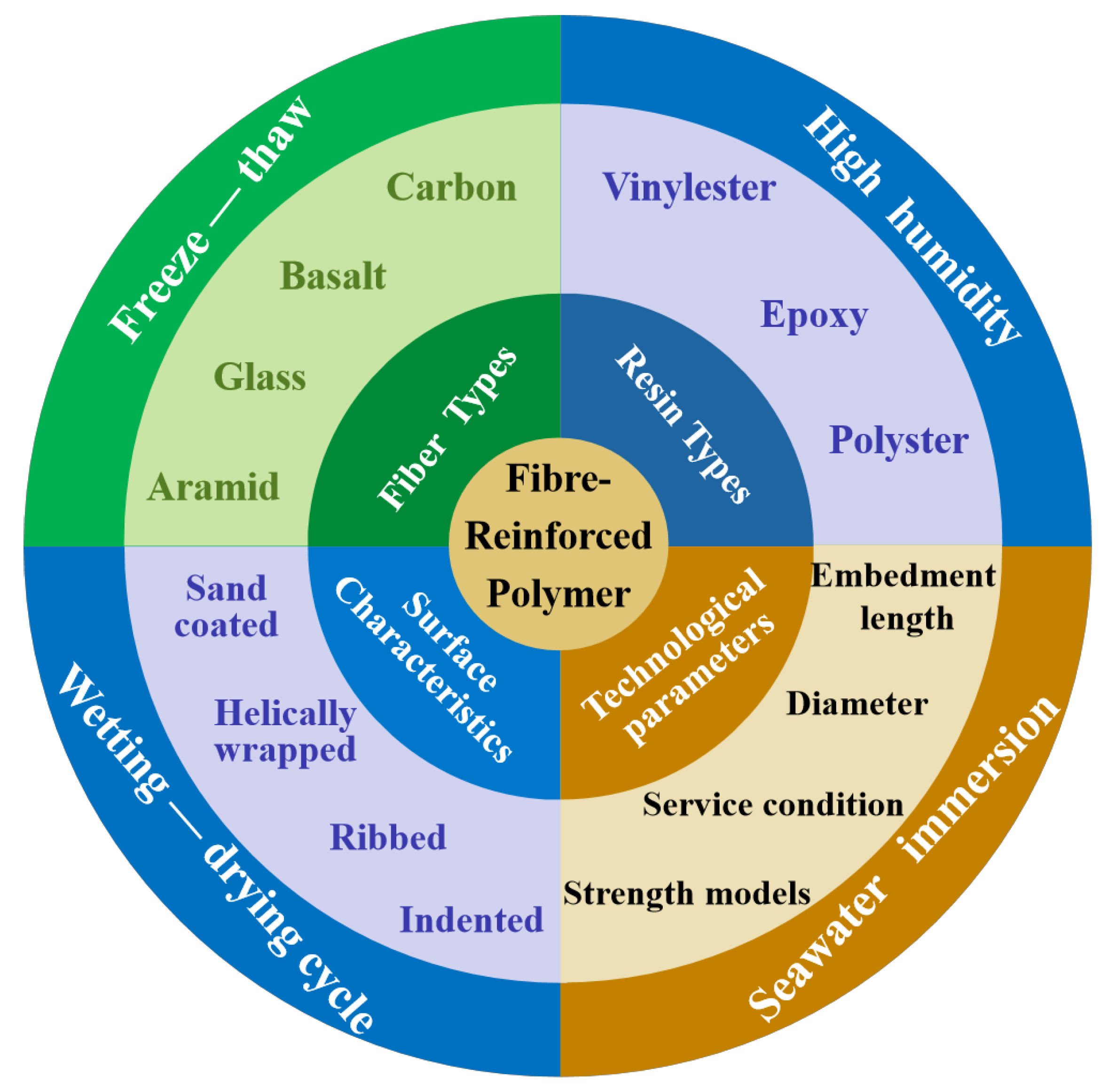
1. Introduction
2. Materials and Methods
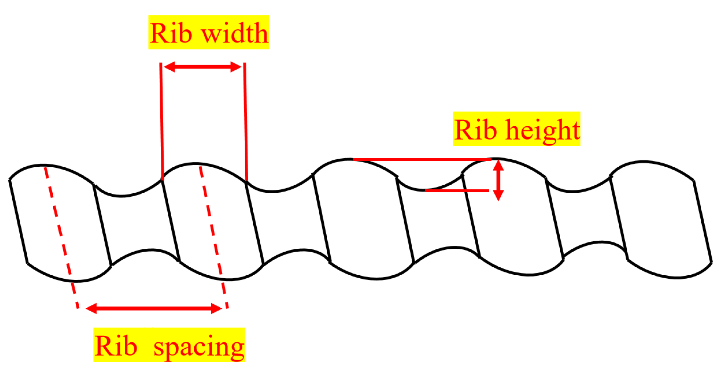
2.1. Materials
2.2. Specimen Preparation
2.3. Micro-Morphology and Surface Roughness Tests
2.4. EDX Analysis
2.5. Pull-Out Test
3. Results
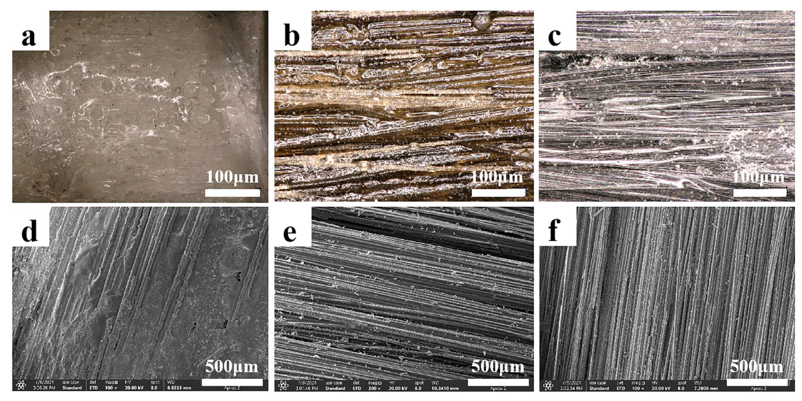
3.1. Bar Surface Morphology
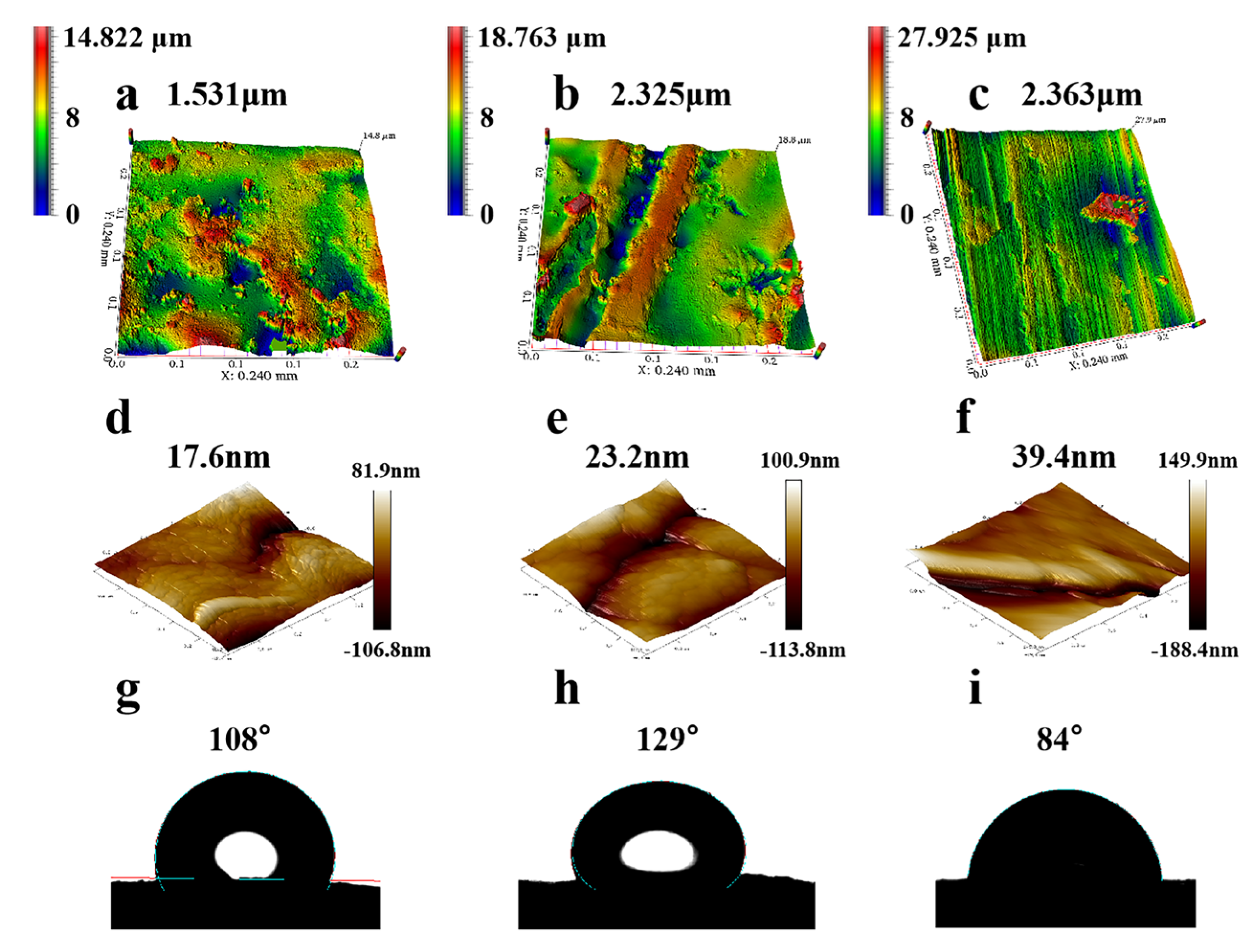
3.2. Bar Surface Roughness and Water Contact Angle
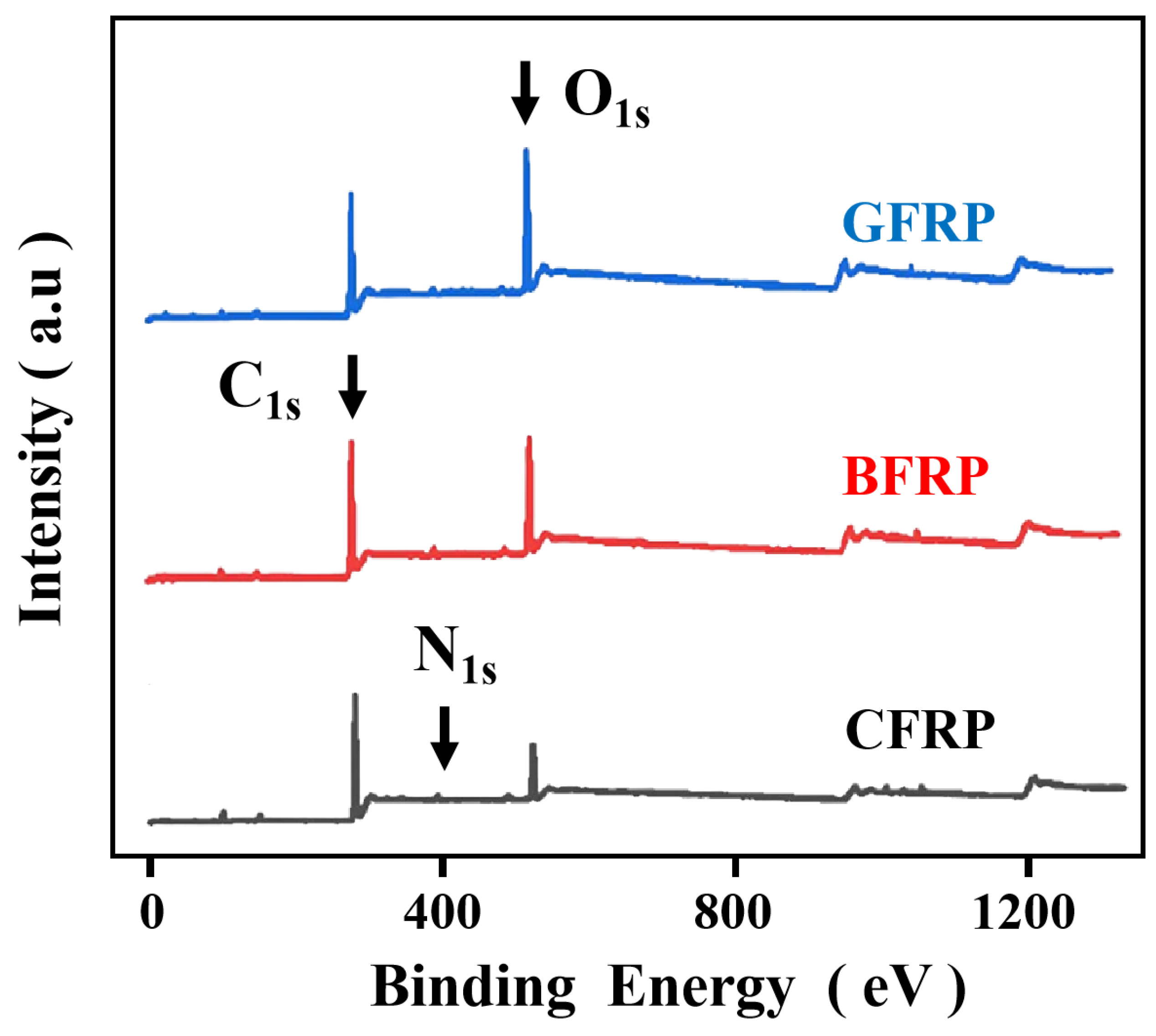
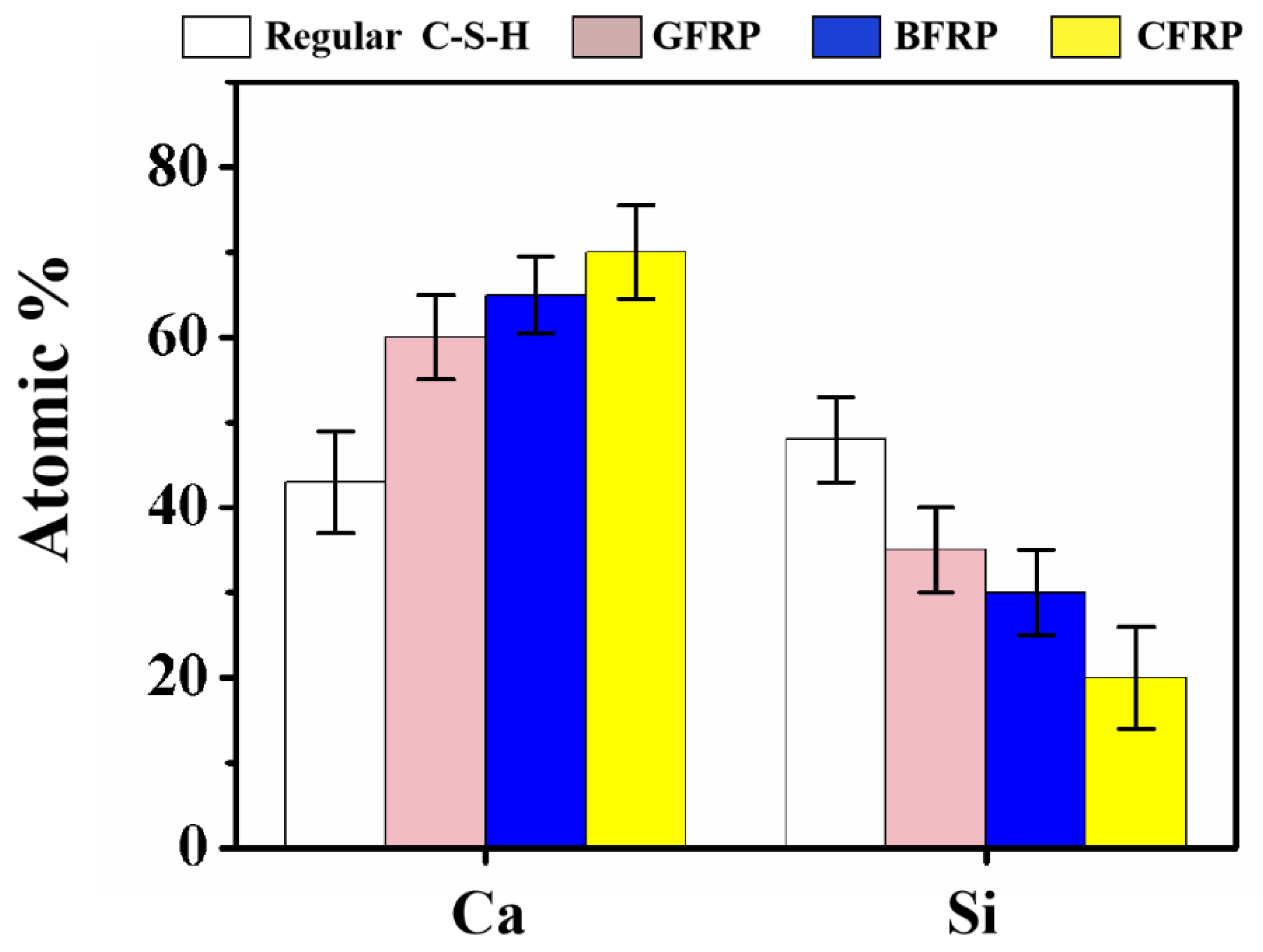
3.3. The Chemical Composition of the Bar and Its Interfacial Properties with Cement
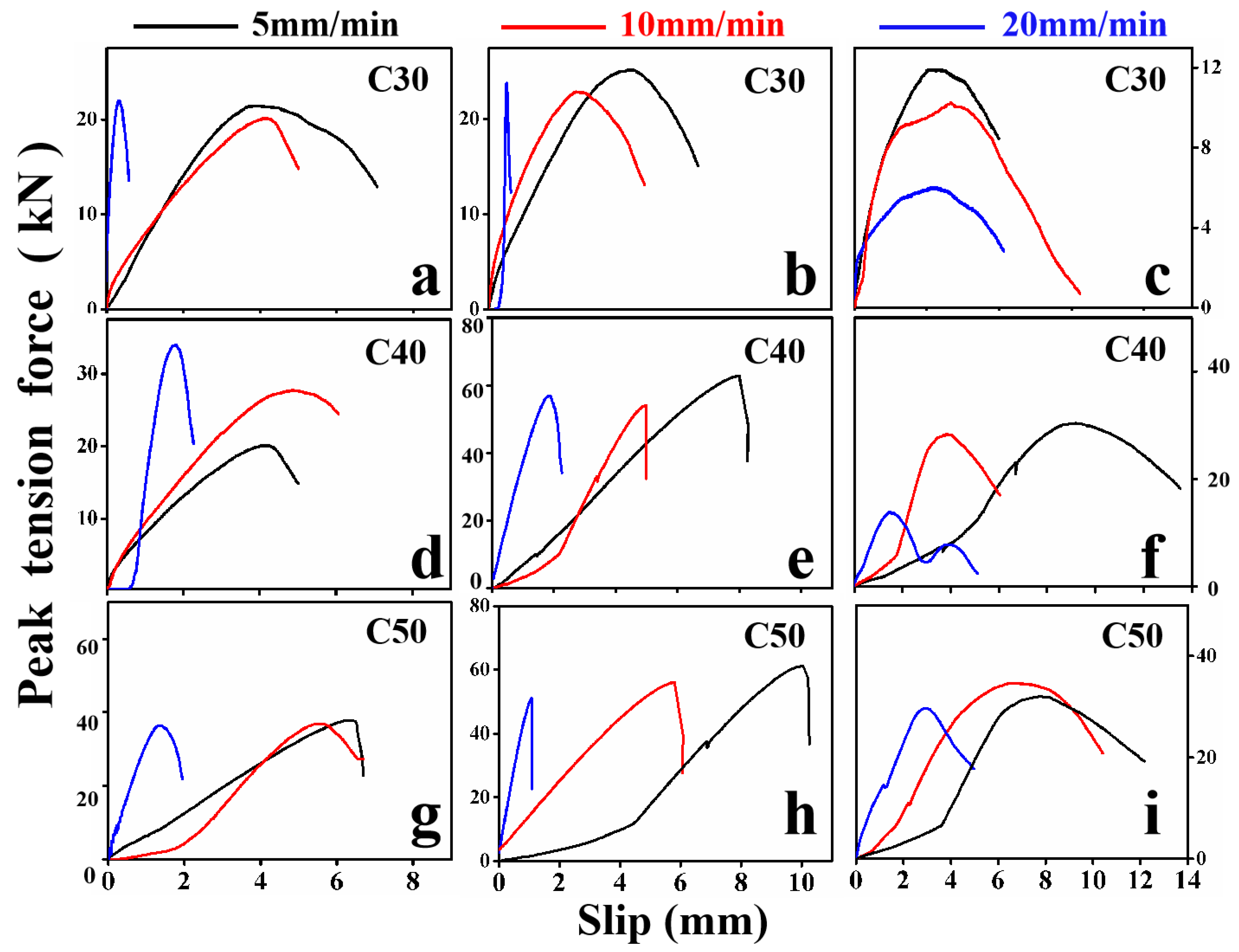
3.4. Bond Peak Tension Force–Slip Curves of the FRP Bar–Concrete Interface
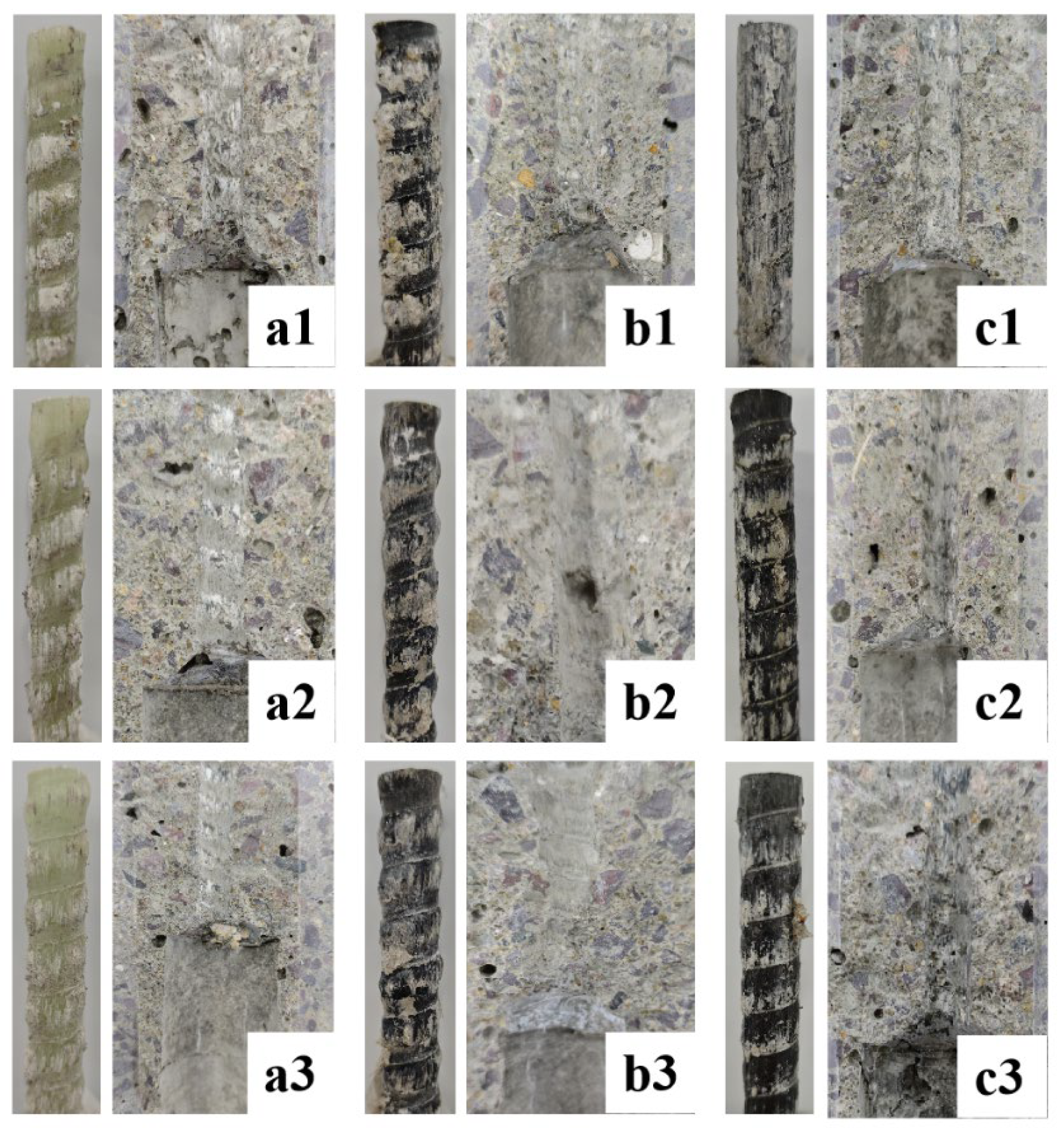
3.5. Interfacial Bond Failure Modes
4. Conclusions
- The wettability of the FRP bars’ surface is determined by the roughness and chemical composition. The results show that the WCA of the CFRP bars is the highest, reaching 84°.
- The surface of the FRP bars is primarily composed of three chemical elements: carbon, hydrogen, and oxygen. The O/C ratio of the CFRP bars is the highest, reaching 31.20. Firstly, the higher this value is, the stronger the surface polarity and hydrophilicity, which helps enhance the bonding strength. Secondly, the surface hydrophilicity aids in the formation of the covalent bond to C–S–H.
- The results of the pull-out tests indicate that under C50 concrete conditions, the BFRP bars exhibited the highest bond strength of 27.51 MPa at a loading rate of 5 mm/min. This is due to their deeper rib structure, which enhances mechanical interlocking with concrete.
- As the loading rate increases, the bonding strength of the FRP bars generally shows a decreasing trend. Under dynamic loading at 20 mm/s, the bond strength of the BFRP bars in C30, C40, and C50 concrete decreases by 9.4%, 5.1%, and 15.17%, respectively, compared to static conditions. The CFRP bars exhibit a more pronounced reduction in bond strength, ranging from 5% to 43%. This decrease is primarily due to the introduction of dynamic factors, which result in an uneven stress distribution. Consequently, this leads to a reduction in deformation and a decrease in the proportion of mechanical interlock.
- FRP bars can extend the lifespan of concrete structures and reduce maintenance costs, but the environmental issues caused by their non-biodegradability, along with the high initial cost and the lack of technical standards, limit their widespread application. Technological advancements are needed to address the economic and environmental challenges, thereby promoting sustainable development.
- FRP bars offer advantages such as corrosion resistance, lightweight properties, and high durability, making them suitable for harsh environments like coastal or industrial areas. However, their high cost and the uncertainty regarding their long-term performance limit their widespread application, requiring further research breakthroughs.
Supplementary Materials
Author Contributions
Funding
Institutional Review Board Statement
Informed Consent Statement
Data Availability Statement
Conflicts of Interest
References
- Zhang, K.; Zhang, Q.; Xiao, J. Durability of FRP bars and FRP bar reinforced seawater sea sand concrete structures in marine environments. Constr. Build. Mater. 2022, 350, 128898. [Google Scholar] [CrossRef]
- Zwicky, D. Mechanical properties of organic-based lightweight concretes and their impact on economic and ecological performances. Constr. Build. Mater. 2020, 245, 118413. [Google Scholar] [CrossRef]
- Sangmesh, B.; Patil, N.; Jaiswal, K.K.; Gowrishankar, T.; Selvakumar, K.K.; Jyothi, M.; Jyothilakshmi, R.; Kumar, S. Development of sustainable alternative materials for the construction of green buildings using agricultural residues: A review. Constr. Build. Mater. 2023, 368, 130457. [Google Scholar] [CrossRef]
- Benmokrane, B.; Elgabbas, F.; Ahmed, E.A.; Cousin, P. Characterization and Comparative Durability Study of Glass/Vinylester, Basalt/Vinylester, and Basalt/Epoxy FRP Bars. J. Compos. Constr. 2015, 19, 04015008. [Google Scholar] [CrossRef]
- Reis, E.; de Azevedo, R.; Christoforo, A.; Poggiali, F.; Bezerra, A. Bonding of steel bars in concrete: A systematic review of the literature. Structures 2023, 49, 508–519. [Google Scholar] [CrossRef]
- Fang, C.; Lundgren, K.; Plos, M.; Gylltoft, K. Bond behaviour of corroded reinforcing steel bars in concrete. Cem. Concr. Res. 2006, 36, 1931–1938. [Google Scholar] [CrossRef]
- Liang, X.; Peng, J.; Ren, R. A state-of-the-art review: Shear performance of the concrete beams reinforced with FRP bars. Constr. Build. Mater. 2022, 364, 129996. [Google Scholar] [CrossRef]
- Ji, X.-L.; Chen, L.-J.; Liang, K.; Pan, W.; Su, R.K.-L. A review on FRP bars and supplementary cementitious materials for the next generation of sustainable and durable construction materials. Constr. Build. Mater. 2023, 383, 131403. [Google Scholar] [CrossRef]
- Hosseini, S.-A.; Nematzadeh, M.; Chastre, C. Prediction of shear behavior of steel fiber-reinforced rubberized concrete beams reinforced with glass fiber-reinforced polymer (GFRP) bars. Compos. Struct. 2021, 256, 113010. [Google Scholar] [CrossRef]
- Less, T.; Demir, A.; Sezen, H. Structural performance and corrosion resistance of fiber reinforced polymer wrapped steel reinforcing bars. Constr. Build. Mater. 2022, 366, 130176. [Google Scholar] [CrossRef]
- Attia, M.M.; Ahmed, O.; Kobesy, O.; Malek, A.S. Behavior of FRP rods under uniaxial tensile strength with multiple materials as an alternative to steel rebar. Case Stud. Constr. Mater. 2022, 17, e01241. [Google Scholar] [CrossRef]
- Sijavandi, K.; Sharbatdar, M.K.; Kheyroddin, A. Experimental evaluation of flexural behavior of High-Performance Fiber Reinforced Concrete Beams using GFRP and High Strength Steel Bars. Structures 2021, 33, 4256–4268. [Google Scholar] [CrossRef]
- Sun, L.; Wang, C.; Zhang, C.; Yang, Z.; Li, C.; Qiao, P. Experimental investigation on the bond performance of sea sand coral concrete with FRP bar reinforcement for marine environments. Adv. Struct. Eng. 2022, 26, 533–546. [Google Scholar] [CrossRef]
- Xiong, Z.; Wei, W.; Liu, F.; Cui, C.; Li, L.; Zou, R.; Zeng, Y. Bond behaviour of recycled aggregate concrete with basalt fibre-reinforced polymer bars. Compos. Struct. 2021, 256, 113078. [Google Scholar] [CrossRef]
- Xiong, Z.; Mai, G.; Qiao, S.; He, S.; Zhang, B.; Wang, H.; Zhou, K.; Li, L. Fatigue bond behaviour between basalt fibre-reinforced polymer bars and seawater sea-sand concrete. Ocean Coast. Manag. 2022, 218, 106038. [Google Scholar] [CrossRef]
- Wang, J.; Xiao, F.; Lai, Z.; Yang, J.; Tian, S. Bond of FRP bars with different surface characteristics to concrete. Structures 2023, 59, 105731. [Google Scholar] [CrossRef]
- Li, H.; Li, L.; Li, L.; Zhou, J.; Mu, R.; Xu, M. Influence of fiber orientation on the microstructures of interfacial transition zones and pull-out behavior of steel fiber in cementitious composites. Cem. Concr. Compos. 2022, 128, 104459. [Google Scholar] [CrossRef]
- Mazaheripour, H.; Barros, J.; Sena-Cruz, J.; Pepe, M.; Martinelli, E. Experimental study on bond performance of GFRP bars in self-compacting steel fiber reinforced concrete. Compos. Struct. 2013, 95, 202–212. [Google Scholar] [CrossRef]
- Dvorkin, D.; Poursaee, A.; Peled, A.; Weiss, W. Influence of bundle coating on the tensile behavior, bonding, cracking and fluid transport of fabric cement-based composites. Cem. Concr. Compos. 2013, 42, 9–19. [Google Scholar] [CrossRef]
- Chen, L.; Liang, K.; Shan, Z. Experimental and theoretical studies on bond behavior between concrete and FRP bars with different surface conditions. Compos. Struct. 2023, 309, 116721. [Google Scholar] [CrossRef]
- Kim, H.-Y.; Park, Y.-H.; You, Y.-J.; Moon, C.-K. Short-term durability test for GFRP rods under various environmental conditions. Compos. Struct. 2008, 83, 37–47. [Google Scholar] [CrossRef]
- Chen, Y.; Davalos, J.F.; Ray, I.; Kim, H.-Y. Accelerated aging tests for evaluations of durability performance of FRP reinforcing bars for concrete structures. Compos. Struct. 2007, 78, 101–111. [Google Scholar] [CrossRef]
- Benmokrane, B.; Mousa, S.; Mohamed, K.; Sayed-Ahmed, M. Physical, mechanical, and durability characteristics of newly developed thermoplastic GFRP bars for reinforcing concrete structures. Constr. Build. Mater. 2021, 276, 122200. [Google Scholar] [CrossRef]
- Fergani, H.; Di Benedetti, M.; Oller, C.M.; Lynsdale, C.; Guadagnini, M. Durability and degradation mechanisms of GFRP reinforcement subjected to severe environments and sustained stress. Constr. Build. Mater. 2018, 170, 637–648. [Google Scholar] [CrossRef]
- Wang, T.; Razaqpur, A.G.; Chen, S. Durability of GFRP and CFRP Bars in the Pore Solution of Calcium Sulfoaluminate Cement Concrete Made with Fresh or Seawater. Polymers 2023, 15, 3306. [Google Scholar] [CrossRef]
- Feng, G.; Zhu, D.; Guo, S.; Rahman, Z.; Jin, Z.; Shi, C. A review on mechanical properties and deterioration mechanisms of FRP bars under severe environmental and loading conditions. Cem. Concr. Compos. 2022, 134, 104758. [Google Scholar] [CrossRef]
- Li, S.; Zhu, D.; Guo, S.; Xi, H.; Rahman, Z.; Yi, Y.; Fu, B.; Shi, C. Static and dynamic tensile behaviors of BFRP bars embedded in seawater sea sand concrete under marine environment. Compos. Part B Eng. 2022, 242, 110051. [Google Scholar] [CrossRef]
- Liu, F.; Feng, W.; Xiong, Z.; Tu, G.; Li, L. Static and impact behaviour of recycled aggregate concrete under daily temperature variations. J. Clean. Prod. 2018, 191, 283–296. [Google Scholar] [CrossRef]
- Li, G.; Wu, J.; Ge, W. Effect of loading rate and chemical corrosion on the mechanical properties of large diameter glass/basalt-glass FRP bars. Constr. Build. Mater. 2015, 93, 1059–1066. [Google Scholar] [CrossRef]
- Xu, M.; Hallinan, B.; Wille, K. Effect of loading rates on pullout behavior of high strength steel fibers embedded in ultra-high performance concrete. Cem. Concr. Compos. 2016, 70, 98–109. [Google Scholar] [CrossRef]
- Vos, E.; Reinhardt, H.W. Influence of loading rate on bond behaviour of reinforcing steel and prestressing strands. Mater. Struct. 1982, 15, 3–10. [Google Scholar] [CrossRef]
- Huo, J.; Liu, J.; Dai, X.; Yang, J.; Lu, Y.; Xiao, Y.; Monti, G. Experimental Study on Dynamic Behavior of CFRP-to-Concrete Interface. J. Compos. Constr. 2016, 20, 04016026. [Google Scholar] [CrossRef]
- Chen, W.; Meng, F.; Sun, H.; Guo, Z. Bond behaviors of BFRP bar-to-concrete interface under dynamic loading. Constr. Build. Mater. 2021, 305, 124812. [Google Scholar] [CrossRef]
- BS EN 10080 2005; Steel for the Reinforcement of Concrete—Weldable Reinforcing Steel—General. Central Secretariat: Brussels, Belgium, 2005.
- Espinal, M.; Kane, S.; Ryan, C.; Phillips, A.; Heveran, C. Evaluation of the bonding properties between low-value plastic fibers treated with microbially-induced calcium carbonate precipitation and cement mortar. Constr. Build. Mater. 2022, 357, 129331. [Google Scholar] [CrossRef]
- Fataar, H.; Combrinck, R.; Boshoff, W. An experimental study on the fatigue failure of steel fibre reinforced concrete at a single fibre level. Constr. Build. Mater. 2021, 299, 123869. [Google Scholar] [CrossRef]
- Abdulrahman, P.I.; Bzeni, D.K. Bond strength evaluation of polymer modified cement mortar incorporated with polypropylene fibers. Case Stud. Constr. Mater. 2022, 17, e01387. [Google Scholar] [CrossRef]
- Kim, D.-J.; Kim, M.S.; Yun, G.Y.; Lee, Y.H. Bond strength of steel deformed rebars embedded in artificial lightweight aggregate concrete. J. Adhes. Sci. Technol. 2013, 27, 490–507. [Google Scholar] [CrossRef]
- Liu, K.; Zou, C.; Yan, J.; Shan, X. Bond behavior of deformed steel bars in self-compacting concrete. J. Adhes. Sci. Technol. 2020, 35, 1518–1533. [Google Scholar] [CrossRef]
- Li, L.; Chen, Z.; Ouyang, Y.; Zhu, J.; Chu, S.; Kwan, A. Synergistic effects of steel fibres and expansive agent on steel bar-concrete bond. Cem. Concr. Compos. 2019, 104, 103380. [Google Scholar] [CrossRef]
- Al-Shannag, M.J.; Charif, A. Bond behavior of steel bars embedded in concretes made with natural lightweight aggregates. J. King Saud Univ. Eng. Sci. 2017, 29, 365–372. [Google Scholar] [CrossRef]
- Zang, Y.; Zhan, Y.; Liang, S.; Guo, D.; Zhao, Q.; Cheng, Z.; Liu, W.; Ma, H.; Yu, H. Study on the effects of steel bar diameter and anchorage length on bond-slip characteristics of reinforced concrete under freeze-thaw cycles. Constr. Build. Mater. 2025, 460, 139786. [Google Scholar] [CrossRef]
- Majain, N.; Rahman, A.B.A.; Adnan, A.; Mohamed, R.N. Bond behaviour of deformed steel bars in steel fibre high-strength self-compacting concrete. Constr. Build. Mater. 2022, 318, 125906. [Google Scholar] [CrossRef]
- CSA S806-12; Design and Construction of Building Structures with Fibre Reinforced Polymers. Canadian Standards Association: Mississauga, ON, Canada, 2012.
- ACI 440.3R-12; Guide Test Methods for Fiber-Reinforced Polymers (FRP) Composites for Reinforcing or Strengthening Concrete and Masonry Structures. American Concrete Institute: Farmington Hills, MI, USA, 2012.
- ASTM D7913/D7913M-14; Standard Test Method for Bond Strength of Fiberreinforced Polymer Matrix Composite Bars to Concrete by Pullout Testing. ASTM International: Conshohocken, PA, USA, 2020.
- Spagnuolo, S.; Rinaldi, Z.; Donnini, J.; Nanni, A. Physical, mechanical and durability properties of GFRP bars with modified acrylic resin (modar) matrix. Compos. Struct. 2021, 262, 113557. [Google Scholar] [CrossRef]
- Castoldi, R.d.S.; Liebscher, M.; de Souza, L.M.S.; Mechtcherine, V.; Menezes, R.P.; Silva, F.d.A. Effect of polymeric fiber coating on the mechanical performance, water absorption, and interfacial bond with cement-based matrices. Constr. Build. Mater. 2023, 404, 133222. [Google Scholar] [CrossRef]
- Chun, B.; Yoo, D.-Y.; Banthia, N. Achieving slip-hardening behavior of sanded straight steel fibers in ultra-high-performance concrete. Cem. Concr. Compos. 2020, 113, 103669. [Google Scholar] [CrossRef]
- Gallinetti, S.; Mestres, G.; Canal, C.; Persson, C.; Ginebra, M.-P. A novel strategy to enhance interfacial adhesion in fiber-reinforced calcium phosphate cement. J. Mech. Behav. Biomed. Mater. 2017, 75, 495–503. [Google Scholar] [CrossRef]
- Li, J.; Yang, L.; Xie, H.; Gao, J.; Zhang, F.; Chen, S.; Liu, Y.; Zhang, S. Experimental investigation on interfacial bonding performance between cluster basalt fiber and cement mortar. Constr. Build. Mater. 2023, 411, 134215. [Google Scholar] [CrossRef]
- Benmokrane, B.; Ali, A.H.; Mohamed, H.M.; ElSafty, A.; Manalo, A. Laboratory assessment and durability performance of vinyl-ester, polyester, and epoxy glass-FRP bars for concrete structures. Compos. Part B Eng. 2017, 114, 163–174. [Google Scholar] [CrossRef]
- Verma, C.; Olasunkanmi, L.O.; Akpan, E.D.; Quraishi, M.; Dagdag, O.; El Gouri, M.; Sherif, E.-S.M.; Ebenso, E.E. Epoxy resins as anticorrosive polymeric materials: A review. React. Funct. Polym. 2020, 156, 104741. [Google Scholar] [CrossRef]
- Wu, B.; Qiu, J. Enhancing the hydrophobic PP fiber/cement matrix interface by coating nano-AlOOH to the fiber surface in a facile method. Cem. Concr. Compos. 2022, 125, 104297. [Google Scholar] [CrossRef]
- Soyer-Uzun, S.; Chae, S.R.; Benmore, C.J.; Wenk, H.R.; Monteiro, P.J.M.; Brown, P. Compositional Evolution of Calcium Silicate Hydrate (C–S–H) Structures by TotalX-Ray Scattering. J. Am. Ceram. Soc. 2011, 95, 793–798. [Google Scholar] [CrossRef]
- Antonova, A.; Eik, M.; Jokinen, V.; Puttonen, J. Effect of the roughness of steel fibre surface on its wettability and the cement paste close to fibre surface. Constr. Build. Mater. 2021, 289, 123139. [Google Scholar] [CrossRef]
- Shalchy, F.; Rahbar, N. Nanostructural Characteristics and Interfacial Properties of Polymer Fibers in Cement Matrix. ACS Appl. Mater. Interfaces 2015, 7, 17278–17286. [Google Scholar] [CrossRef]
- Lilli, M.; Jurko, M.; Sirjovova, V.; Zvonek, M.; Cech, V.; Scheffler, C.; Rogero, C.; Ilyn, M.; Tirillò, J.; Sarasini, F. Basalt fibre surface modification via plasma polymerization of tetravinylsilane/oxygen mixtures for improved interfacial adhesion with unsaturated polyester matrix. Mater. Chem. Phys. 2021, 274, 125106. [Google Scholar] [CrossRef]
- Zhang, W.; Zou, X.; Wei, F.; Wang, H.; Zhang, G.; Huang, Y.; Zhang, Y. Grafting SiO2 nanoparticles on polyvinyl alcohol fibers to enhance the interfacial bonding strength with cement. Compos. Part B Eng. 2019, 162, 500–507. [Google Scholar] [CrossRef]
- Ferreira, S.R.; Pepe, M.; Martinelli, E.; Silva, F.d.A.; Filho, R.D.T. Influence of natural fibers characteristics on the interface mechanics with cement based matrices. Compos. Part B Eng. 2018, 140, 183–196. [Google Scholar] [CrossRef]
- Lin, C.; Kanstad, T.; Jacobsen, S.; Ji, G. Bonding property between fiber and cementitious matrix: A critical review. Constr. Build. Mater. 2023, 378, 131169. [Google Scholar] [CrossRef]
- Mohamed, O.A.; Al Hawat, W.; Keshawarz, M. Durability and Mechanical Properties of Concrete Reinforced with Basalt Fiber-Reinforced Polymer (BFRP) Bars: Towards Sustainable Infrastructure. Polymers 2021, 13, 1402. [Google Scholar] [CrossRef]
- Cui, S.; Xu, X.; Yan, X.; Chen, Z.; Hu, C.; Liu, Z. Experimental study on the interfacial bond between short cut basalt fiber bundles and cement matrix. Constr. Build. Mater. 2020, 256, 119353. [Google Scholar] [CrossRef]
- Zhao, D.; Zhou, Y.; Xing, F.; Sui, L.; Ye, Z.; Fu, H. Bond behavior and failure mechanism of fiber-reinforced polymer bar–engineered cementitious composite interface. Eng. Struct. 2021, 243, 112520. [Google Scholar] [CrossRef]
- Wei, W.; Liu, F.; Xiong, Z.; Yang, F.; Li, L.; Luo, H. Effect of loading rates on bond behaviour between basalt fibre-reinforced polymer bars and concrete. Constr. Build. Mater. 2020, 231, 117138. [Google Scholar] [CrossRef]
- Zhang, R.; Jin, L.; Liu, M.; Du, X.; Liu, J. Refined modeling of the interfacial behavior between FRP bars and concrete under different loading rates. Compos. Struct. 2022, 291, 115676. [Google Scholar] [CrossRef]
- Bakar, M.B.C.; Rashid, R.S.M.; Amran, M.; Jaafar, M.S. Evaluation of the bond-dependent factors for CFRP bars used as structural reinforcement: A critical review. Case Stud. Constr. Mater. 2023, 18, e02064. [Google Scholar] [CrossRef]

| Types of Bars | Diameter (mm) | Surface Condition | Rib Height (mm) | Rib Width (mm) | Rib Spacing (mm) | Tensile Strength (MPa) | Elastic Modulus (GPa) |
|---|---|---|---|---|---|---|---|
| GFRP | 12 mm | rib | 1.1 | 5 | 6 | 758 | 46 |
| BFRP | 12 mm | rib | 1.5 | 5 | 6 | 1000 | 48 |
| CFRP | 12 mm | Shallow rib | 0.7 | 5 | 6 | 2068 | 124 |
| Specimens | C1s | O1s | N1s | Si2p | O1s/C1s |
|---|---|---|---|---|---|
| GFRP | 73.67 | 18.74 | 3.57 | 4.02 | 25.43 |
| BFRP | 72.21 | 18.54 | 5.78 | 3.47 | 25.67 |
| CFRP | 70.09 | 21.87 | 2.86 | 3.18 | 31.20 |
| Sample | Concrete Grade | Peak Tension Force (kN) 5 mm/min | τmax | Peak Tension Force (kN) 10 mm/min | τmax | Peak Tension Force (kN) 20 mm/min | τmax |
|---|---|---|---|---|---|---|---|
| GFRP | C30 | 22.23 (1.62) | 9.83 | 21.06 (1.38) | 9.31 | 22.36 (3.82) | 9.89 |
| BFRP | 25.97 (3.14) | 11.48 | 22.63 (2.65) | 10.01 | 23.51 (4.03) | 10.39 | |
| CFRP | 12.51 (2.75) | 5.53 | 10.39 (0.96) | 4.59 | 6.39 (1.67) | 2.82 | |
| GFRP | C40 | 21.7 (1.98) | 9.59 | 27.6 (3.19) | 12.21 | 33.7 (4.33) | 14.9 |
| BFRP | 61.2 (2.32) | 27.05 | 57.6 (2.48) | 25.47 | 58.1 (5.66) | 25.69 | |
| CFRP | 28.61 (3.12) | 12.65 | 28.3 (2.02) | 12.51 | 16.2 (3.24) | 7.16 | |
| GFRP | C50 | 39.22 (2.37) | 17.34 | 39.1 (4.19) | 17.29 | 38.74 (2.49) | 17.13 |
| BFRP | 62.2 (4.81) | 27.51 | 58.7 (5.13) | 25.96 | 51.06 (4.41) | 22.58 | |
| CFRP | 30.29 (2.34) | 13.39 | 34.78 (3.38) | 15.38 | 28.74 (3.97) | 12.71 |
Disclaimer/Publisher’s Note: The statements, opinions and data contained in all publications are solely those of the individual author(s) and contributor(s) and not of MDPI and/or the editor(s). MDPI and/or the editor(s) disclaim responsibility for any injury to people or property resulting from any ideas, methods, instructions or products referred to in the content. |
© 2025 by the authors. Licensee MDPI, Basel, Switzerland. This article is an open access article distributed under the terms and conditions of the Creative Commons Attribution (CC BY) license (https://creativecommons.org/licenses/by/4.0/).
Share and Cite
Bao, W.; Tan, Y.; Li, H.; Liang, C.; Chen, H.; Fu, C. Investigating the Bond Performance of FRP Bars and Concrete Under Dynamic Loading Conditions. Coatings 2025, 15, 716. https://doi.org/10.3390/coatings15060716
Bao W, Tan Y, Li H, Liang C, Chen H, Fu C. Investigating the Bond Performance of FRP Bars and Concrete Under Dynamic Loading Conditions. Coatings. 2025; 15(6):716. https://doi.org/10.3390/coatings15060716
Chicago/Turabian StyleBao, Wenhui, Yini Tan, Hao Li, Chenglong Liang, Hui Chen, and Chuanqing Fu. 2025. "Investigating the Bond Performance of FRP Bars and Concrete Under Dynamic Loading Conditions" Coatings 15, no. 6: 716. https://doi.org/10.3390/coatings15060716
APA StyleBao, W., Tan, Y., Li, H., Liang, C., Chen, H., & Fu, C. (2025). Investigating the Bond Performance of FRP Bars and Concrete Under Dynamic Loading Conditions. Coatings, 15(6), 716. https://doi.org/10.3390/coatings15060716