
Research on the Geometry Control and Microwave Absorption Performance of Auxetic Materials

 , , ,
, , ,
Abstract
1. Introduction
2. Simulations
2.1. Parameters
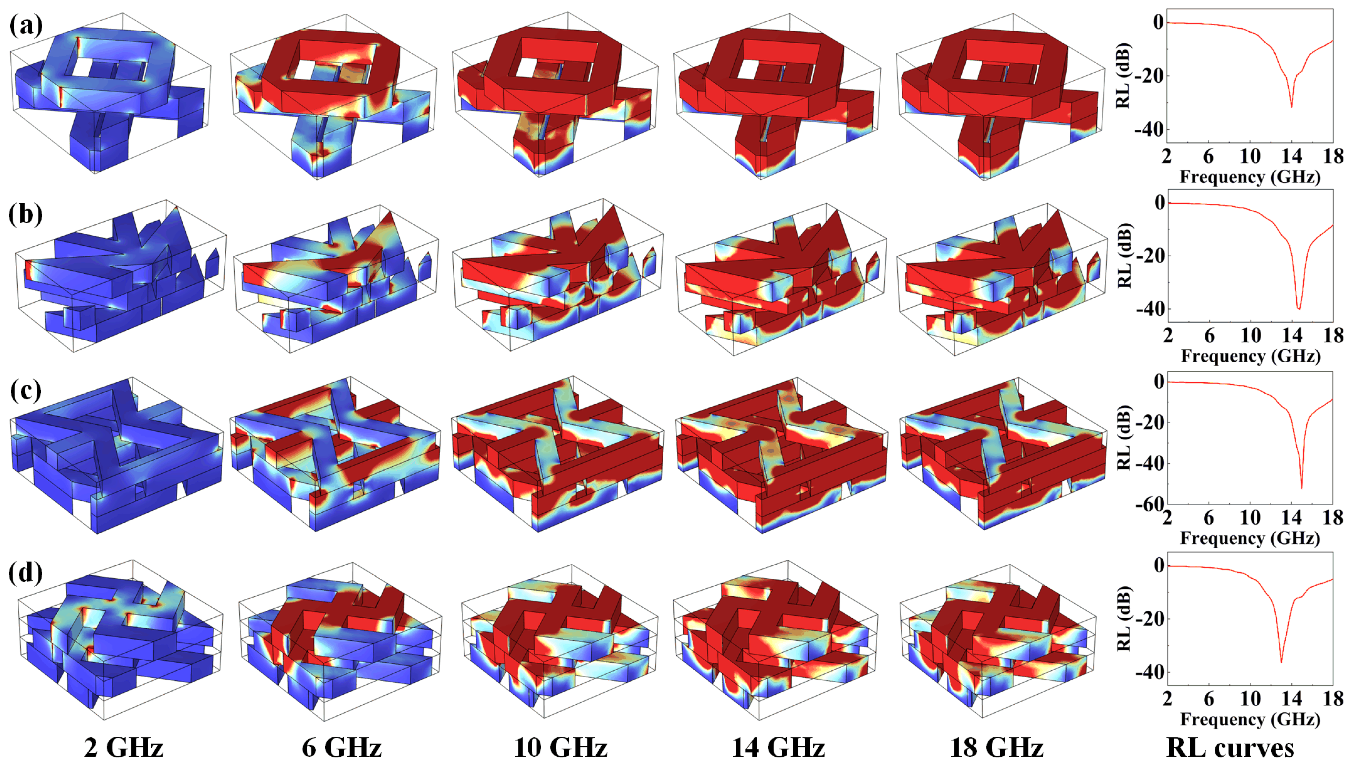
2.2. Simulation Process
3. Results and Discussion
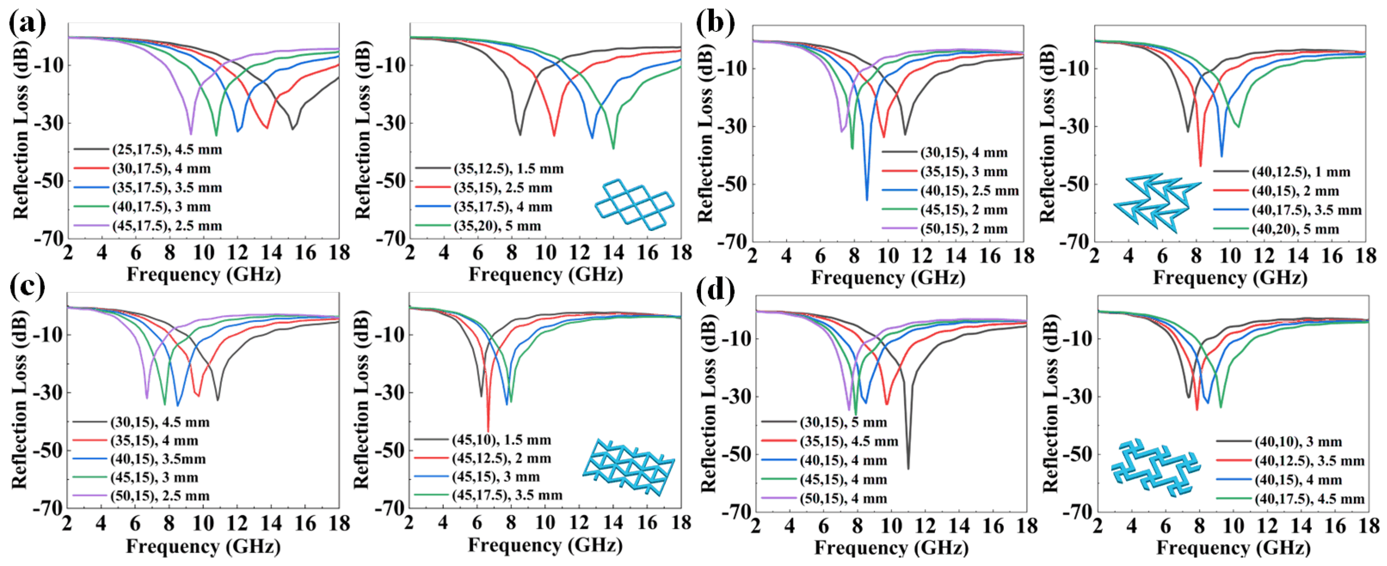
3.1. The Influence of Dielectric Constant on Absorption Performances
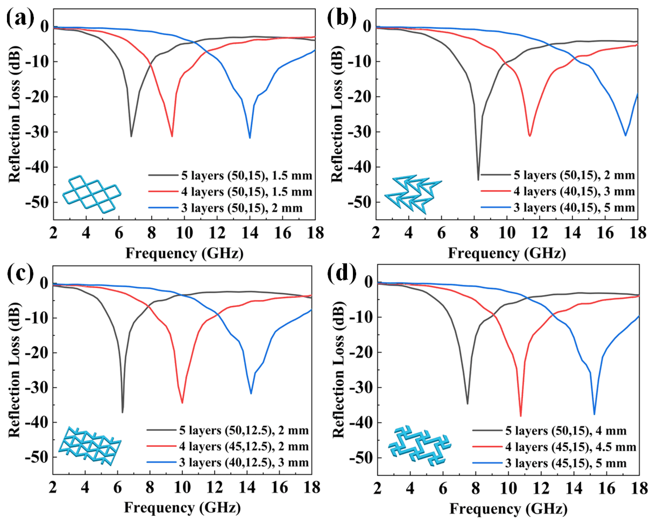
3.2. The Influence of Layer Number on Absorption Performance
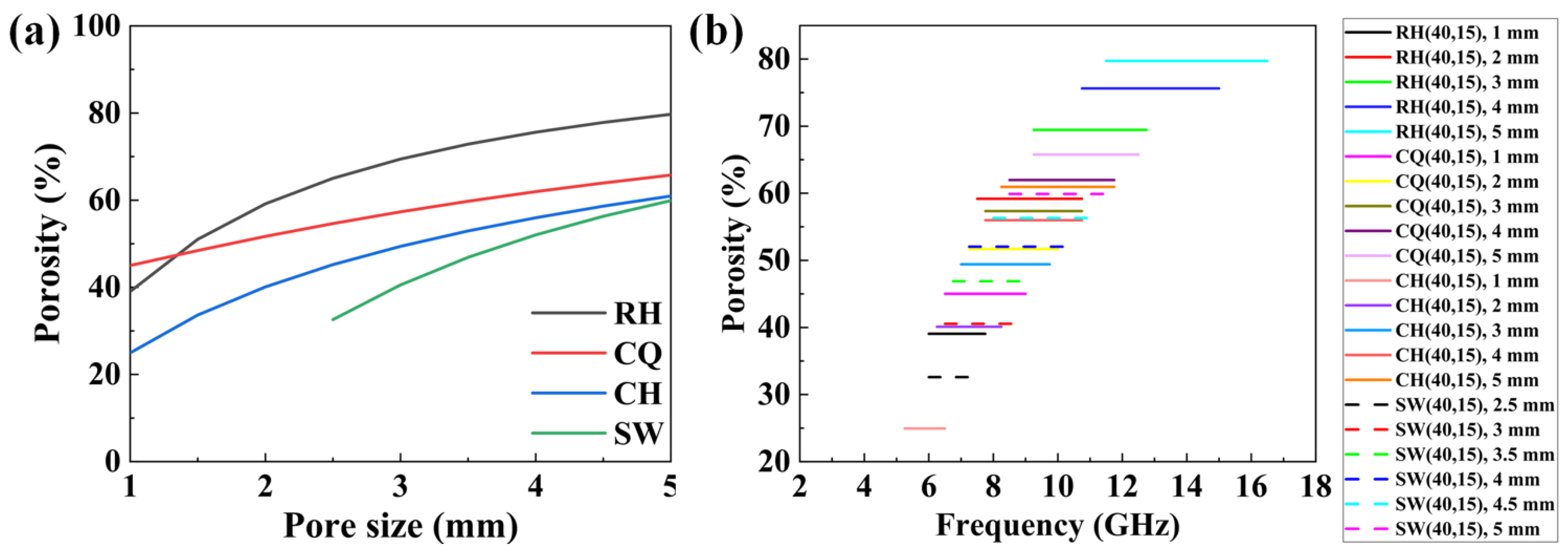
3.3. The Influence of Pore Size on Absorption Performance
3.4. The Influence of Porosity on Absorption Performance
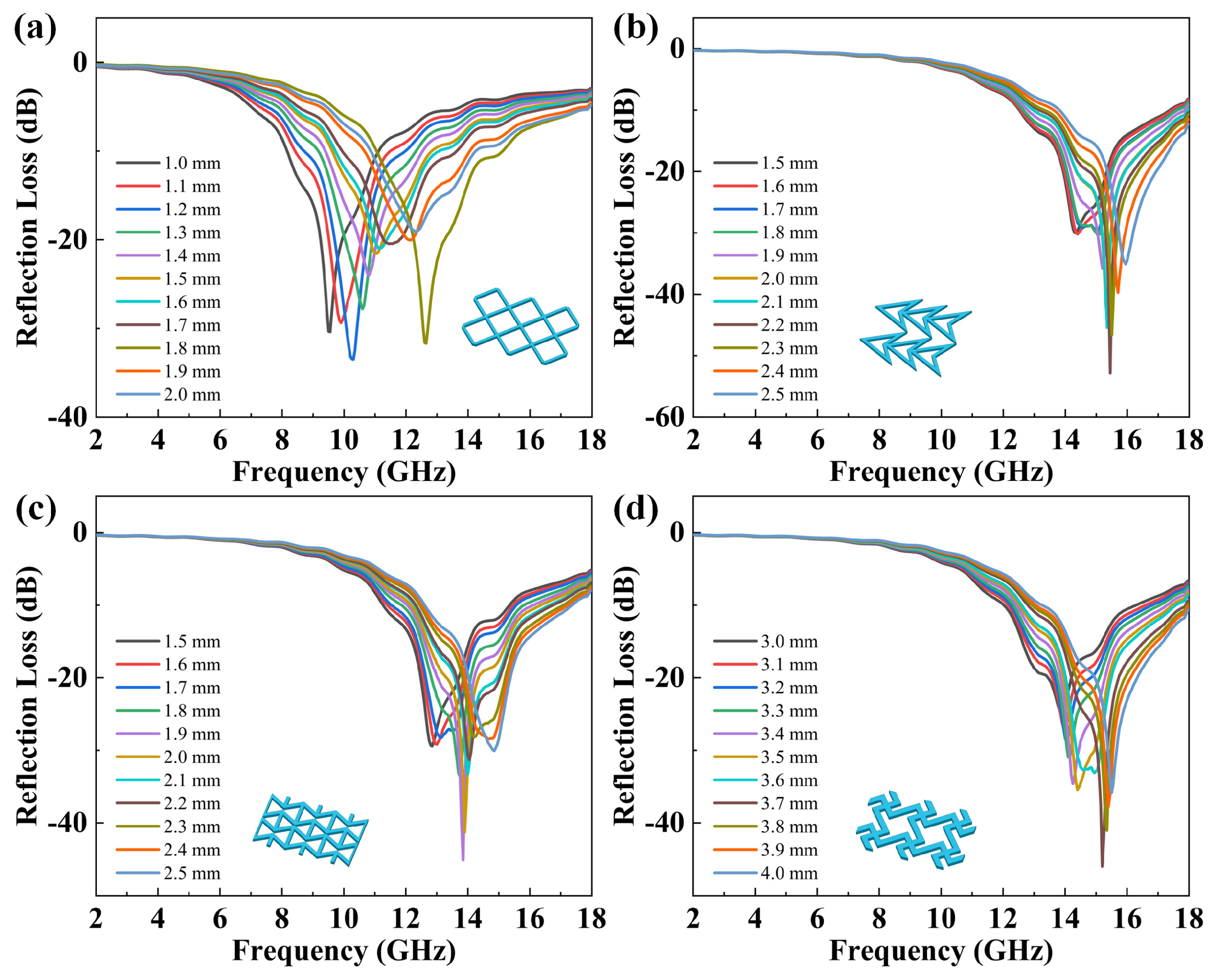
3.5. Design of Practical Auxetic MAMs
4. Conclusions
Supplementary Materials
Author Contributions
Funding
Institutional Review Board Statement
Informed Consent Statement
Data Availability Statement
Acknowledgments
Conflicts of Interest
Abbreviations
| MAM | Microwave-absorbing material |
| HFSS | High-Frequency Structure Simulator |
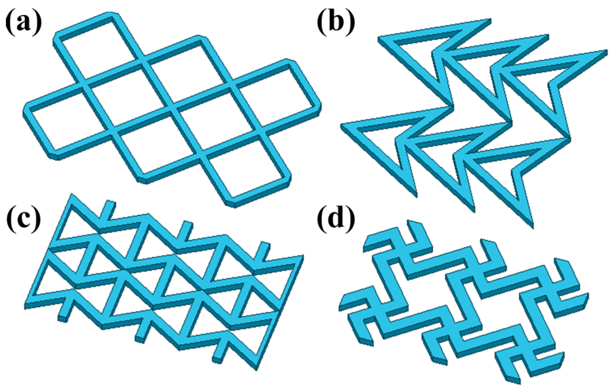
| RH | Rhombus |
| CQ | Concave quadrilateral |
| CH | Concave hexagonal |
| SW | Swastika shape |
References
- Hu, R.C.; Li, L.; Xu, X.W.; Pan, D.S.; Dong, J.F.; Zhen, C.; Gu, M.D.; Wang, H. Dimensional design of Fe0.9Co0.1 nano-alloys with enhanced low-frequency microwave absorption. Chem. Eng. J. 2024, 12, 148864. [Google Scholar] [CrossRef]
- Kong, X.K.; Wu, P.K.; Tian, S.Y.; Chen, T.; Zhao, S.; Liu, Q.C.; Ju, Z.C. All-in-one: Multi-parameter engineering on γ-Fe2O3 for ultra-broadband microwave absorption. Chem. Eng. J. 2024, 485, 150144. [Google Scholar] [CrossRef]
- Li, N.; Shi, J.F.; Zhang, F.; Jia, L.C.; Wang, Y.Y.; Yan, D.X.; Li, Z.M. Peelable Microwave Absorption Coating with Reusable and Anticorrosion Merits. ACS Appl. Mater. Interfaces 2024, 16, 6462–6473. [Google Scholar] [CrossRef]
- Zhang, X.; Tian, X.L.; Wu, N.; Zhao, S.Y.; Qin, Y.T.; Pan, F.; Yue, S.Y.; Ma, X.Y.; Qiao, J.; Xu, W.; et al. Metal-organic frameworks with fine-tuned interlayer spacing for microwave absorption. Sci. Adv. 2024, 10, 11. [Google Scholar] [CrossRef] [PubMed]
- Yuan, W.J.; Liu, H.T.; Wang, X.H.; Huang, L.; Yin, F.X.; Yuan, Y. Conductive MXene/melamine sponge combined with 3D printing resin base prepared as an electromagnetic interferences shielding switch. Compos. Part A Appl. Sci. Manuf. 2021, 143, 106238. [Google Scholar] [CrossRef]
- Liu, G.D.; Yu, R.R.; Liu, D.; Xia, Y.H.; Pei, X.Y.; Wang, W.; Min, C.Y.; Liu, S.K.; Shao, R.Q.; Xu, Z.W. 3D-printed TiO2-Ti3C2Tx heterojunction/rGO/PDMS composites with gradient pore size for electromagnetic interference shielding and thermal management. Compos. Part A Appl. Sci. Manuf. 2022, 160, 107058. [Google Scholar] [CrossRef]
- Li, D.M.; Pan, W.H.; Wang, T.; Wang, X.; Gong, R.Z. 3D printed lightweight metastructure with microwave absorption and mechanical resistance. Mater. Des. 2023, 225, 111506. [Google Scholar] [CrossRef]
- Li, J.X.; Chen, S.Y.; Fan, R.X.; Gong, X.; Zhao, H.S.; Yan, L.P.; Zhou, Y.P. Structural engineering on carbon materials for microwave absorption: From micro to macro to meta. Carbon 2024, 224, 119058. [Google Scholar] [CrossRef]
- Gong, P.; Hao, L.; Li, Y.; Li, Z.; Xiong, W. 3D-printed carbon fiber/polyamide-based flexible honeycomb structural absorber for multifunctional broadband microwave absorption. Carbon 2021, 185, 272–281. [Google Scholar] [CrossRef]
- Xing, R.Z.; Xu, G.X.; Qu, N.; Zhou, R.; Yang, J.Y.; Kong, J. 3D printing of liquid-metal-in-ceramic metamaterials for high-efficient microwave absorption. Adv. Funct. Mater. 2023, 34, 2307499. [Google Scholar] [CrossRef]
- Choi, J.H.; Jang, M.S.; Jang, W.H.; Kim, C.G. Investigation on microwave absorption characteristics of conductive-coated honeycomb absorber. Compos. Struct. 2020, 242, 112129. [Google Scholar] [CrossRef]
- Yan, H.; Fu, B.; Xuan, S.Y.; Qin, T.F.; Yao, X.F. Electromagnetic response of grading honeycomb composites for broadband microwave absorption. Compos. Struct. 2023, 321, 117280. [Google Scholar] [CrossRef]
- Li, W.C.; Xu, L.Y.; Zhang, X.; Gong, Y.; Ying, Y.; Yu, J.; Zheng, J.W.; Qiao, L.; Che, S. Investigating the effect of honeycomb structure composite on microwave absorption properties. Compos. Commun. 2020, 19, 182–188. [Google Scholar] [CrossRef]
- Luo, H.; Chen, F.; Wang, X.; Dai, W.Y.; Xiong, Y.; Yang, J.J.; Gong, R.Z. A novel two-layer honeycomb sandwich structure absorber with high-performance microwave absorption. Compos. Part A Appl. Sci. Manuf. 2019, 119, 1–7. [Google Scholar] [CrossRef]
- Pang, H.F.; Duan, Y.P.; Dai, X.H.; Huang, L.X.; Yang, X.; Zhang, T.; Liu, X.J. The electromagnetic response of composition-regulated honeycomb structural materials used for broadband microwave absorption. J. Mater. Sci. Technol. 2021, 88, 203–214. [Google Scholar] [CrossRef]
- Lakes, R.S. Negative-poisson’s-ratio materials: Auxetic solids. Annu. Rev. Mater. Res. 2017, 47, 63–81. [Google Scholar] [CrossRef]
- Zheng, Z.R.; Li, J.W.; Wei, K.L.; Tang, N.; Li, M.H.; Hu, J. Bioinspired integrated auxetic elastomers constructed by a dual dynamic interfacial healing strategy. Adv. Mater. 2023, 35, 2304631. [Google Scholar] [CrossRef]
- Xu, Y.C.; Huang, Y.Z.; Yan, H.; Gu, Z.D.; Zhao, T.Y.; Zhang, R.; Pan, B.; Dong, L.T.; Liu, M.J.; Jiang, L. Sunflower-pith-inspired anisotropic auxetic mechanics from dual-gradient cellular structures. Matter 2023, 6, 1569–1584. [Google Scholar] [CrossRef]
- Yang, H.; Ma, L. Design and characterization of axisymmetric auxetic metamaterials. Compos. Struct. 2020, 249, 112560. [Google Scholar] [CrossRef]
- Papadopoulou, A.; Laucks, J.; Tibbits, S. Auxetic materials in design and architecture. Nat. Rev. Mater. 2017, 2, 17078. [Google Scholar] [CrossRef]
- Hou, R.S.; Dong, P.; Hu, J.Y.; Gong, Z.; Sadeghzade, S.; Cao, J.R.; Yuan, H.Y. An optimized lozenge-chiral auxetic metamaterial with tunable auxeticity and stiffness. Mater. Des. 2024, 237, 112530. [Google Scholar] [CrossRef]
- Li, T.T.; Li, Y.N. Mechanical behaviors of three-dimensional chiral mechanical metamaterials. Compos. Part B Eng. 2024, 270, 111141. [Google Scholar] [CrossRef]
- Zhang, X.Y.; Ren, X.; Zhang, Y.; Xie, Y.M. A novel auxetic metamaterial with enhanced mechanical properties and tunable auxeticity. Thin–Walled Struct. 2022, 174, 109162. [Google Scholar] [CrossRef]
- Li, S.Y.; Fang, H.B.; Sadeghi, S.; Bhovad, P.; Wang, K.W. Architected origami materials: How folding creates sophisticated mechanical properties. Adv. Mater. 2019, 31, 1805282. [Google Scholar] [CrossRef]
- Li, R.X.; Chen, H.R.; Choi, J.H. Auxetic two-dimensional nanostructures from DNA. Angew. Chem. Int. Ed. 2021, 60, 7165–7173. [Google Scholar] [CrossRef]
- Lin, Z.W.; Novelino, L.S.; Wei, H.M.; Alderete, N.A.; Paulino, G.H.; Espinosa, H.D.; Krishnaswamy, S. Folding at the Microscale: Enabling multifunctional 3D origami-architected metamaterials. Small 2020, 16, 2002229. [Google Scholar] [CrossRef]
- Wang, H.R.; Zhao, D.Y.; Jin, Y.F.; Wang, M.J.; Mukhopadhyay, T.; You, Z. Modulation of multi-directional auxeticity in hybrid origami metamaterials. Appl. Mater. Today 2020, 20, 100715. [Google Scholar] [CrossRef]
- Dagdelen, J.; Montoya, J.; Jong, M.; Persson, K. Computational prediction of new auxetic materials. Nat. Commun. 2017, 8, 323. [Google Scholar] [CrossRef]
- Silva, B.; Govan, J.; Zagal, J.C.; Grossi, B.; Roldan, A.; Nunez, A.S.; Acuña, D.; Palza, H. A biomimetic smart kirigami soft metamaterial with multimodal remote locomotion mechanisms. Mater. Des. 2023, 233, 112262. [Google Scholar] [CrossRef]
- Zhang, J.J.; Lu, G.X.; You, Z. Large deformation and energy absorption of additively manufactured auxetic materials and structures: A review. Compos. Part B Eng. 2020, 201, 108340. [Google Scholar] [CrossRef]
- Hassani, F.; Javanbakht, Z.; Malek, S. Large deformation behavior and energy absorption of rotating square auxetics. Compos. Part B Eng. 2024, 283, 111596. [Google Scholar] [CrossRef]
- Alderson, A.; Alderson, K.L. Auxetic materials. Proc. Inst. Mech. Eng. Part G J. Aerosp. Eng. 2007, 221, 565–575. [Google Scholar] [CrossRef]
- Li, X.; Peng, W.T.; Wu, W.W.; Xiong, J.; Lu, Y. Auxetic mechanical metamaterials: From soft to stiff. Int. J. Extrem. Manuf. 2023, 5, 042003. [Google Scholar] [CrossRef]
- Razbin, M.; Bagherzadeh, R.; Asadnia, M.; Wu, S.Y. Recent advances in wearable electromechanical sensors based on auxetic textiles. Adv. Funct. Mater. 2024, 34, 2409242. [Google Scholar] [CrossRef]
- Jiang, Y.Z.; Plog, J.; Yarin, A.L.; Pan, Y.Y. Direct ink writing of surface-modified flax elastomer composites. Compos. Part B Eng. 2020, 194, 108061. [Google Scholar] [CrossRef]
- Friedrich, L.; Begley, M. Printing direction dependent microstructures in direct ink writing. Addit. Manuf. 2020, 34, 101192. [Google Scholar] [CrossRef]
- Han, Y.F.; Lu, W.F. Structural design of wearable electronics suitable for highly-stretched joint areas. Smart Mater. Struct. 2018, 27, 105042. [Google Scholar] [CrossRef]
- Zhang, N.; Han, M.Y.; Wang, G.H.; Zhao, Y.; Gu, W.H.; Zhou, M.; Chen, J.B.; Ji, G.B. Achieving broad absorption bandwidth of the Co/carbon absorbers through the high-frequency structure simulator electromagnetic simulation. J. Alloys Compd. 2021, 883, 160918. [Google Scholar] [CrossRef]
- Sun, H.D.; Zhang, Y.; Wu, Y.; Zhao, Y.; Zhou, M.; Liu, L.; Tang, S.L.; Ji, G.B. Broadband absorption of macro pyramid structure based flame retardant absorbers. J. Mater. Sci. Technol. 2022, 128, 228–238. [Google Scholar] [CrossRef]
- Sun, H.D.; Zhang, Y.; Wu, Y.; Li, C.; Wei, G.K.; Wang, J.W.; Liu, L.; Tang, S.L.; Ji, G.B. Broadband and high-efficiency microwave absorbers based on pyramid structure. ACS Appl. Mater. Interfaces 2022, 14, 52182–52192. [Google Scholar] [CrossRef]
- Quan, B.; Shi, W.H.; Ong, S.J.H.; Lu, X.C.; Wang, P.L.Y.; Ji, G.B.; Guo, Y.F.; Zheng, L.R.; Xu, Z.C.J. Defect engineering in two common types of dielectric materials for electromagnetic absorption applications. Adv. Funct. Mater. 2019, 29, 1901236. [Google Scholar] [CrossRef]
- You, Z.X.; Liu, S.Q.; Kuang, B.Y.; Shao, Z.Q.; Wang, C.Z.; Jin, H.B.; Li, J.B. Reduced graphene oxide/cyanoethyl cellulose composite: An example of dielectric tailoring design for efficient microwave absorption materials. Compos. Sci. Technol. 2024, 248, 110441. [Google Scholar] [CrossRef]
- Zhao, H.Q.; Seow, J.Z.Y.; Cheng, Y.; Xu, Z.C.J.; Ji, G.B. Green synthesis of hierarchically porous carbons with tunable dielectric response for microwave absorption. Ceram. Int. 2020, 46, 15447–15455. [Google Scholar] [CrossRef]
- Chen, C.; Pan, L.M.; Jiang, S.C.; Yin, S.; Li, X.Y.; Zhang, J.X.; Feng, Y.B.; Yang, J. Electrical conductivity, dielectric and microwave absorption properties of graphene nanosheets/magnesia composites. J. Eur. Ceram. Soc. 2018, 38, 1639–1646. [Google Scholar] [CrossRef]
- Wang, P.; Cheng, L.F.; Zhang, Y.N.; Yuan, W.Y.; Pan, H.X.; Wu, H. Electrospinning of graphite/SiC hybrid nanowires with tunable dielectric and microwave absorption characteristics. Compos. Part A Appl. Sci. Manuf. 2018, 104, 68–80. [Google Scholar] [CrossRef]
- Ronold, W.P.K. Electromagnetic and Acoustic Scattering by Simple Shapes. J. Franklin Inst. 1971, 291, 149. [Google Scholar] [CrossRef]
- Song, W.-L.; Fan, L.-Z.; Hou, Z.-L.; Zhang, K.-L.; Ma, Y.B.; Cao, M.S. A wearable microwave absorption cloth. J. Mater. Chem. C 2017, 5, 2432–2441. [Google Scholar] [CrossRef]
- Green, M.; Tian, L.; Xiang, P.; Murowchick, J.; Tan, X.Y.; Chen, X.B. Co2P nanoparticles for microwave absorption. Mater. Today Nano 2018, 1, 1–7. [Google Scholar] [CrossRef]
- Ye, X.; Xu, J.; Li, S.; Ma, X.M.; Mao, B.X.; Zhang, J.X.; Zheng, K. The microwave absorption properties variation with temperature of RF/SiO2 and improved microwave absorption by periodic structure. J. Alloys Compd. 2023, 968, 171905. [Google Scholar] [CrossRef]
- Wang, L.; Su, S.; Wang, Y. Fe3O4–Graphite composites as a microwave absorber with bimodal microwave absorption. ACS Appl. Nano Mater. 2022, 5, 17565–17575. [Google Scholar] [CrossRef]


| RLmin (GHz) | Layer Number | Structure | εr | Pore Size (mm) | Porosity (%) | EAB (GHz) |
|---|---|---|---|---|---|---|
| 8.2 | 5 | CH | (35, 12.5) | 2.5 | 45.21 | 3 |
| 8.25 | 5 | CQ | (40, 15) | 2 | 51.69 | 3 |
| 8.4 | 5 | RH | (35, 12.5) | 1.5 | 51.02 | 3.1 |
| 8.4 | 5 | CQ | (50, 20) | 3.5 | 59.77 | 3.2 |
| 8.7 | 5 | SW | (50, 20) | 5 | 59.90 | 3.25 |
| 8.75 | 5 | CQ | (50, 22.5) | 4 | 61.97 | 3 |
| 8.9 | 5 | CH | (45, 17.5) | 4.5 | 58.62 | 3.2 |
| 9 | 5 | CH | (40, 15) | 4 | 55.98 | 3.3 |
| 9 | 5 | RH | (40, 15) | 2 | 59.17 | 3.25 |
| 9.1 | 5 | CQ | (50, 22.5) | 4.5 | 63.95 | 3.2 |
| 9.25 | 5 | CH | (45,17.5) | 5 | 60.95 | 3.3 |
| 9.25 | 5 | CQ | (50, 22.5) | 5 | 65.75 | 3.2 |
| 9.3 | 4 | CH | (50, 15) | 3 | 49.40 | 3 |
| 9.75 | 4 | CH | (50, 17.5) | 3.5 | 52.94 | 3.1 |
| 9.9 | 4 | CQ | (50, 15) | 2.5 | 54.65 | 3.05 |
| 10 | 4 | SW | (50, 15) | 4.5 | 56.31 | 3.1 |
| 10.5 | 4 | RH | (40, 12.5) | 1.5 | 51.02 | 3.1 |
| 10.5 | 4 | CH | (50, 17.5) | 4 | 55.98 | 3.05 |
| 10.55 | 4 | CQ | (50, 15) | 3 | 57.34 | 3.1 |
| 10.85 | 4 | RH | (45, 15) | 2 | 59.17 | 3.05 |
| 10.95 | 4 | CH | (50, 17.5) | 5 | 60.95 | 3.35 |
| 11.2 | 4 | RH | (50, 17.5) | 2.5 | 65.03 | 3.75 |
| 11.75 | 3 | CQ | (50, 10) | 1 | 45.02 | 3 |
| 12.4 | 3 | CH | (50, 12.5) | 2.5 | 45.21 | 3 |
| 12.5 | 3 | RH | (50, 12.5) | 1.5 | 51.02 | 3.1 |
| 12.85 | 3 | SW | (50, 12.5) | 4 | 52.04 | 3.8 |
| 12.85 | 3 | SW | (45, 10) | 3.5 | 46.88 | 3.7 |
| 13.4 | 3 | CH | (50, 12.5) | 3.5 | 52.94 | 3.6 |
| 13.9 | 3 | CH | (50, 15) | 4 | 55.98 | 4.2 |
| 14 | 3 | RH | (50, 15) | 2 | 59.17 | 4.3 |
| 14.2 | 3 | SW | (50, 17.5) | 5 | 59.90 | 4.5 |
| 14.3 | 3 | CH | (50, 15) | 4.5 | 58.62 | 4.5 |
| 14.5 | 3 | CQ | (45, 12.5) | 3 | 57.34 | 4.6 |
| 14.7 | 3 | CQ | (50, 15) | 4 | 61.97 | 4.6 |
| 15 | 3 | CH | (50, 15) | 5 | 60.95 | 4.8 |
| 15.2 | 3 | CQ | (50, 15) | 4.5 | 63.95 | 4.8 |
| 15.9 | 3 | CQ | (45, 17.5) | 4.5 | 63.95 | 4.25 |
| 16 | 3 | RH | (45, 15) | 2.5 | 65.04 | 4.1 |
| 16.3 | 3 | CQ | (45, 17.5) | 5 | 65.76 | 4 |
| 16.4 | 3 | RH | (50, 17.5) | 3 | 69.44 | 4 |
| 17.2 | 3 | CQ | (40, 15) | 5 | 65.76 | 3.5 |
| 17.45 | 3 | RH | (50, 17.5) | 3.5 | 72.87 | 3 |
| 17.8 | 3 | CH | (35, 12.5) | 5 | 60.95 | 3 |
| Material | Thickness (mm) | EAB (GHz) | RLmin (dB) | Ref. |
|---|---|---|---|---|
| RGO–NW–CNT composites | 4 | 6.3 | −35 | [47] |
| Co2P | 1.1 | 2.4 | −39.3 | [48] |
| RF/SiO2 aerogel | 1.95 | 2.8 | −36.42 | [49] |
| Fe3O4–graphite composites | 4 | 3.3 | −40.6 | [50] |
| CQ (40, 15), 2.5 mm | 3 | 3 | −55.52 | This work |
| SW (30, 15), 5 mm | 3 | 4.5 | −54.98 | This work |
Disclaimer/Publisher’s Note: The statements, opinions and data contained in all publications are solely those of the individual author(s) and contributor(s) and not of MDPI and/or the editor(s). MDPI and/or the editor(s) disclaim responsibility for any injury to people or property resulting from any ideas, methods, instructions or products referred to in the content. |
© 2025 by the authors. Licensee MDPI, Basel, Switzerland. This article is an open access article distributed under the terms and conditions of the Creative Commons Attribution (CC BY) license (https://creativecommons.org/licenses/by/4.0/).
Share and Cite
Wang, Y.; Cai, Z.; Liu, F.; Wang, X.; Li, D.; Ma, Y.; Tong, Z.; Wang, M.; Suhr, J.; Xiao, L.; et al. Research on the Geometry Control and Microwave Absorption Performance of Auxetic Materials. Coatings 2025, 15, 689. https://doi.org/10.3390/coatings15060689
Wang Y, Cai Z, Liu F, Wang X, Li D, Ma Y, Tong Z, Wang M, Suhr J, Xiao L, et al. Research on the Geometry Control and Microwave Absorption Performance of Auxetic Materials. Coatings. 2025; 15(6):689. https://doi.org/10.3390/coatings15060689
Chicago/Turabian StyleWang, Yifei, Zhuo Cai, Fuqiang Liu, Xinyu Wang, Dandan Li, Yifei Ma, Zhaomin Tong, Mei Wang, Jonghwan Suhr, Liantuan Xiao, and et al. 2025. "Research on the Geometry Control and Microwave Absorption Performance of Auxetic Materials" Coatings 15, no. 6: 689. https://doi.org/10.3390/coatings15060689
APA StyleWang, Y., Cai, Z., Liu, F., Wang, X., Li, D., Ma, Y., Tong, Z., Wang, M., Suhr, J., Xiao, L., Jia, S., & Chen, X. (2025). Research on the Geometry Control and Microwave Absorption Performance of Auxetic Materials. Coatings, 15(6), 689. https://doi.org/10.3390/coatings15060689