Article

Erosive Wear of Stainless Steel-Based Hardfacings with Ex-Situ and In-Situ Synthesized TiC

Department of Mechanical and Industrial Engineering, School of Engineering, Tallinn University of Technology, 19086 Tallinn, Estonia
*
Author to whom correspondence should be addressed.
Coatings 2025, 15(6), 658; https://doi.org/10.3390/coatings15060658
Submission received: 2 May 2025 / Revised: 27 May 2025 / Accepted: 27 May 2025 / Published: 29 May 2025

Abstract

The resistance to erosion of stainless steel-based plasma transferred arc (PTA)-cladded hardfacings reinforced with ex-situ-synthesized TiC is compared to those reinforced using in-situ-synthesized TiC (formed from TiO2 and graphite). The PTA cladding was performed under an optimized torch linear velocity of 0.7 m/s and cladding current of 115 A. The microstructure of the cladded overlay was analyzed using scanning electron microscopy (SEM), and the phase composition was determined using X-ray diffraction (XRD). Vickers macrohardness measurements were made at representative areas at the surface of the overlays. An erosive wear test was conducted with impact angles of 30° and 90° and impact velocities of 20, 50, and 80 m/s. The formation of TiC from TiO2 and graphite started during ball milling and ended during the cladding stage. The final TiC content in the hardfacings was below nominal, which is likely due to carbide segregation occurring during the cladding process. The highest hardness was 2.4 times that of stainless steel, which was observed in the deposit containing 60 vol.% ex-situ-synthesized TiC. Both ex-situ and in-situ TiC reinforcement improved resistance to erosion, providing up to 1.5 times better resistance under the 30° impact angle and up to 6.3 times under the 90° impact angle than that of stainless steel. However, ex-situ TiC showed a slightly larger improvement. At the 30° impact angle, the primary wear mechanism is micro-ploughing, but at the 90° impact angle it is surface fatigue. Both mechanisms appeared at both angles under 80 m/s impact velocity.

Graphical Abstract

1. Introduction

The resistance of a material to erosion is important in applications where solid particles or liquid jets impinge on a surface at high velocities, causing material loss and degradation over time. In practical applications, such as oil, mining equipment, gas pipelines, energy production, etc., selecting the appropriate material can greatly improve the resistance to erosion, thereby extending the service life of the components and reducing maintenance costs [1,2].
The incorporation of titanium carbide (TiC) into an iron (Fe)-based matrix significantly enhances its ability to withstand abrasive forces, minimizing wear and thus extending the lifespan of components made from Fe-based alloys [3]. This makes TiC-Fe cermets well suited for cutting tools, bearings, and other components that experience heavy wear [4,5]. In essence, TiC-Fe materials offer a successful combination of hardness and resistance to wear, making them indispensable in industries where durability and performance are critical [6]. The relatively good oxidation resistance of TiC-based cermets enhances their adaptability to various wear conditions at different temperatures [7]. In addition, TiC-Fe ceramic-metal materials are non-toxic compared to more conventional WC-based cermets, since both the powder and sintered forms of WC-Co have been identified as toxic and carcinogenic to humans [8]. Moreover, in terms of a cost comparison with TiC-Fe-based cermet, WC-based cermet remains expensive and faces limitations in its availability, attributed to the concentration of raw materials for its production in a few specific localities [9].
The incorporation of TiC into Fe-based materials can be achieved using ex-situ and in-situ methods [10,11]. Ex-situ synthesis involves synthesizing the TiC particles separately and then subsequently incorporating them into Fe-based materials. This allows for precise control over the composition and characteristics of the TiC before applying it to the substrate [12]. In-situ synthesis involves the formation of TiC directly within the Fe-based material during the manufacturing process. This provides benefits by preventing oxidation and external contamination at the interface between the matrix and reinforcement phases. This results in improved interface strength and wettability, resulting in a stronger bond between the TiC and the matrix [6]. Additionally, this process enhances the overall toughness and strength of the composite, even at elevated temperatures, as it ensures a uniform distribution of the thermodynamically stable reinforcement phase within the matrix phase [9]. This in-situ-synthesized TiC usually also exhibits finer particle size, leading to the enhanced mechanical properties of the cermet [13].
Multiple studies have investigated the synthesis of TiC in various metal alloy overlays, including those based on titanium, cobalt, nickel, etc. Tkachivskyi et al. have conducted research focused on the development of composite stainless steel-based coatings, including those with TiC reinforcement, using high-velocity oxygen fuel spraying [14]. In Zhao et al., pure Ti powder and Cr3C2 powder served as the primary raw materials. They achieved a successful in-situ formation of TiC-reinforced coatings on a Ti6Al4V substrate by employing plasma transferred arc welding (PTAW) [15]. Gallo et al. [16] studied Fe–TiC composite overlays, employing in-situ synthesis during PTAW and applying Ti, C, and iron alloys. The results revealed that the morphology of the TiC precipitates is influenced by the chemical composition of the Fe matrix. Yuan et al. [17] focused on using plasma transferred arc (PTA) cladding to in-situ-fabricated composite carbide coatings with composition WC-TiC/FeNi. They observed that, with an increase in Ti content from 0.1 to 0.4 wt.%, the hardness of the matrix gradually increases. Mohammadikhah et al. [18] focused on the development of composite wear-resistant layers comprising ceramic particles, specifically titanium carbides and titanium carbonitrides. These particles were synthesized in-situ on low-carbon steel using the application of flux-cored arc welding. Zhang et al. [19] directly incorporated TiC particles into a coating and synthesized TiCx in-situ using the application of a low-energy pulsed laser beam. They analyzed the coatings’ microstructure, phase composition, microhardness, and wear resistance. In Zhu et al. [20], the introduction of Ti powder facilitated the in-situ formation of fine TiC grains, in contrast to the coarse ones obtained via ex-situ methods. Our previous research focused on the in-situ synthesis of TiC from pre-laid powder mixtures of stainless steel, TiO2, and graphite [21,22]. Indeed, our latest study showed that in-situ-synthesized TiC and (Ti, Nb) C increase the hardness of the stainless steel deposit [23].
The wear characteristics of hard coatings with ex-situ- and in-situ-synthesized TiC were studied by Kotarska et al. [24], who investigated Inconel 625 superalloy powder mixtures with varying concentrations of TiC (10%, 20%, and 40% vol.) for laser-cladded metal matrix composite (MMC) coatings. They found that an increased TiC content led to reduced erosion at a 30° impingement angle, but a slight increase at 90° due to a higher content of the brittle phase.
However, due to the limited quantity of research data available, a comprehensive comparison between ex-situ- and in-situ-synthesized reinforcements is currently unfeasible. The present paper aims to ameliorate this gap by focusing on the erosive wear of 316L stainless steel-based hardfacings manufactured using PTA cladding with ex-situ- and in-situ-synthesized TiC.

2. Materials and Methods

2.1. Substrate and Hardfacing Materials

S235 steel (wt.%: 0.2 C, 1.40 Mn, 0.55 Cu, 0.035 S, 0.012 Ni 0.0035 P. bal. Fe), commonly used for structural applications in construction and engineering due to its good combination of strength and weldability, was chosen as the substrate material for all the specimens. Bars with the dimensions of 70 mm × 25 mm × 10 mm (with a 70 mm × 19 mm × 2 mm groove for the feedstock powder), analogous to the ones described in [22], were used for the deposition of the TiC-reinforced hardfacings. Before processing, the bars were firstly rinsed in benzine to remove the emulsion residues from the cutting, sand blasted, and finally blown with compressed air to remove any residual abrasive.
The feedstock powders and their respective hardfacings are listed in Table 1. The initial powders used were stainless steel AISI 316L, TiO2, graphite, and TiC, with powder mesh sizes of 10–45 µm, 0.1–0.3 µm, 5.5–7.0 µm, and 2.0–3.0 µm, respectively. The quantities of C and TiC added to the powders were calculated based on the anticipated TiC content in the hardfacings. STC1 and STC3 were meant to contain approximately 40 vol.% of TiC, whereas STC2 and STC4 were meant to contain 60 vol.% of TiC. The mutual proportions of TiO2 and graphite were calculated on the basis of Equation (1) [16]:
TiO2 + 3C → TiC + 2CO

2.2. Sample Preparation

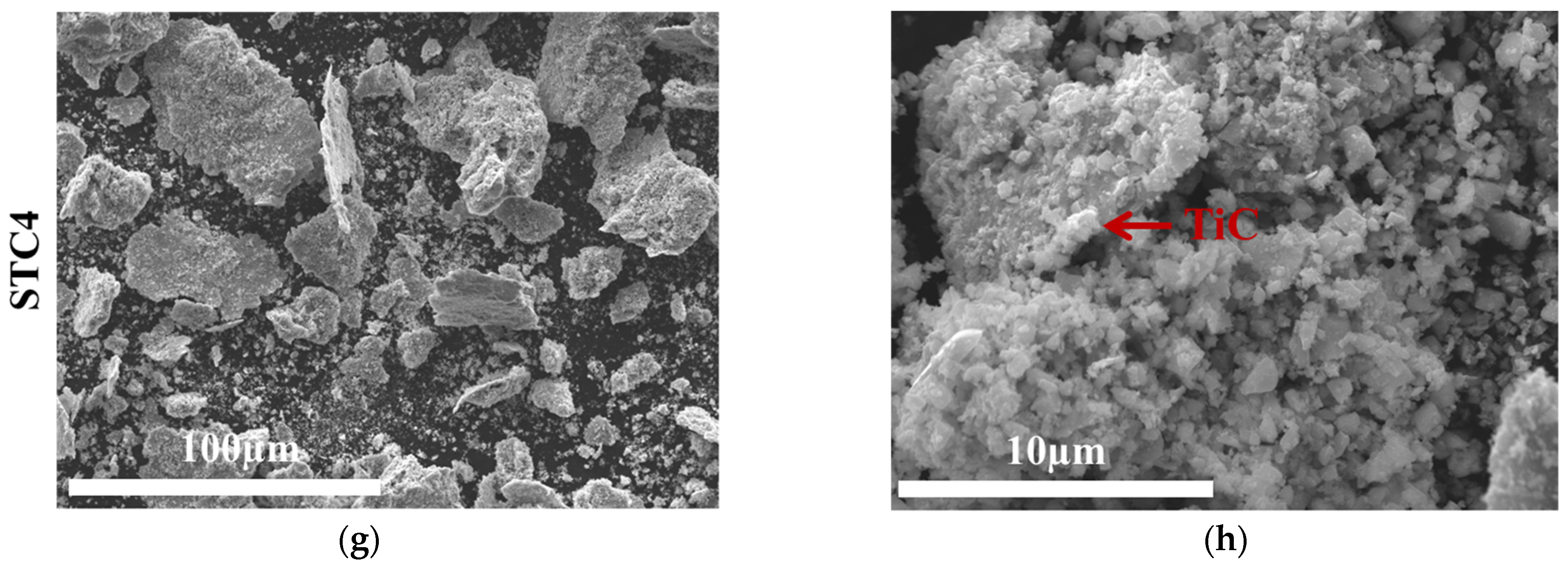
The feedstock powders (except for the reference steel one) were ball-milled for 72 h in isopropyl alcohol at a ball-to-powder ratio of 10:1 (WC-Co balls and WC-Co lining). During milling, the stainless steel particles became flattened and partially crushed into smaller flakes during the ball milling process (Figure 1). After the milling, the powders were mixed with paraffin to prepare a paste. An approximately 2 mm thick layer of this paste was pre-laid into the grooves at the substrate samples and left to dry for 24 h at room temperature. After drying, the specimens with TiC to be synthesized in-situ were preheated to 300 °C for 6 h before the cladding. The goal of this pre-heating was to minimize the thermal stress in the pre-laid powder layer during PTA cladding and, thus, avoid its peel-off.
The specimens with the ex-situ-synthesized TiC were first held in a vacuum furnace at 300 °C for 35 min to remove the paraffin and then were let to cool down until room temperature. No further preheating was applied to them so as to avoid any loss of cohesion between the TiC and the stainless steel powder.
The reference hardfacing (steel) was manufactured from the stainless steel AISI 316L only, feeding the powder to the cladding zone with a standard powder feeder. In the case of the reference specimens, flat bars with sizes of 100 mm × 25 mm × 10 mm were used as the substrate samples. Before the cladding process, these were ground using a disc cutter to remove the oxide scale. Instantly before the cladding process, the substrate bars were preheated at 300 °C for 4 h to minimize the internal stresses in the cladded hardfacings.

2.3. Cladding Process

The PTA cladding was carried out using a EuTronic Gap 3001 DC welding device by Castolin Eutectics (Dällikon, Switzerland), equipped with a plasma torch E52 (with a Ø2.4 mm tungsten electrode, grade WT20) and two standard powder feeders EP2. The pre-laid powder layers were remelted, employing preliminarily optimized parameters (linear torch velocity of 0.7 mm/s and cladding current of 115 A) both for the hardfacings with the ex-situ- and in-situ-synthesized TiC. The reference hardfacing from steel AISI 316L was cladded under a cladding current of 95 A, linear torch velocity of 0.7 mm/s, and powder feed rate of 13 g/min (0.22 g/s).
Argon (Ar) was used as the plasma gas, flowing at the rate of 0.025 dm3/s (1.5 dm3/min). To protect the cladding zone, two shield gases were employed: the first shield gas was 99.996% pure argon (Ar), and the second shield gas was a mixture of 95 vol.% argon and 5 vol.% hydrogen (H2) at a flow rate of 0.108 dm3/s (6.5 dm3/min) each.
The use of two shield gases was due to the design of the plasma torch, typically used with two powder feeders. It is technically infeasible to disconnect the powder feeders from the plasma torch or interrupt the carrier gas flow to prevent air from entering the cladding zone. Consequently, the carrier gas flowing to the plasma torch is regarded as a shield gas only.

2.4. Microstructural Studies

Cross-sections of the specimens were embedded in epoxy resin, ground with 120–2500 grit sandpaper, and polished with 6 µm–1 µm Al2O3 suspensions. After the polishing, the cross-sections were studied under the SEM Evo MA-15, Carl Zeiss (operated at an acceleration voltage of 15 kV in high-vacuum mode). The chemical composition of the hardfacings was analyzed using an energy dispersive X-ray spectroscopy (EDS) device, INCA Energy 8113, with 20 kV accelerating voltage. The phase composition of the feedstock powders and the hardfacing was assessed by the X-Ray diffraction (XRD) method using a Rigaku Smartlab device, using Cu Kα radiation (λ = 1.5406 Å, operating at 40 kV and 30 mA) over a 2θ range of 15–95°, with a step size of 0.040° and a measurement period of 1 s.

2.5. Mechanical Testing

Vickers hardness measurements were taken using the Indentec 5030 SKV hardness device, adhering to standard EN-ISO-6507 [25]. The measurements were taken at load of 5 kgf (49.05 N) with a dwell time of 10 s. The average Vickers hardness was determined by calculating the values from ten randomly selected points on the hardfacing surfaces, which were preliminarily ground flat.

2.6. Erosive Wear Testing

The erosive wear tests were conducted according to standard GOST 23.208–78 [26] using the CAK-5 erosion test device, described elsewhere [27]. For this test, samples with dimensions of 25 mm × 10 mm × 5 mm were machined from the cladded specimens. Before and after each test, they were ultrasonically cleaned in acetone and weighed using a Kern ABP 100-5DM electronic balance (produce by KERN & SOHN GmbH, in Balingen, Germany) (readability 0.1 mg) to determine the mass loss. The test conditions for the erosive wear test are provided in Table 2. The wear loss of the specimens was determined using the average weight loss from the difference between the initial and final weights after testing.

3. Results and Discussion

3.1. Phase Analysis

Figure 2 illustrates the XRD patterns of the powders after 72 h of ball milling. Ball milling appears to induce the formation of ferrite (α-Fe) in addition to austenite (γ-Fe) in the stainless steel powder. It is also seen that the TiC phase is formed in both in-situ powders already during the milling stage. In addition, the MoC phase is visible as another carbide phase. A comparative analysis reveals that the in-situ powders (STC1 and STC2) also contain TiO2 and graphite.
Both carbides (TiC and MoC) were presumably formed due to a mechanically induced self-propagating reaction [28,29] between the graphite and either the titanium dioxide or the stainless steel powder, respectively. It is interesting to note that, despite many reports of in-situ synthesis of TiC during ball milling [30,31,32,33], the specific in-situ synthesis of TiC from TiO2 and graphite or other carbon-containing media has so far been considered to not be feasible during this stage [34,35]. The exact reason for the opposite situation needs further investigation. Currently, it is suggested that the application of finer powders, in comparison with those used in the studies referred to above, could favour their intermixing [36] and thus create more favourable conditions for the reaction between TiO2 and graphite.
Despite the presence of both Cr and Mo in AISI 316L, only MoC was detected after 72 h of ball milling, while no chromium carbides were observed. This can be attributed to the more negative Gibbs free energy of formation for MoC (−35 to −50 kJ/mol C) compared to Cr-carbides (−20 to −30 kJ/mol C), making MoC thermodynamically more favourable. Additionally, Mo has higher diffusivity and a stronger carbide-forming tendency in solid-state conditions [37,38]. The available carbon is preferentially consumed by Ti and Mo, leaving insufficient carbon for chromium carbide formation.
On the grounds of the earlier publications [37,38], the probability of in-situ formation of a molybdenum-based carbide was higher. At the same time, no signs of the formation of mixed Ti-Mo-carbides were found.
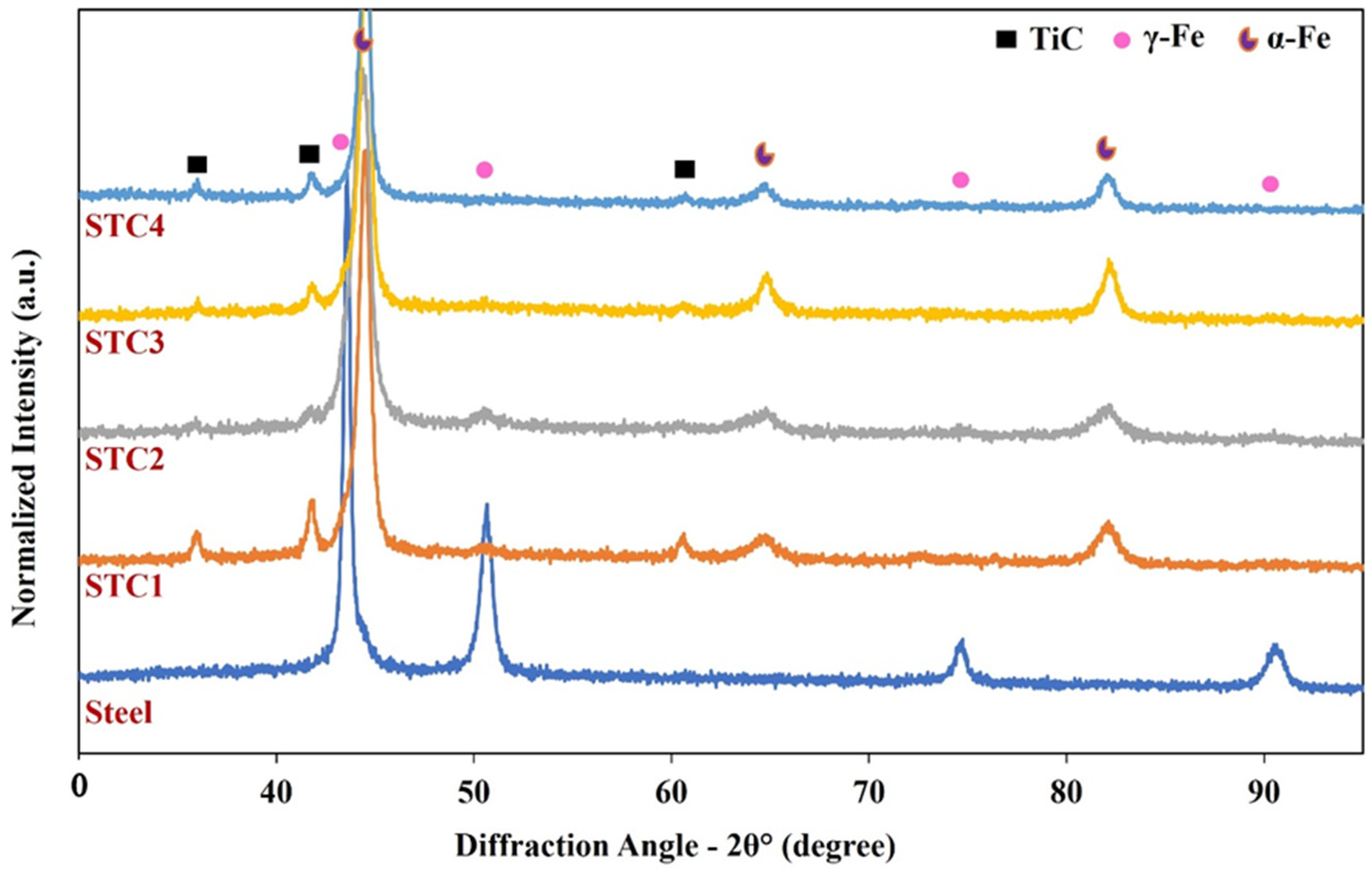
Figure 3 presents the XRD patterns of the PTA-cladded hardfacings. In all of these patterns, except for the reference hardfacing, there are clearly visible peaks corresponding to TiC and α-Fe. This indicates that the combination of stainless steel and TiO2 powders does not result in the creation of new intermetallic or carbide phases following PTA cladding, except for TiC. This observation also indicates that a predominant portion of the carbon atoms are incorporated within the TiC structure. In the steel hardfacing, γ-Fe was the only detectable phase.
The phase transformation from γ-Fe to α-Fe in the stainless steel matrix after its reinforcement with TiC has been reported multiple times [2,39,40]. According to Wang et al. [39], the in-situ-synthesized TiC grains reduce the stability of γ-Fe during cooling, thus inducing the appearance of α-Fe. According to Wu et al. [2], this happens because of tensile stresses, induced by the difference in coefficients of thermal expansion of TiC and γ-Fe. Such tensile stresses make α-Fe more thermodynamically feasible due to the lower atomic packing efficiency of its crystal lattice and, thus, lower free energy.

3.2. Microstructural Characterization

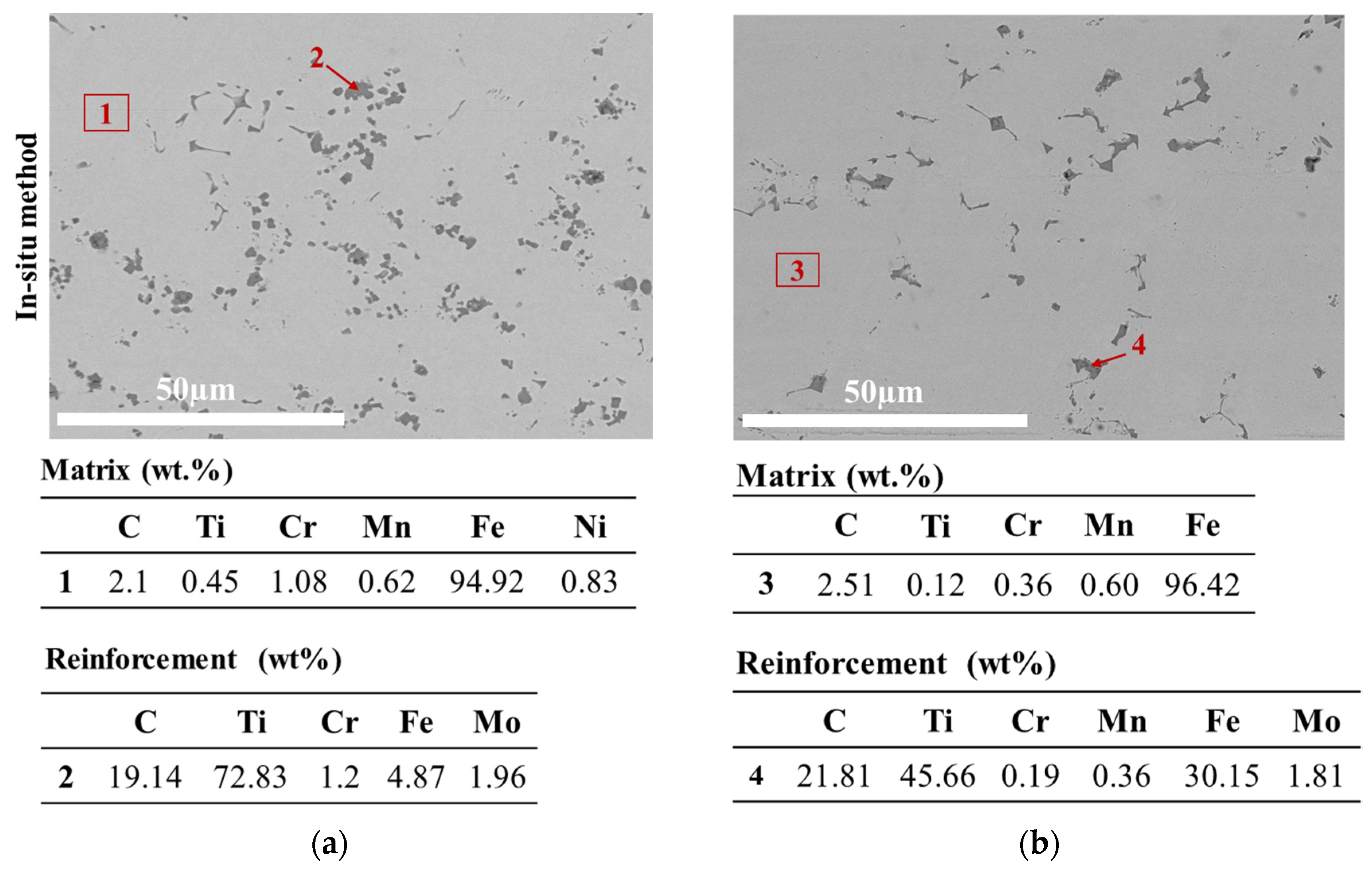
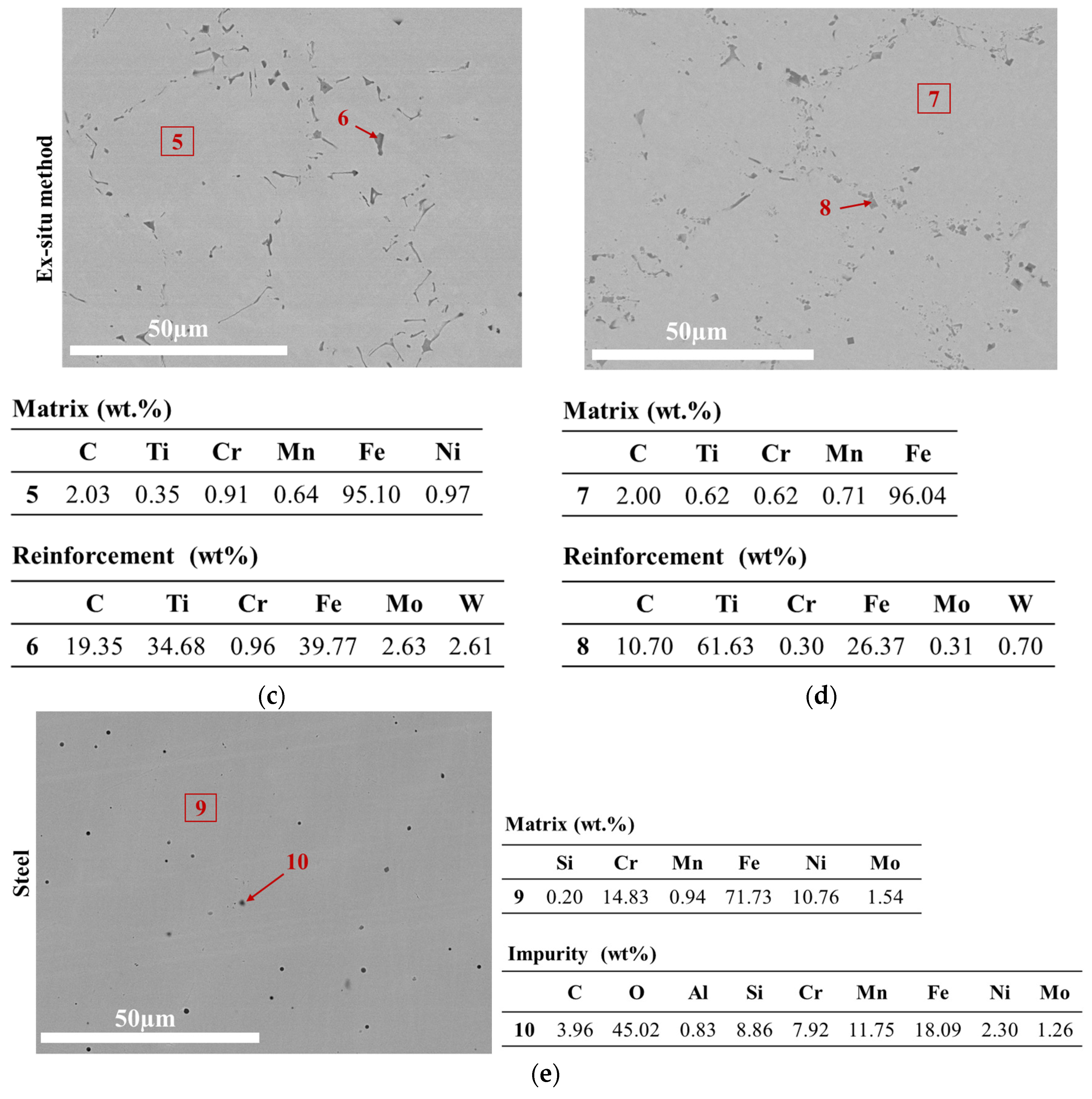
All the SEM images, except those of the steel hardfacing, display two distinct phases of different contrasts, as seen in Figure 4. The darker phase is identified as TiC, and the areas with brighter contrast are composed of the α-Fe phase. As with the in-situ-synthesized reinforcement and the ex-situ-synthesized one, it should be noted that the actual amount of TiC was remarkably lower than the nominal amount. The most probable explanation is that, due to its lower density, TiC tends to segregate in the near-surface layer of a hardfacing [3,15]. During further sample preparation (grinding) for further testing, this layer is probably removed.
Mostly, TiC was observed at the ferrite grain boundaries. The carbide phase grains in the hardfacings with the in-situ-synthesized TiC had a predominantly polygonal shape (Figure 4a,b). On the other hand, the carbide phase in the hardfacings with ex-situ-introduced TiC mostly had a platelet shape (Figure 4c,d). Ex-situ TiC powder was supposedly dissolved in the molten stainless steel during the cladding. During cooling, the melt is solidified, and reprecipitation of TiC took place. That could explain a grain shape, which is notably different from that of the initial feedstock powder.
The distribution and morphology of TiC are also affected by the PTA cladding process parameters, such as arc current, travel speed, and powder feed rate, which influence the thermal profile and cooling rate, thereby impacting the extent of TiC dissolution, segregation, and reprecipitation during solidification [41].

3.3. Hardness of the Hardfacings

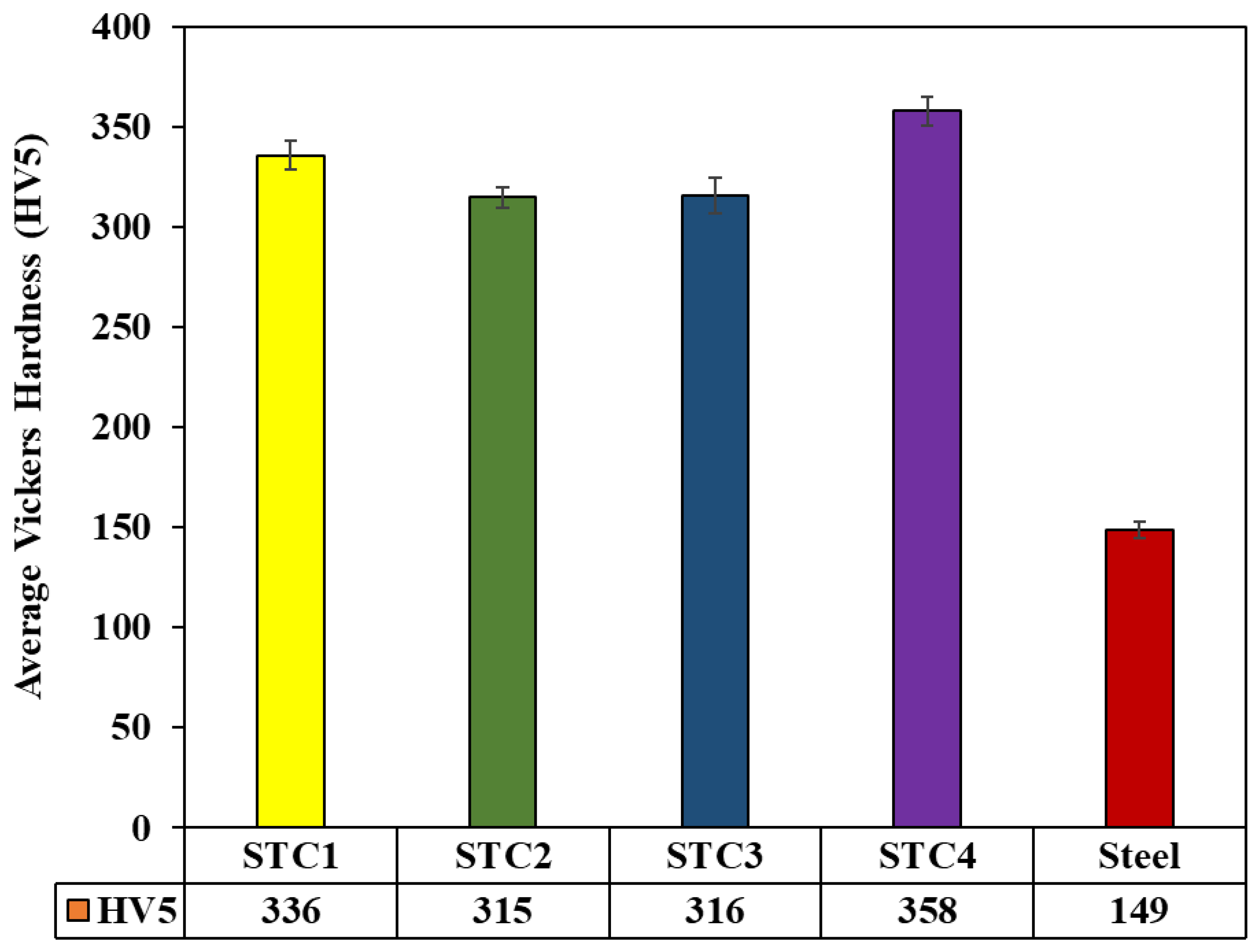
Figure 5 shows the average values of the macrohardness of the studied hardfacings. The maximum hardness recorded (358 ± 7 HV5) corresponds with the ex-situ synthesis of TiC, namely the STC4 hardfacing. The other TiC-reinforced hardfacings (STC1, STC2, and STC3) have hardnesses of 336 ± 7 HV5, 315 ± 5 HV5, and 316 ± 9 HV5, respectively. The variation in these values can be attributed to the uneven distribution of the TiC grains, as the indenter encounters a greater proportion of the harder phase in certain regions and a smaller one in others.
The average hardness generally corresponds with the TiC content in the microstructure of a hardfacing, as observed in Figure 4. It was interesting to note that the hardfacings with the ex-situ-synthesized TiC had approximately the same hardness irrespective of the initial amount of introduced TiC. This might be evidence of a reinforcement separation and loss during grinding, as mentioned earlier.

3.4. Erosive Wear

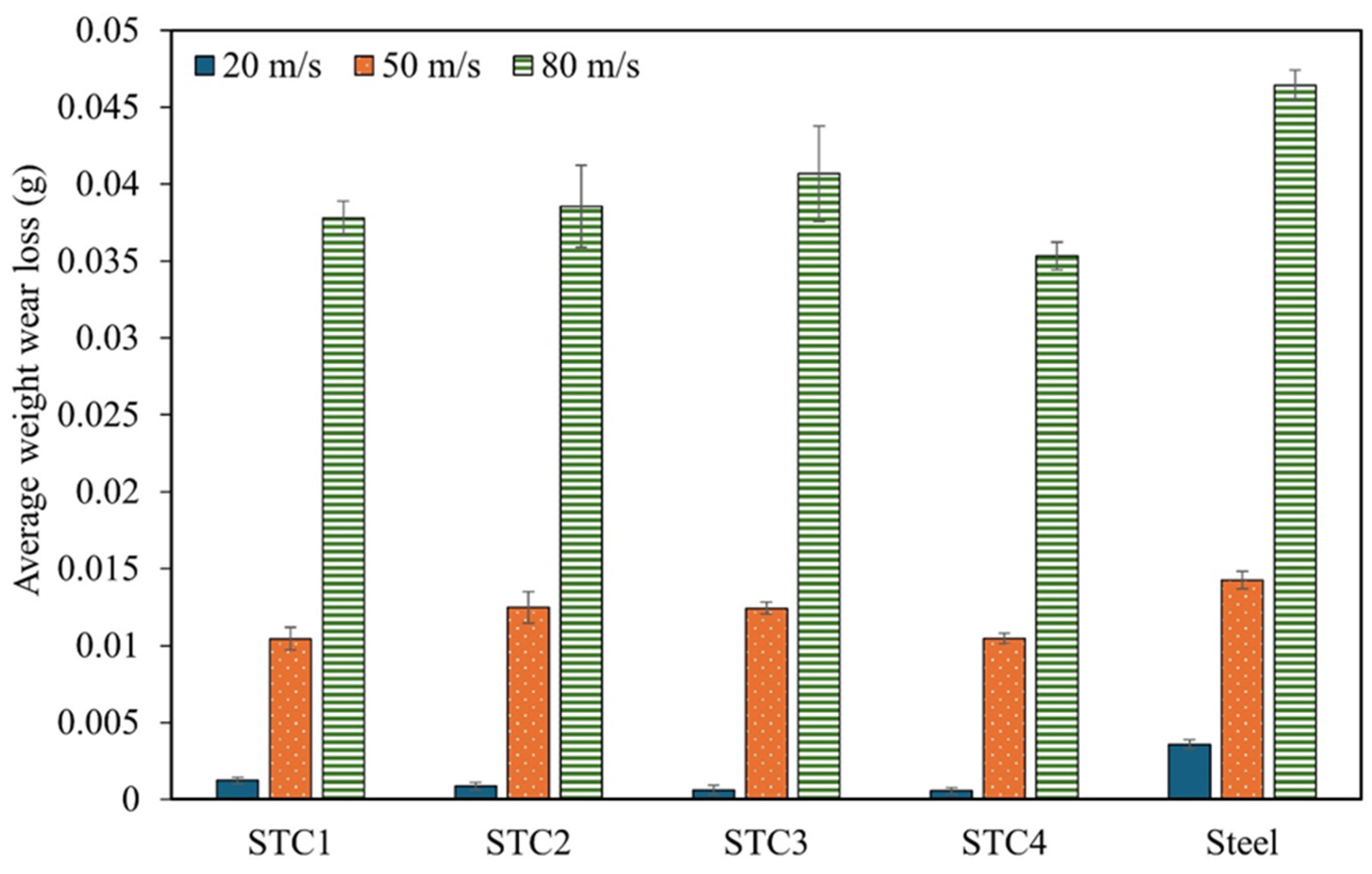
All of the hardfacings exhibited similar losses to erosion at both 30° and 90° impact angles (Figure 6 and Figure 7). Generally, the presence of TiC in the microstructure helped to enhance the resistance of the stainless steel hardfacings to erosive wear by up to 1.5 times under the 30° impact angle and by up to 6.3 times under the 90° impact angle, with the effect becoming less pronounced with an increase in the velocity of the erodent particles. No clear correlation with the previously measured hardness was found.
On average, the smallest loss was in the case of the STC4 hardfacing, nominally designed to contain 40 vol.% of ex-situ-added TiC, followed by the STC1 hardfacing, nominally designed to have 40 vol.% of in-situ-synthesized TiC (except for the lowest impact speed, 20 m/s).
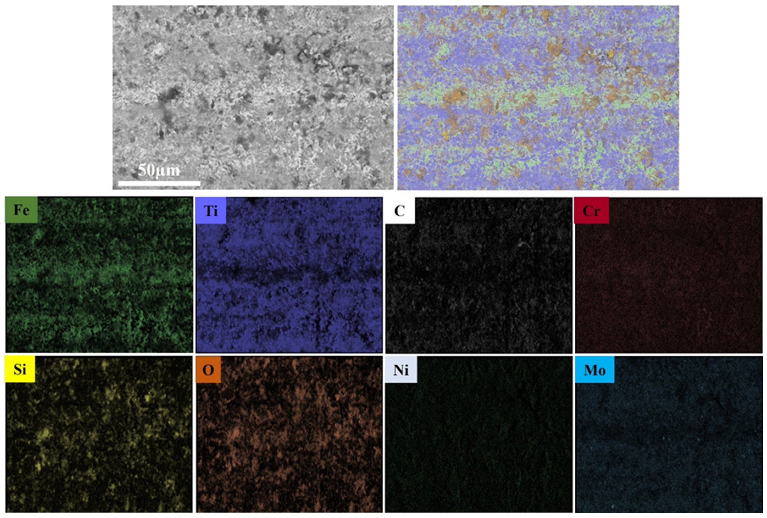
The EDS mapping of the STC2 hardfacing (nominally 60 vol.% in-situ-synthesized TiC), chosen as an example (Figure 8), illustrates the distribution of TiC, constituent of the Fe-based matrix, and the accumulation of residual quartz sand erodent at the worn surface. The formation of a mechanically mixed layer [42,43] that should impede further wear loss is observed.
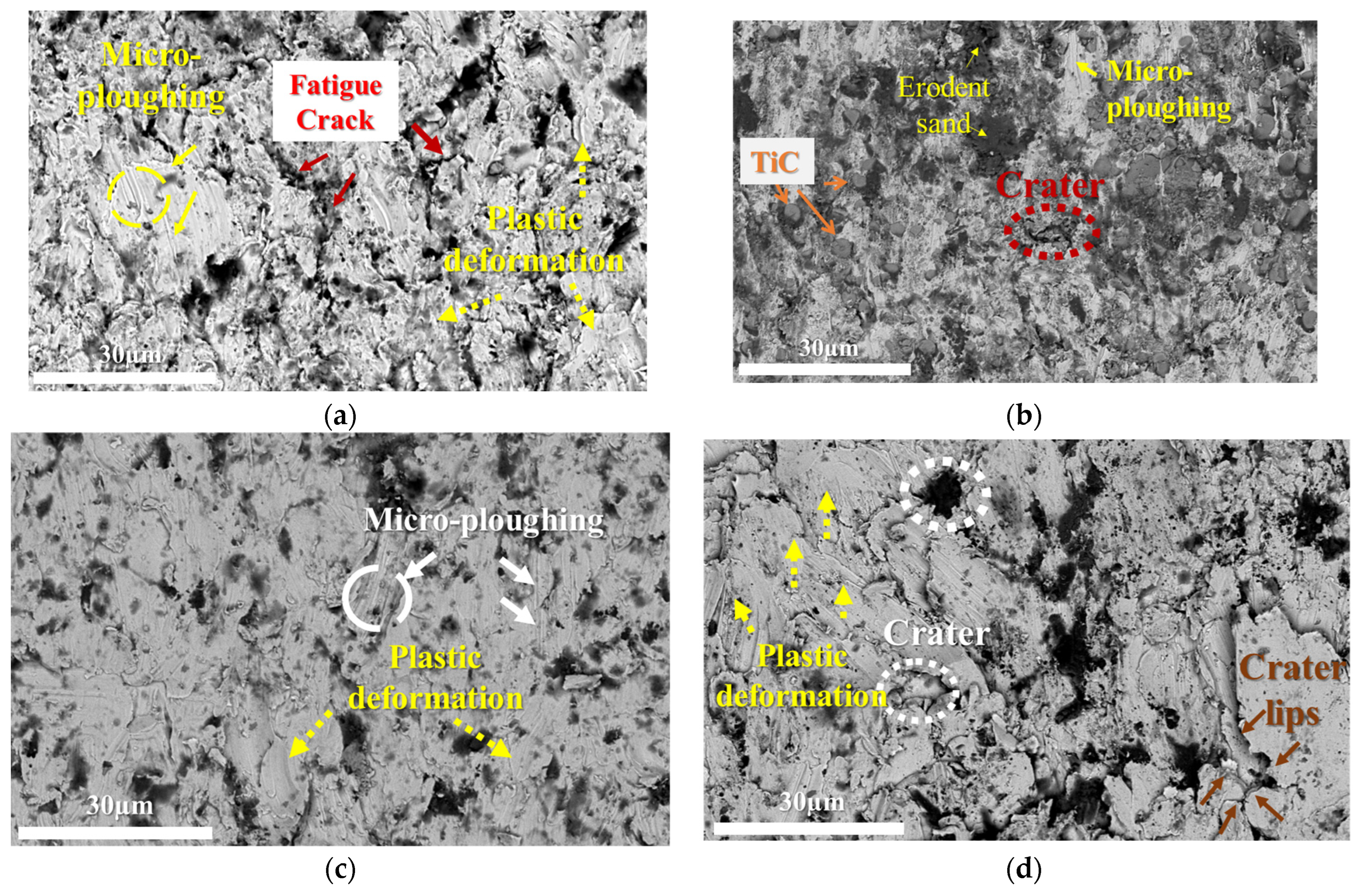
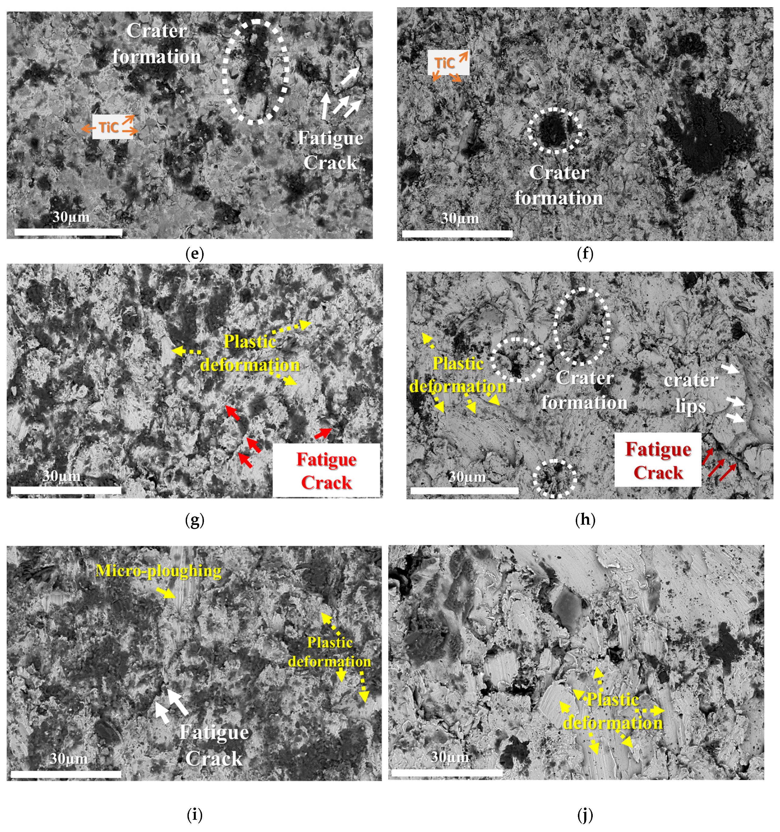
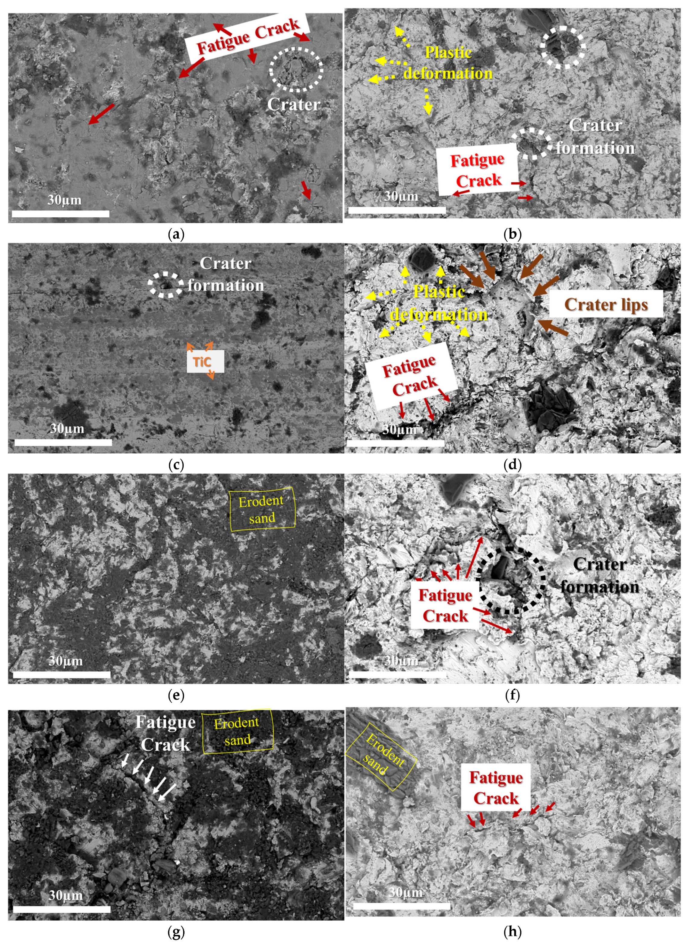
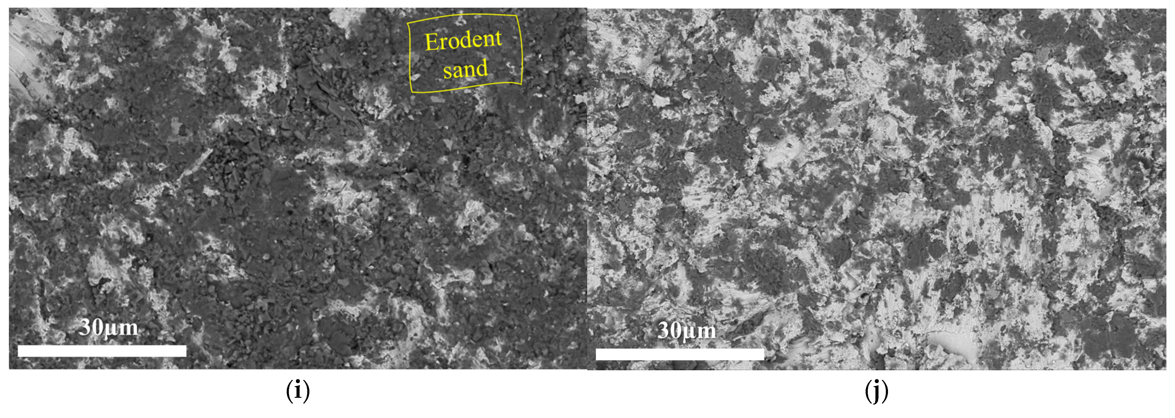
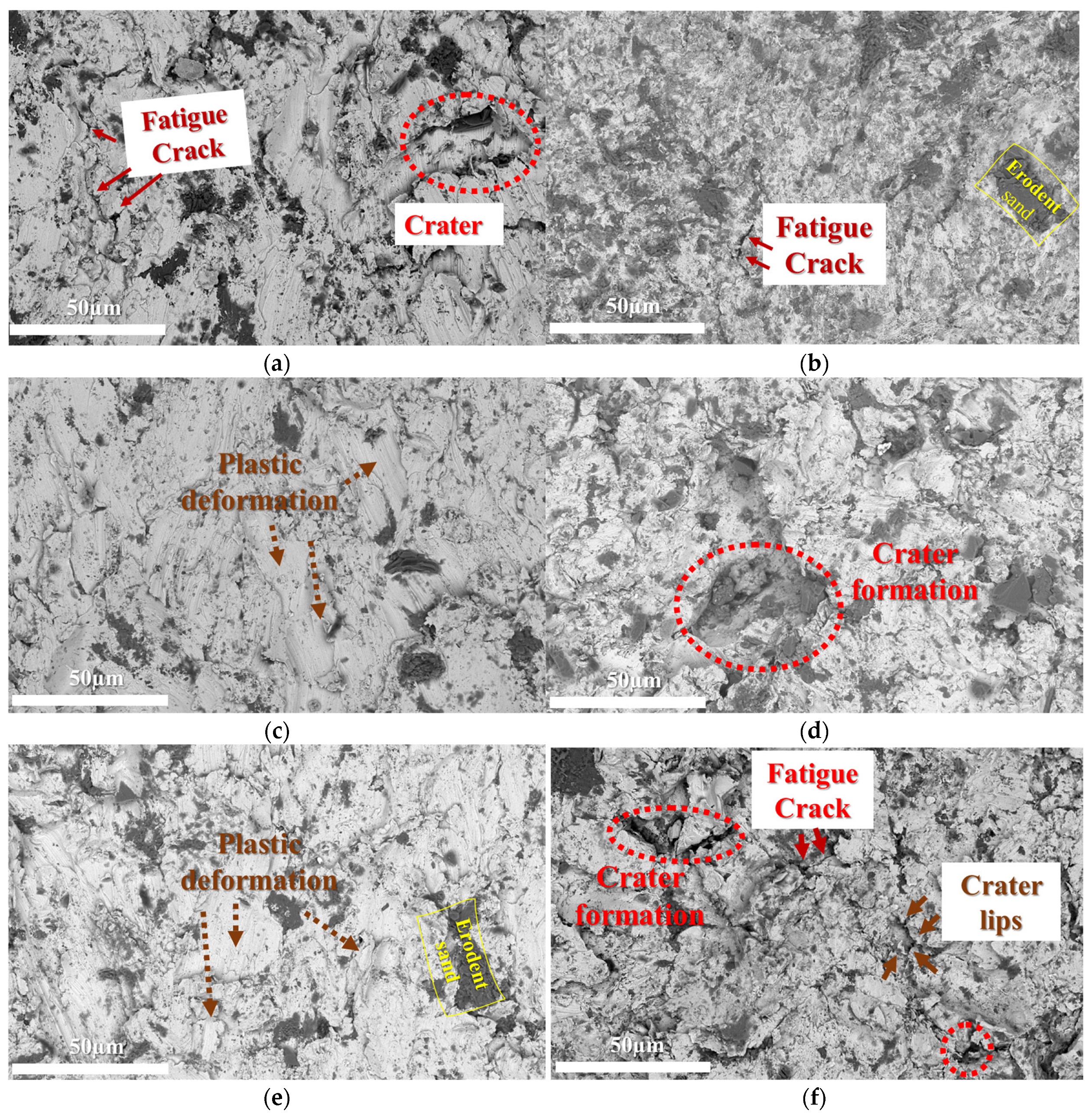
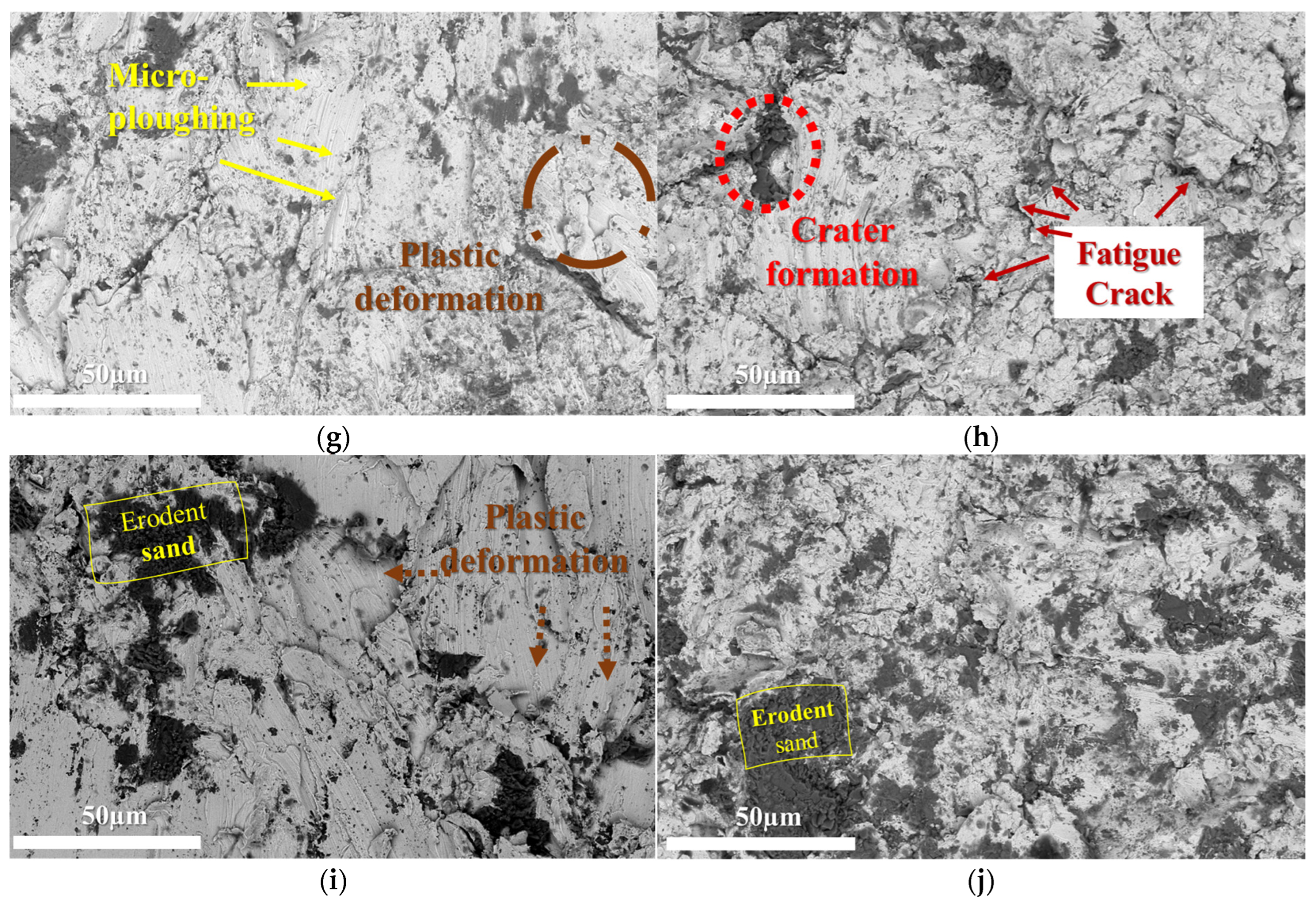
To understand the wear mechanisms, the morphology of the worn surfaces was analyzed using SEM. Figure 9, Figure 10 and Figure 11 present SEM backscattered electron images of the worn surfaces of each hardfacing. All examined surfaces showed an accumulation of erodent residuals; however, the worn surface of the steel hardfacing was covered more extensively than other hardfacings. STC1 (low C) and STC2 (high C) also show the presence of the TiC phase on the worn surfaces, particularly in areas with micro-ploughing.
At the low impact angle (30°), micro-ploughing emerged as the dominant wear mechanism for all the hardfacings examined. Apart from that, plastic deformation, and, to a lesser extent, surface fatigue, occurred under the impacting action of the eroding particles, indicating that the affected area exhibits ductile behaviour. Micro-ploughing was notably prevalent in hardfacings with lower hardness, especially STC2. In addition, STC1 and STC2 showed more pronounced plastic deformation. STC3 (low TiC) and STC4 (high TiC) generally showed greater resistance to surface damage under a low impact angle. However, they were also more brittle, as evidenced by the formation of craters and fatigue cracks.
At the high impact angle (90°), the primary wear mechanism was surface fatigue. This process involved several stages: initially, median cracks formed beneath the surface of the coating, followed by the initiation and propagation of lateral cracks parallel to the surface. These lateral cracks eventually intersected with the surface, leading to the spallation of flat fragments [44,45]. This is more pronounced at higher speeds, consistent with increased energy impacts.
Under the 90° impact angle, as seen in Figure 11, STC1 displayed substantial erodent sand embedding. At the highest impact speed, both wear mechanisms (ploughing and surface fatigue) were observed for all samples. STC2 displayed significant plastic deformation and large craters, suggesting that the material could withstand a single high-stress impact without fracturing, but experienced notable material loss under repeating impacts. STC3 displayed plastic deformation at both angles, with less severe surface damage than for STC2. STC4 displayed micro-ploughing, crater formation, and fatigue cracks at both testing angles, with the presence of micro-ploughing, craters, and fatigue cracks indicating failure under repeated or high-energy impacts.
As may be observed in Figure 6 and Figure 7, the hardfacings with ex-situ-synthesized TiC had slightly better wear resistance compared to those with the in-situ-synthesized one. Specifically, STC4 had the lowest average weight loss at both angles (30° and 90°) among all the studied hardfacings. This indicates that neither is erosion wear resistance merely determined by the amount of TiC present, nor by surface hardness, but also by the distribution and size of the carbides. As Camurri et al. [46] pointed out, wear resistance is not solely dependent on the amount of carbide phase, but is highly affected by its morphology, size, and distribution. Radziejewska [47] also emphasized that a more homogeneous distribution of reinforcing phases can improve resistance to wear. Additionally, Chen et al. [48] demonstrated that smaller well-distributed particles tend to enhance wear resistance, finding that smaller Si-rich grains, homogeneously distributed in the Al-matrix, led to a better resistance to microabrasion. The ex-situ samples, especially STC4, have more homogenous distributions and finer morphologies of TiC, which may have contributed to their enhanced wear resistance.

4. Conclusions

This study investigates the resistance to erosion of Fe-based hardfacings reinforced with ex-situ and in-situ synthesized TiC using PTA cladding. The following conclusions are drawn:
  • The formation reaction of TiC from TiO2 and graphite starts at the ball milling stage and is completed during cladding.
  • The resulting content of TiC was far below nominal in both hardfacings with the in-situ- and ex-situ-synthesized carbide, presumably due to its segregation during cladding.
  • The highest hardness (2.4 times that of the reference hardfacing) was observed for the cladded deposit, projected to contain 60 vol.% of ex-situ-synthesized TiC, while the remaining hardfacings exhibited comparative hardness values.
  • Hardfacings with both ex-situ-added and in-situ-synthesized TiC reinforcement exhibited similar resistance to erosion (up to 1.5 times under the shallow impact angle (30°) and up to 6.3 times under the normal impact angle (90°)), while hardfacings with the ex-situ introduced TiC reinforcement generally exhibited slightly lower wear.
  • The principal wear mechanisms for all the hardfacings were micro-ploughing under a shallow impact angle (30°) and surface fatigue under a normal impact angle (90°), except for the impact velocity 80 m/s, when both mechanisms occurred simultaneously under both angles.

Author Contributions

Conceptualization, S.Y. and A.S.; methodology S.Y., A.S., M.T. and M.K.; validation, S.Y. and A.S.; formal analysis, S.Y.; investigation, K.J.; resources, K.J.; writing—original draft preparation, S.Y.; writing—review and editing, A.S.; visualization, S.Y.; supervision, A.S. and K.J.; project administration, K.J.; funding acquisition, K.J. All authors have read and agreed to the published version of the manuscript.

Funding

This research was supported by the Estonian Research Council under Grant PRG1145 and the Archimedes Foundation project DAR16030.

Institutional Review Board Statement

Not applicable.

Informed Consent Statement

Not applicable.

Data Availability Statement

The original contributions presented in this study are included in the article. Further inquiries can be directed to the corresponding author.

Acknowledgments

Special thanks are extended to Mart Viljus for contributions to the scanning electron analysis and to Rainer Traksmaa for assistance with the X-ray diffraction analysis. Sincere appreciation is also extended to Maksim Antonov for providing access to laboratory facilities essential for conducting the erosive wear testing experiments.

Conflicts of Interest

The authors declare no conflicts of interest.

Abbreviations

The following abbreviations are used in this manuscript:
PTAplasma transferred arc
SEMscanning electron microscopy
XRDX-ray diffraction
EDSenergy-dispersive X-ray spectroscopy

References

  1. Kübarsepp, J.; Juhani, K. Cermets with Fe-alloy binder: A review. Int. J. Refract. Met. Hard Mater. 2020, 92, 105290. [Google Scholar] [CrossRef]
  2. Wu, C.L.; Zhang, S.; Zhang, C.H.; Zhang, J.B.; Liu, Y. Formation mechanism and phase evolution of in-situ synthesizing TiC-reinforced 316L stainless steel matrix composites by laser melting deposition. Mater. Lett. 2018, 217, 304–307. [Google Scholar] [CrossRef]
  3. Wang, Z.; Zhou, M.; Zhu, M.; Jiang, Y.; Sui, Y. Effect of precursor density on the wear resistance of in-situ TiC/Fe matrix composites based on Fe–Cr system moderator. Ceram. Int. 2023, 49, 18925–18936. [Google Scholar] [CrossRef]
  4. Razavi, M.; Yaghmaee, M.S.; Rahimipour, M.R.; Razavi-Tousi, S.S. The effect of production method on properties of Fe-TiC composite. Int. J. Miner. Process. 2010, 94, 97–100. [Google Scholar] [CrossRef]
  5. Chen, M.; Zhuang, Q.; Lin, N.; He, Y. Improvement in microstructure and mechanical properties of Ti(C,N)-Fe cermets with the carbon additions. J. Alloys Compd. 2017, 701, 408–415. [Google Scholar] [CrossRef]
  6. AlMangour, B.; Grzesiak, D.; Yang, J.M. In-situ formation of novel TiC-particle-reinforced 316L stainless steel bulk-form composites by selective laser melting. J. Alloys Compd. 2017, 706, 409–418. [Google Scholar] [CrossRef]
  7. He, S.; Fan, X.; Chang, Q.; Xiao, L. TiC-Fe-Based Composite Coating Prepared by Self-Propagating High-Temperature Synthesis. Metall. Mater. Trans. B 2017, 48, 1748–1753. [Google Scholar] [CrossRef]
  8. Maurya, H.S.; Kollo, L.; Tarraste, M.K.; Juhani; Sergejev, F.; Prashanth, K.G. Effect of the Laser Processing Parameters on the Selective Laser Melting of TiC–Fe-Based Cermets. J. Manuf. Mater. Process. 2022, 6, 35. [Google Scholar] [CrossRef]
  9. Kim, Y.I.; An, G.S.; Lee, W.; Jang, J.M.; Park, B.G.; Jung, Y.G.; Choi, S.C.; Ko, S.H. In-situ fabrication of TiC-Fe3Al cermet. Ceram. Int. 2017, 43, 5907–5913. [Google Scholar] [CrossRef]
  10. Szymański, Ł.; Olejnik, E.; Sobczak, J.J.; Szala, M.; Kurtyka, P.; Tokarski, T.; Janas, A. Dry sliding, slurry abrasion and cavitation erosion of composite layers reinforced by TiC fabricated in-situ in cast steel and gray cast iron. J. Mater. Process. Technol. 2022, 308, 117688. [Google Scholar] [CrossRef]
  11. Tkachivskyi, D.; Viljus, M.; Traksmaa, R.; Antonov, M.; Surzhenkov, A.; Juhani, K.; Kulu, P. Comparative study of plasma cladded Fe-based composite hardfacings with in-situ synthesized Cr and Ti carbide reinforcement. Solid State Phenom. 2021, 320, 83–89. [Google Scholar] [CrossRef]
  12. Tee, K.L.; Lü, L.; Lai, M.O. Improvement in mechanical properties of in-situ Al-TiB2 composite by incorporation of carbon. Mater. Sci. Eng. A 2003, 339, 227–231. [Google Scholar] [CrossRef]
  13. Franklin, J.; Franklin, J.S. In-Situ Synthesis of Piezoelectric-Reinforced Metal Matrix Composites. Master’s Thesis, Materials Science and Engineering, Virginia Polytechnic Institute and State University, Blacksburg, VA, USA, 2003. [Google Scholar]
  14. Tkachivskyi, D.; Juhani, K.; Surženkov, A.; Kulu, P.; Tesař, T.; Mušálek, R. HVOF sprayed fe-based wear-resistant coatings with carbide reinforcement, synthesized in-situ and by mechanically activated synthesis. Coatings 2020, 10, 1092. [Google Scholar] [CrossRef]
  15. Zhao, T.; Zhang, S.; Zhou, F.Q.; Zhang, H.F.; Zhang, C.H.; Chen, J. Microstructure evolution and properties of in-situ TiC reinforced titanium matrix composites coating by plasma transferred arc welding (PTAW). Surf. Coat. Technol. 2021, 424, 127637. [Google Scholar] [CrossRef]
  16. Gallo, S.C.; Alam, N.; O’Donnell, R. In-situ synthesis of titanium carbides in iron alloys using plasma transferred arc welding. Surf. Coat. Technol. 2013, 225, 79–84. [Google Scholar] [CrossRef]
  17. Yuan, Y.; Li, Y.; Zhou, X.; You, M.; Zhang, Y.; Li, Z. Effects of Ti Addition on Microstructure and Tribological Properties of In-situ Composite Carbide Coating WC-TiC/FeNi Fabricated by Plasma Transferred Arc Metallurgical Reaction. J. Mater. Eng. Perform. 2020, 29, 8093–8106. [Google Scholar] [CrossRef]
  18. Mohammadikhah, M.; Hadizadeh, A.; Mehrabeian, S. Investigation of the In-situ Ceramic Particles (TiCN, TiC) Composite Cladding on the Abrasive Wear Resistance of the Steel Substrate. J. Environ. Friendly Mater. 2019, 3, 17–23. [Google Scholar]
  19. Zhang, Z.; Wang, X.; Zhang, Q.; Liang, Y.; Ren, L.; Li, X. Fabrication of Fe-based composite coatings reinforced by TiC particles and its microstructure and wear resistance of 40Cr gear steel by low energy pulsed laser cladding. Opt. Laser Technol. 2019, 119, 105622. [Google Scholar] [CrossRef]
  20. Tkachivskyi, D.; Juhani, K.; Surženkov, A.; Kulu, P.; Tesař, T.; Mušálek, R. Effect of Ti and TiC additions on the microstructure and wear resistance of high chromium white irons produced by laser directed energy deposition. Wear 2022, 510, 204519. [Google Scholar] [CrossRef]
  21. Yöyler, S.; Surzhenkov, A.; Antonov, M.; Viljus, M.; Traksmaa, R.; Juhani, K. Analysis of Microstructure and Abrasive Wear of Fe-based Hardfacings with TiC, In-situ Synthesized from TiO2. In Proceedings of the Euro PM 2023 Congress and Exhibition, Lisbon, Portugal, 1–4 October 2023. [Google Scholar] [CrossRef]
  22. Yöyler, S.; Surzhenkov, A.; Viljus, M.; Traksmaa, R.; Juhani, K. Application of Taguchi method for in-situ synthesis of TiC from TiO2–graphite powders in PTAW hardfacings and characterization thereof. AIP Conf. Proc. 2024, 2989, 40007. [Google Scholar] [CrossRef]
  23. Yöyler, S.; Surzhenkov, A.; Viljus, M.; Traksmaa, R.; Juhani, K. The Effect of Niobium on In-situ Synthesis of Titanium Carbide in Composite Hardfacings. Mater. Sci. Forum 2023, 1104, 55–60. [Google Scholar] [CrossRef]
  24. Kotarska, A.; Poloczek, T.; Janicki, D. Characterization of the structure, mechanical properties and erosive resistance of the laser cladded inconel 625-based coatings reinforced by TiC particles. Materials 2021, 14, 2225. [Google Scholar] [CrossRef] [PubMed]
  25. EN ISO 6507-1:2018; Metallic Materials, Vickers Hardness Test, Part 1: Test Method. International Organization for Standardization: Geneva, Switzerland, 2018.
  26. GOST 23.208–78; Products Wear Resistance Assurance. Gas Abrasive Wear Testing of Materials and Coatings with Centrifugal Accelerator. Izdatelstvo Standartov: Moscow, Russia, 1978.
  27. Kleis, I.; Kulu, P. Solid Particle Erosion: Occurrence, Prediction and Control; Springer: Berlin/Heidelberg, Germany, 2008. [Google Scholar] [CrossRef]
  28. Yen, B.K.; Aizawa, T.; Kihara, J. Synthesis and formation mechanisms of molybdenum silicides by mechanical alloying. Mater. Sci. Eng. A 1996, 220, 8–14. [Google Scholar] [CrossRef]
  29. Takacs, L. Self-sustaining reactions induced by ball milling. Prog. Mater. Sci. 2002, 47, 355–414. [Google Scholar] [CrossRef]
  30. El-Eskandarany, M.S. Synthesis of nanocrystalline titanium carbide alloy powders by mechanical solid state reaction. Metall. Mater. Trans. A Phys. Metall. Mater. Sci. 1996, 27, 2374–2382. [Google Scholar] [CrossRef]
  31. Delogu, F.; Deidda, C.; Mulas, G.; Schiffini, L.; Cocco, G. A quantitative approach to mechanochemical processes. J. Mater. Sci. 2004, 39, 5121–5124. [Google Scholar] [CrossRef]
  32. El-Eskandarany, M.S.; Al-Hazza, A. Mechanically induced self-propagating reaction and consequent consolidation for the production of fully dense nanocrystalline Ti55C45 bulk material. Mater. Charact. 2014, 97, 92–100. [Google Scholar] [CrossRef]
  33. Oghenevweta, J.E.; Wexler, D.; Calka, A. Early stages of phase formation before the ignition peak during mechanically induced self-propagating reactions (MSRs) of titanium and graphite. Scr. Mater. 2016, 122, 93–97. [Google Scholar] [CrossRef]
  34. Cui, X.; Cui, L.; Wang, L.; Qi, M. Synthesis of titanium carbide powder from TiO2 and petroleum coke by reactive milling. Pet. Sci. Technol. 2002, 20, 999–1007. [Google Scholar] [CrossRef]
  35. Ali, M.; Basu, P. Mechanochemical synthesis of nano-structured TiC from TiO2 powders. J. Alloys Compd. 2010, 500, 220–223. [Google Scholar] [CrossRef]
  36. Boldyreva, L.B. The Physical Aspect of Action of Biologically Active Substances in Ultra-Low Doses and Low-Intensity Physical Factors on Biological Objects: Spin Supercurrents. Altern. Integr. Med. 2013, 2, 110. [Google Scholar] [CrossRef]
  37. Naseem, K.; Ali, Z.; Chen, P.; Tahir, A.; Qin, F.; Fayyaz, A. Supercapacitive behavior and energy storage properties of molybdenum carbide ceramics synthesized via ball milling technique. Ceram. Int. 2024, 50, 9572–9580. [Google Scholar] [CrossRef]
  38. Zhang, H.; Chen, H.; Lai, Y.; Xiao, G.; Zhao, W.; Zhang, Y.; Cha, X. Effect of pulse frequency on microstructure and properties of in-situ TiC reinforced Fe-based tungsten argon arc composite layers. Ceram. Int. 2023, 49, 16089–16098. [Google Scholar] [CrossRef]
  39. Mao, H.; Zhang, Y.; Wang, J.; Cui, K.; Liu, H.; Yang, J. Microstructure, Mechanical Properties, and Reinforcement Mechanism of Second-Phase Reinforced TiC-Based Composites: A Review. Coatings 2022, 12, 801. [Google Scholar] [CrossRef]
  40. Zhang, M.; Li, M.; Wang, S.; Chi, J.; Ren, L.; Fang, M. Enhanced wear resistance and new insight into microstructure evolution of in-situ (Ti,Nb)C reinforced 316 L stainless steel matrix prepared via laser cladding. Opt. Lasers Eng. 2020, 128, 106043. [Google Scholar] [CrossRef]
  41. Yöyler, S.; Surženkov, A.; Viljus, M.; Juhani, K. Effect of feedstock nature and cladding parameters on in-situ synthesis of TiC during PTA cladding. In Proceedings of the 2024 International Conference on Powder Metallurgy World Congress and Exhibition, Yokohama, Japan, 13–17 October 2024; pp. 1781–1785. [Google Scholar]
  42. Antonov, M.; Hussainova, I.; Pirso, J.; Volobueva, O. Assessment of mechanically mixed layer developed during high temperature erosion of cermets. Wear 2007, 263, 878–886. [Google Scholar] [CrossRef]
  43. Rojacz, H.; Katsich, C.; Kirchgaßner, M.; Kirchmayer, R.; Badisch, E. Impact-abrasive wear of martensitic steels and complex iron-based hardfacing alloys. Wear 2022, 492–493, 204183. [Google Scholar] [CrossRef]
  44. Javaheri, V.; Porter, D.; Kuokkala, V.T. Slurry erosion of steel—Review of tests, mechanisms and materials. Wear 2018, 408, 248–273. [Google Scholar] [CrossRef]
  45. Surzhenkov, A.; Antonov, M.; Goljandin, D.; Kulu, P.; Viljus, M.; Traksmaa, R. High-temperature erosion of Fe-based coatings reinforced with cermet particles. Surf. Eng. 2016, 32, 624–630. [Google Scholar] [CrossRef]
  46. Camurri, C.; Maril, J.; Romero, E. Effect of the morphology, size, distribution and homogeneity of carbides and matrix on wear resistance in high Cr-alloys white cast iron. Mater. Sci. Forum 2021, 1016, 56–62. [Google Scholar] [CrossRef]
  47. Radziejewska, J. Influence of laser-mechanical treatment on surface topography, erosive wear and contact stiffness. Mater. Des. 2011, 32, 5073–5081. [Google Scholar] [CrossRef]
  48. Chen, S.; Richter, B.; Morrow, J.D.; Sridharan, K.; Pfefferkorn, F.E.; Eriten, M. Pulsed laser remelting of A384 aluminum, part I: Measuring homogeneity and wear resistance. J. Manuf. Process. 2018, 32, 606–614. [Google Scholar] [CrossRef]
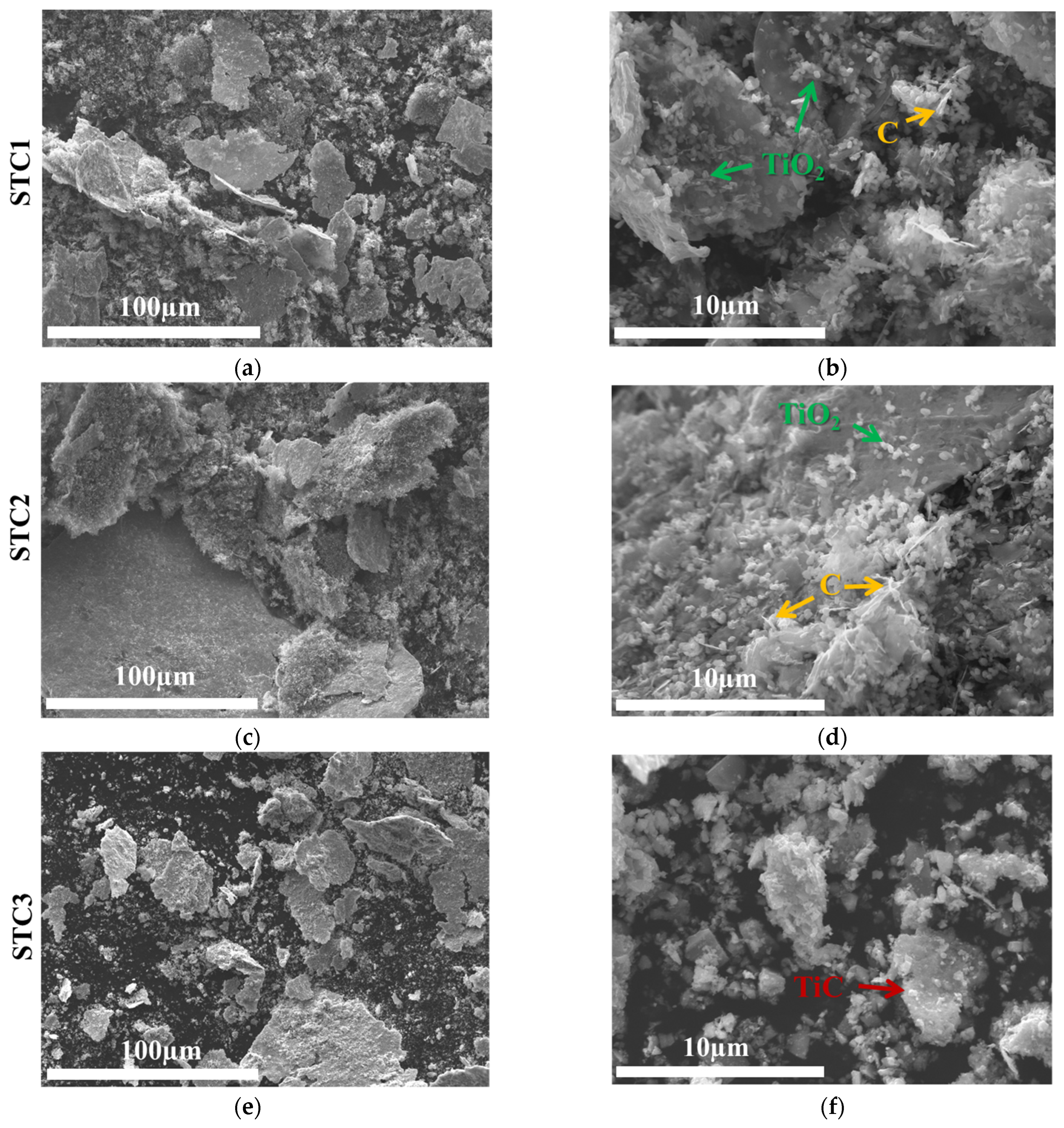
Figure 1. SEM images of powders after 72 h of ball milling: (a,b) powder for in-situ synthesis of TiC with a low weight percentage of graphite; (c,d) powder for in-situ synthesis of TiC with a high weight percentage of graphite; (e,f) powder with ex-situ-synthesized TiC (low weight percentage); (g,h) powder with ex-situ synthesized TiC (high weight percentage).
Coatings 15 00658 g001aCoatings 15 00658 g001b
Figure 2. XRD patterns of feedstock powders after 72 h of ball milling.
Coatings 15 00658 g002
Figure 3. XRD patterns of the composite hardfacings STC1 (low C), STC2 (high C), STC3 (low TiC), STC4 (high TiC), and the reference steel hardfacing.
Coatings 15 00658 g003
Figure 4. SEM images and EDS analysis of the hardfacing microstructure: (a) STC1 (low C), (b) STC2 (high C), (c) STC3 (low TiC), (d) STC4 (high TiC), and (e) steel.
Coatings 15 00658 g004aCoatings 15 00658 g004b
Figure 5. Average Vickers surface hardness of the hardfacings: STC1 (low C), STC2 (high C), STC3 (low TiC), STC4 (high TiC), and the reference steel hardfacing.
Coatings 15 00658 g005
Figure 6. Average weight loss of hardfacings at 20 m/s, 50 m/s, and 80 m/s impact velocity under a 30° impact angle.
Coatings 15 00658 g006
Figure 7. Average weight loss of hardfacings at 20 m/s, 50 m/s, and 80 m/s impact velocity under a 90° impact angle.
Coatings 15 00658 g007
Figure 8. Mapping of STC2 hardfacing after the erosive wear test at 20 m/s impact velocity under a normal impact angle (90°).
Coatings 15 00658 g008
Figure 9. The morphologies of the worn surfaces of the hardfacings under a 30° impact angle: (a) STC1 hardfacing at 20 m/s, (b) STC1 hardfacing at 50 m/s, (c) STC2 hardfacing at 20 m/s, (d) STC2 hardfacing at 50 m/s, (e) STC3 hardfacing at 20 m/s, (f) STC3 hardfacing at 50 m/s, (g) STC4 hardfacing at 20 m/s, (h) STC4 hardfacing at 50 m/s, (i) steel at 20 m/s, and (j) steel at 50 m/s impact velocity.
Coatings 15 00658 g009aCoatings 15 00658 g009b
Figure 10. The morphologies of the worn surfaces of the hardfacings under a 90° impact angle: (a) STC1 hardfacing at 20 m/s, (b) STC1 hardfacing at 50 m/s, (c) STC2 hardfacing at 20 m/s, (d) STC2 hardfacing at 50 m/s, (e) STC3 hardfacing at 20 m/s, (f) STC3 hardfacing at 50 m/s, (g) STC4 hardfacing at 20 m/s, (h) STC4 hardfacing at 50 m/s, (i) steel at 20 m/s, and (j) steel at 50 m/s impact velocity.
Coatings 15 00658 g010aCoatings 15 00658 g010b
Figure 11. The morphologies of the worn surfaces of the hardfacings at 80 m/s impact velocity: (a) STC1 hardfacing under 30°, (b) STC1 hardfacing under 90°, (c) STC2 hardfacing under 30°, (d) STC2 hardfacing under 90°, (e) STC3 hardfacing under 30°, (f) STC3 hardfacing under 90°, (g) STC4 hardfacing under 30°, (h) STC4 hardfacing under 90°, (i) steel under 30°, and (j) steel under 90° impact angle.
Coatings 15 00658 g011aCoatings 15 00658 g011b
Table 1. Designation and chemical composition of the powders.
Powders/HardfacingsChemical Composition of Feedstock Powders and Hardfacings, wt.%
SteelAISI 316L: 0.03 C, 17.5 Cr, 13 Ni, 2.7 Mo, bal. Fe
STC143.3 AISI 316L, 38.6 TiO2, 18.1 graphite
STC240.4 AISI 316L, 36.0 TiO2, 23.6 graphite
STC365.4 AISI 316L, 34.6 TiC
STC455.8 AISI 316L, 44.2 TiC
Table 2. Erosion test conditions.
Erosion Condition CategoryExperimental Setting
Solid erodentQuartz sand
Erodent particle size (mm)0.2–0.3
Erodent mass (kg)run-in: 6
erosion wear test: 15
Total: 21
Impact angle (°)30; 90
Impact velocity (m/s)20; 50; 80
Disclaimer/Publisher’s Note: The statements, opinions and data contained in all publications are solely those of the individual author(s) and contributor(s) and not of MDPI and/or the editor(s). MDPI and/or the editor(s) disclaim responsibility for any injury to people or property resulting from any ideas, methods, instructions or products referred to in the content.