Article

Influence of the Surface Rolling Process on the Tribological and Electrical Behavior of T2 Copper Elastic Contact Pairs

1
School of Materials Science and Engineering, Henan University of Science and Technology, Luoyang 471023, China
2
National United Engineering Laboratory for Advanced Bearing Tribology, Henan University of Science and Technology, Luoyang 471023, China
3
Jonhon Optronic Technology Co., Ltd., Luoyang 471023, China
*
Author to whom correspondence should be addressed.
Coatings 2025, 15(5), 615; https://doi.org/10.3390/coatings15050615
Submission received: 19 April 2025 / Revised: 15 May 2025 / Accepted: 20 May 2025 / Published: 21 May 2025
(This article belongs to the Section Surface Characterization, Deposition and Modification)

Abstract

:
Given the significant impact of the initial surface layer of materials on their tribological performance, this study uses a wire–plate reciprocating friction pair to investigate the effects of surface mechanical rolling process on the elastic current-carrying friction performance. The plate specimens were subjected to rolling processing with varying feed rates under different load conditions, using a self-designed current-carrying friction and wear testing machine. The results show that as the feed rate and load increase, the contact resistance varies within the range of 0.0065 Ω to 0.0310 Ω, with a standard deviation ranging from 0.01 Ω to 0.07 Ω, indicating good electrical conductivity. As the feed rate of the surface mechanical rolling increases, the wear rate of the material significantly decreases. Under all test conditions, the material wear marks exhibit plowing wear, and with the increase in surface mechanical rolling feed rate, the occurrence and intensification of adhesive wear are delayed. When the feed rate is 100 μm and the load is 0.025 N, the material wear rate is the lowest, reduced by 63.1% compared to the untreated condition.

1. Introduction

Current-carrying friction pairs, such as plug connectors and electrical contacts, are widely used in electronic devices, the automotive industry, and aerospace applications [1,2,3]. As fundamental components within complex systems, they are employed in large quantities. For instance, a single fighter jet typically incorporates over a thousand connector assemblies, while the propulsion module and power system of the Shenzhou spacecraft utilize at least 500 sets of connectors [4,5]. Consequently, the high reliability of each individual connector pair is a critical factor in ensuring the overall reliability of the system [6]. As a result, the influence of various factors on their performance has become a key focus of research.
Extensive research has been conducted by scholars on the factors influencing the performance of electrical connectors, including energized duration, surface roughness, material composition, and sliding distance. Ren W. et al. [7] continuously monitored parameters such as contact resistance variation over time and spring stress relaxation, revealing the degradation characteristics of contact resistance and the failure mechanisms of electrical contacts. Yang Z. et al. [8] studied the impact of initial surface roughness on the early-stage performance of elastic current-carrying friction pairs. Their findings indicated that the service life of the contact pair decreases with decreasing surface roughness and load. Lu J. [9] investigated the current-carrying and mechanical performance of gradient Cu–graphite composites under different rotational speeds. Results showed that with increasing speed, the wear rate of the composite first decreased and then increased, while the current-carrying efficiency and stability initially increased and then declined. At a speed of 1000 r/min, the composite exhibited optimal electrical and mechanical performance. Liu X. [10] examined the influence of contact line spacing in the bonded section of anchor devices on the wear mechanisms between carbon sliding plates. The study found that friction pairs with smaller center distances exhibited lower contact stress, minimized dynamic contact force fluctuations, and a friction coefficient that decreased initially before increasing. Moreover, the contact resistance increased continuously with sliding distance. N. Tyrer et al. [11] explored the tribological behavior of Sn/Cu composite coatings with varying thicknesses. It was found that thin coatings consisting solely of copper without a tin overlay exhibited the lowest wear, whereas thicker copper layers significantly increased wear.
The mechanical lifespan of connectors typically ranges from 50 to 1000 cycles [12]. The use of noble metal-coated materials (with micron-level thickness) [13] in the friction pair is limited in its running-in process, while pairs using base metals prefer to avoid the running-in process due to economic considerations. Therefore, the initial surface condition of the material, such as surface stress, becomes an important factor affecting the performance of the friction pair.
Thus, this paper uses a wire–plate reciprocating friction pair to conduct rolling processing of plate samples with varying feed rates under different load conditions and investigates the effect of surface mechanical rolling process on elastic current-carrying friction performance using a self-designed current-carrying friction and wear testing machine. This study investigates the impact of surface mechanical rolling process on the current-carrying performance and wear resistance of connector-type elastic friction pairs, providing references for improving connector performance in engineering applications.

2. Materials and Methods

2.1. Materials

In this study, a wire–plate elastic friction pair was employed, utilizing a commercially available brass wire specimen (H62, Luoyang Copper Processing Group Co., Ltd., composition detailed in Table 1) with a diameter of Φ 0.4 mm. The plate specimen comprised a commercially available copper bar (T2, Luoyang Copper Processing Group Co., Ltd., composition detailed in Table 1) with a diameter of Φ 70 mm. The copper bar was sectioned into a copper block with dimensions of Φ 70 × 30 mm using electrical discharge machining (EDM). Subsequently, surface treatment was applied to the copper block using the surface mechanical rolling technique with feeds of 50 μm and 100 μm, respectively. The treated specimens were further processed into copper plates, with dimensions of 25 × 25 × 2 mm through EDM wire cutting, in preparation for reciprocating sliding current-carrying friction experiments.
Prior to testing, the plate specimens were polished using a grinding–polishing machine (MOPAO4S, Laizhou Veiyee Testing Equipment Manufacturing Co., Ltd.), followed by ultrasonic cleaning in anhydrous ethanol for 5 min. The specimens were then thoroughly dried to ensure surface cleanliness. After treatment, the surface roughness of the samples reached Ra 0.2 μm.
Mechanical surface rolling was performed on the plate specimen (see schematic in Figure 1). The plate specimen was rotated by the main spindle at a speed of v1 = 1000 r/min. The rolling tool consisted of a WC/Co ball with a diameter of 8 mm. Tool feed was controlled via a hydraulic system. Contact between the tool and the specimen was determined when the contact pressure reached 0.25 MPa, after which feeding commenced. Once the predetermined feed amount was reached, rolling was carried out. The rolling path extended radially from the center of the specimen toward the edge, with a tool lateral displacement speed of v2 = 3 mm/s. The rolling process was repeated three times, with no additional feed applied during the second and third passes.

2.2. Methods

The experiment was carried out using a self-developed micro-sliding current-carrying friction tester, as illustrated in Figure 2. A direct current constant–current source was employed as the power supply. The experimental parameters were as follows: the reciprocating sliding distance was 5 mm, the reciprocating frequency was 1 Hz, and the total number of cycles was 1000. The total test duration was 500 s, corresponding to 500 reciprocating strokes. The applied current was 2 A, and the normal loads were set to 0.025 N, 0.05 N, 0.075 N, 0.1 N, and 0.125 N, respectively.
A wire-on-plate friction configuration was adopted, as illustrated in Figure 2. The wire specimen was bent to form an arc at an angle of 60°, with the apex of the arc oriented perpendicularly to the surface of the plate specimen. The contact interface between the wire and the plate formed an arc with a radius of 2.5 mm. Reciprocating sliding motion of the plate specimen was driven by a crank–linkage mechanism.
After the friction and wear tests, an optical microscope was used to examine microstructural changes in the cross-section of the material subjected to mechanical surface rolling. The cross-sectional hardness of the rolled copper rod was measured using an HV-1000 microhardness tester under a load of 100 g and a dwell time of 10 s. Hardness measurements were taken at 20 μm intervals from the surface inward until the hardness value approached that of the substrate. The three-dimensional morphology of the wear scars was analyzed using a Slynx2 compact 3D surface profilometer (Barcelona, Spain). The worn surface of the plate specimens was observed using a JSM-5610LV scanning electron microscope (SEM) manufactured by JEOL Ltd. (Tokyo, Japan).

2.3. Data Processing

2.3.1. Friction Coefficient

The friction coefficient includes both the dynamic friction coefficient and the average friction coefficient. The dynamic friction coefficient reflects the motion and fluctuation of the friction pair during the friction process, and it provides a more intuitive view of the friction coefficient changes at a specific moment during the motion of the friction pair. The average friction coefficient represents the mean value of the dynamic friction coefficient throughout the motion of the friction pair. It allows for easier comparison of friction coefficients across different materials, facilitating research characterization.
The dynamic friction coefficient is calculated as follows:
μ i = f i F i
where f i is the friction force at moment i, (N), and F i is the positive pressure at moment i, (N).
The average coefficient of friction refers to the mean value of the ratio between the tangential (frictional) force and the normal force at the contact interface over a sliding process. The specific calculation formula is as follows:
u - = 1 n i = 1 n f i F i
where u ¯ is the average friction coefficient, f i is the friction force at moment i, (N), and f i is the positive pressure at moment i, (N).

2.3.2. Wear Rate

The wear rate refers to the amount of mass loss of the friction material per unit sliding distance, and it is an important parameter for evaluating the tribological performance of materials. The specific formula is as follows:
w = V Ps
where W–for the wear rate, (mm3/Nm); P–normal load, (N); V–wear volume, (mm3), s–reciprocating distance, (m).

3. Results

3.1. Effect of Surface Mechanical Rolling on the Hardness of T2 Copper Plate

Figure 3 gives the microhardness curves from the surface of the rolling process to the interior after the mechanical rolling process. From the figure, it can be seen that the hardness of the surface layer is about 110 HV, and the thickness is about 50~60 μm; from the rolling machining surface to the interior, the microhardness value first decreases slowly, then decreases sharply, and finally tends to flatten out and gradually converge with the internal hardness; with the increase in rolling feed, the hardness and thickness of the deformation zone are slightly increased.

3.2. Effect of Surface Mechanical Rolling on the Carrier Friction and Wear Performance of T2 Copper Plates

Figure 4 gives the trend of contact resistance with surface mechanical rolling feed under different load conditions. From the figure, it can be seen that with the increase in load, the contact resistance is gradually decreasing; with the increase in surface mechanical rolling feed, the contact resistance increases. Under the test conditions, the average value of contact resistance varies in the range of 0.0065 Ω~0.0310 Ω, and the standard deviation is about 0.01 Ω~0.07 Ω.
The curves of variation in friction coefficient with surface mechanical rolling feed under different loading conditions are given in Figure 5a. It can be seen from the figure that the coefficient of friction decreases gradually with the increase in load. The friction coefficient increases and then decreases with the increase in surface mechanical rolling feed. All the average friction coefficients fluctuate in the range of 0.0808 to 0.3196.
Figure 5b gives the variation curve of wear rate with surface mechanical rolling feed under different loading conditions. From the figure, it can be seen that the wear rate gradually increases with the increase in load; the wear rate gradually decreases with the increase in surface mechanical rolling feed; at smaller loads, the surface mechanical rolling treatment has a significant effect on the wear rate, and the wear rate is lowest and 63.1% lower than the unprocessed one when the surface mechanical rolling feed is 0.1 mm and the load is 0.025 N. The wear rate of the surface mechanical rolling is 0.025 N. The wear rate is lower than the unprocessed one, and the wear rate is lower than the unprocessed one.

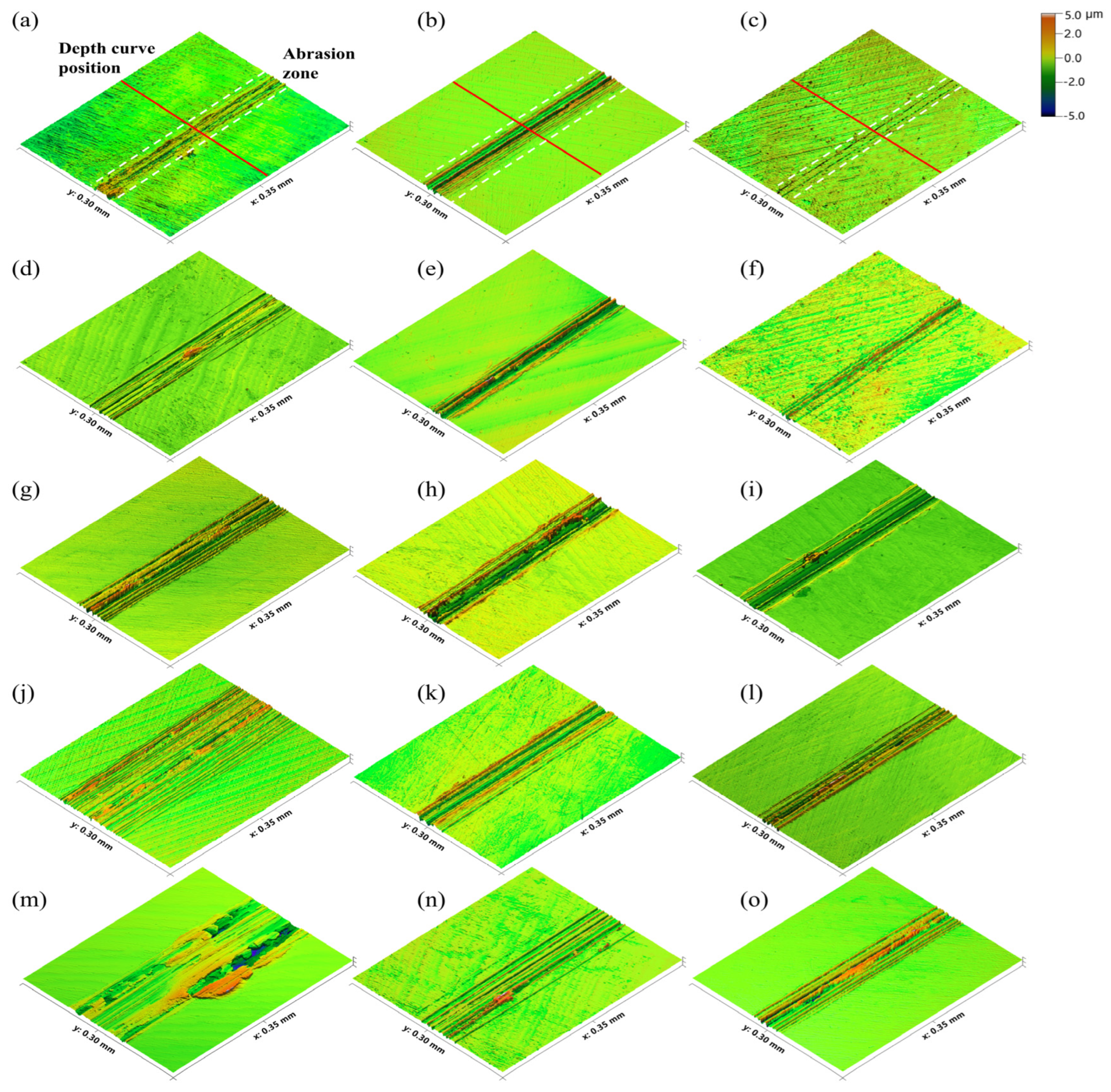
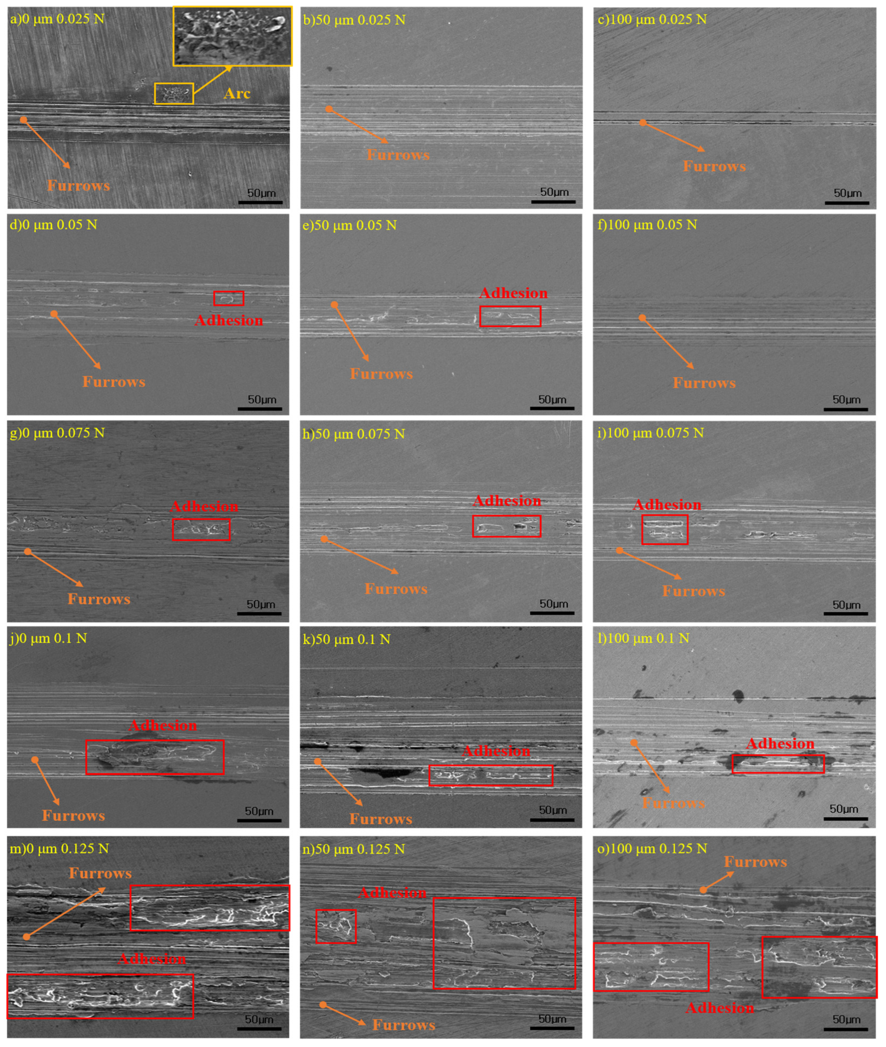
3.3. Effect of Surface Mechanical Rolling Feed Depth on the Current-Carrying Friction and Wear Behavior of T2 Copper Plates

Figure 6 presents the three-dimensional morphologies of wear scars on the plate specimens. From top to bottom, it is evident that wear scar width increases with increasing load; from left to right, wear scar width decreases with increasing rolling feed amount. On the leftmost specimen, which was not subjected to surface rolling, significant material accumulation is observed along the edges of the wear scar. In contrast, for the rightmost specimen with a feed amount of 100 μm, there is less accumulation at the scar edges, and the wear boundary appears more uniform. This is because, during the friction and wear process, the normal load directly affects the real contact area [14]. As the load increases, the contact stress rises, making the material surface more susceptible to plastic deformation. This results in greater material removal or displacement toward the edges of the wear scar, causing pronounced accumulation. In contrast, the rolled specimens develop a high-hardness strengthened layer (approximately 50~60 μm thick, as shown in Figure 3) due to plastic deformation and grain refinement induced by the rolling process. This layer enhances the shear strength of the surface and improves its resistance to the propagation of plowing grooves caused by sliding friction. Additionally, the residual compressive stress field offsets the tensile stresses generated by external loads, thereby inhibiting the expansion of wear scars. As a result, unrolled specimens exhibit severe material accumulation at wear scar edges, whereas rolled specimens show more regular and cleaner wear boundaries.
Figure 7a illustrates the variation curves of wear scar depth under different conditions. As shown, the wear depth increases with increasing load, while it decreases with greater surface mechanical rolling feed depth. When the feed depth is 100 μm and the load is 0.025 N, the minimum wear depth is observed −34% lower than that of the untreated specimen. Figure 7b shows the wear scar profiles extracted from the depth positions indicated in Figure 6a–c. It is evident that both the width and depth of the wear scars decrease as the surface mechanical rolling feed depth increases.
Figure 8 presents SEM images of worn surfaces under different conditions. As shown, plowing marks are observed on all worn surfaces after testing, with occasional arc erosion visible, such as in Figure 8a [8]. As the applied load increases, adhesive wear becomes more dominant, and the wear mechanism gradually transitions from plowing-dominated to adhesive-dominated with secondary plowing. With increasing surface rolling feed amount, the width and depth of the plowing grooves decrease. As shown in Figure 8d–f, only plowing wear is observed in Figure 8f. Under the same load conditions, both adhesive and plowing wear are observed in Figure 8d,e, with more extensive adhesive wear areas in Figure 8d than in Figure 8e. In Figure 8g–i, both adhesive and plowing wear are present. Combined with the microhardness analysis shown in Figure 3, the surface mechanical rolling process is found to form a strengthened layer approximately 50~60 μm thick on the copper surface, significantly enhancing the material’s resistance to shear and compressive stresses. In addition, residual compressive stress helps suppress local plastic deformation and tearing induced by contact loading. Therefore, an increased rolling feed amount delays the onset of adhesive wear to a certain extent.

4. Discussion

The mechanical lifetime of current-carrying friction pairs, exemplified by connector pairs, typically ranges from only 50 to 1000 cycles—significantly shorter than the wear durations considered in classical tribological theory [15,16], and insufficient to reach the low-wear regime (e.g., Region II in Figure 9) [17]. Moreover, due to the limitations of surface processing techniques such as electroplating, the resulting coatings are typically on the micrometer scale and often fail to undergo an effective running-in process. As a result, the surface properties of the material play a critical role in determining its service performance.
Surface rolling processing causes plastic deformation of the material’s surface metal, resulting in work-hardening phenomena (Figure 3). Residual compressive stresses are left in the surface layer after processing is completed [18,19].
After surface mechanical rolling, the changes in the surface layer of the material result in a slight increase in its electrical resistance. The mechanical rolling process leads to significant grain refinement in the surface layer and induces a residual stress field. These microstructural changes result in enhanced electron–lattice scattering, which in turn increases the material’s electrical resistance [20]. As the rolling feed increases, the degree of plastic deformation intensifies, resulting in a greater increase in resistance. Due to the limitation of the method of measuring the contact resistance, this change in resistance is accounted for in the contact resistance during the measurement process, and therefore, the phenomenon of increasing contact resistance with the increase in rolling feed occurs.
Various wear mechanisms can occur in current-carrying friction pairs, typically including mechanical wear, arc erosion, and corrosive wear. Among these, corrosive wear—primarily due to oxidation—plays a minor role during sliding electrical contact. Under the present experimental conditions, the dominant damage mechanism during sliding current-carrying friction is mechanical wear, mainly characterized by furrows and adhesive tearing, as shown in the furrow and adhesion regions in Figure 8. Occasional arc erosion can also be observed, indicated by the “Arc” region in Figure 8.
Surface hardening occurs when the material is mechanically rolled on the surface while the ability of the material to resist shear deformation increases. The hardened material is more difficult to undergo plastic deformation, reducing material transfer due to shear and extrusion, significantly reducing the depth and width of the furrows. At the same time, after the mechanical rolling process, there is residual compressive stress in the surface layer. In the friction wear process, the residual compressive stress will be released, which can effectively offset the applied load on the surface of the material as part of the tensile stress to resist in the friction wear process due to the contact stress cyclic action caused by the plastic deformation; this inhibits the tearing damage [21]. Therefore, as the rolling feed increases, the damage to the material decreases.
In applications such as plugs and electrical contacts, the amount of contact material used is minimal—for instance, precious metal plating layers are typically only a few micrometers thick, and the hardened layer produced in this study is approximately 300 μm. From the perspective of the entire conductive circuit, it is often not necessary for the contact resistance to be minimized [22]. Therefore, although the surface mechanical rolling process leads to an increase in contact resistance, it substantially enhances the service life of the connector. For example, under experimental conditions with a load of 0.025 N and a rolling feed of 100 μm, the contact resistance increased by 77%, while the wear rate decreased by 63.1%, and the wear life was extended by nearly threefold. These results offer practical guidance for real-world operating conditions.

5. Conclusions

(1)
Under the experimental conditions, the contact resistance varied within the range of 0.0065 Ω to 0.0310 Ω with changes in surface rolling feed amount and applied load. The wear rate gradually decreased with increasing feed amount; at a feed of 100 μm and a load of 0.025 N, the material exhibited the lowest wear rate, which was reduced by 63.1% compared to the untreated specimen.
(2)
Under all test conditions, plowing was consistently observed as the primary wear mechanism, with occasional occurrences of arc erosion. As the rolling feed amount increased, the wear scar width decreased, and both the onset and progression of adhesive wear were relatively delayed.
(3)
From an engineering application perspective, for connectors that are not highly sensitive to contact resistance, surface mechanical rolling can prolong service life without compromising electrical performance. These findings provide practical guidance for reducing wear under current-carrying friction conditions.
(4)
The current-carrying tribological performance of connectors is influenced not only by post-processing treatments but also by the initial forming methods (e.g., stamping), which affect the surface microstructure and properties. Future research could focus on the relationship between forming techniques and the resulting surface condition and wear behavior under current-carrying friction. This direction is expected to contribute positively to the optimization of connector performance.

Author Contributions

Methodology, Z.Y.; validation, M.Z.; investigation, X.W., W.L., X.T., K.H. and Y.Z.; data curation, M.Z. and X.W.; writing—original draft, Z.Y. and M.Z.; writing—review and editing, Z.Y.; visualization, M.Z.; supervision, Y.Z.; project administration, X.W.; funding acquisition, Z.Y. and Y.Z. All authors have read and agreed to the published version of the manuscript.

Funding

This work was supported by the National Natural Science Foundation of China (U1804252) and the Key Scientific Research Project of Henan Province (22A430021).

Institutional Review Board Statement

Not applicable.

Informed Consent Statement

Not applicable.

Data Availability Statement

The original contributions presented in this study are included in the article. Further inquiries can be directed to the corresponding author.

Conflicts of Interest

Author Xiaowei Wang was employed by the company Jonhon Optronic Technology Co., Ltd. The remaining authors declare that the research was conducted in the absence of any commercial or financial relationships that could be construed as a potential conflict of interest.

References

  1. Ding, R.; Ni, J.; Huang, S. Multi-physical field coupling contact resistance study of electrical connectors. Electrotech. Electr. 2023, 7, 21–26. [Google Scholar]
  2. Zhao, L.; Deng, T.; Kong, Z.; Gong, D.; Yuan, Y. Failure Analysis and Targeted Quality Assurance Measures for Aerospace Electrical Connectors. Electromech. Compon. 2024, 44, 34–38. [Google Scholar]
  3. Song, J.; Hilmert, D.; Kiel, F. Mechanisms of failure and state analysis of electrical connectors in automobiles. Eng. Fail. Anal. 2025, 173, 109427. [Google Scholar] [CrossRef]
  4. Editorial Board of China Journal of Highway and Transport. Review of Chinese Automotive Engineering Research 2023. China J. Highw. Transp. 2023, 36, 1–192. [Google Scholar]
  5. Ren, W.; Jiao, Y.; Zhai, G. Review of Fretting Wear for Electrical Connector. Electromech. Compon. 2010, 30, 28–38. [Google Scholar]
  6. Wang, N. Reliability Analysis of Electrical Connector Contact Pieces; Xi’an Technological University: Xi’an, China, 2020. [Google Scholar]
  7. Yang, X.; Wu, C.; He, Y.; Zhang, C.; Ren, W. Research on Contact Resistance Degradation Mechanisms of Relay with Contact Bridge Structure Under Continuous Current Loading. Electr. Energy Manag. Technol. 2025, 1–5. [Google Scholar] [CrossRef]
  8. Yang, Z.; Li, W.; Zheng, X.; Zhao, M.; Zhang, Y. The Influence of Initial Surface Roughness on the Current-Carrying Friction Process of Elastic Pairs. Materials 2025, 18, 370. [Google Scholar] [CrossRef] [PubMed]
  9. Lu, J.; Zheng, B.; Guo, B.; Wang, Y.; Li, W.; Liu, Y. The current-carrying damage mechanism of gradient copper-based composite ceramics with different sliding speeds. Ceram. Int. 2025, 51, 3837–3845. [Google Scholar] [CrossRef]
  10. Lu, X.; Zhang, W.; Xiao, Q.; Zhong, Y.; Cao, Y.; Guan, X.; Zhang, S.; Zheng, Y.; Gao, M.; Yang, W.; et al. Study on the effect of different structural parameters on the wear mechanism in the anchor-segment joint of the rigid overhead catenary. Tribol. Int. 2024, 191, 109108. [Google Scholar] [CrossRef]
  11. Tyrer, N.; Yang, F.; Barber, G.; Pang, B.; Wang, B. Tribological Behavior of Electrical Connector Coatings Under Reciprocating Motion. J. Tribol. 2022, 144, 91401. [Google Scholar] [CrossRef]
  12. GB/T 41036-2021; General Specification for Super High-Low Temperature Circular Electrical Connector for Space Applications: GB/T 41036-2021. Standards Press of China: Beijing, China, 2021.
  13. Yang, F. Electrical connector industry basic common technology outlook. Electromechanical Compon. 2023, 43, 53–60+63. [Google Scholar]
  14. Liang, X.M.; Xing, Y.Z.; Li, L.; Yuan, W.; Wang, G. An experimental study on the relation between friction force and real contact area. Sci. Rep. 2021, 11, 20366. [Google Scholar] [CrossRef] [PubMed]
  15. Greenwood, J.A.; Williamson, J.B.P. Contact of nominally flat surfaces. Proc. R. Soc. Lond. Ser. A Math. Phys. Sci. 1966, 295, 300–319. [Google Scholar]
  16. Kogut, L.; Etsion, I. Elastic-plastic contact analysis of a sphere and a rigid flat. J. Tribol. 2002, 124, 305–311. [Google Scholar] [CrossRef]
  17. Wen, S.; Huang, P.; Tian, Y. Principles of Tribology, 5th ed.; Tsinghua University Press: Beijing, China, 2018; pp. 297–298. [Google Scholar]
  18. Nie, J.P.; Jiang, Y.; Guan, Q. Effect of ultrasonic surface rolling treatment on the friction and wear performance of 7075 aluminum alloy. J. Cent. South Univ. Nat. Sci. Ed. 2025, 56, 443–457. [Google Scholar]
  19. Zheng, K.; Zhao, X.; Mou, G.; Ren, Z. Surface Quality, Friction and Wear Properties of TC11 Titanium Alloy Strengthened Using Ultrasonic Rolling. J. Mech. Eng. 2024, 60, 137–151. [Google Scholar]
  20. Zhuang, H.; Ji, D.; Shen, M.; Liu, S.; Xiao, Y.; Xiong, G. Tribological behavior of T2 copper induce by surface mechanical rolling treatment under current carrying condition. J. Chin. Nonferrous Met. 2023, 33, 521–530. [Google Scholar]
  21. Sun, J.; Zhang, Y.; Sun, Z.; Yu, T.; Wang, G. Microstructure and tribological property of laser cladding Stellite 6 alloy by laser remelting and ultrasonic surface rolling. Surf. Coat. Technol. 2025, 495, 131560. [Google Scholar] [CrossRef]
  22. Yang, Z.; Zhang, Y.; Chen, F.; ShangGuan, B.; Li, X.; Tian, L. Overview of Cu-C Sliding Contact Materials with Electrical Current Produced by Powder Metallurgy. Mater. Rev. 2012, 26, 106–110+125. [Google Scholar]
Figure 1. Schematic diagram of surface mechanical rolling treatment processing.
Coatings 15 00615 g001
Figure 2. Schematic diagram of current-carrying friction test.
Coatings 15 00615 g002
Figure 3. Hardness curves at different depths from the surface of the specimen.
Coatings 15 00615 g003
Figure 4. Trend of contact resistance under different conditions.
Coatings 15 00615 g004
Figure 5. Variation trends of friction coefficient and wear rate under different conditions: (a) friction coefficient; (b) wear rate.
Coatings 15 00615 g005
Figure 6. Three-dimensional morphology of the wear surface on the plate specimen. (a) 0 μm 0.025 N; (b) 50 μm 0.025 N; (c) 100 μm 0.025 N; (d) 0 μm 0.05 N; (e) 50 μm 0.05 N; (f) 100 μm 0.05 N; (g) 0 μm 0.075 N; (h) 50 μm 0.075 N; (i) 100 μm 0.075 N; (j) 0 μm 0.1 N; (k) 50 μm 0.1 N; (l) 100 μm 0.1 N; (m) 0 μm 0.125 N; (n) 50 μm 0.125 N; (o) 100 μm 0.125 N.
Coatings 15 00615 g006
Figure 7. Variation curves of wear scar depth. (a) The variation curves of wear scar depth with rolling feed rate and applied load; (b) Under a load of 0.025 N, the curves of wear scar width and depth as functions of rolling feed rate.
Coatings 15 00615 g007
Figure 8. SEM images of the friction and wear surfaces of T2 copper plates under different conditions.
Coatings 15 00615 g008
Figure 9. Wear process curve. I. Running-in wear stage: During the initial operation of the tribo-pair, the wear rate gradually decreases with time. This stage is characterized by surface adaptation and the removal of asperity peaks. II. Steady-state wear stage: Following the running-in period, the contact surfaces reach a stabilized condition where the wear rate remains nearly constant. This stage represents the normal and intended operational phase of the tribo-system. III. Severe wear stage: At this point, the wear rate increases rapidly with time, leading to a sharp degradation of working conditions and ultimately resulting in catastrophic failure of the components.
Coatings 15 00615 g009
Table 1. Chemical composition list of sample (wt. %).
MaterialsCuZnPbSbSFeImpurities
T299.95-0.0050.0020.0050.005Bal.
H6260.5–63.5Bal.≤0.08≤0.005-≤0.15≤0.5
Disclaimer/Publisher’s Note: The statements, opinions and data contained in all publications are solely those of the individual author(s) and contributor(s) and not of MDPI and/or the editor(s). MDPI and/or the editor(s) disclaim responsibility for any injury to people or property resulting from any ideas, methods, instructions or products referred to in the content.

