Article

Tribological Performance of TiN–WS2 Soft–Hard Multifunctional Composite Coatings Deposited by Magnetron Sputtering

1
School of Mechatronic Engineering, Xi’an Technological University, Xi’an 710021, China
2
Information Center of China North Industries Group Corporation, Beijing 100089, China
3
Research Center for Semiconductor Materials and Devices, Shaanxi University of Science and Technology, Xi’an 710021, China
*
Authors to whom correspondence should be addressed.
Coatings 2025, 15(5), 596; https://doi.org/10.3390/coatings15050596 (registering DOI)
Submission received: 15 April 2025 / Revised: 11 May 2025 / Accepted: 15 May 2025 / Published: 17 May 2025

Abstract

:
Titanium nitride (TiN) is a widely used industrial hard coating material, known for its excellent hardness and chemical stability. However, its relatively high coefficient of friction (COF) often leads to interfacial heat accumulation and adhesive wear during service, limiting its applicability in high-temperature tribological environments. To enhance its tribological performance, a TiN–WS2 soft–hard composite coating was fabricated on cemented carbide substrates using reactive co-sputtering magnetron deposition. By adjusting the sputtering parameters and target power ratio, a synergistic deposition of the hard (TiN) and lubricating (WS2) phases was achieved and compared with a pure TiN coating. The results revealed that the incorporation of WS2 significantly reduced the COF at both room temperature (25 °C) and an elevated temperature (200 °C), with the average values decreasing from 0.61 to 0.39 at 25 °C and from 0.53 to 0.36 at 200 °C. A white light interferometry analysis showed that the TiN–WS2 coating exhibited narrower wear tracks and less surface damage than TiN at elevated temperatures, demonstrating superior friction-reducing and wear-resistant capabilities. In terms of mechanical properties, the composite coating showed a reduction in the hardness, the reduced elastic modulus (Er), and the adhesion strength by 27.3%, 19.8%, and 9.5%, respectively, compared to pure TiN. These findings indicate that the introduction of a quantitatively controlled lubricating WS2 phase allows for a balance between nanoscale hardness and wear resistance, offering promising potential for engineering applications under complex working conditions.

1. Introduction

Titanium nitride (TiN) is a representative hard coating material that has been widely applied in the surface reinforcement of cutting tools [1] and die protection [2], owing to its excellent hardness (>20 GPa) [3], superior wear resistance [4], and outstanding chemical stability [5]. In addition to tool and die protection, TiN coatings have demonstrated broad application potential in various fields such as tribological interfaces, biomedical implants, and environmentally sustainable surface technologies. For instance, recent studies have explored the application of TiN coatings in advanced tribological systems [6], corrosion- and wear-resistant functional coatings [7], and low-impact manufacturing processes [8]. These applications highlight the increasing demand for TiN-based multifunctional coatings capable of combining a high mechanical durability with tailored frictional and environmental properties. However, its relatively high coefficient of friction under high-speed or heavy-load sliding conditions often leads to interfacial heat accumulation and adhesive wear [9,10,11], significantly reducing its service life in complex tribological environments [12].
To simultaneously achieve a high hardness and a low friction, researchers have incorporated solid lubricating phases—such as carbon (C), molybdenum disulfide (MoS2), and tungsten disulfide (WS2)—to construct soft–hard composite coatings [13,14,15]. Carbon-based materials like diamond-like carbon (DLC) offer a low friction and a moderate hardness [16], but their tribological performance is susceptible to degradation under high humidity and may suffer from structural reconstruction [17]. MoS2 performs well in a vacuum or dry environments, but exhibits a marked decline in lubricating performance in humid conditions [18]. In contrast, WS2 has attracted extensive attention due to its layered crystal structure and excellent oxidation resistance, enabling it to maintain low friction across a wide range of temperatures and humidities [19,20,21]. Nevertheless, as a typical soft material, WS2 exhibits an inherently low hardness and a weak adhesion to substrates, making it unsuitable for high-load applications unless combined with a hard phase to balance the mechanical strength and tribological performance [22,23].
Common strategies for integrating WS2 and TiN include multilayer architectures (e.g., TiN/WS2 periodic stacks) [24] and chemical vapor sulfurization [25]. However, multilayer coatings are prone to interfacial delamination under cyclic or thermal loads, while sulfurization processes often cause the thermal degradation of the substrate at elevated temperatures [26]. Magnetron co-sputtering, by contrast, offers a low-temperature, controllable approach for achieving the homogeneous deposition of hard and lubricating phases [27,28]. Several recent studies have demonstrated that TiN coatings deposited from stoichiometric TiN targets via non-reactive sputtering (i.e., without nitrogen gas) can achieve an excellent mechanical and tribological performance [29]. These efforts form a foundation for extending non-reactive deposition strategies to more complex composite systems. Although a few studies have reported the co-sputtering of TiN and WS2 under non-reactive conditions, the process remains less extensively explored compared to reactive systems. In particular, the correlation between microstructural evolution and tribological performance in such binary-target, nitrogen-free sputtering configurations lacks systematic investigation and quantitative interpretation.
To address these issues, this study proposes a non-reactive magnetron co-sputtering approach with stoichiometric control to fabricate TiN–WS2 composite coatings by simultaneously sputtering a TiN target and a WS2 target in the absence of nitrogen gas. This strategy avoids the compositional instability often caused by reactive gas fluctuations. A comparative analysis with a conventional TiN coating was carried out, with particular emphasis on the trade-off between hardness and wear resistance, aiming to provide both theoretical insights and practical guidance for the design of advanced multifunctional coatings.

2. Experiments

2.1. Equipment and Materials

Figure 1 illustrates the fundamental principle of magnetron sputtering. This process utilizes the synergistic effect of electric and magnetic fields to ignite argon gas discharge, thereby generating plasma. A large number of argon ions (Ar+) are formed within the plasma and are accelerated toward the target under the influence of the electric field. These energetic ions bombard the target surface, transferring momentum and ejecting target atoms or molecules. The sputtered species then migrate and deposit onto the substrate surface, gradually forming a dense thin-film structure.
In this study, an MSP-300B magnetron sputtering system (Beijing Chuangshi Weina Technology Co., Ltd., Beijing, China) was employed. During the deposition process, the target serves as the cathode, while the substrate acts as the anode, enabling the formation of the coating under controlled plasma conditions.
High-purity TiN (99.9%) and WS2 (99.9%) targets with dimensions of Φ60 mm × 3 mm were employed in this study. Both targets were purchased from Beijing Zhongnuo Enhanced Materials Co., Ltd. (Beijing, China). A TiN–WS2 composite coating was deposited via the co-sputtering of the two targets, allowing for the simultaneous incorporation of the hard TiN phase and the lubricating WS2 phase. The addition of WS2 was expected to enhance the interfacial adhesion between the coating and the substrate while imparting excellent friction-reducing characteristics to the composite film. To ensure deposition quality, all the targets were thoroughly characterized prior to use to confirm their chemical homogeneity and dimensional accuracy [30,31].
Table 1 summarizes the type, quantity, and geometric dimensions of the substrates used in this study, along with their specific functions in various testing procedures. The chosen substrate material was YG8 cemented carbide, which consists of tungsten carbide (WC) reinforced with an 8 wt.% cobalt (Co) binder. This material offers a favorable combination of a high hardness and an excellent impact toughness, making it suitable for high-load and high-wear applications. YG8 is widely used in rough and semi-finish machining, as well as in drilling and reaming operations under demanding conditions [32].

2.2. Experimental Methods

To ensure strong interfacial bonding during the deposition process, YG8 cemented carbide substrates were mechanically polished to achieve a low surface roughness. The measured average surface roughness (Ra) after polishing was approximately 0.025 μm, indicating a smooth surface suitable for coating adhesion. To further eliminate surface contaminants and improve cleanliness, a multistep ultrasonic cleaning procedure was employed. Specifically, the substrates were sequentially cleaned in acetone and anhydrous ethanol for 20 min each using an ultrasonic cleaner (power: 150 W, frequency: 40 kHz), followed by a 10 min ultrasonic rinse in ultrapure water (conductivity: <0.05 μS/cm) to remove residual organic solvents and fine particulates [33].
Prior to deposition, the sputtering chamber was evacuated to a high-vacuum condition to ensure the quality and density of the coating. In this study, the base pressure was reduced to 7.5 × 10⁻⁴ Pa to minimize the presence of residual gases such as oxygen, which can undesirably react with the TiN target to form TiO2, thereby weakening the stability of Ti–N chemical bonding during deposition [34]. Moreover, a high-vacuum environment increases the mean free path of gas molecules, reducing collision losses during the transport of ions and atoms, thus enhancing the sputtering efficiency and the coating quality [35,36]. After reaching the target vacuum level, argon gas was introduced at a flow rate of 30 sccm to establish a stable working atmosphere and initiate plasma generation for sputtering.
Two different deposition schemes were designed in this study: (i) single-target RF sputtering using a TiN target to fabricate a TiN coating; and (ii) dual-target magnetron co-sputtering using TiN and WS2 targets to fabricate a TiN–WS2 composite coating. The TiN target, being a conductive ceramic, was powered using a direct current (DC) source, whereas the poorly conductive WS2 target required a radio frequency (RF) power source during co-sputtering. In the co-sputtering configuration, both targets were mounted at a tilt angle of 30° with respect to the substrate, and the target-to-substrate distance was set to 100 mm to improve film uniformity and target utilization. For comparison, the TiN single-target sputtering was conducted using a vertical target configuration, with the same 100 mm target-to-substrate distance; during the deposition process, the substrate was rotated at a speed of 10 rpm to minimize the deposition flux asymmetry and local compositional segregation caused by the geometric asymmetry of the dual-target configuration [37].
Table 2 summarizes the detailed process parameters used in all deposition experiments. A DC power of 150 W and an RF power of 120 W were applied to the TiN and WS2 targets, respectively. This power combination, optimized through preliminary tests, enabled stable co-deposition and a uniform compositional distribution, forming the process basis for the subsequent film performance analysis [38].

2.3. Coating Characterisation

The surface morphology and elemental distribution of the coatings were characterized using scanning electron microscopy (SEM), energy-dispersive X-ray spectroscopy (EDS), and white light interferometry (WLI). Additionally, the mechanical properties of the coatings were evaluated through nanoindentation and scratch tests. To simulate real working conditions, reciprocating friction and wear tests were conducted at room temperature (25 °C) and an elevated temperature (200 °C) to investigate the tribological behavior of the coatings.
A field-emission scanning electron microscope (FE-SEM, ZEISS Sigma 360, Carl Zeiss, Oberkochen, Germany) was employed to observe both the surface and cross-sectional microstructures of the coatings. An elemental analysis was performed on the same instrument using energy-dispersive X-ray spectroscopy (EDX) to confirm the chemical composition of the samples.
The phase composition and crystallinity of the coatings were examined using X-ray diffraction (XRD, Smart Lab 9 kW, Rigaku Corporation, Tokyo, Japan) over a scanning range of 30° to 80° (2θ).
The mechanical properties, including the nanohardness (H) and the reduced elastic modulus (Er), were evaluated using a nanoindenter (Nano Indenter G200X, KLA Instruments, Milpitas, CA, USA). The instrument was equipped with a Berkovich diamond indenter and operated under a constant load mode with a maximum applied load of 4 mN. This loading condition ensured that the penetration depth remained within 10% of the coating thickness, thereby minimizing the substrate influence on the measured values. Since Poisson’s ratio of the coatings was not assumed, all the modulus values reported in this study refer to the reduced elastic modulus (Er). For each sample, six independent indentations were performed at different locations to ensure the representativeness and statistical reliability of the results.
The adhesion strength of the coating–substrate interface was preliminarily evaluated using a nano-scratch tester (Anton Paar GmbH, Graz, Austria) under a maximum normal load of 300 mN and a loading rate of 0.19 mN/s. For each coating, a single scratch test was conducted to provide an initial assessment of interfacial adhesion. The critical load corresponding to coating failure was determined based on the sudden change in acoustic emission (AE) signals, the discontinuity in the normal force–displacement curve, and the visible damage observed at the failure point using optical microscopy.
The tribological performance of the TiN and TiN–WS2 coatings was evaluated using a TRB³ high-temperature reciprocating tribometer (Anton Paar GmbH, Graz, Austria) at two temperatures: room temperature (25 °C) and an elevated temperature (200 °C). The tests were performed in the reciprocating sliding mode using a GCr15 bearing steel ball (diameter: 9.5 mm, surface roughness: ~0.1 μm). The test conditions were set to a normal load of 5.5 N, a sliding frequency of 2 Hz, and a stroke length of 10 mm. Each test was repeated three times under each temperature condition to ensure data reliability. The average values of the coefficient of friction and volumetric wear rate were calculated from the repeated measurements, and the corresponding standard deviations were reported to quantify the experimental variability. These tribological tests were designed to simulate realistic service conditions involving sliding motion and thermal effects, enabling a comparative assessment of the coatings’ friction and wear behavior.
The post-test surface morphology of the wear tracks was analyzed using SEM (SU-70, Hitachi Ltd., Tokyo, Japan) to evaluate the wear severity. Furthermore, the three-dimensional surface topography of the worn bearing balls was examined using a white light interferometer (WLI, Zegage Plus, Zygo Corporation, Middlefield, CT, USA) to quantitatively characterize wear scar features.

3. Results and Discussion

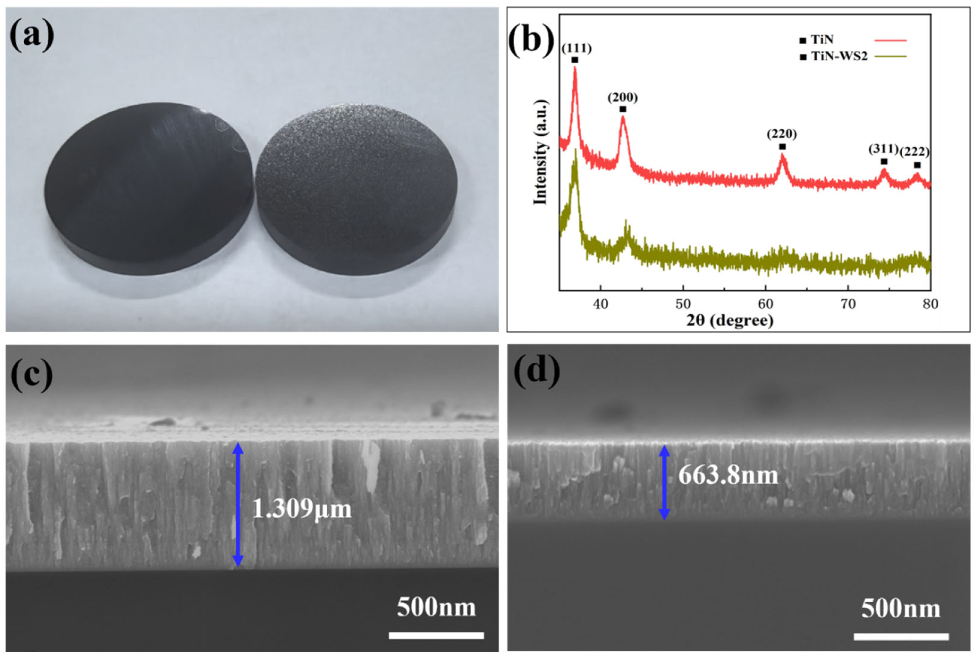
3.1. Thin Film Morphology and Structural Characterization

The surface morphology and XRD patterns of the deposited pure TiN and TiN–WS2 composite coatings are shown in Figure 2.
Figure 2a presents the macroscopic surface appearance of both coatings deposited on YG8 cemented carbide substrates. The coatings were uniformly distributed across the substrate surface, exhibiting a metallic luster and a smooth appearance, indicative of a high coating density and strong interfacial adhesion. The pure TiN coating exhibited a dark metallic luster, while the TiN–WS2 composite coating appeared gray-black, likely due to the presence of WS2. The dark appearance of the TiN coating was attributed to its microstructural and compositional characteristics. In this study, TiN was deposited under non-reactive conditions using a stoichiometric TiN target with argon as the sole sputtering gas. The EDS analysis revealed an oxygen atomic concentration of approximately 6%, and the SEM observations showed a fine-grained surface morphology. Such features are known to increase diffuse light scattering and reduce surface reflectivity, thereby contributing to the observed dark coloration. A similar phenomenon was reported by Abd El-Fattah et al., who demonstrated that oxygen incorporation and grain refinement in TiN-based films significantly influence their optical response and visual appearance [39].
Figure 2b shows the X-ray diffraction (XRD) patterns of the TiN and TiN–WS2 coatings. For the TiN coating (Curve 1), distinct diffraction peaks corresponding to the (111), (200), (220), (311), and (222) planes of face-centered cubic (FCC) TiN were observed, indicating a good crystallinity and phase purity. In contrast, the TiN–WS2 coating (Curve 2) exhibited significantly weakened and broadened diffraction peaks, suggesting a more disordered microstructure. Although the major TiN peaks were still discernible, no characteristic peaks of WS2 were detected, implying that WS2 may exist in an amorphous state. The incorporation of WS2 likely induced lattice distortion and energy dispersion, which inhibited the ordered growth of TiN grains and ultimately reduced the overall crystallinity of the coating [40].
Figure 2c,d show cross-sectional SEM images of the TiN and TiN–WS2 coatings, respectively. The TiN coating exhibited a thickness of approximately 1.31 μm, featuring a dense structure with a uniformly aligned columnar morphology. In contrast, the TiN–WS2 composite coating, with a reduced thickness of about 663.8 nm, also displayed a columnar structure. The significantly lower thickness compared to pure TiN may be attributed to the incorporation of WS2, which likely influenced the film growth rate and nucleation mechanism during the co-sputtering process. This interpretation is further supported by the XRD results, where the TiN–WS2 coating exhibited weakened diffraction peak intensities and a reduced crystallinity, indicating that WS2 incorporation affected the phase composition and crystalline quality of the coating.
As shown in Figure 3, the TiN and TiN–WS2 coatings exhibited notable differences in their surface microstructure and elemental distribution. At a scale of 1 μm (Figure 3(a1)), the TiN coating presented a uniform and dense granular morphology. The surface appeared smooth, with no apparent pores or structural defects. Under higher magnification (200 nm, Figure 3(a2)), the grains were relatively fine and closely packed with distinct boundaries, indicating strong grain cohesion and good film compactness. The EDS mapping results (Figure 3(a3)) demonstrated a uniform distribution of Ti and N elements without signs of elemental segregation or agglomeration. The atomic percentage analysis yielded a Ti content of 52 at%, a N content of 42 at%, and approximately 6 at% of oxygen, with the latter likely resulting from mild surface oxidation or residual gas adsorption during deposition.
In contrast, the TiN–WS2 composite coating showed a more pronounced columnar grain structure at the 1 μm scale (Figure 3(b1)). The surface morphology was relatively less compact than that of the TiN coating, exhibiting signs of microstructural looseness. At 200 nm magnification (Figure 3(b2)), small gaps were observed between the columnar grains, and the grain boundaries appeared less distinct, indicating a reduction in crystallinity or partial amorphization. These observations are consistent with the XRD results shown in Figure 2b, where the diffraction peaks of the TiN–WS2 coating are significantly weakened and broadened compared to the sharp peaks of the pure TiN coating. This suggests that the incorporation of WS2 disrupted the crystalline structure, reduced the grain size, and induced a higher degree of structural disorder or amorphization.
The presence of WS2 may inhibit the ordered growth of TiN grains by disrupting the original lattice alignment, resulting in an increased number of crystal defects, blurred grain boundaries, and a columnar, yet porous, morphology with a reduced crystallinity. The changes in the surface microstructure and crystal structure collectively support the hypothesis that the addition of WS2 leads to significant structural modifications, which may further influence the mechanical and functional properties of the coating.
Furthermore, the EDS mapping results for the TiN–WS2 coating (Figure 3(b3)) showed a relatively homogeneous distribution of the Ti, N, W, and S elements, indicating the successful incorporation of WS2 into the TiN matrix. The atomic percentage analysis revealed W and S contents of 21 at% and 45 at%, respectively, while the Ti and N contents were reduced to 17 at% and 13 at%, respectively. In addition, approximately 4 at% of oxygen was detected, which may have originated from residual gas in the sputtering chamber or slight surface oxidation. This compositional shift is consistent with the decreased crystallinity observed in the XRD analysis.

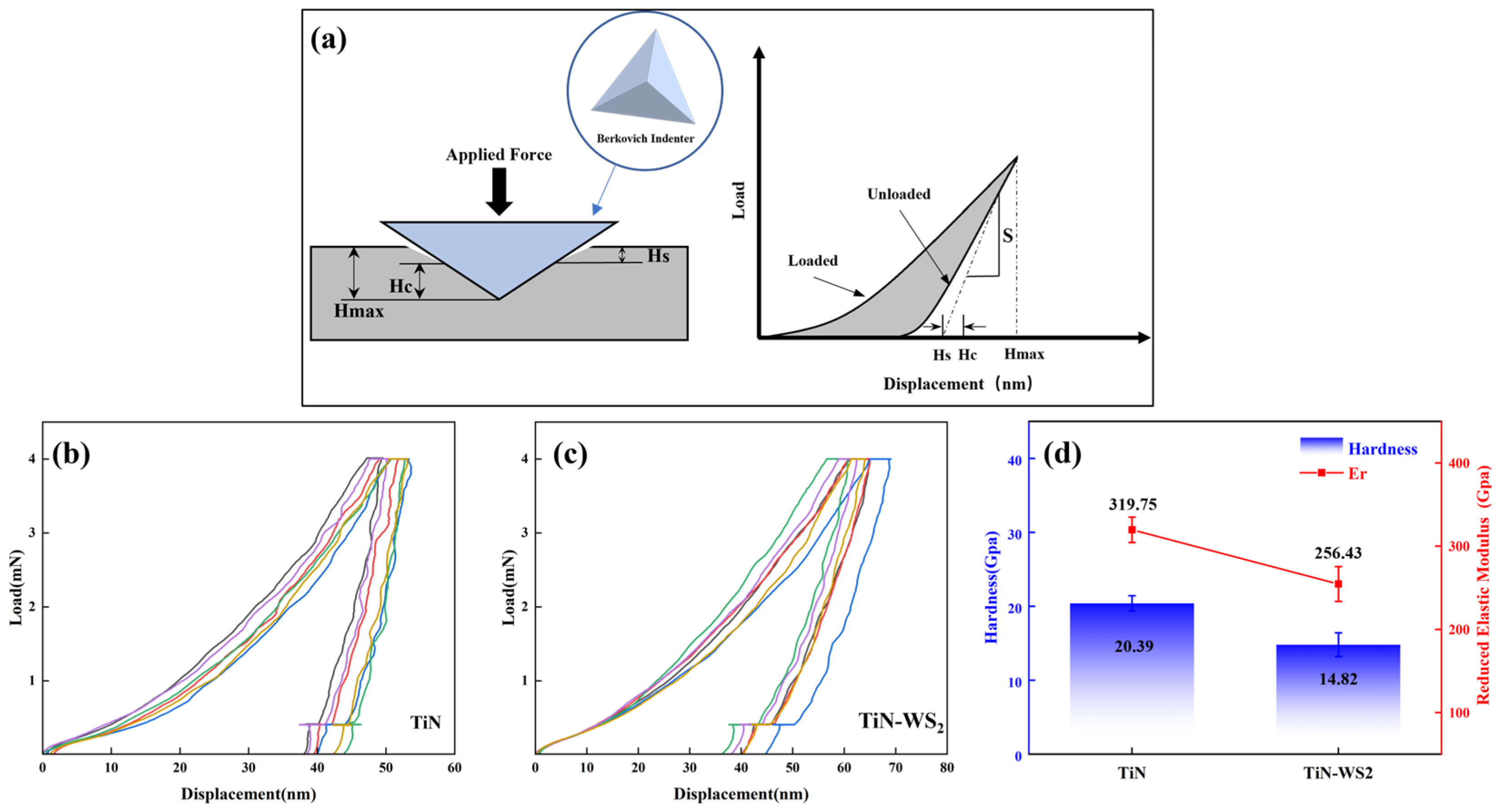
3.2. Hardness Analysis of the Coatings

Figure 4a illustrates the fundamental principle of nanoindentation testing, depicting the loading process of the indenter and the extraction of key evaluation parameters. Figure 4b,c show the load–displacement curves of the TiN and TiN–WS2 coatings under a constant load mode, while Figure 4d summarizes the average hardness and reduced modulus (Er) of both coatings. Nanoindentation tests were conducted using a Nano Indenter G200X (KLA Instruments, Milpitas, CA, USA) equipped with a Berkovich diamond tip under a constant load of 4 mN and a hold period of 2 s. For each coating, six independent indentations were performed at different locations to ensure the statistical reliability and representativeness of the results. The hardness and reduced modulus (Er) values were determined using the Oliver–Pharr method. As Poisson’s ratio of the coatings was not assumed, all the modulus values reported herein refer to the reduced modulus (Er).
The measured average penetration depths were 52 nm for the TiN coating and 64 nm for the TiN–WS2 composite coating; both were well below 10% of their respective coating thicknesses (approximately 1.3 μm for TiN and 660 nm for TiN–WS2). This ensured that the influence of the substrate on the measured mechanical properties was negligible. The G200X instrument was properly calibrated using standard reference samples and was equipped with high-precision displacement and load control systems, guaranteeing the accuracy and stability of the measurements at the nanoscale level.
The results show that the TiN coating exhibited an average hardness of 20.39 ± 1.1 GPa and an Er of 319.75 ± 13 GPa, reflecting its high mechanical strength and dense microstructure. In contrast, the TiN–WS2 composite coating showed a lower hardness of 14.82 ± 1.9 GPa and an Er of 256.43 ± 21 GPa, with greater variation across the test sites. This increased dispersion is likely attributable to the non-uniform distribution of the WS2 phase and the reduced coating compactness.
The measured values for the TiN coating are in good agreement with those reported in the literature for magnetron-sputtered TiN films, where the hardness typically ranges from 18 to 22 GPa and the Er ranges from 300 to 340 GPa [41]. Although systematic mechanical characterizations of magnetron-sputtered TiN–WS2 composite coatings remain limited, the present results fall within the expected range and conform to the widely recognized trend that the incorporation of a soft lubricating phase such as WS2 leads to a decrease in both the hardness and modulus [42].
In summary, although the TiN–WS2 coating exhibited a slightly lower hardness and Er compared to the pure TiN coating, its tribological potential remains promising in engineering applications. The inherent lubricating characteristics of WS2 may enhance interfacial shear behavior, providing a beneficial trade-off between mechanical robustness and frictional performance. However, it should be emphasized that nanoindentation alone cannot directly reveal microstructural features. Therefore, the correlation between the mechanical response and structural mechanisms must be further validated through follow-up friction tests and microstructural characterization. The comprehensive performance of these coatings will be discussed in detail in the subsequent sections.

3.3. Adhesion Strength Evaluation of the Coatings

Scratch testing was conducted under a linearly increasing load mode to evaluate the mechanical integrity and interfacial adhesion strength of the coatings under progressively applied loads. The initial load was set at 30 mN and gradually increased to a maximum of 30 N at a constant loading rate, ensuring a continuous and controllable variation in the applied force during the scratch process. The scratch motion was driven by a computer-controlled stage at a speed of 30 mm/min, with a total scratch length of 150 mm, covering a typical range of service conditions from low to high loads. Throughout the test, an integrated acoustic emission (AE) sensor was used to monitor the failure behavior of the coating in real time. AE signals, which originate from microstructural changes in the material (e.g., crack initiation, propagation, or interfacial delamination), are sensitive indicators of localized failure events under applied loads. In this study, no additional interlayers, such as Ti or Cr, were introduced between the coating and the substrate. This decision was made to evaluate the intrinsic adhesion performance of the TiN and TiN–WS2 coatings when directly deposited on the YG8 cemented carbide substrate. Moreover, avoiding foreign interlayers helped preserve the compositional purity of the coating system and ensured that any observed mechanical behavior originated solely from the TiN and WS2 phases.
Figure 5a illustrates the working principle of the nano-scratch testing system. The specimen was fixed on a movable platform, and a diamond stylus was programmed to move linearly across the sample surface under a progressively increasing normal load. During the scratching process, both the normal load (FnC) and the acoustic emission (AE) signals were simultaneously recorded.
Figure 5b1,c1 display the AE signal intensity and normal load (FnC) as functions of scratch distance for the TiN and TiN–WS2 coatings, respectively. Sudden changes in the AE signal are typically indicative of structural failure initiation or interfacial degradation. The corresponding optical images of the scratch tracks at the failure points are shown in Figure 5b2,c2.
For the TiN coating, a sharp increase in the AE signal occurred at a scratch distance of approximately 11 mm, with a corresponding load of around 21.75 N. At this point, the optical image revealed partial edge damage and minor material removal, indicating the onset of localized failure. For the TiN–WS2 coating, a distinct AE peak was observed at a scratch distance of roughly 9 mm under a load of 19.81 N. Although no significant spallation or full delamination was observed in the optical image, the scratch edge appeared disturbed, with fine discontinuities along the track. These features suggest early-stage interfacial degradation or the development of subsurface microcracks.
Compared to TiN, the TiN–WS2 coating exhibited a slightly lower mechanical stability and weaker adhesion to the substrate under an increasing load. The absence of brittle fractures or large-area delamination may be attributed to the relatively lower hardness of the TiN–WS2 coating, which allowed for plastic deformation rather than catastrophic failure. This response likely reflects the mechanical behavior of the incorporated WS2 phase and its interaction with the TiN matrix, rather than classical brittle decohesion at the interface [43].

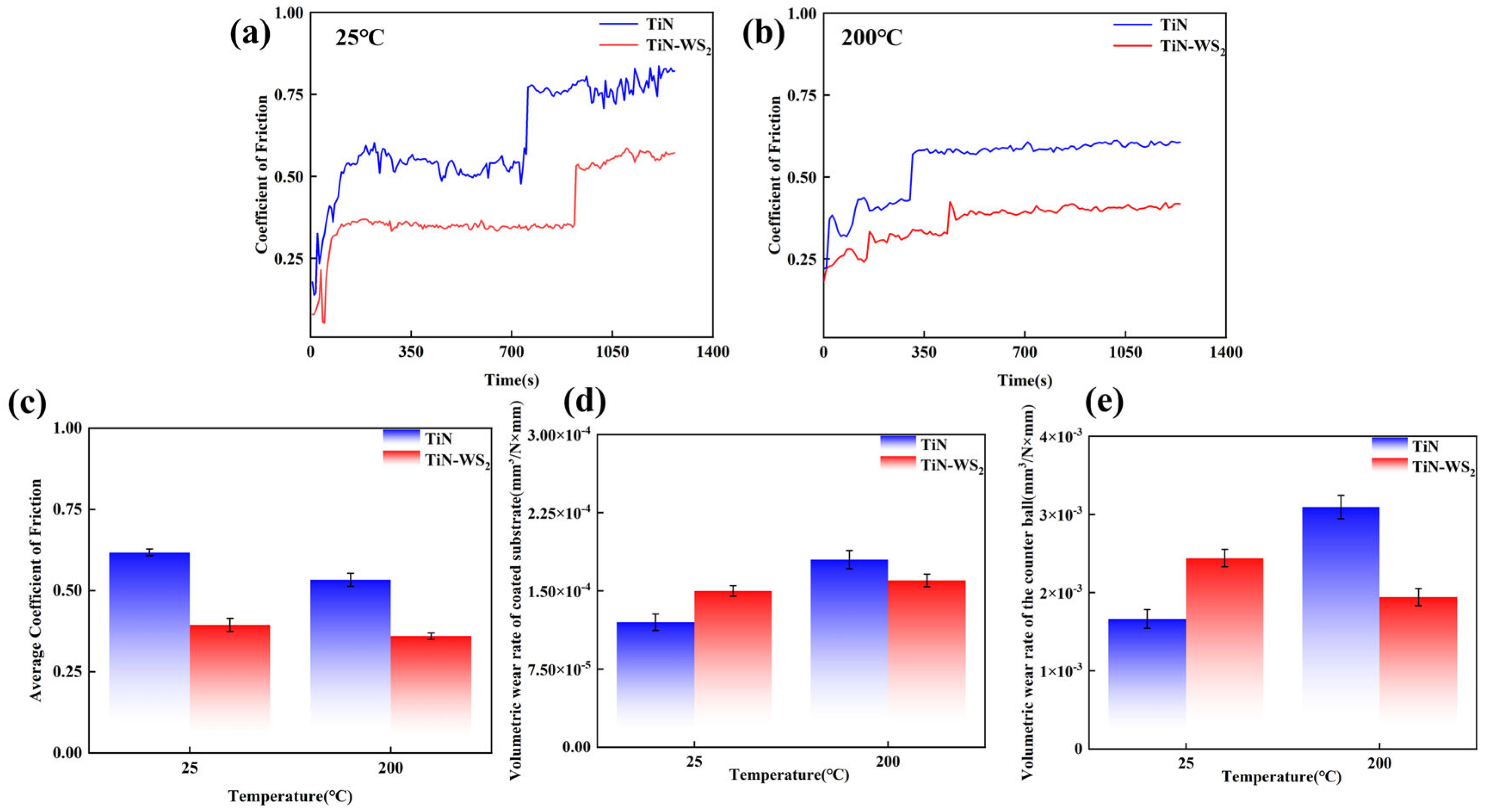
3.4. Tribological Performance and Analysis of the Coatings

Figure 6a,b illustrate the evolution of the coefficient of friction (COF) for TiN and TiN–WS2 coatings under room temperature (25 °C) and an elevated temperature (200 °C). Both coatings exhibited a typical two-stage frictional behavior: Stage I—initial sliding, characterized by a relatively stable COF during the running-in period; and Stage II—coating failure, marked by a sharp increase in the COF due to coating wear-through and the subsequent exposure of the YG8 substrate, which inherently lacks lubricity [42].
To validate the repeatability of the frictional transitions, three replicate tests were conducted under each condition. For the TiN coating, the COF began to increase at approximately 700 ± 30 s at 25 °C, and at around 300 ± 20 s at 200 °C. In comparison, the TiN–WS2 composite coating exhibited delayed transition times of approximately 950 ± 30 s and 450 ± 40 s at the respective temperatures, indicating better wear resistance and confirming the accelerating effect of temperature on coating degradation. The COF increase was primarily attributed to direct contact between the steel ball and the exposed YG8 substrate following wear-through.
Compared to TiN, the TiN–WS2 coating consistently demonstrated a lower and more stable COF across both temperature conditions, with a more gradual and delayed increase post-failure. This trend was especially pronounced at 200 °C, suggesting that the incorporation of WS2 effectively suppresses frictional instability and enhances the high-temperature tribological performance.
Figure 6c further compares the average COFs of the two coatings at both temperatures. At 25 °C, the average COF was 0.61 for the TiN coating and 0.39 for the TiN–WS2 composite coating, corresponding to a reduction of approximately 36%. At 200 °C, the values were 0.53 and 0.36, respectively, with a 32% reduction. These results affirm that the addition of WS2 significantly reduces interfacial friction at both ambient and elevated temperatures, indicating an excellent self-lubricating capability and thermal adaptability.
Figure 6d,e compare the volumetric wear rates of the coated substrates and the corresponding steel balls under two temperature conditions: 25 °C and 200 °C. The results indicate significant differences in both the wear behavior and the temperature sensitivity between the two coatings.
At 25 °C, the TiN-coated substrate exhibited a lower wear rate of 1.24 × 10⁻⁴ mm3/N·mm, compared to 1.57 × 10⁻⁴ mm3/N·mm for the TiN–WS2 composite coating. Similarly, the wear rate of the steel ball was also lower in the TiN-coated pair (1.66 × 10⁻³ mm3/N·mm vs. 2.44 × 10⁻³ mm3/N·mm). This superior wear resistance was primarily attributed to the high hardness and dense microstructure of the TiN coating, which effectively suppressed abrasive wear and plastic deformation [29]. In contrast, although the TiN–WS2 composite coating exhibited a lower coefficient of friction at room temperature, the incorporation of the WS2 lubricating phase may have compromised the overall hardness and compactness of the coating. As a result, it became more susceptible to localized plastic deformation and abrasive particle penetration under contact stress, slightly increasing the wear rates of both the substrate and the counterface.
At 200 °C, the TiN coating showed a higher wear rate for both the substrate (1.83 × 10⁻⁴ mm3/N·mm) and the steel ball (3.09 × 10⁻³ mm3/N·mm), suggesting potential thermal softening, oxidation, and microcrack propagation. In comparison, the TiN–WS2 composite coating exhibited better high-temperature wear resistance, with substrate and ball wear rates of 1.49 × 10⁻⁴ mm3/N·mm and 1.94 × 10⁻³ mm3/N·mm, respectively.
Although the TiN coating presented a higher coefficient of friction at 25 °C, its wear rate remained lower than that of the TiN–WS2 composite, indicating that wear resistance is not solely governed by friction levels. This “high-friction–low-wear” behavior is mainly attributed to the inherent hardness and compact structure of the TiN coating, which enhances resistance to abrasive and plastic damage. A similar trend was reported by Jakab et al. (2023) in their study on TiN/TiC CVD coatings, where a higher friction coefficient did not necessarily result in a higher wear rate, thereby supporting the view that there is no simple linear relationship between friction and wear [44].
At 200 °C, the TiN coating exhibited a significantly increased wear rate, whereas the TiN–WS2 composite coating showed a lower wear rate and a more stable friction coefficient, demonstrating an excellent tribological performance at elevated temperatures. This performance discrepancy suggests that, as the temperature increases, the dominant wear mechanism may undergo a transition from mechanically driven abrasive wear dominated by hard-phase reinforcement to thermally activated lubrication characterized by the formation of lubricating films. A similar trend was reported by Liu et al. (2020), who investigated the wear behaviors of TiN/WS2 + hBN/NiCrBSi self-lubricating composite coatings and found that, during sliding friction, the lubricating phases, WS2 and the in situ formed TiS contributed to the formation of a lubricating transfer film on the worn surface, This effectively reduced the friction coefficient and enhanced the wear resistance, thereby validating the temperature-induced shift in wear mechanism dominance toward lubrication control [42].

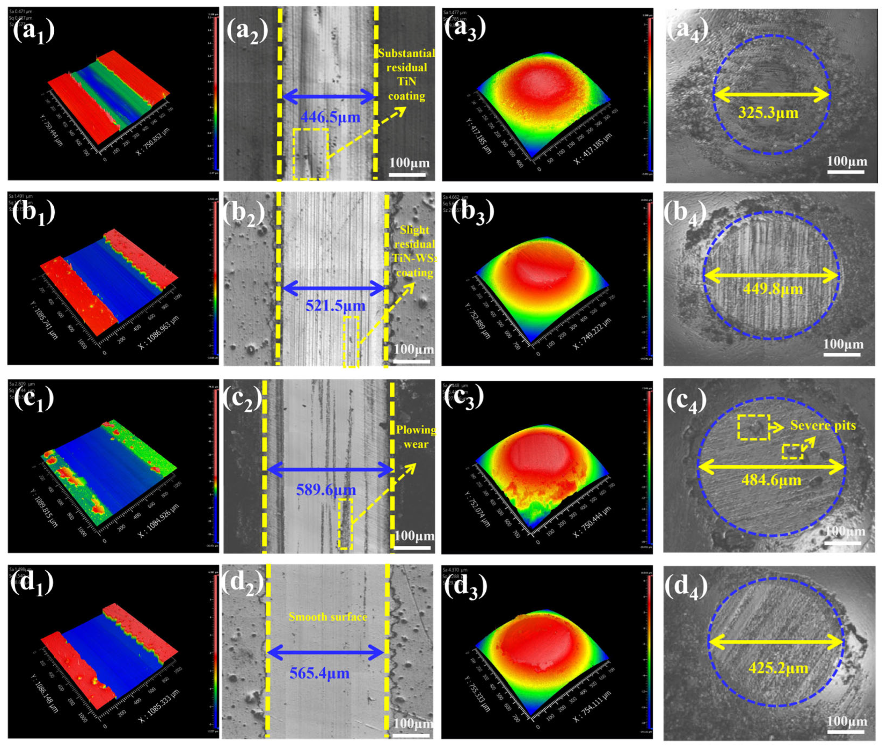
3.5. Post-Test Wear Track Analysis of Ball-on-Disk Tribological Tests

Figure 7 compares the wear behavior of pure TiN and TiN–WS2 composite coatings in ball-on-disk tribological tests, characterized by three-dimensional surface topography using white light interferometry.
At room temperature (25 °C), the TiN coating exhibited continuous furrow-like wear features on the disk surface (Figure 7(a1,a2)), with a narrow and elongated wear track of approximately 446.5 μm in width, indicating typical abrasive wear [45]. Notably, a substantial portion of the TiN coating remained within the wear track region, as revealed by the optical image in Figure 7(a2). The corresponding wear scar on the counterface ball (Figure 7(a3,a4)) had a diameter of 325.3 μm, showing a pronounced concave wear zone. The surface exhibited a poor smoothness, with evidence of abrasive interaction and minor adhesive wear, as confirmed by the presence of pit-like damage [45]. In comparison, the TiN–WS2 composite coating (Figure 7(b1,b2)) showed a slightly wider wear track of 521.5 μm on the disk and an enlarged wear scar of 449.8 μm on the ball. Although the wear track contained only a slight residual coating, some surface spalling and micropore formation were observed, likely due to the lower hardness of the composite. This reduced hardness made the coating more susceptible to plastic deformation and material removal during sliding. Although the composite coating achieved a lower coefficient of friction, its wear rate at room temperature was slightly higher than that of the TiN coating.
At 200 °C, the difference in wear behavior between the two coatings became more pronounced. The TiN coating (Figure 7(c2,c4)) exhibited a significantly widened wear track of 589.6 μm and an expanded ball scar diameter of 484.6 μm. The worn surface displayed severe plowing and adhesive damage, with no significant residual coating observed within the wear track, indicating that the TiN coating had experienced full wear-through under elevated thermal and mechanical stress. In contrast, the TiN–WS2 composite coating (Figure 7(d2,d4)) exhibited a slightly narrower wear track (565.4 μm) and a smaller ball scar (425.2 μm). The worn surface appeared relatively smooth and continuous, with no deep grooves or evidence of large-area delamination. The residual surface integrity was maintained, indicating better wear resistance and interfacial stability under elevated temperature conditions.
In summary, although the TiN–WS2 composite coating showed a slightly higher wear rate than TiN at room temperature, it demonstrated better wear resistance and more moderate surface damage under high-temperature conditions. These results confirm that the incorporation of WS2 significantly enhances the anti-wear performance and surface integrity of the coating in thermally demanding tribological environments.

4. Conclusions

In this study, TiN and TiN–WS2 composite coatings were successfully deposited on cemented carbide substrates using magnetron co-sputtering. By adjusting the power ratio between the Ti and WS2 targets, the synergistic incorporation of the hard phase and lubricating phase was achieved within the coating. A comprehensive performance characterization—including nanoindentation, scratch adhesion testing, reciprocating tribological experiments, and 3D white light interferometry—was conducted to evaluate the mechanical and tribological behaviors of the coatings under both room and elevated temperature conditions. The main conclusions are as follows:
(i) TiN and TiN–WS2 composite coatings were successfully prepared via magnetron co-sputtering. The incorporation of WS2 modified the coating’s microstructure and tribological behavior to a certain extent.
(ii) The nanoindentation results indicated that the TiN coating exhibited an average hardness of 20.39 GPa and a reduced elastic modulus (Er) of 319.75 GPa, reflecting its high mechanical strength and dense microstructure. In contrast, the TiN–WS2 composite coating showed a lower hardness of 14.82 GPa and an Er of 256.43 GPa, corresponding to reductions of approximately 27.3% and 19.8%, respectively. This significant decrease suggests that, although the incorporation of WS2 imparts lubricating functionality to the coating, it also compromises the overall stiffness and load-bearing capacity of the film.
(iii) The scratch test results revealed that the TiN coating exhibited a critical AE signal spike at around 11 mm (FnC ≈ 21.5 N), indicating interfacial failure. The TiN–WS2 composite coating showed failure at approximately 9 mm (FnC ≈ 19.81 N), accompanied by coating edge delamination and peeling. Although the composite exhibited a slightly lower structural stability and interfacial strength under a high load, it still maintained an acceptable adhesion performance.
(iv) In reciprocating friction tests at both room temperature (25 °C) and an elevated temperature (200 °C), the TiN–WS2 composite coating consistently exhibited a lower coefficient of friction than the TiN coating. At 25 °C, the COF decreased from 0.61 to 0.39 (a 36% reduction), and at 200 °C, it decreased from 0.53 to 0.36 (a 32% reduction).
(v) The wear rate and white light interferometry analyses indicated that the TiN–WS2 coating showed a slightly higher wear rate than TiN at room temperature (1.57 × 10⁻⁴ mm3/N·mm vs. 1.24 × 10⁻⁴ mm3/N·mm), but outperformed TiN under high-temperature conditions (1.49 × 10⁻⁴ mm3/N·mm vs. 1.83 × 10⁻⁴ mm3/N·mm), demonstrating a superior wear resistance and surface stability at elevated temperatures.
This study further explored the mechanisms by which the lubricating phase WS2 influenced the evolution of the TiN-based coating performance. Although the incorporation of WS2 via co-sputtering resulted in a moderate reduction in hardness and interfacial adhesion strength, it significantly reduced the coefficient of friction while maintaining structural integrity. This effect was particularly pronounced under high-temperature conditions. Compared to conventional TiN coatings, the TiN–WS2 composite coating demonstrated a more favorable combination of friction-reducing and wear-resistant properties, highlighting its promising potential for applications in complex thermo-tribological environments.

Author Contributions

Conceptualization, H.Q. and Y.W.; data curation, S.Z.; funding acquisition, H.Q. and J.Y.; investigation, Y.W., J.Y., S.F. and J.K.; methodology, Y.W. and S.Z.; software, P.T. and S.F.; writing—original draft, S.Z.; writing—review and editing, Y.W. All authors have read and agreed to the published version of the manuscript.

Funding

This work was financially supported by the Innovation Capability Support Program of Shaanxi (No. 2024CX-GXPT-21), the Key R & D plan of Shaanxi Province (No. 2023-YBGY-097), and the Shaanxi Science and Technology Resources Open Sharing Platform (No. 2022PT-02).

Institutional Review Board Statement

Not applicable.

Informed Consent Statement

Not applicable.

Data Availability Statement

The data are contained within the article.

Conflicts of Interest

Author Jianxin Yang was employed by the company Information Center of China North Industries Group Corporation. The remaining authors declare that the research was conducted in the absence of any commercial or financial relationships that could be construed as a potential conflict of interest.

References

  1. Zhang, J.J.; Zhang, G.Q.; Fan, G.H. Effects of tool coating materials and coating thickness on cutting temperature distribution with coated tools. Int. J. Appl. Ceram. Technol. 2022, 19, 2276–2284. [Google Scholar] [CrossRef]
  2. Mahesh, L.; Vinyas, M.; Reddy, J.S.; Muralidhara, B.K. Investigation of the microstructure and wear behaviour of titanium compounds reinforced aluminium metal matrix composites. Mater. Res. Express 2019, 6, 026516. [Google Scholar] [CrossRef]
  3. Ye, F.X.; Zhao, H.J.; Tian, X.B. The elevated-temperature wear properties of TiN and TiN/W2N coatings. Mater. Res. Express 2018, 5, 106404. [Google Scholar] [CrossRef]
  4. da Silva, F.C.; Macedo, M.D.; Miscione, J.M.C.; Fontana, L.C.; Sagás, J.C.; Cozza, R.C.; Schön, C.G. Use of ball-cratering wear test and nanoscratching test to compare the wear resistance of homogeneous and functionally graded titanium nitride thin films. J. Mater. Res. Technol. 2023, 22, 54–65. [Google Scholar] [CrossRef]
  5. Cheng, P.; DelaCruz, S.; Tsai, D.S.; Wang, Z.T.; Carraro, C.; Maboudian, R. Enhanced thermal stability by introducing TiN diffusion barrier layer between W and SiC. J. Am. Ceram. Soc. 2019, 102, 5613–5619. [Google Scholar] [CrossRef]
  6. Carabillò, A.; Sordetti, F.; Querini, M.; Magnan, M.; Azzolini, O.; Fedrizzi, L.; Lanzutti, A. Tribological optimization of titanium-based PVD multilayer hard coatings deposited on steels used for cold rolling applications. Mater. Today Commun. 2023, 34, 105043. [Google Scholar] [CrossRef]
  7. Lozovan, A.; Savushkina, S.; Lyakhovetsky, M.; Nikolaev, I.; Betsofen, S.; Kubatina, E. Investigation of Structural and Tribological Characteristics of TiN Composite Ceramic Coatings with Pb Additives. Coatings 2023, 13, 1463. [Google Scholar] [CrossRef]
  8. Intanon, N.; Wisitsoraat, A.; Saikaew, C. An application of statistical quality tools for process robustness and sustainability of titanium nitride coating on a machine component of a fishing net weaving machine. J. Clean. Prod. 2022, 363, 132603. [Google Scholar] [CrossRef]
  9. Liu, G.; Liao, T.C.; Wang, S.Z.; Li, Y.Q.; Guo, H.B.; Wu, H.H.; Huang, Y.H.; Yong, Q.L.; Mao, X.P. Revealing the precipitation kinetics of multi-stage and multi-scale Ti-bearing precipitation in a 460 MPa grade HSLA steel. Mater. Sci. Eng. A-Struct. Mater. Prop. Microstruct. Process. 2024, 890, 145941. [Google Scholar] [CrossRef]
  10. Li, Z.H.; Liu, L.; You, X.; Yi, J.H.; Bao, R.; Zhu, M.Y.; Lu, S.; Pai, J.J. Cooperative enhancement of mechanical and tribological properties through tailoring TiN transition interface in boron nitride nanosheets reinforced copper composites. Rare Met. 2024, 43, 5202–5215. [Google Scholar] [CrossRef]
  11. Kupczyk, M.; Lelen, M.; Józwik, J.; Tomilo, P. Modeling Material Machining Conditions with Gear-Shaper Cutters with TiN0.85-Ti in Adhesive Wear Dominance Using Machine Learning Methods. Materials 2024, 17, 5567. [Google Scholar] [CrossRef]
  12. Zuo, B.; Yu, L.H.; Xu, J.H. Effect of Ag content on friction and wear properties of TiCN/Ag films in different service environments. Vacuum 2023, 212, 112029. [Google Scholar] [CrossRef]
  13. Ye, T.C.; Le, K.; Wang, G.G.; Ren, Z.H.; Liu, Y.Z.; Zheng, L.W.; Tian, H.; Xu, S.S. Structure Modulation and Self-Lubricating Properties of Porous TiN-MoS2 Composite Coating Under Humidity-Fluctuating Conditions. Lubricants 2025, 13, 61. [Google Scholar] [CrossRef]
  14. Ronadson, B.J.; Vijayan, K.; Sanmugam, S.; Badhirappan, G.P. Improving dry machining performance of surface modified cutting tools through combined effect of texture and TiN-WS2 coating. J. Manuf. Process. 2023, 85, 101–108. [Google Scholar] [CrossRef]
  15. Rajakumar, N.; Subramanian, K.; Sozhan, G.; Ramasamy, K. Tribological studies of the sintered bronze-tungsten disulfide composites. Mater. Res. Express 2019, 6, 086568. [Google Scholar] [CrossRef]
  16. Wang, J.; Zhou, R.Z.; Zhang, D.G.; Wang, Z.R.; Gu, X.L.; Wang, H. Enhancing tribological properties of carbon-based films through catalytic Ni3C. Diam. Relat. Mater. 2024, 144, 110957. [Google Scholar] [CrossRef]
  17. Vadivelmurugan, A.; Anbazhagan, R.; Lai, J.Y.; Tsai, H.C. Paramagnetic properties of manganese chelated on glutathione-exfoliated MoS2. Colloids Surf. A-Physicochem. Eng. Asp. 2021, 608, 125432. [Google Scholar] [CrossRef]
  18. Li, Q.; Zheng, S.X.; Pu, J.B.; Wang, W.Z.; Li, L.; Wang, L.P. Revealing the failure mechanism and designing protection approach for MoS2 in humid environment by first-principles investigation. Appl. Surf. Sci. 2019, 487, 1121–1130. [Google Scholar] [CrossRef]
  19. Dam, A.T.; Le, L.T.; Tran, P.D. Electrochemical unzipping of multiple-walled WS2 nanotubes for synthesis of WS2 nanoribbons being an attractive H2 evolution catalyst. Mater. Lett. 2024, 377, 137415. [Google Scholar] [CrossRef]
  20. Liu, J.; Yan, Z.; Hao, J.Y.; Liu, W.M. Two strategies to improve the lubricating performance of WS2 film for space application. Tribol. Int. 2022, 175, 107825. [Google Scholar] [CrossRef]
  21. Yan, Z.; Zhou, H.B.; Zhang, X.; Liu, J.; Wang, C.; Lu, X.L.; Hao, J.Y.; Sui, X.D. Interactive effect between WS2 films with different structures and space oils for improvement of tribological performance. Tribol. Int. 2022, 170, 107431. [Google Scholar] [CrossRef]
  22. Liang, D.W.; Zhang, C.; Shen, C.Y.; Cao, G.T.; Liao, N.B.; Zhang, M. First-Principles Study of Superlubricity of Two-Dimensional Graphene/ WS2 Heterostructures. Tribol. Lett. 2025, 73, 12. [Google Scholar] [CrossRef]
  23. Tian, J.Y.; Lu, K.; Liu, X.J. Hybrid heterostructure of transition metal dichalcogenides as potential photocatalyst for hydrogen evolution. Appl. Surf. Sci. 2022, 599, 154057. [Google Scholar] [CrossRef]
  24. Lu, Z.X.; Zhang, C.Z.; Zeng, C.; Ren, S.M.; Pu, J.B. A novel design by constructing MoS2/WS2 multilayer film doped with tantalum toward superior friction performance in multiple environment. J. Mater. Sci. 2021, 56, 17615–17631. [Google Scholar] [CrossRef]
  25. Asgary, S.; Ramezani, A.H.; Nejad, Z.E. Characterization of high quality, monolayer WS2 domains via chemical vapor deposition technique. Appl. Phys. A-Mater. Sci. Process. 2022, 128, 139. [Google Scholar] [CrossRef]
  26. Kim, S.J.; Luo, D.; Park, K.; Choe, M.; Kim, D.W.; Wang, M.; Jung, W.B.; Lee, Z.; Ruoff, R.S.; Jung, H.T. Mapping Graphene Grain Orientation by the Growth of WS2 Films with Oriented Cracks. Chem. Mater. 2020, 32, 7484–7491. [Google Scholar] [CrossRef]
  27. Bouska, M.; Nazabal, V.; Gutwirth, J.; Halenkovic, T.; Nemec, P. Radio-frequency magnetron co-sputtered Ge-Sb-Te phase change thin films. J. Non-Cryst. Solids 2021, 569, 121003. [Google Scholar] [CrossRef]
  28. Ren, Z.Y.; Chen, L.P.; Liu, X.M.; Li, G.J.; Wang, K.; Wang, Q. Preparation, characterization and simulation of Al@SiO2 nanoparticle composite films with infrared-visible stealth. Infrared Phys. Technol. 2020, 111, 103472. [Google Scholar] [CrossRef]
  29. Zhou, Q.; Ou, Y.X.; Li, F.Q.; Ou, C.Y.; Xue, W.B.; Liao, B.; Hua, Q.S.; Xu, Y.F.; Cao, J.D.; Qu, G.S. Friction and Wear of Hard Yet Tough TiN Coatings Deposited Using High-Power Impulse Magnetron Sputtering. Coatings 2024, 14, 598. [Google Scholar] [CrossRef]
  30. Cristea, D.; Velicu, I.L.; Cunha, L.; Barradas, N.; Alves, E.; Craciun, V. Tantalum-Titanium Oxynitride Thin Films Deposited by DC Reactive Magnetron Co-Sputtering: Mechanical, Optical, and Electrical Characterization. Coatings 2022, 12, 36. [Google Scholar] [CrossRef]
  31. Sun, Y.L.; Nabatame, T.; Chung, J.W.; Sawada, T.; Miura, H.; Miyamoto, M.; Tsukagoshi, K. Compositional changes between metastable SnO and stable SnO2 in a sputtered film for p-type thin-film transistors. Thin Solid Film. 2024, 807, 140548. [Google Scholar] [CrossRef]
  32. Gardella, M.; Zambito, G.; Ferrando, G.; Barusso, L.F.; Chennuboina, R.; Repetto, L.; Barelli, M.; Giordano, M.C.; de Mongeot, F.B. Maskless Synthesis of van der Waals Heterostructure Arrays Engineered for Light Harvesting on Large Area Templates. Small 2025, 21, e2400943. [Google Scholar] [CrossRef]
  33. Deng, W.H.; Wang, J.; Yang, M.; Li, G.; Xiong, Q.L.; Yin, Y.J. Effect of Brazing Temperature on Microstructure and Mechanical Properties of YG8/IN718 Joints. Trans. Indian Inst. Met. 2023, 76, 3253–3261. [Google Scholar] [CrossRef]
  34. Zhang, Y.H.; Song, W.B.; Ji, H.Z. Study on Friction Reduction and Wear Resistance of Surface Micro-texture of YG8-Ti6Al4V Friction Pair. Integr. Ferroelectr. 2021, 218, 225–238. [Google Scholar] [CrossRef]
  35. Xiang, Y.T.; Xiong, J.; Xiang, Q.Z.; Guo, Z.X.; Li, L.S.; Chen, Y.F. Effect of Cr ion etching on the structure and properties of TiAlN-coated cemented carbide. Int. J. Refract. Met. Hard Mater. 2023, 116, 106357. [Google Scholar] [CrossRef]
  36. De Maio, D.; D’Alessandro, C.; Caldarelli, A.; De Luca, D.; Di Gennaro, E.; Casalino, M.; Iodice, M.; Gioffre, M.; Russo, R.; Musto, M. Multilayers for efficient thermal energy conversion in high vacuum flat solar thermal panels. Thin Solid Film. 2021, 735, 138869. [Google Scholar] [CrossRef]
  37. Changyom, P.; Leksakul, K.; Charoenchai, N.; Boonyawan, D. Designed and Produced the Rotary Substrate Holder and Its Optimized in Angular DC Magnetron Co- Sputtering System. Chiang Mai J. Sci. 2022, 49, 1633–1643. [Google Scholar] [CrossRef]
  38. Qiao, H.; Liu, M.H.; Xiang, Y.; Xu, X.L.; Wang, Z.; Wu, W.X.; Wang, Y.Q. Low-Friction Coatings Grown on Cemented Carbides by Modulating the Sputtering Process Parameters of TiN Targets. Coatings 2025, 15, 329. [Google Scholar] [CrossRef]
  39. Abd El-Fattah, H.A.; El-Mahallawi, I.S.; Shazly, M.H.; Khalifa, W.A. Optical Properties and Microstructure of TiNxOy and TiN Thin Films before and after Annealing at Different Conditions. Coatings 2019, 9, 22. [Google Scholar] [CrossRef]
  40. Ito, S.; Teraoka, K.; Imai, S.; Matsunaga, N.; Jang, J.; Muneta, I.; Kakushima, K.; Wakabayashi, H. Crystallinity improvement of physical-vapor-deposited WS2 films by controlling particle energy. Jpn. J. Appl. Phys. 2025, 64, 02sp08. [Google Scholar] [CrossRef]
  41. Ma, B.; Yuan, H.; He, Z.; Shang, H.; Hou, Y.; Ju, H.; Fernandes, F. Microstructure and Mechanical Properties of Magnetron Sputtering TiN-Ni Nanocrystalline Composite Films. Coatings 2023, 13, 1902. [Google Scholar] [CrossRef]
  42. Liu, K.; Yan, H.; Zhang, P.; Zhao, J.; Yu, Z.; Lu, Q. Wear Behaviors of TiN/WS2 + hBN/NiCrBSi Self-Lubricating Composite Coatings on TC4 Alloy by Laser Cladding. Coatings 2020, 10, 747. [Google Scholar] [CrossRef]
  43. Zhang, Z.; Qin, X.; Ma, S.; Liu, Y.; Wang, L.; Zhao, X. Synergistic Effect of WS2 and Micro-Textures to Inhibit Graphitization and Delamination of Micro-Nano Diamond-Coated Tools. Crystals 2023, 13, 1034. [Google Scholar] [CrossRef]
  44. Jakab, M.; Ali, O.I.; Gyurika, I.G.; Korim, T.; Telegdi, J. The Tribological Behavior of TiN/TiC CVD Coatings under Dry Sliding Conditions against Zirconia and Steel Counterparts. Coatings 2023, 13, 832. [Google Scholar] [CrossRef]
  45. Zhao, Z.L.; Li, Y.F.; Li, Y.L.; Zheng, Q.L. Effect of Ti and TiN inter-layers on the composite interfacial wettability and composite abrasive wear resistance. Tribol. Int. 2025, 207, 110615. [Google Scholar] [CrossRef]
Figure 1. Schematic illustration of the reactive principle of magnetron sputtering.
Coatings 15 00596 g001
Figure 2. Surface and structural characterization of TiN and TiN–WS2 composite coatings: (a) macroscopic surface morphology of coatings deposited on YG8 cemented carbide substrates; (b) X-ray diffraction (XRD) patterns of coatings deposited on silicon wafers, showing prominent (111), (200), (220), and (311) peaks in the TiN coating, indicative of a high crystallinity, while the TiN–WS2 composite coating exhibited significantly reduced diffraction intensities; (c) cross-sectional SEM image of the TiN coating deposited on a silicon wafer; and (d) cross-sectional SEM image of the TiN–WS2 composite coating deposited on a silicon wafer.
Coatings 15 00596 g002
Figure 3. Surface morphology and elemental distribution of TiN and TiN–WS2 composite coatings: (a1,a2) surface SEM images of the TiN coating at magnifications of 1 μm and 200 nm, respectively; (a3) EDS elemental mapping and atomic percentage analysis of the TiN coating; (b1,b2) surface SEM images of the TiN–WS2 composite coating at magnifications of 1 μm and 200 nm, respectively; and (b3) EDS elemental mapping and atomic percentage analysis of the TiN–WS2 composite coating.
Coatings 15 00596 g003
Figure 4. Schematic diagram of nanoindentation testing, load–displacement curves, and comparison of mechanical properties of the coatings: (a) schematic illustration of the nanoindentation process and key evaluation parameters; (b) load–displacement curve of the TiN coating; (c) load–displacement curve of the TiN–WS2 composite coating; (d) comparison of average hardness and reduced modulus (Er) of the two coatings.
Coatings 15 00596 g004
Figure 5. Nano-scratch testing results: (a) Schematic diagram of the nano-scratch testing system; (b1) AE signal and normal load (FnC) variation curves recorded during the scratch test of the TiN coating; (b2) optical image and magnified detail of the corresponding scratch track on the TiN coating; (c1) AE signal and normal load (FnC) variation curves recorded during the scratch test of the TiN–WS2 composite coating; and (c2) optical image and magnified detail of the corresponding scratch track on the TiN–WS2 composite coating.
Coatings 15 00596 g005
Figure 6. Comparison of the tribological performance of TiN and TiN–WS2 composite coatings under different temperature conditions: (a) coefficient of friction (COF) vs. time at room temperature (25 °C); (b) COF vs. time at an elevated temperature (200 °C); (c) average coefficient of friction at different temperatures; (d) volumetric wear rate of the coated substrates at different temperatures; and (e) volumetric wear rate of the counterpart balls at different temperatures.
Coatings 15 00596 g006
Figure 7. Three-dimensional wear scar topographies, wear track width, and ball scar diameter for TiN and TiN–WS2 coatings under different temperature conditions: (a1a4) TiN coating at room temperature (25 °C); (b1b4) TiN–WS2 composite coating at room temperature (25 °C); (c1c4) TiN coating at an elevated temperature (200 °C); and (d1d4) TiN–WS2 composite coating at an elevated temperature (200 °C).
Coatings 15 00596 g007
Table 1. Experimental substrate material parameters.
SubstrateAmountDimensions (mm)Serve as
YG82Φ 20 × 2.5Mechanical performance test (Ra ≈ 0.025 μm).
Si (111)210 × 10 × 0.5Microscopic morphology, physical phase testing, etc.
Table 2. Sputtering parameters of TiN and TiN-WS2 coatings.
No.12
Coating MaterialTiNTiN-WS2
Target MaterialTiNTiNWS2
Power Supply TypeRFDCRF
Sputtering Power (W)150150120
Working Pressure (Pa)0.50.5
Deposition Time (min)180180
Deposition Temperature (°C)100100
Substrate Rotation Speed (rpm)010
Working GasArAr
Gas Flow Rate (sccm)2020
Substrate Bias Voltage (V)−50−50
Disclaimer/Publisher’s Note: The statements, opinions and data contained in all publications are solely those of the individual author(s) and contributor(s) and not of MDPI and/or the editor(s). MDPI and/or the editor(s) disclaim responsibility for any injury to people or property resulting from any ideas, methods, instructions or products referred to in the content.

