Review

Modern Innovations and Applications in Plasma Electrolytic Oxidation Coatings on Aluminum, Magnesium, and Titanium

by
Angus G. McCarroll
* and
Pradeep L. Menezes
Department of Mechanical Engineering, University of Nevada, Reno, NV 89557, USA
*
Author to whom correspondence should be addressed.
Coatings 2025, 15(5), 592; https://doi.org/10.3390/coatings15050592
Submission received: 24 March 2025 / Revised: 12 May 2025 / Accepted: 15 May 2025 / Published: 16 May 2025

Abstract

:
Plasma electrolytic oxidation (PEO) is an electrochemical surface modification technique for producing dense oxide layers on valve metals. This review compiles the various modifications to the PEO process that have been used to improve the produced coatings and make them suitable for specific applications, with a focus on examples of aluminum, magnesium, and titanium substrates. An overview of the PEO process is given, highlighting the various process parameters and their effects on the final surface. The challenges with light metals that motivate the use of surface modifications are summarized, along with some of the other modifications that attempt to overcome them. Two broad categories of modifications to the PEO process are presented: in situ modifications, influencing the properties of the coating during its formation, and ex situ modifications, augmenting the properties of an already-formed coating. Finally, specific examples of applications for modified PEO processes are discussed, including battery, biomedical, water treatment, and energy production applications.

Graphical Abstract

1. Introduction

The twentieth century witnessed the widespread adoption of light metal alloys, particularly those based on aluminum, magnesium, and titanium. The high strength and low density of these metals makes them especially useful in the automotive and aerospace industries [1]. However, these metals can also present challenges due to their unique properties. Magnesium, the lightest commonly used engineering metal, has extremely poor corrosion resistance and cannot be protected using a sacrificial anode due to the lack of materials with a more negative equilibrium potential [1,2]. It has been calculated that if all aluminum components in a Boeing 747 could be replaced with magnesium, the weight of the aircraft could be reduced by 60.4 metric tons [3]. However, magnesium’s flammability and susceptibility to corrosion have led to restrictions being placed on its use in aircraft, largely relegating the metal to engine casings and landing gear, with aluminum alloys continuing to dominate in structural components [4]. Magnesium has been more successful in the automotive industry, where pressure to improve fuel economy and performance has led to the use of the metal in a wide range of components, including wheels, seat frames, engine and transmission casings, and chassis components [5]. While the automotive applications of magnesium alloys are diverse, the challenges associated with magnesium, both due to its inherent properties (poor corrosion resistance and difficulty in forming sheet metal components) and broader economic factors (high cost and lack of industry experience compared to steel), mean that magnesium still represents a minuscule fraction of the metals used in the automotive industry [4,5]. The potential uses of magnesium go far beyond the transportation sector. Many current load-bearing medical implants are made from metals such as titanium, steel, and cobalt-chromium alloy. The use of these materials can cause stress shielding, in which bone density is lost due to implants reducing the growth-stimulating loads experienced by the bone, as well as leaching toxic particles into the body by corrosion and wear. Magnesium has the potential to alleviate both problems. It has a density and modulus of elasticity that are closer to human bone than those of commonly used implant metals are, reducing the potential for stress shielding. It is also naturally highly abundant in the human body, being used for many purposes including bone growth. The ability of the body to efficiently excrete excess magnesium lowers the possibility of toxic effects from magnesium accumulation. Nevertheless, magnesium’s chemical properties once again limit its real-world applications. The first magnesium implant, a plate used to set a broken leg in 1907, disintegrated within 8 days of surgery and produced large amounts of gas under the skin [6]. The release of magnesium ions and corrosion products can lead to alkalinization in the vicinity of pure magnesium implants, causing tissue inflammation and encapsulation of the implant [7]. While the controlled biodegradation of medical implants would allow patients to avoid the risks associated with procedures to remove implants, the corrosion of the implant must be slow enough to allow the bone to heal [6,8].
Unlike alloys of magnesium, alloys of titanium can form a passive oxide layer on their surfaces, protecting them from corrosion [9,10,11]. Titanium has better corrosion resistance than stainless steel and better biocompatibility than either stainless steel or cobalt alloy, making it a popular choice for medical implants [10,11,12]. Solid titanium can still cause stress shielding due to its high modulus of elasticity compared to bone, but this can be addressed using porous titanium, which encourages better bone ingrowth and allows the modulus of elasticity to be adjusted. However, increasing the porosity of titanium can also hinder the formation of the passive oxide layer and reduce the strength of the implant [12]. While titanium generally has excellent corrosion resistance due to its passive oxide layer, it is also a highly reactive element in its pure form and remains vulnerable to corrosion when the oxide layer is disturbed [9,10,12]. In tribological systems, the oxide layer is quickly destroyed, and the titanium substrate is exposed. The reactivity of the titanium substrate means it tends to adhere to the counterface, causing rapid wear. Galvanic corrosion is a common problem when titanium is mated to a different metallic surface [13], while cold welding can occur when titanium is mated with itself [14]. Many metals undergo a form of wear known as galling, in which adhesion between surfaces causes macroscopic protrusions to form, increasing friction and potentially causing systems to seize [15,16]. Galling generally does not occur in titanium. Instead, adhesion causes titanium to form flat platelets that break off from the substrate and transfer to the mating surface. Rather than seizing, titanium rapidly wears away, leading to issues such as stripping of threads and screw heads. This is a problem for titanium fasteners that may need to be replaced more often than steel but can also lead to more expensive components being rendered useless due to tapped holes wearing out [16,17]. Large-scale relative motion is not necessary for titanium to wear; microscopic movements such as those caused by vibrations can also cause a large amount of fretting damage to titanium components unless a suitable counterface, such as Stellite 6B, is used [16].
Like titanium, aluminum is a light metal that tends to form a passive protective layer when it oxidizes [1]. Although not as strong as titanium or as light as magnesium, aluminum’s good balance of manufacturability, strength, density, toughness, conductivity, appearance, recyclability, and corrosion resistance have made it a much more popular choice than either metal for engineering purposes [1,4,18,19]. Thanks to the widespread adoption of aluminum since the 1960s, a mature industry exists for aluminum that has reduced both costs and environmental impacts compared to magnesium or titanium [1,20,21,22,23]. However, like magnesium and titanium, aluminum tends to be rather soft, resulting in poor tribological properties [24,25,26]. In tribosystems, aluminum faces a similar problem to titanium wherein wear depassivates the surface, resulting in poor resistance to tribocorrosion despite good corrosion resistance in general [24]. The softness of aluminum also limits its use in applications with high surface loads [18,19].
The issues with light metal alloys have necessitated the development of a variety of surface treatment techniques such as anodizing, vapor deposition, thermal spraying, and organic and inorganic coatings [27]. Like the substrates to which they are applied, these treatments can come with substantial drawbacks. Anodizing, in which protective oxide layers are produced electrochemically, uses large quantities of strong acids, most commonly sulfuric acid, and produces large amounts of waste that are generally disposed of in landfills and sewers, risking the leaching of toxic metals such as chromium and lead into the environment [28,29]. While magnesium can be anodized, the coating’s protective properties are limited by its porosity and the softness of the substrate, like with naturally occurring magnesium oxide layers. Magnesium anodizing also typically relies on chromate solutions, which can cause health and environmental issues. Anodizing can provide some improvement to titanium’s wear properties, but is generally used to produce thin, colorful coatings for decoration or identification [29].
Another type of surface treatment used to improve the properties of light metals is thermal spraying. This process builds up a coating on a substrate using high-velocity molten or semi-molten particles which deform upon impacting the substrate, creating splats that overlap and solidify together [30,31,32]. This process allows almost any material to be deposited, including metals, plastics, ceramics, or a combination. Additionally, different properties can be obtained depending on how the particles respond to different process parameters [31]. While thermal spraying is a highly adaptable process, it has some drawbacks. Unbonded microscopic particles produced by thermal spraying can present both a health risk to operators, as well as being potentially pyrophoric [30]. Coatings tend to be porous, which can be beneficial when acting as a lubricant reservoir but detrimental for corrosion protection [31]. The formation of the coating depends on the wettability of the substrate by the coating particles, making research on one material pair difficult to generalize to other possible systems [32]. Thermal spray coatings are rough, requiring extra processing for some applications, and have low tensile strength. Finally, the process requires line-of-sight, limiting its use on complex geometries [31]. A related process is cold spraying, in which solid particles are deposited at high velocities, building up the coating through plastic deformation. Because particles are not heated, chemical and microstructural changes are less likely than in thermal spraying, allowing the use of more reactive coating materials such as aluminum and titanium, as well as preventing detrimental tensile residual stresses that form during solidification. However, cold spraying has the disadvantages of being less suited to hard coating materials and high consumption rates of expensive gases such as helium, while retaining the line-of-sight limitation of thermal spraying [33,34]. The use of cold spraying for industrial applications is a recent development, and there are few standards for cold spray techniques outside of US military specifications [34,35]. Many potential applications for cold spray remain in the research phase [34].
Plasma electrolytic oxidation (PEO), sometimes referred to as micro-arc oxidation (MAO), is one process that has gained significant interest in recent decades as an alternative to other surface treatments. PEO creates a hard, dense oxide coating on a metal substrate, almost exclusively valve metal, electrochemically. In PEO, the workpiece serves as the anode in an electrolytic cell under high voltage. A thin oxide layer is formed as the metal reacts with the electrolyte, mimicking the anodizing process. The resistance of this layer increases as it grows, with the high applied voltage eventually leading to the dielectric breakdown of the oxide. Plasma discharges pull more ions from the electrolyte, continuing to form more oxides which are sintered to the coating [27,36,37,38]. This allows PEO to form thicker, denser coatings than when anodizing, while also using more environmentally friendly and less expensive electrolytes [27,36]. This process is illustrated in Figure 1 and described further in the following section. The adhesion strength of PEO coatings is generally high, although the strength tends to decrease with increasing coating thickness [36,39]. While PEO is often considered to be applicable only to valve metals (metals that allow current to flow more readily through the metal–oxide–electrolyte system in one direction than in the other, including aluminum, magnesium, and titanium), it has been shown that the PEO process can be applied to non-valve metals such as copper and ferrous alloys to produce a hard, insulating coating with improved corrosion resistance and tribological properties [40,41]. While other surface treatments can be limited to simple geometries and small sizes, PEO can coat any surface that can be reached by the electrolyte and can be scaled to treat large components [42].
While PEO has several advantages over other coating methods, such as the electrolytes being less toxic than those used in anodizing and being able to coat complex geometries, it is not without its disadvantages. These include high power consumption and issues with long-term performance due to coating morphology [43,44,45]. A wide range of techniques have been developed to modify PEO coatings to mitigate these disadvantages. In this work, these are categorized as in situ and ex situ modifications. The former modifications influence the properties of the coating during its formation, while the latter are applied after the PEO process is completed. This review will provide an overview of the PEO process, then examine the current array of PEO modifications and their applications.

2. PEO Process

2.1. Process Overview

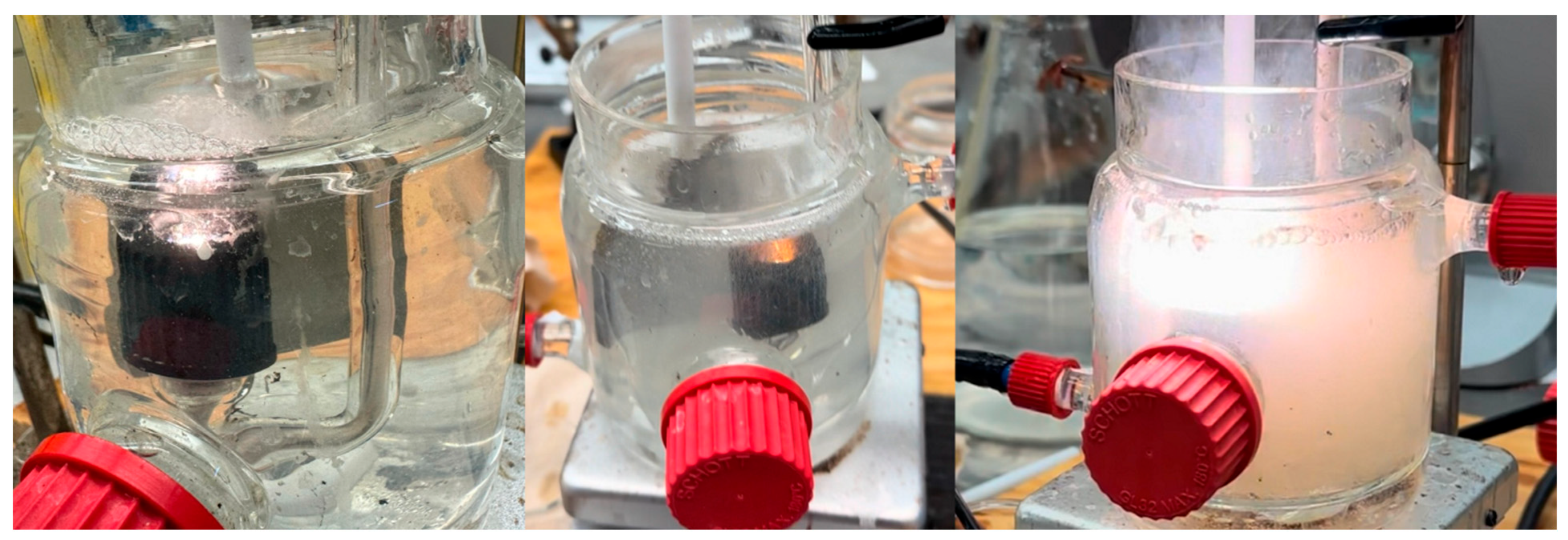
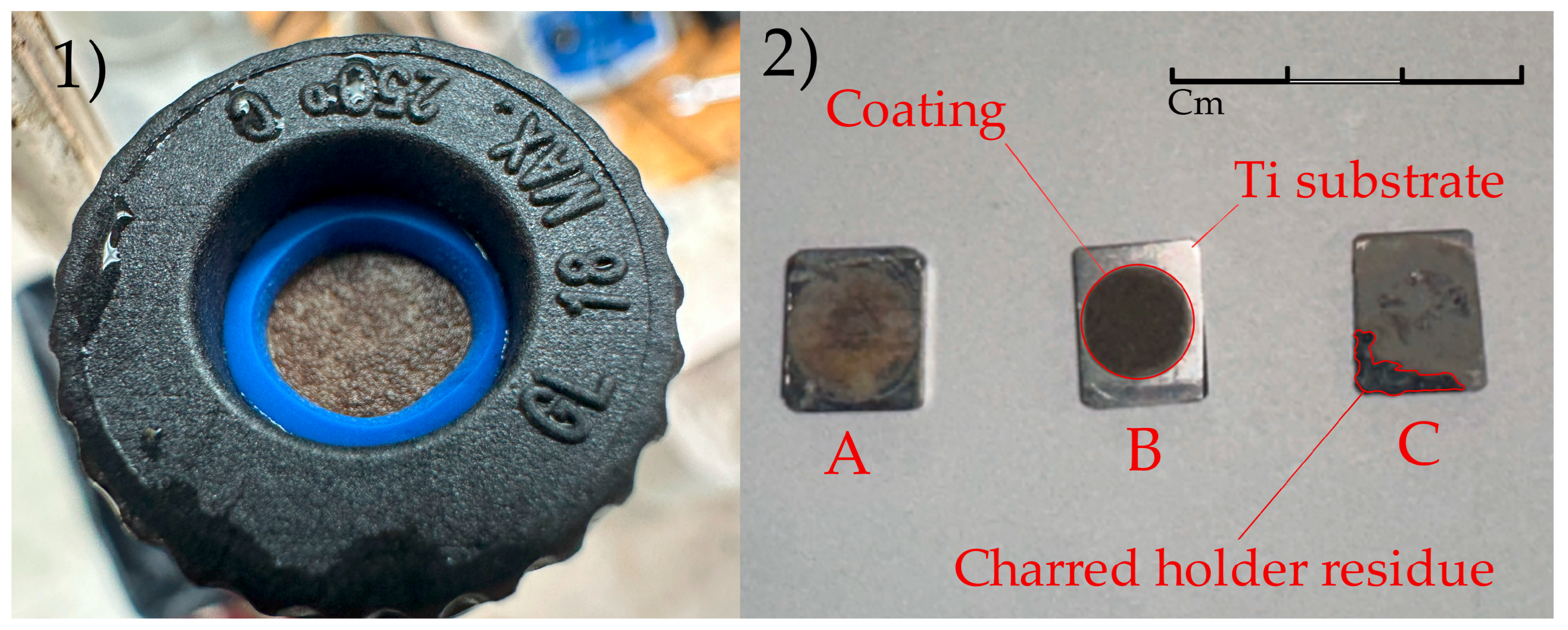
Like anodizing, PEO is an electrochemical process for creating a protective oxide layer on a metal substrate. While applied voltages range from 10 to 50 volts for standard anodizing and 20 to 120 volts for hard anodizing, PEO requires far higher voltages, typically between 150 and 800 volts [36]. In both processes, the natural oxide layer on the metal workpiece grows in response to the applied voltage. The resistance of this layer increases with its thickness, which eventually limits the thickness of non-porous anodized coatings to about 1.2 nanometers per applied volt [29]. At this point, the unique processes that separate PEO from anodizing begin. Once the voltage drop across the oxide layer reaches the breakdown potential of the oxide, discharge channels are formed in weak regions of the oxide layer, which can be seen as sparks on the surface of the anode [37]. Oxygen liberated by electrolysis and anions from the electrolyte are drawn into the discharge channel by electrophoresis, while alloying elements diffuse out of the substrate due to the high temperature and pressure caused by the discharge. These species combine to form oxides which are deposited on the channel walls, closing the channel as it cools [27,36,37]. The high temperature in the discharge channel also melts the nearby oxide, densifying and recrystallizing it. Sintering and annealing can also occur in regions further from the channel. After discharge channels are created, high-pressure gases escape, resulting in the formation of volcano-like blind pores on the surface [37]. When discharges first occur, they are relatively weak and uniformly distributed across the surface of the workpiece and can be seen as white sparks. As the oxide layer grows, the associated increase in the voltage drop across the layer causes the number of discharges to fall while their intensity grows. The color of the sparks also changes from white to yellow and eventually to orange-red. This represents the transition from the sparking stage to the microarc stage [36,38]. During the microarc stage, both the rate of coating growth and the roughness of the coating surface increase [36]. The intensity of the discharges continues to increase during the microarc stage, eventually causing damage to the oxide coating. PEO is generally stopped before the final strong arcing stage to avoid this damage [36,38,46]. Strong discharges also result in the characteristic “pancake” structure often seen in PEO coatings, as molten metal flows out of discharge channels and rapidly cools around the channel opening [47]. The progression of discharges throughout the PEO process is shown in Figure 2. An example of a coating produced on titanium alloy with this setup is shown in Figure 3 (1). Three coatings produced on titanium alloy samples are shown in Figure 3 (2), each showing a different amount of PEO processing. Sample A shows the thin oxide layer produced early in the process, which has a similar appearance to anodized metal. Sample B has a thicker, rougher coating that is much more easily distinguished from the substrate. Sample C has been subjected to the strong arcing stage, resulting in a highly uneven coating with charred material left on the surface due to damage to the sample holder.
Because the growth of the oxide layer occurs in discharge channels at weak points in the layer, PEO produces oxide layers with a very uniform thickness [36]. The properties of the oxide layer vary with depth. The highest concentrations of elements originating in the substrate are found deeper in the oxide layer, closest to the substrate, while elements originating in the electrolyte have higher concentrations closer to the surface of the layer [41]. PEO coatings consist of two main layers. The outer layer is more porous and less hard than the inner layer [41]. The structure of these layers varies between coatings, even when produced on the same substrate. Mortazavi et al. [46] and Friedemann et al. [48] both investigated the microstructure of coatings on commercially pure titanium. The former used an electrolyte composed of 0.1 M K4P2O7 and 0.02 M KOH, while the latter used 1.5 M H2SO4 and 0.3 M H3PO4. Mortazavi et al. [46] observed that during processing, the outer layer was quenched by the electrolyte, resulting in an amorphous structure at all tested current densities. The inner layer had both amorphous and crystalline regions, with higher current densities during processing resulting in a greater amount of mixture between the two phases. Friedemann et al. [48], on the other hand, found that crystallite size increased from the coating–substrate interface to the surface, attributed to the recrystallization of TiO2 during processing, with the lower layer of the surface consisting predominantly of amorphous phases. Amorphous phases could also be found surrounding the pores produced by strong discharges, resulting from a similar quenching effect as was observed by Mortazavi et al. [46].

2.2. Process Parameters

There are several parameters that influence the properties of PEO surfaces, summarized in Table 1. One important parameter is the type of current used in processing. Bipolar current modes have been shown to result in lower plasma temperatures, which leads to less damage of the oxide coating due to strong plasma discharges. This translates to less porosity and better corrosion resistance when compared to unipolar processes. The magnitude and duration of the positive and negative currents affect the final properties of the coating, with a greater proportion of negative current resulting in less porous coatings than when the positive and negative currents are equal [49,50]. For bipolar currents, frequency also has an impact on coating properties. Hussein et al. [47] observed that for aluminum, a 0.2 kHz current resulted in a higher growth rate and surface roughness than 2 kHz and 20 kHz currents, while a 2 kHz current reduced the number of strong discharges and resulted in fewer large pores. The 20 kHz current mode resulted in a thin surface with many holes and a more porous interface between the coating and the substrate compared to the 2 kHz modes. Two different 2 kHz cases were tested with different proportions of on time and off time for the current. Case A, with Ton = 100 μs and Toff = 400 μs, had better bonding between the coating and the surface but higher porosity compared to Case B, with Ton = 400 μs and Toff = 100 μs.
Processing time for PEO varies widely and has a significant impact on the resulting coating. Sela and Borodianskiy investigated processing times of 10, 20, and 30 min on zirconium alloy in a molten salt electrolyte [51]. The inner layer grew quickly to a thickness of 7–12 μm after 10 min, at which point the outer layer was only 1–4 μm. After 20 min, the inner layer had a more uniform thickness of 8–10 μm while the outer layer had grown to 10–17 μm. After 30 min, both layers had thicknesses of 10–12 μm. This demonstrates that while the thickness of the inner layer is not greatly affected by processing time on this timescale, the outer layer grows throughout the process. While this range of processing times is representative of many PEO studies, processing times as long as 60 min [57] or as short as 2 min [58] are sometimes seen. In addition to thickness, the phase content of the coating is affected by processing time. Wei et al. produced coatings on titanium composed of SnO2 and TiO2, using relatively brief processing times between 30 and 270 s [59]. Energy-dispersive X-ray spectrum analysis showed that tin content increased from 4.79% to 10.85%, while titanium content decreased from 8.88% to only 0.48%, showing the inclusion of more electrolyte elements over time. This initial variation in composition is significant for applications such as battery anodes that depend on the precise chemical properties of the coating.
Electrolyte composition is another important factor in the properties of PEO coatings. Li et al. [52] studied the different effects of silicate, phosphate, and mixed electrolytes on the growth mechanism and coating properties for titanium alloy. Silicate was found to have a lower breakdown voltage than phosphate, as well as reaching the breakdown voltage faster. The combined silicate–phosphate electrolyte had a closer breakdown voltage to the phosphate but reached it in nearly the same time as the silicate. While phosphate and silicate–phosphate had nearly identical ending voltages after 60 min of processing, the voltage for silicate only was much higher. The growth rate varied between electrolytes as well as over time, with silicate growing nearly twice as quickly during the second half of processing than the first half. Phosphate showed a higher growth rate than silicate at first but decreased sharply after only ten minutes. The combined silicate–phosphate followed a similar pattern but had a lower initial growth rate and higher final growth rate when compared to phosphate. After 60 min of processing, the silicate coating had a thickness of 83.2 μm, while the phosphate coating had a thickness of only 25.2 μm. Wu et al. [53] also evaluated the effect of different electrolytes on PEO coatings for titanium alloy. Aluminate, another common electrolyte for PEO, was studied in addition to phosphate and silicate electrolytes. Silicate and phosphate electrolytes both resulted in breakdown voltages around 190 V, while aluminate had a significantly higher breakdown voltage of 290 V. The thickest coating after ten minutes of processing was the phosphate-based at 2.19 μm, followed by aluminate at 1.81 μm and silicate and 0.75 μm. On AZ91 magnesium alloy, Mingo et al. observed that the inclusion of NaF in the electrolyte increases the porosity and growth rate of the coating [54]. On VT1-0 titanium, Bryzhin et al. compared electrolytes using a variety of chemicals. Coatings produced in the base sodium tungstate electrolyte contained WO3 and TiO2. Adding zinc acetate to the electrolyte produced coatings additionally containing tungsten blue and zinc-tungsten bronze. These coatings were thicker and had larger and denser pores than the plain tungstate coating. The addition of manganese acetate to the electrolyte led to the appearance of MnWO4 in the coatings, as well as a sharp reduction in both thickness and pore size [55]. Electrolyte conductivity is also important; in comparing different concentrations of H2SO4 and Na2SiO3 electrolytes, Lee et al. found that an ion conductivity higher than 50 mS/cm2 resulted in burning of the electrolyte and failure to produce a useful coating, regardless of the specific electrolyte composition [56].

3. Modification of PEO Coatings

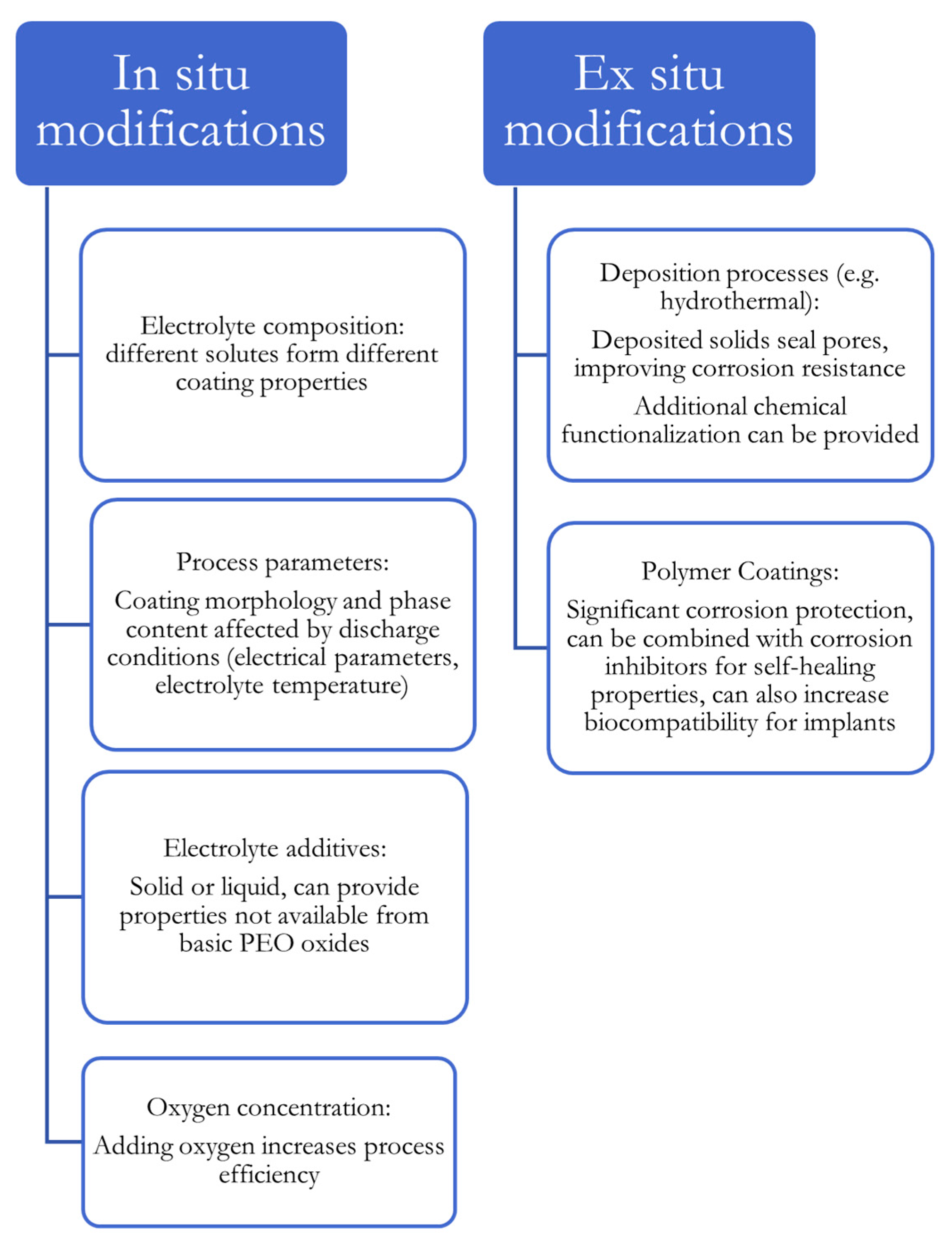
Modifications to the PEO process are divided into two categories: in situ, which directly change the conditions of the PEO process itself, allowing composition and morphology to be tailored in a single processing step, and ex situ, which apply treatments to already-produced coatings to enhance their properties. An overview of various modification types is given in Figure 4.

3.1. In Situ Modifications

3.1.1. Supplemental Oxygen
Hydrogen produced by electrolysis and thermal decomposition of water has been identified as a major factor slowing the synthesis of aluminum oxides in PEO, which can be mitigated by increasing oxygen concentration [60]. To increase the efficiency of the PEO process for battery electrode applications, Gim et al. used a polydimethylsiloxane spin coating on titanium substrate [43], whereas uncoated titanium immediately started arcing under an applied voltage, the coated samples had a five-minute period during which oxygen was liberated by electrolysis and trapped between the polymer and the substrate, after which, discharges began. This period allows a thick titanium oxide layer to grow via anodizing, improving the adhesion of the coating. The PDMS coating reduced the voltage required for the PEO process to begin, as well as increasing the duration of the reaction. The PEO coatings prepared using this method had a higher and more uniform thickness than those produced on bare titanium, with average thicknesses of 80.39 and 34.11 μm, respectively. Pore sizes were also larger, increasing from 0.95–6.19 μm to 12.38–33.57 μm. This is important for battery applications, as it increases the available area for ion transportation. Coin-type lithium-ion half-cells were prepared using the coated titanium, with cells prepared using PDMS having a higher areal capacity than those without. The concentration of oxygen can also be increased by increasing the strength of the anodic current relative to the cathodic current, favoring the release of oxygen in discharge channels. This improves coating growth but increases energy consumption. The electrolyte can be modified by adding hydrogen peroxide or blowing with ozone to increase oxygenation. Hutsaylyuk et al. [60] observed a 65% increase in thickness (60 to 100 μm) when 5 g/L hydrogen peroxide was included in the electrolyte. Higher concentrations of H2O2 resulted in the explosive formation of aluminum oxide, with molten material being ejected rather than trapped in the growing oxide layer. Ozone blowing at 5 mg/L·min resulted in a slightly lower thickness of 95 μm due to the lower efficiency of oxygenating the electrolyte. There was practically no effect on microhardness, residual stress, or Young’s modulus from either modification, but microplasticity increased from 0.48 to 0.51 with hydrogen peroxide and 0.54 with ozone, suggesting an increased ability to relax stresses during processing. Both modifications increased coating thickness and slightly decreased porosity without increasing energy consumption. Abrasive wear resistance was improved by both methods. Increasing oxygen concentration leads to the formation of harder α-Al2O3 (corundum) compared to the softer γ-Al2O3, with the hydrogen peroxide process producing the most corundum. Overall, the addition of hydrogen peroxide seems to provide a greater benefit than ozone blowing.
Figure 4. Summary of PEO process modifications.
Coatings 15 00592 g004

3.1.2. Molten Salt Electrolytes

Most PEO treatments are performed in aqueous solutions, which come with several drawbacks. As has been discussed, hydrogen generated through electrolysis and thermal decomposition can impede the PEO process [60]. Coatings produced in aqueous solutions are generally contaminated with compounds formed from the electrolyte. Due to the high temperatures involved in PEO, cooling is required for aqueous electrolytes. This in turn leads to rapid cooling of the coating, which leads to cracking. To address these problems, a novel method using molten salt in place of an aqueous solution was first explored by Sobolev et al. in 2017 [61]. Using a eutectic composition of NaNO3-KNO3 held at 280 °C in a nickel crucible, 1050 aluminum alloy samples were treated for 10 min with a 50 Hz pulsed current at a density of 70 mA/cm2. The resulting coatings exhibited similar porosity to aqueous-produced coatings in the outer layer, but no porosity in the inner layer. Additionally, the reduced cooling effect from the molten salt prevented the typical cracking entirely. In their 2018 follow-up, the authors directly compared aluminum samples treated in aqueous and molten salt electrolytes [62]. An aqueous solution of KOH and Na2SiO3∙5H2O was used alongside the same molten salt composition as in the previous paper [61]. Different current densities of 70 and 200 mA/cm2 were used for the molten salt and aqueous solutions, respectively, to obtain a consistent coating rate of 1 μm/min. The initial anodizing stage of the process was observed to occur up to 125 V in the aqueous solution, but only 30 V in the molten salt, due to its high conductivity. Overall, reaching the same coating thickness requires 60%–70% more current with an aqueous electrolyte than with molten salt. Energy dispersive X-ray spectroscopy (EDS) was used to confirm the presence of oxygen and aluminum in both coatings, with silicon present only in the aqueous surfaces. While X-ray diffraction showed that the molten salt coatings contained hard α-Al2O3 and γ-Al2O3 phases, the aqueous solution produced coatings that also contained softer η-Al2O3 and amorphous phases. The coatings produced with molten salt had thicker outer layers than those produced with the aqueous solution. The inner layers had hardness values of 806 ± 1.8 and 756 ± 3.1 HV10 for the aqueous and molten salt processes, respectively, while the outer layers had values of 642 ± 1.4 and 1051 ± 2.8. Although molten salt produces a slightly softer inner layer, there was more than a 60% increase in the hardness of the outer surface. Molten salt had a significant advantage in corrosion protection, with a corrosion potential of only −0.199 V, compared to −1.214 V for untreated 1050 alloy and −0.474 V for the aqueous electrolyte coating. In 2020, Sobolev et al. explored the effect of pulse frequency on coatings produced in molten salt [63]. A total of 7075 aluminum alloy samples were processed under similar conditions to the previous studies, with current pulsed at 200, 300, and 400 Hz. Frequency was observed to influence surface morphology, with higher frequencies resulting in larger pores and denser coatings. Hardness for both the inner and outer sublayers was positively correlated with pulse frequency. Corrosion resistance also improved with increasing frequency. When applied to titanium, the molten salt process produces crack-free coatings composed purely of anatase and rutile with good corrosion resistance and hydrophobicity [64,65]. Like with aluminum, the required voltage is far lower than with an aqueous electrolyte, while the produced coatings have less porosity and improved corrosion resistance [64]. The optimal frequency for titanium is lower than that of aluminum, with frequencies above 150 Hz leading to a reduced coating thickness and uneven structure [65]. The molten salt process has also been applied to aluminum–copper and zirconium alloys [51,66].

3.1.3. Low-Temperature Electrolytes

In contrast to the high-temperature molten salt processes, some authors have been able to increase the performance of aqueous electrolytes by reducing their temperature. Typically, PEO is performed with an aqueous electrolyte held at 10–40 °C [50,57,67,68,69]. In 2012, Habazaki et al. studied the formation of coatings on Ti-15-3 alloy in a K2Al2O4-Na3PO4-NaOH solution between 5 and 40 °C [70]. Peak voltage during processing increased with decreasing temperature, with 10, 30, and 40 °C all producing similar voltage responses. The voltage response at 5 °C showed a much faster increase than the others, reaching a peak voltage before shutoff of 400 V after 200 s, compared to 350 V after 300 s at 10 °C and 315 V after 400 s at 40 °C. The coating produced at 5 °C was denser, more uniform, and had far better wear resistance than the other coatings. Additionally, an α-Al2O3 phase was present in the 5 °C coating that was not detected in the other coatings. All coatings were composed mainly of Al2TiO5 with a metastable γ-Al2O3 phase. The aluminum in these phases is attributed mostly to the electrolyte composition due to the low percentage of aluminum in Ti-15-3. Franz et al. [71] studied the use of refrigerated electrolytes for TiO2 coatings, finding that the weight fraction of anatase could be increased from 45%–70% to 93% by using a cryostat to reduce the electrolyte temperature from 20 °C to −3.5 °C, almost to the 0.5 M H2SO4 solution’s freezing point. Porosity increased with temperature, from 5.5% at −3.5 °C to 14% at 20 °C. Pore size, however, followed a less simple relationship with temperature: at −3.5 °C, the minimum average pore size of 120 nm was obtained, increasing to the maximum of 350 nm at 0 °C, then falling again to 220 nm at 20 °C.

3.1.4. Electrolyte Conductivity

The working voltage for PEO can also be reduced by increasing the concentration of aqueous electrolytes. Chen et al. [72] performed PEO on LA91 Mg-Li alloy in a solution containing 50 g/L NaOH, 40 g/L Na2SiO3, and 40 g/L C6H5Na3O7·2H2O. These concentrations are significantly higher than those typically seen in PEO electrolytes; NaOH is usually used in concentrations of 2 g/L or less, while other components such as silicates, aluminates, and phosphates are used in concentrations of 20 g/L or less [53,57,73,74,75]. The use of such a concentrated electrolyte allowed the PEO process to begin at a voltage of 60 V, compared with the typical 150–450 V for Mg-Li alloy [72]. The authors also investigated the use of the ionic liquid 1-butyl-3-methylimidazole tetrafluoroborate (BmimBF4), a known corrosion inhibitor in steels, as an additive to the electrolyte. Concentrations of BmimBF4 up to 40 mL/L were tested. The addition of BmimBF4 had the unexpected effect of reducing electrolyte conductivity, therefore increasing the process voltage, whereas most electrolyte additives cause an increase in conductivity. Despite this, the breakdown voltages around 80 V seen with the ionic liquid additives remain well below those typically seen. There was a substantial effect on morphology from the additive, with the addition of only 10 mL/L BmimBF4 resulting in a decrease in porosity from 4.44% to 2.39%. At 20 mL/L, porosity increased to 11.75% before decreasing to 7.98% and finally 6.45% at 30 and 40 mL/L, respectively. Coating thickness and roughness followed similar trends, reaching their maximum values for an ionic liquid concentration of 20 mL/L before decreasing at higher concentrations. Contact angle tests showed a similar story. Surfaces produced with 0 and 40 mL/L BmimBF4 had very close water contact angles of 21.4° and 21.8°, respectively, whereas the 20 mL/L surface achieved a much higher contact angle of 66.8°, demonstrating far greater hydrophobicity. Electrochemical impedance spectroscopy (EIS) tests showed that the 20 mL/L surface also had the highest total resistance to corrosion.

3.1.5. Particle Additives

The PEO process can also be modified with the addition of solid particles to the electrolyte, which is commonly used to improve corrosion resistance [42]. A wide range of particles can be used, with the main parameters affecting their incorporation in the coating being size and melting point. Particles can be embedded reactively or inertly, with particles having low melting points being more likely to embed reactively [76]. Small particles, which are more likely to be embedded reactively, can travel through smaller pores and are incorporated throughout the PEO process, while larger particles may only be able to fit in the large discharge channels produced at the end of the process [42,77]. Charge is also important; a negative charge allows particles to be drawn to the workpiece by electrophoresis [42]. Particles are often observed to reduce porosity by filling in pores and channels in the coating, although some sources show little effect on morphology [76,78,79]. Roughness can be observed to decrease with small particles and increase with large ones [79,80]. An example of solid particles providing properties that could not be obtained through the regular PEO process is the use of graphite flakes for self-lubrication. In 2016, Yin et al. studied the effects of graphite flakes on the friction and wear of coatings produced on aluminum alloy [81]. PEO was performed in a silicate electrolyte with and without the addition of 10 g/L flake graphite-dispersed ethyl alcohol with an average grain diameter of 0.7 μm. Friction and wear tests were performed under dry and wet conditions. Between the two PEO coatings, the graphite-containing coating had consistently lower friction. Although bare aluminum had a comparable COF to the graphite-containing coating under a 10 N load in dry conditions, all other tests give an advantage to the PEO coatings that becomes greater with increasing loads, especially under wet conditions. While bare aluminum had a coefficient of friction near 0.65 for all loads under wet conditions, the PEO coating with graphite reaches a value as low as 0.3 for the 30 N load. The effect on wear is even more pronounced. Under both dry and wet conditions, wear rates for both PEO coatings are multiple orders of magnitude lower than those of the bare aluminum, with graphite-containing coatings experiencing the least wear. As PEO coatings typically have high coefficients of friction, it is valuable to be able to provide them with self-lubricating properties.

3.1.6. Microstructure Formation Mechanisms

Because PEO coatings are formed from a combination of substrate and electrolyte species, the specific alloy used in the substrate has a substantial impact on the quality of the final coating. Štrbák et al. [82] compared the microstructure and corrosion resistance of coatings on AZ91 with previous results [83] with AZ31 magnesium alloys. These alloys differ in their aluminum content: 9% and 3%, respectively. As such, AZ91 contains more intermetallic compounds such as Mg17Al12. During PEO processing, stronger discharges occur around these compounds, resulting in an increased growth rate relative to AZ31 under the same conditions, but producing a less homogeneous coating with a higher roughness and more defects. Despite these defects, corrosion resistance was significantly improved with the use of AZ91 alloy; the polarization resistance Rp for coated AZ31 after 24 h in 0.1 M NaCl solution was only 14% that of coated AZ91. The corrosion current icorr was 27 times higher for AZ31 than AZ91. The corrosion potential Ecorr was more positive for AZ91 than AZ31. The effect of microstructural differences on coating qualities is important for applications for which multiple alloys are available and may not be obvious from comparing the bare substrates: while Rp for coated AZ31 was only 14% that of coated AZ91, the as-cast AZ31 had a value more than twice that of the as-cast AZ91 after the same 24-h NaCl exposure [82,83].

3.2. Ex Situ Modifications

Frequently, ex situ modifications to PEO coatings are focused on improving long-term corrosion and tribological performance. While PEO can provide better protection than the natural oxide coating on bare alloys, its porous structure makes it susceptible to long-term damage [42,44,45,54,84,85,86,87,88,89]. Several techniques have been explored for sealing the defects present in PEO coatings to improve coating performance.

3.2.1. Hydrothermal Sealing

A simple example of such a sealing process was explored by Chu et al. in 2013 [84]. One method the authors tested to improve the corrosion resistance of magnesium was simply boiling the coated part in water, producing new oxides and hydroxides that filled in many of the pores and discharge channels. The authors compared this treatment with zirconia sol-gel and organic gelatin-hydroxyapatite coatings. The boiling treatment was able to completely seal smaller pores and reduce the size of larger pores. Shrinkage of the zirconia sol-gel coating during drying led to an increase in pore size. Because the gelatin-HA coating was applied in a liquid state, it was able to completely cover and seal the PEO surface. All three coatings succeeded at reducing the corrosion potential and current density: boiling in water reduced Ecorr by 35% and icorr by 76%, zirconia sol-gel reduced Ecorr by 14% and icorr by 92%, and gelatin-HA reduced Ecorr by 75% and icorr by 98%. Long-term corrosion tests on the gelatin-HA coating showed little change in phase composition or morphology after 28 days submerged in simulated body fluid. In simulated intestinal fluid, the gelatin-HA coating was able to prevent severe corrosion damage, characterized by large-scale fractures, for up to 70 days.
Another study comparing PEO post sealing techniques was performed by Mingo et al. in 2018 [54]. The same principle used by Chu et al. [84] in their boiling water experiments can be applied to solutions of various chemicals, with non-soluble precipitates being deposited in the pores and discharge channels of the PEO coating. Mingo et al. studied three solutions: two aqueous solutions of cerium salts and sodium stannate and one solution of octadecylphosphonic (ODP) acid in ethanol. The cerium sealing resulted in a flake structure, likely due to dehydration of the coating. The outer pores were partially blocked, but the inner layer of the PEO coating was not impacted. The amount of cerium present in the sealant increased with the addition NaF in the PEO electrolyte. In contrast to the flake structure of the cerium-based coating, immersion in a sodium stannate solution resulted in a coating of spherical granules 0.63 μm in diameter. While the pores in the PEO coating were not filled, deposition occurred deeper in the coating than with the cerium solution. Unlike with the cerium-sealed surfaces, the concentration of tin deposited did not appear to be significantly influenced by NaF. The ODP acid treatment produced a uniform layer, believed to be a monolayer, over the entire surface. Both the cerium and ODP acid sealings resulted in far higher contact angles than the unmodified surfaces, although still below the 90° threshold for hydrophobicity. To test corrosion resistance, a 7-day salt fog test was performed. While all sealing techniques resulted in less affected surface area compared to the base PEO specimens, the best results were obtained from the cerium and ODP sealing processes on PEO coatings that included NaF. Because NaF increases the size of pores and reduces their number, these sealants can more effectively penetrate and cover the surface. In addition, the formation of MgF2 during the PEO process may help facilitate the formation of the ODP monolayer through hydrogen bonding. This result was also observed in electrochemical tests, with much better improvements in corrosion resistance occurring in coatings prepared with NaF. The corrosion resistance of the ODP coating was better in the short term, while the physical, rather than chemical, protection provided by the cerium and stannate coatings allowed them to perform better with long-term exposure.

3.2.2. Polymer Sealing and Corrosion Inhibitors

In addition to hydrothermal sealing techniques, polymer sealants can be used to improve PEO coatings [84,89,90,91,92,93,94]. To improve the corrosion resistance of magnesium, Li et al. used epoxy to seal an ionic corrosion inhibitor, 1-(3-((N-n-butyl)aminecarboxamido)propyl)-3-hexadecyl imidazolidine bromide (M-16), in the pores of a coating produced with PEO [94]. After PEO processing in a silicate electrolyte, samples were soaked in a solution of M-16 in ethanol. This was performed under vacuum to prevent trapped air from blocking the inhibitor. Sealing was accomplished by spraying a commercial epoxy primer over the PEO/M-16 composite. The epoxy layer was significantly thicker than the PEO layer, at 153 μm vs. 10.2 μm, respectively. Water contact angle was measured to characterize the wettability of the surfaces. Hydrophobic surfaces have high contact angles, preventing water from easily spreading over the surface. This is beneficial for corrosion resistance, as less of the surface is exposed to the corrosive substance. Lower contact angles can be desirable in other situations, such as promoting tissue ingrowth for biomedical implants [51,90]. In this case, the contact angle was 64.76° for bare AZ31 alloy, 45.22° after PEO, 20.45° with M-16 deposited, and 79.82° with epoxy over the PEO/M-16 coating [85]. Bare AZ31 had the largest corrosion potential and current density (−1.599 V, 1.473 × 10⁻⁶ A/cm2). The full PEO/M-16/epoxy saw only a modest change in corrosion potential but saw a substantial reduction in corrosion current density, with respective values of −1.548 V and 9.7 × 10⁻⁹ A/cm2. In 2021, Liu et al. [95] used a different polymer, polyurethane, to seal M-16 inside PEO coatings on magnesium. Thanks to the shape-memory effect, polyurethane can be used to create a coating that self-heals with thermal treatment. When the composite coating is scratched, the M-16 contained in the PEO layer provides corrosion protection until the polyurethane is healed. As well as protecting the substrate, M-16 helps the healing process of the polyurethane by separating it from corrosion products such as Mg(OH)2, the accumulation of which can cause the polymer to detach from the substrate, inhibiting the repair process. The following year, Zhang et al. [87] used a different corrosion inhibitor, octadecyl triphenyl phosphonium bit(tri-fluoromethylsulfonyl)amide ([OTP][NTf2]), sealed with a superhydrophobic silica/epoxy resin coating. This coating had an extremely high water contact angle of 164.4°. The hydrophobicity of the surface gave it excellent anti-fouling properties. Water droplets easily picked up carbon powder from the coated surface and carried it away as they rolled off, while the two merely mixed and spread over the hydrophilic bare magnesium surface. In long-term corrosion tests, samples were scratched in a cross shape before immersion in 3.5 wt% NaCl solution for 25 days. Bare magnesium was severely corroded after 7 days, while the bare PEO, PEO with [OTP][NTf2], and PSE-sealed surfaces only showed minor corrosion around the scratches. While all samples deteriorated somewhat within 25 days, the PSE-sealed surface showed no signs of corrosion outside the immediate area of the scratch.

4. Applications for Modified PEO Coatings

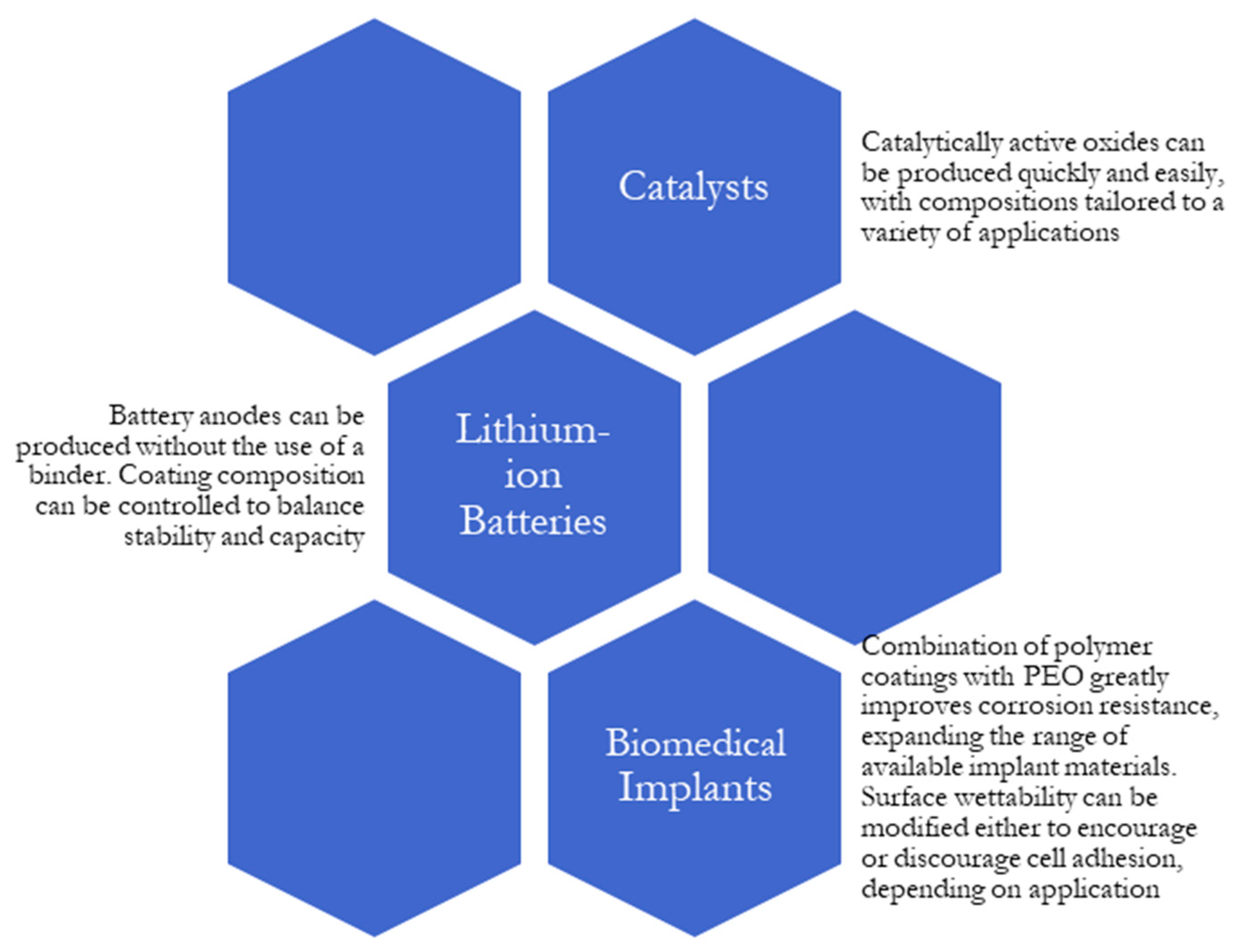
The wide range of modifications available for the PEO process allows coatings to be tailored to a variety of fields of research, including catalysts [37,55,71,96,97,98,99,100,101,102,103,104,105,106,107,108,109,110], batteries [43,56,58,111,112], and biomedical implants [51,113,114]. This section will examine the ways in which the PEO process has been modified to meet the specific needs of these applications.

4.1. Catalysts

4.1.1. Wastewater Treatment

Photocatalysis is an emerging technology in the field of wastewater treatment that breaks down contaminants with oxidation and reduction reactions driven by light. While it can decompose a wide range of contaminants using reusable catalysts without additional post-treatment steps, photocatalysis is typically performed using powders that can suffer from aggregation and agglomeration at high concentrations, must be separated from the treated water after use, and risk being released into the environment [37,115]. These drawbacks can be mitigated by depositing the catalyst on a substrate. One of the most efficient photocatalysts for wastewater treatment is TiO2, which is easily produced on titanium substrates using PEO [37,55,113]. Because of PEO’s low cost, simplicity, low environmental impact, and applicability to large and complex surfaces, it is an attractive technology for producing wastewater photocatalysts. Many combinations of substrate and electrolyte have been tested to produce the most efficient photocatalytic coatings. In their review, Karbasi et al. compared the effectiveness of a variety of PEO coatings at breaking down various environmentally hazardous industrial dyes [37]. A parameter called the photocatalytic coating efficiency (PCE) was used to account for differences between experiments. The highest-scoring coating components were found to be WO3 [104,108,109] and V2O5 [105,106,107] when used to decompose methylene blue dye under UV irradiation, with coatings on titanium substrates slightly outperforming those on aluminum. The high performance is attributed to a low electron-hole recombination rate and high affinity for unpaired electrons for WO3 and a high number of redox sites for V2O5 [37].

4.1.2. Water Splitting

Specialized catalysts produced by PEO have been studied for applications other than water treatment. In 2013, Shin et al. [102] were the first to use PEO to produce electrodes for water splitting. Four different electrodes were produced on titanium foil: one on an untreated surface, one on a nonporous “barrier” coating produced by anodizing at 60 V for 4 h, one on a nanotubular coating produced by anodizing at 20 V for 4 h, and a microporous coating produced by PEO at 200 V for 2 h. A 1 M H3PO4 solution was used for all three processes, with the nanotubular and microporous solutions also containing 0.5 wt% HF. Electrodes were fabricated by dropping 0.05 mL of 0.03 M solutions ruthenium chloride hydrate and iridium chloride hydrate on the samples and heat treating at 450 °C for 1 h. This led to the formation of RuO2, which improves the catalytic performance of the TiO2 coatings, and IrO2, which improves dimensional stability, increasing the life of the electrode. Linear sweep voltammetry was used to estimate the onset potential for oxygen evolution. The microporous PEO surface performed best, with an onset potential of 1.32 V. Both the barrier and untreated surfaces had onset potentials of 1.45 V, while the potential for the nanotubular surface was 1.47 V. The authors attribute the difference in onset potential to the distribution of RuO2. The barrier surface had a low surface area but high susceptibility to penetration by Ru4+ ions, resulting in less RuO2 remaining at the surface to provide catalytic sites compared to the microporous PEO surface, which had large pores but more resistance to penetration due to a denser TiO2 structure. In the nanotubular surface, RuO2 was formed deep in the nanotubes, where oxygen liberated by electrolysis could not easily escape, with little being deposited at the surface.
In 2016, Woo and Sung [103] used PEO to produce electrodes for photoelectrochemical water splitting, making use of the discovery by Fujishima and Honda in 1972 [116] that titania could decompose water using only visible light without the application of an external voltage. Titanium plates were treated with PEO at varying voltages (350 ± 30 and 450 ± 30 V) and processing times (5, 10, and 20 min) [103]. Electrodes were prepared using two aqueous solutions: one containing 12 g/L Na2HPO4 and one containing 4 g/L acetamide and 1 g/L NaOH. The latter was used to produce nitrogen-doped TiO2 coatings with improved energy bandgaps to better facilitate visible light photoelectrolysis. The phases present in the coatings were influenced by the voltage during processing; coatings produced at 350 V were nearly pure anatase, while those produced at 450 V contained both anatase and rutile. The rutile content of the surface increased with processing time. N-doped TiO2 samples outperformed undoped samples. The photocurrent density and photoconversion efficiency increased with rutile content: pure, undoped anatase had values near 0, while N-doped anatase reached a current density of 0.2 mA/cm2 and an efficiency of 0.3%. At 20% rutile, the current density and efficiency were 1.5 mA/cm2 and 0.15% for undoped samples, 0.55 mA/cm2 and 0.65% for N-doped samples. The performance of the 19% rutile N-doped electrodes was further improved by mixing NaOH and KI in the electrolyte. Various ratios of NaOH to KI were tried, with the total concentration of the two fixed at 1.0 M. The best results were achieved at 3:1 NaOH/KI, with a photocurrent density of 0.8 mA/cm2 and a photoconversion efficiency of 0.7%, outperforming many previous TiO2 water-splitting photocatalysts. In the same year, Franz et al. [71] found that the photocurrent density of TiO2 catalysts was influenced by electrolyte temperature. Catalysts produced at 20 and 15 °C only achieved densities of about 0.02 mA/cm2, while the coatings produced at 0 °C reached 0.18 mA/cm2. The effects of thermal annealing were also tested. No change in phase composition or morphology was observed, while photocurrent response was negatively affected. While film thickness and processing time did not have a significant effect on photocurrent response, the photocurrent density for electrolyte temperatures below 10 °C increases almost linearly with film thickness. The effects of electrolyte heating lead to a significant decrease in photocurrent density for long processing times at low temperatures: although a density of 0.18 mA/cm2 was achieved with a sample processed at 0 °C for 5 min, processing for 20 min resulted in a mere 0.025 mA/cm2. More recently, Lin et al. [99] produced N-doped photocatalytic electrodes that use both the substrate and electrolyte as nitrogen sources by coating the substrate in TiN using air-based sputtering prior to PEO in a 0.02 M NaPO3, 0.13 M NaOH solution with varying concentrations of NH4OH.

4.1.3. Diesel Applications

PEO-produced catalysts have also been studied for diesel exhaust treatment. In addition to hydrocarbons, carbon monoxide, and nitrogen oxides, which are also found in gasoline exhaust, the diesel combustion process produces particulate matter which must be removed [117]. Diesel exhaust systems must also operate in a relatively low-temperature, oxygen-rich environment when compared to gasoline exhaust systems, and must avoid unwanted SO3 and H2SO4 generation from the sulfur content of the diesel fuel. In 1999, Tikhov et al. [96] produced honeycomb catalysts using PEO on aluminum foil. To allow exhaust gases to flow, honeycomb cells were produced by rolling stacks of flat and corrugated sheets into a spiral. After PEO, the samples were calcinated at 600 °C for 2 h. Next, a secondary support layer was produced by impregnating the coating with lanthanum nitrate solution, calcinating for another hour, then impregnating with a water suspension of ceria-modified γ-alumina before drying at 120 °C for 4 h and further calcinating for 2 h. A variety of active components were then added to produce different catalysts: platinum group metal and manganese oxide catalysts were created by impregnating the coatings with precursor solutions, while Cu-Sr/ZSM-5 and La-Ce-Cu perovskite catalysts were produced by mixing fine powders of the active components into an alumina suspension and washcoating the support layers. These processes were followed by further drying and calcination. A diesel converter was then assembled based on a standard bus muffler, with cells containing different active components being stacked in sequence to provide multiple catalytic functions. After four months of trials in Moscow city buses, the converters were demonstrated to remove 70%–80% of particulates, carbon monoxide, and hydrocarbons; at least 50% of nitrogen oxides were removed. Lebukhova et al. [118] used a similar process to produce catalysts for diesel soot combustion; PEO was first performed on VT1-0 titanium alloy wires in a Na2SO3/NaOH electrolyte, followed by an extraction-pyrolytic (EP) treatment in which the wires were soaked in a solution containing copper and molybdenum before drying in an oven. This produced a catalytically active layer of CuMoO4 over the TiO2 and SiO2 formed during PEO. In the absence of a catalyst, soot combustion initiated at 405 °C (Ti) and reached maximum intensity at 530 °C (Tm). After two EP treatments, the molybdate catalyst reduced Ti and Tm to 270 and 410 °C, respectively. This decrease in combustion temperature is significant for exhaust treatment, as reactions must occur at exhaust gas temperatures, typically 120–360 °C at startup and 500–800 °C during operation. The combustion reaction was also more selective in the presence of a molybdate catalyst. Both CO and CO2 are produced during soot combustion, with the percentage of CO2 in the exhaust gases rising from 80.2% to 96.0% in the presence of the molybdate catalyst. Using a modified PEO coating, the amount of harmful particulate matter in exhaust can be reduced while producing less harmful byproducts.
As regulations have grown stricter, not only for emissions but for the content of the fuel itself, PEO-produced catalysts have also been studied for fuel production applications. The United States Environmental Protection Agency began phasing in ultra-low-sulfur diesel fuel in 2006, requiring stronger desulfurization to be employed to reach the mandated 15 ppm sulfur content [119]. This has strained the capabilities of the hydrodesulfurization (HDS) process traditionally used in diesel production, increasing the temperatures, pressures, processing times, hydrogen consumption of the technique, in turn increasing production costs. Oxidative desulfurization (ODS) can be performed at low temperatures and pressures, does not require hydrogen, and is capable of oxidizing polycyclic organic sulfides, and as such has been studied as both an alternative and complement to HDS [55,110,119,120,121]. Table 2 summarizes the performance of a number of PEO-produced coatings in converting various sulfur contaminants found in diesel fuel. In 2005, Caero et al. [119] demonstrated the ability of a TiO2-supported V2O5 catalyst to oxidize several thiophenes present in the refining process, including refractory molecules such as 4,6-DMDBT that cause challenges reaching lower sulfur levels with HDS. Rakhmanov et al. tested compounds of different transition metals (Mo, W, and V) in hydrogen peroxide, achieving a 61% desulfurization using Na2WO4∙2H2O [122]. Subsequent tests were performed with other tungsten compounds, achieving 72% desulfurization with WO3, 75% with WO3∙H2O, and 82% with H3PMo6W6O40. The high performance of tungsten oxides led Rudnev [121] et al. to study the use of PEO to produce ODS catalysts using aluminum and titanium substrates in tungsten-containing electrolytes. Sodium tungstate, phosphotungstate, and ammonium paratungstate were all tested as tungsten sources. Two broad categories of coatings were produced: coatings I, containing about 1 at.% W(VI) distributed in SiO2 + TiO2 or SiO2 + Al2O3, and coatings II, made up of crystalline tungsten compounds like WO3 and Al2(WO4)3. While coatings I had higher initial thiophene consumption rates than coatings II, only two of the five coatings in the group achieved final conversion rates around 50%. In contrast, coatings II all achieved conversions of over 40%, despite a lower initial rate. However, coatings II came with the drawback of significantly reduced stability, losing 5%–10% of their weight after three desulfurization cycles, compared with 0%–2% for coatings I. Coatings were also characterized by their turnover frequency, calculated by dividing the initial rate of thiophene consumption by the concentration of tungsten in the coating. The highest turnover frequency of 178 h−1, representing the most catalytic activity per unit of tungsten, was achieved with an Al-Mn alloy substrate oxidized in an electrolyte of 0.1 M Na2SO3 and 0.015 M Na2WO4, belonging to coatings I. This coating was also one of two that did not demonstrate any weight loss after use.
Continuing this research, Tarkhanova et al. [110] used PEO to produce catalysts containing various ratios of cerium and zirconium. These elements were chosen for their ability to form catalytically active mixed oxides that remain stable in aggressive environments, potentially giving them an advantage in the presence of sulfuric acid formed by thiophene oxidation. Five coatings were produced, using electrolytes containing a total of 0.49 M Zr(SO4)2 and Ce2(SO4)3 in varying proportions. To improve the activity and stability of the catalysts, the ionic liquid 4-(3′-ethylimidazolium)-butanesulfonate was deposited by soaking samples in a 1:1 aqueous solution before drying under vacuum. The first catalysis tests were performed without ionic liquid on samples processed for 5 min; the highest thiophene conversion (43%) was obtained with an electrolyte zirconium fraction of 0.6. The second set of tests was used to optimize PEO processing time, with the conversion increasing to 67% for the 15 min sample. Finally, the ionic liquid was tested, raising the thiophene conversion to 89%. After five consecutive tests, the activity of the sample without ionic liquid fell by 10%–15%. In contrast, no degradation in performance was seen when ionic liquid was used, presenting a potential solution to the stability problem observed in this and the previous paper. A sulfur content of 7 ppm was achieved, bringing the performance of the catalyst in line with modern environmental requirements.
In 2020, Bryzhin et al. [55] combined PEO-produced tungsten catalysts with ionic liquid deposition. Titanium samples were first processed in two different Na2WO4 solutions containing different concentrations of acetic acid for different pH values. Thiophene conversion was higher for the pH 6.8 solution than the pH 5.5 (34% vs. 20% on first cycle, respectively), so it was used as the basis for further tests. Two more solutions were prepared with the same composition, with the addition of either manganese or zinc acetate. Between the tungsten, tungsten–manganese, and tungsten–zinc catalysts, tungsten–zinc reached the highest thiophene conversion rate of 49%. It also had the least loss of activity, losing 20% after 5 cycles compared to 24%–25% for the other catalysts. While its performance was the most stable, the tungsten–zinc catalyst also experienced a 4.8% weight loss compared to 2.4% for pH 6.8 tungsten, 2.9% for pH 5.5 tungsten, and 4.3% for tungsten-manganese. Like with the prior cerium–zirconium catalyst, the deposition of 4-(3′-ethylimidazolium)-butanesulfonate ionic liquid both prevented the loss of activity and increased activity overall, reaching a thiophene conversion of 82%. This was further increased to 93% using fractional H2O2 loading, adding two 0.2 mL quantities over the course of the desulfurization test rather than using 0.4 mL from the start. Desulfurization of diesel fuel achieved a 99.6% conversion rate using this method, with a residual sulfur content of only 6 ppm.

4.1.4. Other Catalytic Applications

Catalysts produced using PEO have been studied for a variety of other applications. Rudnev et al. [98] have studied the use of nickel- and copper-containing PEO layers to catalyze the oxidation of CO to CO2, finding that catalytic activity can be increased by immersing the PEO coatings in a solution of Cu(NO3)2 and Ni(NO3)2, followed by annealing, forming a layer of NiO and CuO on the surface. This had the result of lowering the 50% conversion temperature from 410–160 to 310–320 °C for aluminum and 410–450 to 210–240 °C for titanium. Later, Shtefan and Smirnova [97] compared different electrolyte compositions for titanium-supported catalysts for the same application. The resulting coatings were TiOx-CeOy, TiOx-CeOy-ZrOz, and TiOx-CeOy-ZrOz-CuOn. The coating containing only cerium and titanium oxides reached less than 60% conversion at a temperature of 450 °C. The addition of zirconium resulted in a conversion close to 90%, while temperatures were not greatly affected. The coating containing cerium, zirconium, and copper oxides performed far better than the others, reaching 100% conversion at only 140 °C. This was lower than even platinum, which reached 100% conversion at over 200 °C.

4.2. Lithium-Ion Batteries

In addition to its use as a catalyst in a variety of applications, titania has been studied as an anode material for lithium-ion batteries due to its high theoretical capacity, volumetric stability, and operating voltage [123]. Being much simpler and more efficient than other contemporary titania production methods such as hydrothermal synthesis, PEO is poised to provide substantial benefits to the field [58]. Binders and conductive materials are generally used in the production of TiO2 anodes, reducing the proportion of active material to 60%–90% [111]. In contrast, PEO allows TiO2 coatings to be produced without the use of a binder, increasing the amount of active material, while its porous structure maximizes the availability of the material [56,111]. As such, PEO has the potential to not only produce anodes more efficiently, but also with better performance than other methods. While TiO2 is a useful anode material in and of itself, oxides of other light metals, such as Al2O3, MgO, and ZrO2, do not undergo the same reversible lithium intercalation reactions as TiO2, so can only be used in composite anodes to improve the properties of other materials [58]. As such, research on PEO for batteries has focused on titanium substrates. Table 3 summarizes the stable capacities achieved using different coating types.
In 2017, Lee et al. [56] used PEO to produce anodes from titanium foil, seeking to combine the cycling stability of TiO2 with the superior capacity of SiO2. Foil samples were treated using an array of electrolytes containing varying concentrations of H2SO4 and Na2SiO3, then used to build lithium-ion cells with platinum mesh counter electrodes. The presence of SiO2 in the oxide layer resulted in an increase in open circuit voltage from 1.75 to 2.7 V at all concentrations. The best-performing anode, produced with the highest concentrations of both H2SO4 and Na2SiO3 (0.2 and 0.4 M, respectively), had an areal capacity over 700 μAh/cm2. This significantly outperformed previous TiO2 electrodes, which were generally in the range of 50–250 μAh/cm2. This areal capacity increased gradually during cycling, attributed to an increase in the number of active SiO2 sites in the porous structure during the formation of the solid–electrolyte interface of the cell. A corresponding decrease in internal resistance was observed with electrochemical impedance spectroscopy. Disassembly and inspection of the cell after 200 charge–discharge cycles at 2.5 V did not reveal any change in morphology, demonstrating the anode’s volumetric stability.
Tao et al. [111] produced electrodes using PEO on titanium in an aqueous solution of Na2SiO3∙9H2O and NaOH, followed by a hydrothermal processing step. This involved putting the sample in a solution of 20 mL water, 10 mL hydrazine hydrate, and 1.5 mL hydrochloric acid, followed by 20 h in an autoclave at 220 °C. The hydrothermal reaction self-dopes the TiO2 coating with Ti3+ ions, introducing oxygen vacancies that improve conductivity while also increasing crystallite size for greater cyclic stability. Cyclic voltammetry revealed a reduction in ohmic resistance from 13.38 to 2.348 Ω with hydrothermal processing, while charge-transfer resistance reduced from 2096 to 202.4 Ω. These improvements are attributed to both the presence of oxygen vacancies and increased contact area due to the flocculent morphology of the hydrothermally treated film and presence of nanoparticles on the surface. The initial volumetric capacity of the hydrothermal anode was 751 mAh/cm3, more than five times the value of the untreated anode. While the capacity was reduced during cycling, the stable value of 520 mAh/cm3 after 900 cycles was still higher than other, non-PEO-based titania battery anodes.
Like SiO2, MoS2 has strong potential as an electrode material due to its high capacity but suffers from extreme volume changes (up to 100%) during lithiation–delithiation. Sun et al. [58] in 2021 used magnetron sputtering after PEO on titanium to produce a thin film of spherical MoS2 particles over the TiO2 PEO layer for use as a composite anode. Using this method, a stable specific capacity of 560 mAh/g was achieved. While the initial capacity of the TiO2/MoS2 anode was lower than that of pure MoS2, the poor cycling stability of MoS2 caused it to fall behind TiO2/MoS2 within roughly 10 charge–discharge cycles. The final capacity of the TiO2/MoS2 anode at 50 μAh/cm2 was over 90% of the capacity before rate performance testing up to 1000 μAh/cm2, further demonstrating the stability of the composite electrode.
Another material commonly considered for lithium-ion battery anodes is SnO2. In addition to its large capacity, SnO2 is inexpensive and environmentally friendly, but suffers from an even worse volume change than MoS2 (up to 300%), has a low conductivity, and undergoes an irreversible reaction in its first lithiation cycle that both reduces the coulombic efficiency of the first cycle and produces inert Sn particle clusters that reduce the cell’s activity in subsequent cycles. In 2022, Wei et al. [59] fabricated SnO2-TiO2 anodes using a solution of Na2SnO3 and Na3PO4 as the electrolyte. Processing times of 30, 120, and 270 s were used, with 120 s providing the best performance. Longer processing times favor more SnO2 in the coating, increasing initial capacity. This is balanced by a decrease in TiO2, reducing long-term stability. Although the 270 s sample showed more than twice the capacity as the 30 s sample on the first cycle, its capacity fell far faster during cycling, falling below the 30 s sample within 75 cycles. In contrast, the 120 s sample maintained a capacity approximately twice that of the 30 s sample through all 200 cycles of testing. After optimizing the processing time, the electrode performance was further improved by incorporating graphene in the PEO electrolyte to provide better conductivity. This greatly improved both capacity and stability; without graphene, the specific capacity fell from 500 to 200 mAh/g after 200 cycles, the anode with graphene reached a capacity of 658 mAh/g after 50 cycles before falling to 482 mAh/g.
Another development in silica-containing anodic films was made by Gim et al. in 2023 [43]. Their use of a polydimethylsiloxane (PDMS) coating to increase oxygen concentrations during PEO processing resulted in increased pore size, thickness, and Si composition. After 200 cycles at 500 μA/cm2, the anode produced using PDMS maintained a capacity of 1071.84 μAh/cm2, compared to 757.93 μAh/cm2 without PDMS. The voltage required for PEO to begin was also decreased using PDMS, adding to the efficiency benefits of PEO for battery applications.

4.3. Biomedical Applications

Modifications to the PEO process for biomedical applications typically focus on improving the biocompatibility of implants. Biomedical implants require nontoxic, wear- and corrosion-resistant materials, capable of bonding with bone while minimizing stress shielding effects [6,7,10,12,51,113,114,124,125].
In 2016, Park et al. [125] used PEO to improve the properties of Ti-Ta-Nb alloy for dental applications. Tantalum and niobium are both nontoxic metals which can be used to reduce the modulus of elasticity of titanium. This makes them valuable candidates for biomaterials, as the typical Ti-6Al-4V alloy used for titanium implants suffers from both stress shielding, where a mismatched elastic modulus hinders proper bone bonding by preventing the bone from experiencing stresses that stimulate growth, and potential adverse reactions to the cytotoxic vanadium and neurotoxic aluminum used in the alloy. PEO was performed for 3 min in a solution of calcium acetate monohydrate and calcium glycerophosphate in order to produce a porous surface. After alkali treatment in 5 M NaOH solution, a potentiostat was used to electrochemically deposit hydroxyapatite, the major component of bones and teeth, onto the PEO coating. The NaOH treatment had a significant impact on the deposition of hydroxyapatite, causing the particles to deposit in a flowerlike, rather than platelike, shape. The inclusion of niobium in the substrate alloy caused an increase in particle size from 300 to 800 nm. Pore size, voltage, and hydroxyapatite crystallite size all increased with increasing voltage. The proportion of rutile vs. anatase in the coating also increased with voltage. This is important, as although anatase and rutile are both forms of TiO2, rutile has generally better properties for biomedical applications, such as higher corrosion resistance, wettability, and chemical stability [124]. In 2024, Nadaraia et al. [7] produced coatings composed of magnesium, periclase, forsterite, and hydroxyapatite directly on Mg-Mn-Ce alloy using PEO in a solution of 25 g/L calcium glycerophosphate, 5 g/L sodium fluoride, and 7 g/L sodium metasilicate. While in vivo tests showed that these coatings alone were sufficient to prevent the inflammatory effects of magnesium implants, significant antibacterial properties were obtained by immersing the coatings in a vancomycin solution under a vacuum, which was then allowed to dry. When placed on Petri dishes inoculated with Staphylococcus aureus, samples impregnated with vancomycin not only demonstrated almost no biofilm formation compared to pure magnesium and PEO-coated samples but also formed a zone of suppression in the surrounding agar medium, a region 20 mm in diameter into which the S. Aureus culture did not spread. The vancomycin was released from the coating over the course of 28 days, demonstrating the potential for PEO coatings to protect against implant-associated infections that are most likely to occur in the days following an operation.
The mechanical properties of magnesium alloys make them attractive for implant applications, but their propensity for rapid corrosion means that special protection techniques are needed to make them safe for use in the body. If carefully controlled, corrosion of biomedical implants can allow them to dissolve after they are no longer needed, without the need for an additional procedure [6,8,89,93,126]. The effects on corrosion potential and current density of several PEO treatments for magnesium are summarized in Table 4. In addition to the previously discussed methods employed by Chu et al. [84], one common method for increasing the corrosion resistance of magnesium alloys for biomedical applications is polymer coating after PEO [89]. In 2014, Alabbasi et al. used a two-step spin coating method to produce a poly(L-lactide) (PLLA) coating on magnesium [93]. PLLA has several attractive properties, including biocompatibility, biodegradability, and availability from non-petroleum sources [89]. While PLLA had previously been observed to significantly increase the corrosion resistance of PEO-treated magnesium [92], increasing coating thickness to further improve corrosion resistance resulted in poor adhesion during long-term exposure to simulated body fluid (SBF) [91]. The two-step spin coating method was designed to maximize sealing and minimize porosity [93]. The first step was performed at a low speed to allow the polymer to permeate through the PEO coating, while the second was performed at a higher speed to produce a uniform coating on the surface. In electrochemical tests, the corrosion potential of the PEO coating without PLLA was greater than that of the bare metal, at −1.92 V vs. −1.8 V. The corrosion current was lower, however, at 8.3 A/cm2 vs. the 23.5 A/cm2 of pure magnesium. The PEO-PLLA coating outperformed both, with Ecorr = −1.54 V and icorr = 0.03 A/cm2. In long-term corrosion tests in SBF, pure magnesium showed significant degradation across the entire surface after 48 h. PEO coated magnesium fared better, but patches of localized degradation were still seen. With the PLLA spin coating, no degradation was observed, even after 100 h in SBF.
Another polymer that has been studied for use with PEO in biomedical applications is polyethylene glycol (PEG), particularly noteworthy for its hemocompatibility, which makes it useful for cardiovascular stents [89]. In 2015, Chen et al. [90] used a thiol-ene photopolymerization process to seal coatings on magnesium alloy with polyethylene glycol methacrylate (PEGMA). After PEO processing in a silicate electrolyte, samples underwent Ar plasma treatment and were exposed to air to form peroxide and hydroperoxide species. A sulfhydrylation step was performed by immersing samples in a mixture of ethanol and aqueous (3-mercaptopropyl) trimethoxysilane (MPTS) before drying at 110 °C. Finally, photopolymerization was performed by immersing samples in a solution of PEGMA and 2,2-dimethoxy-2-phenylacetophenone (DMPA) initiator in ethanol and irradiating them with UV light. Bare PEO and MPTS-treated samples had similar surface morphologies typical of PEO, although the MPTS samples were smoother and denser due to the sealing of pores and cracks. PEGMA polymerization fully sealed the pores, leaving a smooth surface with some scattered concavities. The wettability of the surfaces varied greatly depending on the amount of processing. Water contact angle was measured at 52.9° for pristine magnesium, 15.7° after PEO, <1° after plasma treatment, 80.1° with MPTS, and 22.5° with PEGMA. Each stage of processing improved corrosion resistance, from Ecorr = −1.627 V, icorr = 7.01 × 10⁻⁴ A/cm2 for pristine magnesium to Ecorr = −1.527 V, icorr = 1.67 × 10⁻⁷ A/cm2 for the PEGMA-coated surface. A hydrogen evolution test was performed by immersing samples in SBF for 15 days. While pristine magnesium produced a total of 22.1 mL/cm2 of hydrogen, bare PEO produced 16.3 mL/cm2, and PEGMA-coated PEO produced only 8.5 mL/cm2, for a total reduction of 61.5%. With hydrogen evolution being one of the significant issues preventing the widespread use of magnesium for implants, there is great potential for surface treatments that can delay the progression of the reaction. To test the hemocompatibility of the coating for use in cardiovascular stents, a platelet adhesion test was performed. Platelet adhesion to implants is a cause of thrombosis, so implant materials should have strong antifouling characteristics to be safely used in blood vessels. The test involved placing 20 μL of platelet-rich plasma at the center of each sample for 60 min. Non-adsorbed platelets were rinsed away with phosphate-buffered saline, after which glutaraldehyde was used to fix the adsorbed platelets. After several more washing steps with PBS, the samples were dehydrated with a series of ethanol–water mixtures with increasing ethanol content. Finally, the samples were sputtered with gold to facilitate SEM observations. A significant number of platelets were seen on the pristine magnesium sample. While the number slightly reduced with PEO, the PEGMA-coated sample contained almost no adsorbed platelets.
In 2023, Sela and Borodianskiy [51] applied the research of Sobolev et al. [61,62,63,64,65,66] on molten salt electrolytes to improve the biocompatibility of zirconium alloy. Zirconium has several advantageous properties for biomedical applications, such as high strength and corrosion resistance and low modulus of elasticity and cytotoxicity. Additionally, the translucency and white color of zirconium alloys are beneficial in mimicking the appearance of natural teeth for dental implants. The inert nature of zirconium alloys can cause a problem for implants, however, as the body is more likely to encapsulate the implant in fibrous material than the bones to bond properly. PEO processing of zirconium alloy in molten NaNO3 and KNO3 salts resulted in a highly porous surface, which could be controlled by varying processing time. Hardness was significantly improved, increasing from 105.9 to 404.1 HV after 30 min of PEO processing. At the same time, corrosion resistance increased, with the corrosion potential going from −0.556 V for bare zirconium to −0.191 V with PEO. HBSS contact angle decreased from 97° to 38° after 30 min of processing, representing a significant improvement in the compatibility of the surface.

5. Future Directions and Conclusions

Contemporary material demands have led to the development of a wide range of surface modification techniques applicable to light metal alloys. Of these, plasma electrolytic oxidation stands out for its ability to quickly and inexpensively produce protective and functional oxide coatings. For specific applications, such as those summarized in Figure 5, it is often beneficial to modify these coatings, either in situ through changes to the electrolyte composition, or ex situ through various post treatments.
These modifications allow coating properties to be tailored extensively. Changing electrolyte components or including additives such as solid particles or ionic liquids directly changes the composition of the coating produced. Electrolytes containing tungsten or vanadium oxides, among others, can produce catalytically active coatings for a wide range of applications in a single step. Lithium-ion battery anodes can be produced in an equally facile way, with coatings on titanium substrates combining the characteristics of titania and other oxides to achieve superior capacity and stability without the need for binders or other additives. Additional components such as ionic liquids for corrosion inhibition or graphite nanoparticles for lubrication can be incorporated into coatings by adding them to the electrolyte, further enhancing the coatings’ properties.
For even more control over coating properties, PEO can be combined with various post treatments. Hydrothermal treatments can deposit substances inside the pores of coatings, which can be used to seal the coating for improved corrosion resistance or to provide new chemical properties, such as copper molybdate being used to catalyze the combustion of diesel exhaust soot. The pores of PEO coatings can be used to contain corrosion inhibitors, providing self-healing properties when combined with polymer coatings. Polymer coatings are particularly useful in biomedical applications, where they can provide protection against corrosion and fouling of implants.
PEO has many clear advantages, but its real-world adoption has been limited. One cause of this is its high energy consumption. Though not a problem at the scale of laboratory tests, the high voltage and current requirements for PEO can be challenging for larger workpieces. While techniques have been demonstrated to reduce operating voltages, they are not always universal; for example, while energy consumption can be reduced by increasing electrolyte conductivity, this has been observed to negatively affect the quality of the coating in some circumstances. Supplemental oxygen sources such as hydrogen peroxide or ozone also improve efficiency, though at the cost of increased process complexity. While the PEO process is relatively simple to implement, the extreme conditions and brief timescales associated with plasma discharges make its precise mechanism difficult to study. A better understanding of the nuances of the PEO phenomenon will be highly valuable in optimizing the process parameters for real-world adoption.
While the use of PEO to improve mechanical properties of substrates is well-known, there is also a growing body of research taking advantage of the fact that PEO vastly simplifies the fabrication of chemically functional oxides such as titania or vanadia. For both catalysts and lithium-ion battery anodes, previously known compositions developed using other techniques have been replicated using PEO, resulting in not only a simpler manufacturing process but often improved performance thanks to the unique structure of PEO coatings. As these and other industries continue to mature, new applications for the light metal oxides that PEO can produce are likely to be found, expanding the possibilities for PEO even further.

Funding

This research received no external funding.

Conflicts of Interest

The authors declare no conflict of interest.

References

  1. Shackleford, J. Introduction to Materials Science for Engineers, 8th ed.; Pearson: London, UK, 2015. [Google Scholar]
  2. Song, G.L. Corrosion Behavior of Magnesium Alloys and Protection Techniques. In Surface Engineering of Light Alloys; Dong, H., Ed.; Woodhead Publishing: Boca Raton, FL, USA, 2010. [Google Scholar]
  3. Gupta, M. Utilizing Magnesium Based Materials to Reduce Green House Gas Emissions in Aerospace Sector. Aeronaut. Aerosp. Open Access J. 2017, 1, 1–6. [Google Scholar] [CrossRef]
  4. Tan, J.; Ramakrishna, S. Applications of Magnesium and Its Alloys: A Review. Appl. Sci. 2021, 11, 6861. [Google Scholar] [CrossRef]
  5. Powell, B.R.; Krajewski, P.E.; Luo, A.A. Magnesium Alloys for Lightweight Powertrains and Automotive Structures. In Materials, Design and Manufacturing for Lightweight Vehicles; Elsevier: Amsterdam, The Netherlands, 2020; pp. 125–186. ISBN 9780128187128. [Google Scholar]
  6. Staiger, M.P.; Pietak, A.M.; Huadmai, J.; Dias, G. Magnesium and Its Alloys as Orthopedic Biomaterials: A Review. Biomaterials 2006, 27, 1728–1734. [Google Scholar] [CrossRef] [PubMed]
  7. Nadaraia, K.V.; Mashtalyar, D.V.; Piatkova, M.A.; Pleshkova, A.I.; Imshinetskiy, I.M.; Gerasimenko, M.S.; Belov, E.A.; Kumeiko, V.V.; Kozyrev, D.N.; Fomenko, K.A.; et al. Antibacterial HA-Coatings on Bioresorbable Mg Alloy. J. Magnes. Alloys 2024, 12, 1965–1985. [Google Scholar] [CrossRef]
  8. Zhang, X.P.; Zhao, Z.P.; Wu, F.M.; Wang, Y.L.; Wu, J. Corrosion and Wear Resistance of AZ91D Magnesium Alloy with and without Microarc Oxidation Coating in Hank’s Solution. J. Mater. Sci. 2007, 42, 8523–8528. [Google Scholar] [CrossRef]
  9. Aliofkhazraei, M.; Macdonald, D.D.; Matykina, E.; Parfenov, E.V.; Egorkin, V.S.; Curran, J.A.; Troughton, S.C.; Sinebryukhov, S.L.; Gnedenkov, S.V.; Lampke, T.; et al. Review of Plasma Electrolytic Oxidation of Titanium Substrates: Mechanism, Properties, Applications, and Limitations. Appl. Surf. Sci. Adv. 2021, 5, 100121. [Google Scholar] [CrossRef]
  10. Xu, Y.; Qi, J.; Nutter, J.; Sharp, J.; Bai, M.; Ma, L.; Rainforth, W.M. Correlation between the Formation of Tribofilm and Repassivation in Biomedical Titanium Alloys during Tribocorrosion. Tribol. Int. 2021, 163, 107147. [Google Scholar] [CrossRef]
  11. Revathi, A.; Borrás, A.D.; Muñoz, A.I.; Richard, C.; Manivasagam, G. Degradation Mechanisms and Future Challenges of Titanium and Its Alloys for Dental Implant Applications in Oral Environment. Mater. Sci. Eng. C 2017, 76, 1354–1368. [Google Scholar] [CrossRef]
  12. Manoj, A.; Kasar, A.K.; Menezes, P.L. Tribocorrosion of Porous Titanium Used in Biomedical Applications. J. Bio Tribo Corros. 2019, 5, 3. [Google Scholar] [CrossRef]
  13. Garcia-Cabezón, C.; Rodríguez-Méndez, M.L.; Borrás, V.A.; Bayón, R.; Salvo-Comino, C.; Garcia-Hernandez, C.; Martin-Pedrosa, F. Improvements in Tribological and Anticorrosion Performance of Porous Ti-6Al-4V via PEO Coating. Friction 2021, 9, 1303–1318. [Google Scholar] [CrossRef]
  14. Dong, H. Tribological Properties of Titaniuim-Based Alloys. In Surface Engineering of Light Alloys; Dong, H., Ed.; Woodhead Publishing: Cambridge, UK, 2010. [Google Scholar]
  15. Dohda, K.; Yamamoto, M.; Hu, C.; Dubar, L.; Ehmann, K.F. Galling Phenomena in Metal Forming. Friction 2021, 9, 665–685. [Google Scholar] [CrossRef]
  16. Budinski, K.G. Tribological Properties of Titanium Alloys; Elsevier: Amsterdam, The Netherlands, 1991; Volume 151, pp. 203–217. [Google Scholar]
  17. Lee, H.-J.; Park, Y.U.; Kim, S.J.; Kim, H.N. Screw Stripping and Its Prevention in the Hexagonal Socket of 3.5-Mm Titanium Locking Screws. Sci. Rep. 2021, 11, 21324. [Google Scholar] [CrossRef] [PubMed]
  18. Babaei, K.; Fattah-alhosseini, A.; Molaei, M. The Effects of Carbon-Based Additives on Corrosion and Wear Properties of Plasma Electrolytic Oxidation (PEO) Coatings Applied on Aluminum and Its Alloys: A Review. Surf. Interfaces 2020, 21, 100677. [Google Scholar] [CrossRef]
  19. Tang, M.; Li, W.; Liu, H.; Zhu, L. Influence of Titania Sol in the Electrolyte on Characteristics of the Microarc Oxidation Coating Formed on 2A70 Aluminum Alloy. Surf. Coat. Technol. 2011, 205, 4135–4140. [Google Scholar] [CrossRef]
  20. Norgate, T.E.; Jahanshahi, S.; Rankin, W.J. Assessing the Environmental Impact of Metal Production Processes. J. Clean. Prod. 2007, 15, 838–848. [Google Scholar] [CrossRef]
  21. Froes, F.H.; Friedrich, H.; Kiese, J.; Bergoint, D. Titanium in the Family Automobile: The cost challenge. JOM 2004, 56, 40–44. [Google Scholar] [CrossRef]
  22. Ramakrishnan, S.; Koltun, P. Global Warming Impact of the Magnesium Produced in China Using the Pidgeon Process. Resour. Conserv. Recycl. 2004, 42, 49–64. [Google Scholar] [CrossRef]
  23. Musfirah, A.H.; Jaharah, A.G. Magnesium and Aluminum Alloys in Automotive Industry. J. Appl. Sci. Res. 2012, 8, 4865–4875. [Google Scholar]
  24. Wang, K.; Zhang, Z.; Dandu, R.S.B.; Cai, W. Understanding Tribocorrosion of Aluminum at the Crystal Level. Acta Mater. 2023, 245, 118639. [Google Scholar] [CrossRef]
  25. Youssef, A.A.; Budzynski, P.; Filiks, J.; Surowiec, Z. Improvement of Tribological Properties of Aluminum by Nitrogen Implantation. Vacuum 2005, 78, 599–603. [Google Scholar] [CrossRef]
  26. Matyunin, V.M.; Marchenkov, A.Y.; Agafonov, R.Y.; Danilin, V.V.; Karimbekov, M.A.; Goryachkina, M.V.; Volkov, P.V.; Zhgut, D.A. Correlation between the Ultimate Tensile Strength and the Brinell Hardness of Ferrous and Nonferrous Structural Materials. Russ. Metall. 2021, 2021, 1719–1724. [Google Scholar] [CrossRef]
  27. Sikdar, S.; Menezes, P.V.; Maccione, R.; Jacob, T.; Menezes, P.L. Plasma Electrolytic Oxidation (Peo) Process—Processing, Properties, and Applications. Nanomaterials 2021, 11, 1375. [Google Scholar] [CrossRef]
  28. Souza, M.T.; Simão, L.; Montedo, O.R.K.; Raupp Pereira, F.; de Oliveira, A.P.N. Aluminum Anodizing Waste and Its Uses: An Overview of Potential Applications and Market Opportunities. Waste Manag. 2019, 84, 286–301. [Google Scholar] [CrossRef]
  29. Yerokhin, A.; Khan, R.H.U. Anodizing of Light Alloys. In Surface Engineering of Light Alloys; Dong, H., Ed.; Woodhead Publishing: Boca Raton, FL, USA, 2010. [Google Scholar]
  30. Talib, R.J.; Saad, S.; Toff, M.R.M.; Hashim, H. Thermal Spray Coating Technology: A review. Solid State Sci. Technol. 2003, 11, 109–117. [Google Scholar]
  31. Li, C.J. Thermal Spraying of Light Alloys. In Surface Engineering of Light Alloys; Dong, H., Ed.; Woodhead Publishing: Boca Raton, FL, USA, 2010. [Google Scholar]
  32. Qadir, D.; Sharif, R.; Nasir, R.; Awad, A.; Mannan, H.A. A Review on Coatings through Thermal Spraying. Chem. Pap. 2024, 78, 71–91. [Google Scholar] [CrossRef]
  33. Li, W.; Liao, H.; Wang, H. Cold Spraying of Light Alloys. In Surface Engineering of Light Alloys; Dong, H., Ed.; Woodhead Publishing: Boca Raton, FL, USA, 2010. [Google Scholar]
  34. Sun, W.; Chu, X.; Lan, H.; Huang, R.; Huang, J.; Xie, Y.; Huang, J.; Huang, G. Current Implementation Status of Cold Spray Technology: A Short Review. J. Therm. Spray Technol. 2022, 31, 848–865. [Google Scholar] [CrossRef] [PubMed]
  35. Ozdemir, O.C.; Matthews, N.; Helfritch, D.; Glass, S.W.; Ferguson, G. Application, Qualification, and Standardization of Cold Spray; Springer International Publishing: Cham, Switzerland, 2021. [Google Scholar]
  36. Jiang, B.L.; Wang, Y.M. Plasma Electrolytic Oxidation Treatment of Aluminium and Titanium Alloys. In Surface Engineering of Light Alloys; Dong, H., Ed.; Woodhead Publishing: Boca Raton, FL, USA, 2010. [Google Scholar]
  37. Karbasi, M.; Nikoomanzari, E.; Hosseini, R.; Bahramian, H.; Chaharmahali, R.; Giannakis, S.; Kaseem, M.; Fattah-alhosseini, A. A Review on Plasma Electrolytic Oxidation Coatings for Organic Pollutant Degradation: How to Prepare Them and What to Expect of Them? J. Environ. Chem. Eng. 2023, 11, 110027. [Google Scholar] [CrossRef]
  38. Yerokhin, A.L.; Nie, X.; Leyland, A.; Matthews, A.; Dowey, S.J. Plasma Electrolysis for Surface Engineering. Surf. Coat. Technol. 1999, 122, 73–93. [Google Scholar] [CrossRef]
  39. Wang, Y.; Lei, T.; Jiang, B.; Guo, L. Growth, Microstructure and Mechanical Properties of Microarc Oxidation Coatings on Titanium Alloy in Phosphate-Containing Solution. Appl. Surf. Sci. 2004, 233, 258–267. [Google Scholar] [CrossRef]
  40. Nie, X.; Cai, R.; Zhao, C.; Sun, J.; Zhang, J.; Matthews, D.T.A. Advancement of Plasma Electrolytic Oxidation towards Non-Valve Metals. Surf. Coat. Technol. 2022, 442, 128403. [Google Scholar] [CrossRef]
  41. Lugovskoy, A.; Zinigr, M. Plasma Electrolytic Oxidation of Valve Metals. In Materials Science—Advanced Topics; InTech: London, UK, 2013. [Google Scholar]
  42. Molaei, M.; Babaei, K.; Fattah-alhosseini, A. Improving the Wear Resistance of Plasma Electrolytic Oxidation (PEO) Coatings Applied on Mg and Its Alloys under the Addition of Nano- and Micro-Sized Additives into the Electrolytes: A Review. J. Magnes. Alloys 2021, 9, 1164–1186. [Google Scholar] [CrossRef]
  43. Gim, H.G.; Kim, Y.T.; Choi, J. Polydimethylsiloxane-Assisted Plasma Electrolytic Oxidation of Ti for Synthesizing SiO2-TiO2 Composites for Application as Li-Ion Battery Anodes. Electrochem. Commun. 2023, 148, 107455. [Google Scholar] [CrossRef]
  44. Li, N.; Ling, N.; Fan, H.; Wang, L.; Zhang, J. Self-Healing and Superhydrophobic Dual-Function Composite Coating for Active Protection of Magnesium Alloys. Surf. Coat. Technol. 2023, 454, 129146. [Google Scholar] [CrossRef]
  45. Li, N.; Ling, N.; Fan, H.; Liang, K.; Zhang, J.; Wang, L. Smart Functionalization of PEO Coating on AZ31B Magnesium Alloy by a Novel Facile One-Step Sealing Method. Surf. Coat. Technol. 2023, 467, 129674. [Google Scholar] [CrossRef]
  46. Mortazavi, G.; Jiang, J.; Meletis, E.I. Investigation of the Plasma Electrolytic Oxidation Mechanism of Titanium. Appl. Surf. Sci. 2019, 488, 370–382. [Google Scholar] [CrossRef]
  47. Hussein, R.O.; Northwood, D.O.; Nie, X. Coating Growth Behavior during the Plasma Electrolytic Oxidation Process. J. Vac. Sci. Technol. A Vac. Surf. Film. 2010, 28, 766–773. [Google Scholar] [CrossRef]
  48. Friedemann, A.E.R.; Thiel, K.; Haßlinger, U.; Ritter, M.; Gesing, T.M.; Plagemann, P. Investigations into the Structure of PEO-Layers for Understanding of Layer Formation. Appl. Surf. Sci. 2018, 443, 467–474. [Google Scholar] [CrossRef]
  49. Hussein, R.O.; Nie, X.; Northwood, D.O. Influence of Process Parameters on Electrolytic Plasma Discharging Behaviour and Aluminum Oxide Coating Microstructure. Surf. Coat. Technol. 2010, 205, 1659–1667. [Google Scholar] [CrossRef]
  50. Hussein, R.O.; Zhang, P.; Nie, X.; Xia, Y.; Northwood, D.O. The Effect of Current Mode and Discharge Type on the Corrosion Resistance of Plasma Electrolytic Oxidation (PEO) Coated Magnesium Alloy AJ62. Surf. Coat. Technol. 2011, 206, 1990–1997. [Google Scholar] [CrossRef]
  51. Sela, S.; Borodianskiy, K. Synthesis of Ceramic Surface on Zr Alloy Using Plasma Electrolytic Oxidation in Molten Salt. Surf. Interfaces 2023, 36, 102533. [Google Scholar] [CrossRef]
  52. Li, Q.; Yang, W.; Liu, C.; Wang, D.; Liang, J. Correlations between the Growth Mechanism and Properties of Micro-Arc Oxidation Coatings on Titanium Alloy: Effects of Electrolytes. Surf. Coat. Technol. 2017, 316, 162–170. [Google Scholar] [CrossRef]
  53. Wu, T.; Blawert, C.; Serdechnova, M.; Karlova, P.; Dovzhenko, G.; Wieland, D.C.F.; Stojadinovic, S.; Vasilic, R.; Wang, L.; Wang, C.; et al. Role of Phosphate, Silicate and Aluminate in the Electrolytes on PEO Coating. Appl. Surf. Sci. 2022, 595, 153523. [Google Scholar] [CrossRef]
  54. Mingo, B.; Arrabal, R.; Mohedano, M.; Llamazares, Y.; Matykina, E.; Yerokhin, A.; Pardo, A. Influence of Sealing Post-Treatments on the Corrosion Resistance of PEO Coated AZ91 Magnesium Alloy. Appl. Surf. Sci. 2018, 433, 653–667. [Google Scholar] [CrossRef]
  55. Bryzhin, A.A.; Tarkhanova, I.G.; Gantman, M.G.; Rudnev, V.S.; Vasilyeva, M.S.; Lukiyanchuk, I.V. Titanium-Supported W-Containing PEO Layers Enriched with Mn or Zn in Oxidative Desulfurization and the Zwitterionic Liquid Effect. Surf. Coat. Technol. 2020, 393, 125746. [Google Scholar] [CrossRef]
  56. Lee, G.; Kim, S.; Kim, S.; Choi, J. SiO2/TiO2 Composite Film for High Capacity and Excellent Cycling Stability in Lithium-Ion Battery Anodes. Adv. Funct. Mater. 2017, 27, 1703538. [Google Scholar] [CrossRef]
  57. Wang, S.; Liu, X.; Yin, X.; Du, N. Influence of Electrolyte Components on the Microstructure and Growth Mechanism of Plasma Electrolytic Oxidation Coatings on 1060 Aluminum Alloy. Surf. Coat. Technol. 2020, 381, 125214. [Google Scholar] [CrossRef]
  58. Sun, M.; Wu, J.; Lu, P.; Zhang, Z.; Zhang, Y.; Li, D. Sphere-like MoS2 and Porous TiO2 Composite Film on Ti Foil as Lithium-Ion Battery Anode Synthesized by Plasma Electrolytic Oxidation and Magnetron Sputtering. J. Alloys Compd. 2021, 892, 162075. [Google Scholar] [CrossRef]
  59. Wei, B.; Yan, S.; Jia, D.; Feng, C.; Yin, J.; Wang, Z. Preparation of SnO2@TiO2/Graphene by Micro-Arc Oxidation as an Anode Material for Lithium Ion Batteries. Inorg. Chem. Commun. 2022, 145, 110048. [Google Scholar] [CrossRef]
  60. Hutsaylyuk, V.; Student, M.; Posuvailo, V.; Student, O.; Hvozdets’kyi, V.; Maruschak, P.; Zakiev, V. The Role of Hydrogen in the Formation of Oxide-Ceramic Layers on Aluminum Alloys during Their Plasma-Electrolytic Oxidation. J. Mater. Res. Technol. 2021, 14, 1682–1696. [Google Scholar] [CrossRef]
  61. Sobolev, A.; Kossenko, A.; Zinigrad, M.; Borodianskiy, K. An Investigation of Oxide Coating Synthesized on an Aluminum Alloy by Plasma Electrolytic Oxidation in Molten Salt. Appl. Sci. 2017, 7, 889. [Google Scholar] [CrossRef]
  62. Sobolev, A.; Kossenko, A.; Zinigrad, M.; Borodianskiy, K. Comparison of Plasma Electrolytic Oxidation Coatings on Al Alloy Created in Aqueous Solution and Molten Salt Electrolytes. Surf. Coat. Technol. 2018, 344, 590–595. [Google Scholar] [CrossRef]
  63. Sobolev, A.; Peretz, T.; Borodianskiy, K. Fabrication and Characterization of Ceramic Coating on Al7075 Alloy by Plasma Electrolytic Oxidation in Molten Salt. Coatings 2020, 10, 993. [Google Scholar] [CrossRef]
  64. Sobolev, A.; Wolicki, I.; Kossenko, A.; Zinigrad, M.; Borodianskiy, K. Coating Formation on Ti-6Al-4V Alloy by Micro Arc Oxidation in Molten Salt. Materials 2018, 11, 1611. [Google Scholar] [CrossRef]
  65. Sobolev, A.; Zinigrad, M.; Borodianskiy, K. Ceramic Coating on Ti-6Al-4V by Plasma Electrolytic Oxidation in Molten Salt: Development and Characterization. Surf. Coat. Technol. 2021, 408, 126847. [Google Scholar] [CrossRef]
  66. Sobolev, A.; Peretz, T.; Borodianskiy, K. Synthesis and Growth Mechanism of Ceramic Coatings on an Al-Cu Alloy Using Plasma Electrolytic Oxidation in Molten Salt. J. Alloys Compd. 2021, 869, 159309. [Google Scholar] [CrossRef]
  67. Hanjun, H.; Zhen, C.; Xingguang, L.; Xingguo, F.; Yugang, Z.; Kaifeng, Z.; Hui, Z. Effects of Substrate Roughness on the Vacuum Tribological Properties of Duplex PEO/Bonded-MoS2 Coatings on Ti6Al4V. Surf. Coat. Technol. 2018, 349, 593–601. [Google Scholar] [CrossRef]
  68. Wei-Chao, G.; Guo-Hua, L.; Huan, C.; Guang-Liang, C.; Wen-Ran, F.; Gu-Ling, Z.; Si-Ze, Y. Investigation of Morphology and Composition of Plasma Electrolytic Oxidation Coatings in Systems of Na2SiO3-NaOH and (NaPO3)6-NaOH. J. Mater. Process. Technol. 2007, 182, 28–33. [Google Scholar] [CrossRef]
  69. Sun, W.; Liu, Y.; Li, T.; Cui, S.; Chen, S.; Yu, Q.; Wang, D. Anti-Corrosion of Amphoteric Metal Enhanced by MAO/Corrosion Inhibitor Composite in Acid, Alkaline and Salt Solutions. J. Colloid Interface Sci. 2019, 554, 488–499. [Google Scholar] [CrossRef]
  70. Habazaki, H.; Tsunekawa, S.; Tsuji, E.; Nakayama, T. Formation and Characterization of Wear-Resistant PEO Coatings Formed on β-Titanium Alloy at Different Electrolyte Temperatures. Appl. Surf. Sci. 2012, 259, 711–718. [Google Scholar] [CrossRef]
  71. Franz, S.; Perego, D.; Marchese, O.; Lucotti, A.; Bestetti, M. Photoactive TiO2 Coatings Obtained by Plasma Electrolytic Oxidation in Refrigerated Electrolytes. Appl. Surf. Sci. 2016, 385, 498–505. [Google Scholar] [CrossRef]
  72. Chen, C.; Zhang, Y.; Wang, S.; Zhang, Z.; Wen, C.; Chen, F. Enhancing Corrosion Resistance in Mg Li Alloy through Plasma Electrolytic Oxidation Coatings—Exploring the Impact of Ionic Liquids (BmimBF4). Surf. Coat. Technol. 2023, 477, 130329. [Google Scholar] [CrossRef]
  73. Molaei, M.; Fattah-Alhosseini, A.; Gashti, S.O. Sodium Aluminate Concentration Effects on Microstructure and Corrosion Behavior of the Plasma Electrolytic Oxidation Coatings on Pure Titanium. Met. Mater. Trans. A Phys. Met. Mater. Sci. 2018, 49, 368–375. [Google Scholar] [CrossRef]
  74. Fattah-Alhosseini, A.; Keshavarz, M.K.; Molaei, M.; Gashti, S.O. Plasma Electrolytic Oxidation (PEO) Process on Commercially Pure Ti Surface: Effects of Electrolyte on the Microstructure and Corrosion Behavior of Coatings. Met. Mater. Trans. A Phys. Met. Mater. Sci. 2018, 49, 4966–4979. [Google Scholar] [CrossRef]
  75. Malinovschi, V.; Marin, A.; Ducu, C.; Andrei, V.; Coaca, E.; Craciun, V.; Lungu, M. Influence of Sodium Aluminate Concentration and Process Duration on Microstructure, Mechanical and Electrochemical Behavior of PEO Coatings Formed on CP-Ti. Surf. Coat. Technol. 2021, 418, 127240. [Google Scholar] [CrossRef]
  76. Stojadinović, S.; Tadić, N.; Radić, N.; Grbić, B.; Vasilić, R. MgO/ZnO Coatings Formed on Magnesium Alloy AZ31 by Plasma Electrolytic Oxidation: Structural, Photoluminescence and Photocatalytic Investigation. Surf. Coat. Technol. 2017, 310, 98–105. [Google Scholar] [CrossRef]
  77. Mashtalyar, D.V.; Sinebryukhov, S.L.; Imshinetskiy, I.M.; Gnedenkov, A.S.; Nadaraia, K.V.; Ustinov, A.Y.; Gnedenkov, S.V. Hard Wearproof PEO-Coatings Formed on Mg Alloy Using TiN Nanoparticles. Appl. Surf. Sci. 2020, 503, 144062. [Google Scholar] [CrossRef]
  78. Lim, T.S.; Ryu, H.S.; Hong, S.H. Electrochemical Corrosion Properties of CeO2-Containing Coatings on AZ31 Magnesium Alloys Prepared by Plasma Electrolytic Oxidation. Corros. Sci. 2012, 62, 104–111. [Google Scholar] [CrossRef]
  79. Mohedano, M.; Blawert, C.; Zheludkevich, M.L. Silicate-Based Plasma Electrolytic Oxidation (PEO) Coatings with Incorporated CeO2 Particles on AM50 Magnesium Alloy. Mater. Des. 2015, 86, 735–744. [Google Scholar] [CrossRef]
  80. Atapour, M.; Blawert, C.; Zheludkevich, M.L. The Wear Characteristics of CeO2 Containing Nanocomposite Coating Made by Aluminate-Based PEO on AM 50 Magnesium Alloy. Surf. Coat. Technol. 2019, 357, 626–637. [Google Scholar] [CrossRef]
  81. Yin, B.; Peng, Z.; Liang, J.; Jin, K.; Zhu, S.; Yang, J.; Qiao, Z. Tribological Behavior and Mechanism of Self-Lubricating Wear-Resistant Composite Coatings Fabricated by One-Step Plasma Electrolytic Oxidation. Tribol. Int. 2016, 97, 97–107. [Google Scholar] [CrossRef]
  82. Štrbák, M.; Kajánek, D.; Knap, V.; Florková, Z.; Pastorková, J.; Hadzima, B.; Goraus, M. Effect of Plasma Electrolytic Oxidation on the Short-Term Corrosion Behaviour of AZ91 Magnesium Alloy in Aggressive Chloride Environment. Coatings 2022, 12, 566. [Google Scholar] [CrossRef]
  83. Hadzima, B.; Kajánek, D.; Jambor, M.; Drábiková, J.; Březina, M.; Buhagiar, J.; Pastorková, J.; Jacková, M. Peo of Az31 Mg Alloy: Effect of Electrolyte Phosphate Content and Current Density. Metals 2020, 10, 1521. [Google Scholar] [CrossRef]
  84. Chu, C.L.; Han, X.; Xue, F.; Bai, J.; Chu, P.K. Effects of Sealing Treatment on Corrosion Resistance and Degradation Behavior of Micro-Arc Oxidized Magnesium Alloy Wires. Appl. Surf. Sci. 2013, 271, 271–275. [Google Scholar] [CrossRef]
  85. Huang, J.; Zhao, D.; Gong, Y.; Yang, C.; Zhu, H.; Wang, M.; Chen, D.; Wang, H. Improved Corrosion Resistance of PEO-Coated 7085Al Alloy via a Novel Organic and Inorganic Sealing-Treatment Combination. Surf. Coat. Technol. 2022, 441, 128566. [Google Scholar] [CrossRef]
  86. Sopchenski, L.; Robert, J.; Touzin, M.; Tricoteaux, A.; Olivier, M.G. Improvement of Wear and Corrosion Protection of PEO on AA2024 via Sol-Gel Sealing. Surf. Coat. Technol. 2021, 417, 127195. [Google Scholar] [CrossRef]
  87. Zhang, Y.; Li, N.; Ling, N.; Zhang, J.; Wang, L. Enhanced Long-Term Corrosion Resistance of Mg Alloys by Superhydrophobic and Self-Healing Composite Coating. Chem. Eng. J. 2022, 449, 137778. [Google Scholar] [CrossRef]
  88. Li, Z.; Yu, Q.; Zhang, C.; Liu, Y.; Liang, J.; Wang, D.; Zhou, F. Synergistic Effect of Hydrophobic Film and Porous MAO Membrane Containing Alkynol Inhibitor for Enhanced Corrosion Resistance of Magnesium Alloy. Surf. Coat. Technol. 2019, 357, 515–525. [Google Scholar] [CrossRef]
  89. Zehra, T.; Fattah-alhosseini, A.; Kaseem, M. Surface Properties of Plasma Electrolytic Oxidation Coating Modified by Polymeric Materials: A Review. Prog. Org. Coat. 2022, 171, 107053. [Google Scholar] [CrossRef]
  90. Chen, Y.; Yan, G.; Wang, X.; Qian, H.; Yi, J.; Huang, L.; Liu, P. Bio-Functionalization of Micro-Arc Oxidized Magnesium Alloys via Thiol-Ene Photochemistry. Surf. Coat. Technol. 2015, 269, 191–199. [Google Scholar] [CrossRef]
  91. Alabbasi, A.; Liyanaarachchi, S.; Kannan, M.B. Polylactic Acid Coating on a Biodegradable Magnesium Alloy: An in Vitro Degradation Study by Electrochemical Impedance Spectroscopy. Thin Solid Film 2012, 520, 6841–6844. [Google Scholar] [CrossRef]
  92. Lu, P.; Cao, L.; Liu, Y.; Xu, X.; Wu, X. Evaluation of Magnesium Ions Release, Biocorrosion, and Hemocompatibility of MAO/PLLA-Modified Magnesium Alloy WE42. J. Biomed. Mater. Res. B Appl. Biomater. 2011, 96B, 101–109. [Google Scholar] [CrossRef] [PubMed]
  93. Alabbasi, A.; Mehjabeen, A.; Kannan, M.B.; Ye, Q.; Blawert, C. Biodegradable Polymer for Sealing Porous PEO Layer on Pure Magnesium: An in Vitro Degradation Study. Appl. Surf. Sci. 2014, 301, 463–467. [Google Scholar] [CrossRef]
  94. Li, Z.; Yang, W.; Yu, Q.; Wu, Y.; Wang, D.; Liang, J.; Zhou, F. New Method for the Corrosion Resistance of AZ31 Mg Alloy with a Porous Micro-Arc Oxidation Membrane as an Ionic Corrosion Inhibitor Container. Langmuir 2019, 35, 1134–1145. [Google Scholar] [CrossRef] [PubMed]
  95. Liu, S.; Li, Z.; Yu, Q.; Qi, Y.; Peng, Z.; Liang, J. Dual Self-Healing Composite Coating on Magnesium Alloys for Corrosion Protection. Chem. Eng. J. 2021, 424, 13055. [Google Scholar] [CrossRef]
  96. Tikhov, S.F.; Chernykh, G.V.; Sadykov, V.A.; Salanov, A.N.; Alikina, G.M.; Tsybulya, S.V.; Lysov, V.F. Honeycomb Catalysts for Clean-up of Diesel Exhausts Based upon the Anodic-Spark Oxidized Aluminum Foil. Catal. Today 1999, 53, 639–646. [Google Scholar] [CrossRef]
  97. Shtefan, V.V.; Smirnova, A.Y. Synthesis of Ce-, Zr-, and Cu-Containing Oxide Coatings on Titanium Using Microarc Oxidation. Russ. J. Electrochem. 2015, 51, 1168–1175. [Google Scholar] [CrossRef]
  98. Rudnev, V.S.; Tyrina, L.M.; Ustinov, A.Y.; Vybornova, S.; Lukiyanchuk, I.V. Comparative Analysis of the Composition, Structure, and Catalytic Activity of the NiO-CuO-TiO2 on Titanium and NiO-CuO-Al2O3 on Aluminum Composites. Kinet. Catal. 2010, 51, 266–272. [Google Scholar] [CrossRef]
  99. Lin, G.W.; Huang, Y.H.; Tseng, W.; Lu, F.H. Production of N-Doped Anatase TiO2 on TiN-Coated Ti Substrates by Plasma Electrolytic Oxidation for Visible-Light Photocatalysts. Ceram. Int. 2019, 45, 22506–22512. [Google Scholar] [CrossRef]
  100. Lee, J.H.; Youn, J.I.; Kim, Y.J.; Kim, I.K.; Jang, K.W.; Oh, H.J. Photocatalytic Characteristics of Boron and Nitrogen Doped Titania Film Synthesized by Micro-Arc Oxidation. Ceram. Int. 2015, 41, 11899–11907. [Google Scholar] [CrossRef]
  101. Franz, S.; Arab, H.; Chiarello, G.L.; Bestetti, M.; Selli, E. Single-Step Preparation of Large Area TiO2 Photoelectrodes for Water Splitting. Adv. Energy Mater. 2020, 10, 2000652. [Google Scholar] [CrossRef]
  102. Shin, S.; Choi, Y.W.; Choi, J. Water Splitting by Dimensionally Stable Anode Prepared through Micro-Arc Oxidation. Mater. Lett. 2013, 105, 117–119. [Google Scholar] [CrossRef]
  103. Woo, S.-R.; Sung, Y.-M. Enhanced Photoelectrochemical Water Splitting of Micro-Arc Oxidized TiO2 via Anatase/Rutile Phase Control and Nitrogen Doping. J. Electrochem. Soc. 2016, 163, H278–H285. [Google Scholar] [CrossRef]
  104. Bayati, M.R.; Zargar, H.; Molaei, R.; Golestani-Fard, F.; Kajbafvala, E.; Zanganeh, S. One Step Growth of WO3-Loaded Al2O3 Micro/Nano-Porous Films by Micro Arc Oxidation. Colloids Surf. A Physicochem. Eng. Asp. 2010, 355, 187–192. [Google Scholar] [CrossRef]
  105. Bayati, M.R.; Zargar, H.R.; Molaei, R.; Golestani-Fard, F.; Zanganeh, N.; Kajbafvala, A. MAO-Synthesized Al2O3-Supported V2 O5 Nano-Porous Catalysts: Growth, Characterization, and Photoactivity. Appl. Surf. Sci. 2010, 256, 3806–3811. [Google Scholar] [CrossRef]
  106. Bayati, M.R.; Moshfegh, A.Z.; Golestani-Fard, F. In Situ Growth of Vanadia-Titania Nano/Micro-Porous Layers with Enhanced Photocatalytic Performance by Micro-Arc Oxidation. Electrochim. Acta 2010, 55, 3093–3102. [Google Scholar] [CrossRef]
  107. Bayati, M.R.; Golestani-Fard, F.; Moshfegh, A.Z. Photo-Degradation of Methelyne Blue over V2O5-TiO2 Nano-Porous Layers Synthesized by Micro Arc Oxidation. Catal. Lett. 2010, 134, 162–168. [Google Scholar] [CrossRef]
  108. Bayati, M.R.; Golestani-Fard, F.; Moshfegh, A.Z. Visible Photodecomposition of Methylene Blue over Micro Arc Oxidized WO3-Loaded TiO2 Nano-Porous Layers. Appl. Catal. A Gen. 2010, 382, 322–331. [Google Scholar] [CrossRef]
  109. Bayati, M.R.; Golestani-Fard, F.; Moshfegh, A.Z.; Molaei, R. A Photocatalytic Approach in Micro Arc Oxidation of WO3-TiO2 Nano Porous Semiconductors under Pulse Current. Mater. Chem. Phys. 2011, 128, 427–432. [Google Scholar] [CrossRef]
  110. Tarkhanova, I.G.; Bryzhin, A.A.; Gantman, M.G.; Yarovaya, T.P.; Lukiyanchuk, I.V.; Nedozorov, P.M.; Rudnev, V.S. Ce-, Zr-Containing Oxide Layers Formed by Plasma Electrolytic Oxidation on Titanium as Catalysts for Oxidative Desulfurization. Surf. Coat. Technol. 2019, 362, 132–140. [Google Scholar] [CrossRef]
  111. Tao, W.; Wang, M.; Zhu, B.; Huo, W.; Yang, R.; Xiong, H.; Tang, H.; Wei, Z.; Wang, Y. In-Situ Synthesized Binder-Free Flocculent TiO2−x Film as Anode for Lithium-Ion Batteries. Electrochim. Acta 2020, 334, 135569. [Google Scholar] [CrossRef]
  112. Lu, P.; Wu, J.; Zhao, H.; Zhao, M.; Dong, L.; Xue, W.; Li, D. One-Step Plasma Electrolytic Oxidation for TiO2/SnO2 Film as LIB Anode. Surf. Eng. 2021, 37, 918–925. [Google Scholar] [CrossRef]
  113. Pesode, P.; Barve, S. Surface Modification of Titanium and Titanium Alloy by Plasma Electrolytic Oxidation Process for Biomedical Applications: A Review. Mater. Today 2021, 46, 594–602. [Google Scholar] [CrossRef]
  114. Acquesta, A.; Russo, P.; Monetta, T. Plasma Electrolytic Oxidation Treatment of AZ31 Magnesium Alloy for Biomedical Applications: The Influence of Applied Current on Corrosion Resistance and Surface Characteristics. Crystals 2023, 13, 510. [Google Scholar] [CrossRef]
  115. Mishra, S.; Sundaram, B. A Review of the Photocatalysis Process Used for Wastewater Treatment. Mater. Today Proc. 2023, 102, 393–409. [Google Scholar] [CrossRef]
  116. Fujishima, A.; Honda, K. Electrochemical Photolysis of Water at a Semiconductor Electrode. Nature 1972, 238, 37–38. [Google Scholar] [CrossRef]
  117. Clerc, J.C. Catalytic Diesel Exhaust Aftertreatment. Appl. Catal. B Environ. 1996, 10, 99–115. [Google Scholar] [CrossRef]
  118. Lebukhova, N.V.; Rudnev, V.S.; Chigrin, P.G.; Lukiyanchuk, I.V.; Pugachevsky, M.A.; Ustinov, A.Y.; Kirichenko, E.A.; Yarovaya, T.P. The Nanostructural Catalytic Composition CuMoO4/TiO2+SiO2/Ti for Combustion of Diesel Soot. Surf. Coat. Technol. 2013, 231, 144–148. [Google Scholar] [CrossRef]
  119. Caero, L.C.; Hernández, E.; Pedraza, F.; Murrieta, F. Oxidative Desulfurization of Synthetic Diesel Using Supported Catalysts: Part I. Study of the Operation Conditions with a Vanadium Oxide Based Catalyst. Catal. Today 2005, 107–108, 564–569. [Google Scholar] [CrossRef]
  120. Armandsefat, F.; Hamzehzadeh, S.; Azizi, N. Efficient and Promising Oxidative Desulfurization of Fuel Using Fenton like Deep Eutectic Solvent. Sci. Rep. 2024, 14, 12614. [Google Scholar] [CrossRef]
  121. Rudnev, V.S.; Lukiyanchuk, I.V.; Vasilyeva, M.S.; Morozova, V.P.; Zelikman, V.M.; Tarkhanova, I.G. W-Containing Oxide Layers Obtained on Aluminum and Titanium by PEO as Catalysts in Thiophene Oxidation. Appl. Surf. Sci. 2017, 422, 1007–1014. [Google Scholar] [CrossRef]
  122. Rakhmanov, E.V.; Tarakanova, A.V.; Valieva, T.; Akopyan, A.V.; Litvinova, V.V.; Maksimov, A.L.; Anisimov, A.V.; Vakarin, S.V.; Semerikova, O.L.; Zaikov, Y.P. Oxidative Desulfurization of Diesel Fraction with Hydrogen Peroxide in the Presence of Catalysts Based on Transition Metals. Pet. Chem. 2014, 54, 48–50. [Google Scholar] [CrossRef]
  123. Jiang, C.; Zhang, J. Nanoengineering Titania for High Rate Lithium Storage: A Review. J. Mater. Sci. Technol. 2013, 29, 97–122. [Google Scholar] [CrossRef]
  124. Makurat-Kasprolewicz, B.; Ossowska, A. Recent Advances in Electrochemically Surface Treated Titanium and Its Alloys for Biomedical Applications: A Review of Anodic and Plasma Electrolytic Oxidation Methods. Mater. Today Commun. 2023, 34, 105425. [Google Scholar] [CrossRef]
  125. Park, S.Y.; Jo, C.I.; Choe, H.C.; Brantley, W.A. Hydroxyapatite Deposition on Micropore-Formed Ti-Ta-Nb Alloys by Plasma Electrolytic Oxidation for Dental Applications. Surf. Coat. Technol. 2016, 294, 15–20. [Google Scholar] [CrossRef]
  126. Sheng, Y.; Tian, L.; Wu, C.; Qin, L.; Ngai, T. Biodegradable Poly(l-Lactic Acid) (PLLA) Coatings Fabricated from Nonsolvent Induced Phase Separation for Improving Corrosion Resistance of Magnesium Rods in Biological Fluids. Langmuir 2018, 34, 10684–10693. [Google Scholar] [CrossRef] [PubMed]
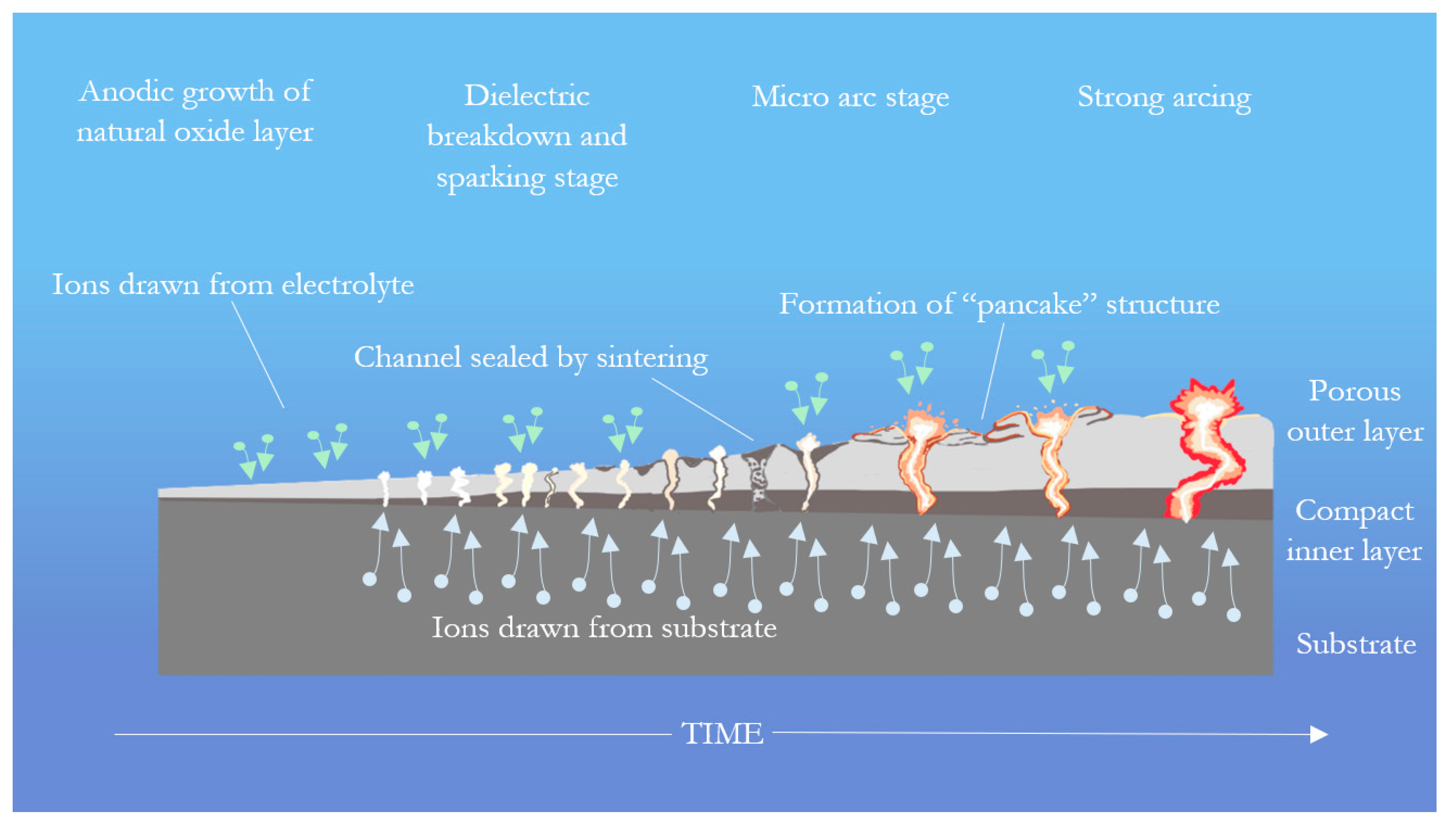
Figure 1. Overview of PEO process with time progressing to the right. Note the increasing size and decreasing number of discharges as the process continues. Figure produced by the author of this work.
Coatings 15 00592 g001
Figure 2. Progression of PEO discharge stages from sparking (left) to microarc (center) and finally strong arcing (right). Images taken by the author of this work.
Coatings 15 00592 g002
Figure 3. (1) Titanium sample in holder after PEO coating using setup from Figure 2. (2) Oxide layers produced on three samples after varying degrees of PEO processing. A: thin coating produced early in PEO process. B: well-developed coating that did not reach the strong arcing stage. C: sample subjected to strong arcing, with uneven coating and charred polymer residue from the sample holder damaged by arcing. Images taken by the author of this work.
Coatings 15 00592 g003
Figure 5. Summary of specific applications for modified PEO coatings.
Coatings 15 00592 g005
Table 1. PEO process parameter summary.
ParameterEffectReference
Current modeBipolar current lowers plasma temperatures, lowers porosity, improves corrosion resistance[49,50]
Higher negative current vs. positive reduces porosity
Current frequencyHigher frequencies reduce strong discharges, improving coating quality[47]
Short pulses result in better bonding but higher porosity
Processing timeLonger processing produces thicker coating, phase composition changes as coating develops[51]
Electrolyte compositionDifferent electrolyte components result in different oxide phases[52,53,54,55]
High electrolyte conductivity reduces operating voltages and improves efficiency, but process can fail if conductivity is too high[56]
Table 2. Conversion performance of PEO coatings for diesel desulfurization.
SubstrateCoatingContaminantConversion %Ref.
TiWO3 ± SiO2 ± TiO2Thiophene, 1%55[121]
Al-MnWO3 ± SiO2 ± −Al2O334
AlWO3 Al2O359
Al-MnWO3 Al2O346
Mn-WO2.9 Al2O347
Al2(WO4)3 Al2O345
WO3 Al2(WO4)351
TiZrO2, TiO2, CeOxThioanizole, 1%100[110]
Thiophene, 1%67
Thiophene, 0.5%61
Dibenzothiophene, 0.5%48
ZrO2, TiO2, CeOx, Ionic liquidThioanizole, 1%100
Thiophene, 1%89
Thiophene, 0.5%83
Dibenzothiophene, 0.5%65
TiTi, WO3Thiophene40[55]
TiO2, WO3, MnWO430
TiO2 (anatase), WO3, Na0.28WO3 *25
WO3, Zn0.3WO3 *82
Thioanizole100
Dibenzothiophene91
Diesel fuel97
WO3, Zn0.3WO3 *, Ionic liquidThiophene93
Thioanizole100
Dibenzothiophene98
Diesel fuel99.6
* Possible phase.
Table 3. Capacities of Li-ion batteries produced using PEO.
CoatingCapacityRef.
TiO2, SiO2700 μAh/cm2[56]
TiO2−x (self-doped)520 mAh/cm3[111]
TiO2, MoS2 sputtered560 mAh/g[58]
SnO2, TiO2200 mAh/g[59]
SnO2, TiO2, graphene482 mAh/g
SiO2, TiO2758 μAh/cm2[43]
SiO2, TiO2, PDMS1072 μAh/cm2
Table 4. Corrosion potential and current density reduction for different PEO treatments on magnesium.
PEO ModificationEcorr % ReductionIcorr % ReductionSource
Boiling water immersion35%76%[84]
Zirconia sol-gel14%92%
Gelatin-hydroxyapatite coating75%98%
Poly(L-lactide) spin coating14%99.87%[93]
MPTS sulfhydration5.8%99.96%[90]
PEGMA coating6.1%99.98%
Disclaimer/Publisher’s Note: The statements, opinions and data contained in all publications are solely those of the individual author(s) and contributor(s) and not of MDPI and/or the editor(s). MDPI and/or the editor(s) disclaim responsibility for any injury to people or property resulting from any ideas, methods, instructions or products referred to in the content.