Abstract
Mg–Zn–Mn-based biocomposites hold prospects as potential orthopedic material. The composition of these composites can be modulated, based on applications, by selective elemental alloying. Towards that, the addition of silicon (Si), hydroxyapatite (HA), or both is considered, followed by the consolidation method, such as spark plasma sintering (SPS). In this study, the micro-mechanical properties of Mg–Zn–Mn–(Si–HA) composites were investigated through the micro-pillar compression method. The effect of Si and HA incorporation on the mechanical characteristics and deformation mechanism was also elucidated. The microstructure of the composite presents porosity, together with different bioactive phases, such as Mg–Zn, CaMg, Mn–P, MgSi2, Mn–Si, Mn–CaO, CaMgSi, and Ca–Mn–O. Such porous structures were determined to facilitate cell growth when used as an implant, particularly for musculoskeletal-related disabilities. The yield stress (YS) and compressive stress of the Mg–Zn–Mn–Si–HA were about 1543 ± 99 MPa and 1825 ± 102 MPa, respectively. These values were about 5.8 and 4.8 times higher, respectively, than those of Mg–Zn–Mn–HA composites (266 ± 42 MPa and 380 ± 10 MPa, respectively), and the same was observed for the elastic modulus. Besides that, alloying with HA and Si alters the deformation mechanism from brittle (for Mg–Zn–Mn–Si composites) or ductile (for Mg–Zn–Mn–HA composites) to predominant ductile failure without compromising the attained mechanical properties.
1. Introduction
Biomedical devices and implants are ever increasing in demand due to their increased applications in orthopedics [1]. There are different types of biomaterials, such as metal-based, ceramic-based and polymer-based. Among them, metallic biomaterials are mostly used for load-bearing applications, such as relatively large implants (e.g., fixing plate, rod), screws, etc., for musculoskeletal-related disability treatment. High-end metallic biomaterials are titanium and titanium-based alloys, whereas chromium-based stainless steels are cheaper alternatives [2]. One common issue with the metallic biomaterials are their relatively higher Young’s modulus (110–200 GPa), which is several times higher (7–25 GPa) than that of human bones [3]. This mismatch in Young’s modulus causes stress shielding [4] during bone resorption. In addition, as these metallic materials are not biodegradable, post-healing removal of the fixtures is sometimes required and leads to additional surgical procedure [5,6]. Though reducing this discrepancy in Youngs’s modulus is important, this should not be achieved by sacrificing the strength of the implant. In such cases, pre-mature facture of the implants might occur, which is not desirable at all. In this regard, magnesium (Mg)-based composites can play a significant role as biomaterials [7]. Mg-based composites are biocompatible and biodegradable, and become an integral part of the system after post-healing. However, there are certain issues related to that, such as the strength of the Mg-based composites, and their corrosion resistance in the long run [8]. In regard to the degradation of Mg-based composites [9,10,11], ‘elemental alloying’ has been proven most effective [12]. In this process, elements of desired metallic powders are mixed and subjected to mechanical alloying by ball-milling, followed by consolidation, such as spark plasma sintering (SPS). The addition of Zn and/or Mn to Mg-based composites not only enhances their elasticity [13,14,15,16], but also increases the corrosion resistance in body fluids [17]. Further addition of hydroxyapatite (HA) leads to composites being reported as beneficial, such as calcium (Ca) in HA, which stimulates tissue growth and enhances the healing process [18]. This is particularly applicable for orthopedic applications of such materials as implants when used for musculoskeletal-related disability [19,20,21]. Furthermore, silicon (Si) incorporation can lead to a polygonal-shape Mg2Si intermetallic formation, which inhibits corrosion while maintaining low ductility and high strength [22]. Based on that, composites of Mg–Zn–Mn–(Si–HA) were successfully made, as reported by Sunil et al. [23] and Prakash et al. [24], by the SPS consolidation process. Besides the SPS process, elemental alloying has also proven useful in fabricating thermal sprayed hard composite coatings for wear and corrosion resistance applications [25,26].
Besides the mentioned Mg–Zn–Mn–(Si–HA) composites, there are a number of variations of such Mg-based composites, as described in the literature. Zheng et al. [27] described the fabrication of a Mg–Al–Zn-based composite by the SPS process that possesses 140 HV of micro-hardness and 442.3 MPa of compressive yield strength, together with an ultimate strength of 546 MPa, values which are reasonably greater compared to those of monolithic Mg alloys [27]. Fu et al. [28] processed a Mg–Zn–Mn–Ca-based composite by SPS with a tensile strength of 177–205 MPa, a yield strength of 58–69 MPa, and hardness of 49–53 HV. Gua et al. [29] described the feasibility of SPS to make a Mg-based composite by incorporating nano-HA. The addition of HA to Mg-based composites has proven beneficial for both resistance to corrosion and improvement in mechanical properties [30,31,32]. Rudinsky et al. [33] also reported the use of the SPS process towards the fabrication of a Al–Zn–Mg-based composite possessing a moderate level of flexural strength (659 MPa).
Recently, Prakash et al. reported the manufacture of Mg–Zn–Mn–(Si–HA), together with its characteristic mechanical (nanoindentation) properties [17] and in vitro bioactivity behavior [34]. In their study, the authors developed the composite through ‘multi-objective particle swarm optimization (MO-PSO) and the effect of mechanical alloying-assisted SPS process (MA-SPS) parameters on structural porosity, elastic modulus, and hardness of the composite were reported’ [24]. The composites show hardness of 97 HV, which is more than that of Mg-based alloys [35]. As can be seen from the literature survey, most of the published reports on such a material system focus on the fabrication, hardness investigation, and corrosion performances of such a material, without in-depth characterization of the mechanical properties at micro-scale. The current work was inspired by the further exploration of the micro-scale mechanical characteristics’ of such materials. The uniqueness of the current work includes in situ micro-pillar compression on Mg–Zn–Mn–(Si–HA) composite. Not only is this technique unique to the investigation of the micro-scale mechanical characteristics, but it also allows us to unveil the deformation mechanism at a micro scale, as successfully demonstrated for both coating [36,37] and bulk materials [38,39]. Moreover, the implants experience the compression nature of the forces in substantial applications [40]; thus, this micro-pillar compression better simulates the loading scenario.
The goal of the current work was to explore the mechanical characteristics of Mg–Zn–Mn–(Si–HA) at a micro-length scale. The effect of Si and/or HA on the mechanical properties of Mg–Zn–Mn-based composites was investigated. Towards that, micro-pillars were fabricated, and compression was conducted in situ inside the microscope. The respective deformation mode was discussed, based on the post-deformation morphology of the micro-pillars.
2. Materials and Methods
2.1. Composite Fabrication
Three different types of composites were fabricated, namely, Mg-Zn–Mn–Si (sample 1), Mg–Zn–Mn–HA (sample 2), and Mg–Zn–Mn–Si-HA (sample 3), as reported in Table 1 with their corresponding elemental compositions. The feedstock for mechanical alloying were ‘high purity (~99.9%) elemental powders of Mg, Mn, Zn, Si, and HA. The HA powder particles have an average particle size of 0.5 μm, with irregular shapes, and other powder particles exhibite an average particle size of 25 μm, with spherical morphology’ [24]. The powder of the required amount was weighed and transferred into a ball mill (model: Fritsch Pulverisette, Fritsch, Idar-Oberstein, Germany) made of stainless steel. The grinding media were balls of stainless steel with a diameter of 5 mm. The processes of mechanical alloying and sintering were as follows: “the powder mixture (300 gm) was mechanically alloyed for about 4 h at 300 rpm with a ball/powder ratio of 10:1. Stearic acid (0.1 gm) was used to prevent agglomeration and excessive cold welding of powders. The blended powders were preheated at 100 °C for 1 h, in the argon atmosphere, in order to remove the moisture. Then, the blended powder was consolidated by the SPS process (Sinter SPS-625, Fuji Electronic Industrial Co., Ltd., Fujimi, Japan). The SPS was carried out at a heating rate of 50 °C/min (for a holding time of 5 min) under vacuum. The sintering temperatures and pressure were 300 K and 30 MPa, respectively, in an argon atmosphere. A graphite die was used for the sintering and the solid compacts of 20 mm in diameter and 4 mm in thickness were synthesized. All the process parameters (alloying element, milling/alloying time, sintering temperature, and pressure on the porosity and elastic modulus based on L27 OA-based Taguchi method) employed in this study were optimized, as reported in previous publications” [24].

Table 1.
Types of composites prepared and investigated in this study.
2.2. Specimen Preparation
The as-fabricated cylindrical specimens were diced with a slow-cutting diamond saw and embedded in resin (Cito press-10, Struers, Ballerup, Denmark) for metallographic grinding and polishing. This was carried out with a Struers Tegrapol (Struers, Denmark) automatic metallographic polishing instrument. Final polishing was carried out in a colloidal silica medium. Both microstructural characterization and micro-pillar fabrication (as detailed in Section 3.2) were carried out with a field emission scanning electron microscope (SEM) equipped with a focused ion beam (FIB) (Helios Nanolab 600 FIB-SEM, Thermo-fisher Scientific, Waltham, MA, USA). Before SEM investigation, the samples were coated with carbon (sputter coating) to avoid the sample-charging issue during electron microscopy. The elemental analysis was carried out by energy-dispersive spectroscopy (EDS) using an Oxford Instruments EDS system (Oxford Instruments, Abingdon, UK) attached with a FIB-SEM. X-ray diffraction (XRD) investigation of the coating was carried out using monochromatic CuKα radiation XRD equipment (New D8 advance, Bruker, Karlsruhe, Karlsruhe, Germany).
2.3. In Situ Micro-Pillar Compression
The compression tests were carried out inside the FIB-SEM chamber. For that, the Hyistron PI-88 (Hyistron, Eden Prairie, MN, USA) indentation system was mounted on the SEM stage. The compression test was conducted in ‘displacement control mode’, and the (indenter) loading rate was 3 nm/s, which corresponds to a 10−3 s−1 strain rate. The morphology of the compressed micro-pillars was also examined by SEM. The output of the micro-pillar compression was the load–displacement graphs.
During the compression tests, the applied normal force (F) and corresponding changes in pillar length (Δl) were recorded during compression by a computer-controlled program, and were subsequently used to calculate the engineering stress and strain, according to Equations (1) and (2):
where σ is the engineering stress, F is the normal force, and A0 is the cross-sectional area of the pillar at 25% of its height from the top. As the pillars were slightly taper (<2°), the most likely deformation happened closer to the top surface [41].
where εE is the engineering strain, Δl is the change in pillar length, and l0 is the initial pillar length [42,43]. A minimum of 6 individual micro-pillars were compressed in each case, and the average values were reported, together with standard deviation, for statistical analysis.
3. Results and Discussion
3.1. Microstructure of the Composite
Mg-based composites were made via an ‘elemental alloying’ and SPS process. During the SPS, electrical sparks were observed among the powder particles’ contact area, and this thermal energy caused partial melting of the contact areas. Followed by the application of ‘uniaxial applied pressure’, consolidation of the powder occurred. The consolidation mechanism involves ‘mass transformation’ and ‘diffusion of powder particles’, which exhibits the characteristics of ‘neck formation’ [27]. In spite of the applied pressure and temperature, there is a limit of mass transformation and diffusion, which prohibits full densification of the structure and introduces porosities. This is evidenced in the SEM micrographs, as reported here. The morphology of the Mg–Zn–Mn–Si composite is depicted in Figure 1, together with its overall elemental composition. The SE image (Figure 1a) shows grain boundaries, among the Si particles and the surrounding matrix (white dotted lines), together with the presence of micro-pores, as indicated by the white arrows. More different phases were observed in the BSE image (Figure 1b). These phases include Mg-Zn, Mg-Si, Mn-O, Mg-Si-O, and others, as confirmed by the XRD investigation (Figure 4). The overall elemental analysis is shown in Figure 1c. The relatively higher carbon content is due to sputter-coating of the samples, to avoid charging issues, and hold true for the rest of the electron microscopy investigation.
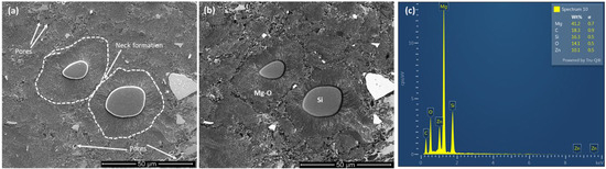
Figure 1.
SEM images of the Mg–Zn–Mn–Si specimen: (a) secondary electron (SE) image showing the morphology, (b) back-scattered electron image (BSE) showing the phase variation with corresponding elemental analysis (EDS) (c). The white arrows indicate the presence of pores and the dotted lines represent the grain boundaries among Si particles with the surrounding matrix.
Similarly, the morphology of the Mg–Zn–Mn–HA composite is depicted in Figure 2, together with its overall elemental composition. It is obvious that there was a prominent difference in the appearance of the microstructure, compared to Figure 1. The morphology indicates a substantial presence of porosities, as shown by the white arrows in Figure 2a, together with an elongated network pattern (Figure 2b). Based on the image analysis in Image J software, it was found that porosity ranges from 15% to 35%, with the average pore size in the range of 50 μm and above. Alloying of this composite with HA gives rise to various phases, such as Mn-CaO, β-TCP, CaMgZn and MgCaO, as confirmed through the XRD investigation (Figure 4).
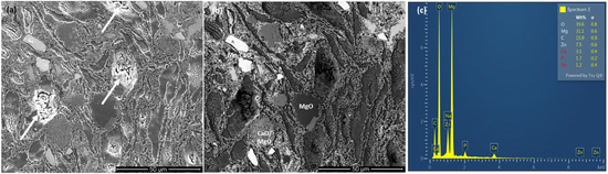
Figure 2.
SEM images of the Mg–Zn–Mn–HA specimen: (a) secondary electron (SE) image showing the morphology, (b) back-scattered electron image (BSE) showing the phase variation with corresponding elemental analysis (EDS) (c). The white arrows indicate the presence of pores.
The microstructure of the Mg–Zn–Mn–Si-HA specimen is shown in Figure 3, together with its overall elemental composition. Similar to the previous two specimens (Mg–Zn–Mn–Si and Mg–Zn–Mn–HA), the Mg–Zn–Mn–Si-HA composite also exhibits the presence of pores (indicated by arrows in Figure 3a) and different phases (Figure 3b). However, the extent of porosities was much subdued in comparison to that observed with the Mg–Zn–Mn–HA composite. In fact, this composite exhibits about 10%–15% porosity, with pore sizes of about 20–30 μm. Elemental mapping of the all the samples as conducted to confirm the distribution of the elements and it is reported in the Supplementary Materials.
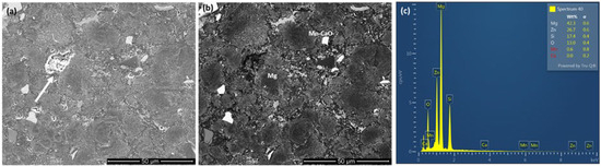
Figure 3.
SEM images of the Mg–Zn–Mn–Si-HA specimen: (a) secondary electron (SE) image showing the morphology, (b) back-scattered electron image (BSE) showing the phase variation with corresponding elemental analysis (EDS) (c). The white arrows indicate the presence of pores.
To further verify the presence of different phases in the martial systems investigated, XRD was carried out and the comparison of the spectra is shown in Figure 4. The alloying of simultaneous additions of HA and Si leads to the development of various phases, for example, MgSi2, Mn–CaO, Ca–Mn–O, Mn–Si, Mn–P, CaMg, Mg–Zn, CaMgSi and others, which collectively fall under the ‘HA’ phase. These findings are in line with the reports available in the literature [4,17,24,34] on a similar material system.
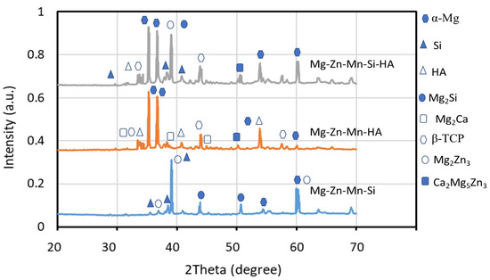
Figure 4.
XRD spectra of the composite materials investigated.
3.2. Micro-Pillar Fabrication on the Composites
The micro-pillars were fabricated on the surface of the specimens via ion beam milling. For this purpose, an FIB-SEM was employed. The pillar diameter was 3 μm and the height was 9 μm, leading to a 1:3 aspect ratio. A progressively lower current was used with final polishing, at 93 pA at 30 kV, to achieve a smooth pillar surface with a minimal ‘curtaining’ effect. Details of pillar fabrication can be found in the literature [44]. SEM micrographs of a series of micro-pillars made on Mg–Zn–Mn–Si-HA are shown in Figure 5a, together with higher-magnification images in Figure 5b–d. As confirmed from Figure 5b, the pillars were marginally taper (<2°) [45]. In addition, the existence of different phases and pores was also evident (pointed out by arrows).
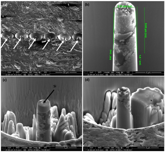
Figure 5.
FIB-prepared micro-pillars on the Mg–Zn–Mn–Si-HA specimen: (a) a series of micro-pillars each in the middle of a crater with close-up view (b–d) of different micro-pillars.
3.3. Compression of Micro-Pillars
As detailed in the experimental section, the ‘load–displacement curves obtained during micro-pillar compression’ were translated into the stress–strain curves, depicted in Figure 6. At first, there is a striking difference among the graphs. For the Mg–Zn–Mn-HA specimen, the stress level is quiet low, in a range of about under 400 MPa, with strain greater than 20%. However, the addition of either Si or both Si and HA increases the stress level considerably, i.e., in the range of 1400–1800 MPa; however, this happens at the expense of strain level. Both the Mg–Zn–Mn-Si and Mg–Zn–Mn-Si-HA composites fail under an 11% strain level. The Mg–Zn–Mn-HA composite demonstrates a predominantly ductile behavior as the strength of HA is under 400 MPa [41,44], and thus, it has limited contributions toward the enhancing of the mechanical properties. In comparison to that, the compressive strength of Si is in the range of 3200 MPa [46], and thus, offers a considerable increase in the stress levels when incorporated in the Mg–Zn–Mn matrix. The simultaneous inclusion of both Si and HA in the Mg–Zn–Mn matrix increases the strength of the Mg–Zn–Mn-Si-HA further, as evident from Figure 6. The key mechanical properties of the investigated composites were found from the stress–strain curves, and are tabulated in Table 2. The yield stress of the Mg–Zn–Mn-HA was 266 ± 42 MPa, whereas for the Mg–Zn–Mn-Si and Mg–Zn–Mn-Si-HA composites, it is 1339 ± 103 MPa and 1543 ± 99 MPa, respectively. This equates to an increase of about 5.8 times in the yield strength. It is also important to note, at the same time, that the yielding of the Mg–Zn–Mn-Si and Mg–Zn–Mn-Si-HA composites took place at about 5.45% and 6.5% strain, whereas for the Mg–Zn–Mn-HA composite, it was at about 2.5% strain. However, after the initial yield, the micro-pillars were able to withstand the continuing loading of >20% strain for Mg–Zn–Mn-HA. In contrast, Mg–Zn–Mn-Si and Mg–Zn–Mn-Si-HA can withstand up to 7.8% and 10% strain, respectively, before sudden collapse. Thus, it can be determined that the higher yield and compressive strength of the Mg–Zn–Mn-Si and Mg–Zn–Mn-Si-HA composites were attained at the expense of their relative ductility compared to that of Mg–Zn–Mn-HA composite. A similar tendency was noticed for the ultimate compressive strength, where there was an increase of about 4.8 times when both Si and HA were incorporated into the matrix compared to when HA alone was used. Similar levels of yield stress (< 200 MPa) were reported by Fu et al. [28] on the Mg–Zn–Mn–Ca composite consolidated by the SPS process.
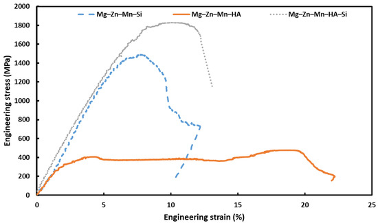
Figure 6.
Characteristic stress–strain graphs obtained on Mg–Zn–Mn-based composites upon in situ micro-pillar compression.
Table 2.
Mechanical characteristics of the currently investigated Mg–Zn–Mn-based composites.
3.4. Characteristics of the Distorted Micro-Pillars After Compression
As reported in the experimental section, the whole compression process was video-recorded with high-resolution SE imaging with SEM and was used for correlating the physical states of the micro-pillar at a given instance during compression. For example, the morphology of the micro-pillar on the Mg–Zn–Mn–HA composite during the middle and end of the compression experiment is shown in Figure 7. As evident, during the middle of the compression experiment, although the micro-pillar had already experienced fracture (marked with an arrow in Figure 7a), it continued to hold the loading until the end of the compression. At the end of the compression, upon retraction of the indenter, the micro-pillar still held together (Figure 7b) and experienced a kink (marked with a white arrow in Figure 7b), in addition to the fracture (mark with a black arrow). This observation is in line with the trend of the stress–strain curve for this composite, as shown in Figure 6, where the micro-pillar withstood the load until the end of the experiment with a >20% of strain level.
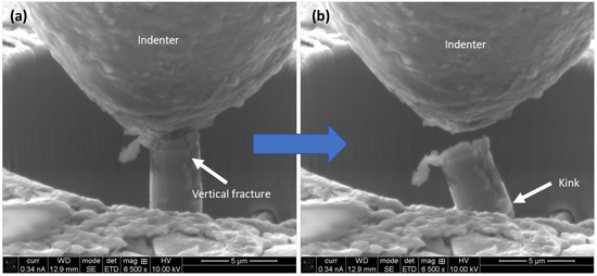
Figure 7.
Deformation evolution during micro-pillar compression on Mg–Zn–Mn–HA composite: (a) vertical fracture path as indicated by the arrow in the middle of the experiment and (b) vertical fracture path together with a kink at the completion of the experiment.
In comparison with the fracture morphology of Mg–Zn–Mn–HA composite, the deformation of the Mg–Zn–Mn–Si composite is completely different, as shown in Figure 8. Figure 8 shows the morphology of two different micro-pillars at the end of the compression. In this case, the micro-pillars snapped during the middle of the compression experiment, leading to the predominantly quasi-brittle nature of the fracture. The fracture line is different for different micro-pillars. Some of the micro-pillars exhibit a 0° fracture line (Figure 8a), whereas others exhibit stiff (60°) fracture lines (Figure 8b). Irrespective of the occurrence of the fracture line, the common scenarios were limited ductility, with a sudden collapse of the micro-pillar in the middle of the experiment. This is associated with the intrinsic mechanical properties of the Si, which is hard, brittle, has limited ductility, and is prone to fracture due to the presence of favorable crystal planes in the direction of maximum resolved shear planes [39].
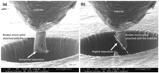
Figure 8.
Post-deformation view of the micro-pillars upon compression on the Mg–Zn–Mn–Si specimen. The arrow and dotted line indicate the fracture path. (a) The micro-pillars exhibit a 0° fracture line; (b) The micro-pillars exhibit a 60° fracture line.
The deformation morphology of the Mg–Zn–Mn–Si-HA composite is somewhat in between that of Mg–Zn–Mn–Si and Mg–Zn–Mn–HA composites, as shown in Figure 9. Figure 9a shows the deformation of the micro-pillar at about a 7% strain level, whereas Figure 9b shows the morphology at the end of compression at about 10% strain. Upon compression, a vertical fracture line develops (Figure 9a) along the length of the micro-pillar, similar to that of Mg–Zn–Mn–HA. However, as the loading continues (i.e., at higher loading level), the Si content of the micro-pillar experiences loading. Once the loading level exceeds the strength of that of Si, further fracturing takes place, which gives rise to the ‘Y’-shaped fracture path, as pointed out with white dotted lines in Figure 9b. Similar types of deformation mechanisms were reported by Juri et al. [47] on ceramic-based bio-materials for orthodontic applications.
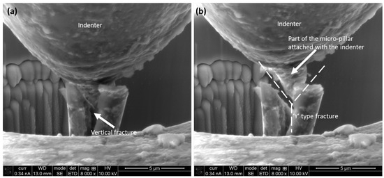
Figure 9.
Deformation evolution during micro-pillar compression on the Mg–Zn–Mn–Si-HA composite: (a) multiple vertical fracture path as indicated by the arrow in the middle of the experiment and (b) “Y”-shaped fracture path after the completion of the compression.
As evidenced by the experimental findings above, it is evident that simultaneous incorporations of Si and HA in the Mg–Zn–Mn matrix are more beneficial than the individual contributions of Si or HA alone. This is due to the fact that, as a hard and brittle material, Si provides the load-bearing aspect of the composite. On the other hand, as a relatively softer material, HA enhances the toughness of the composite. These facts also influence the deformation aspects of the composites. The composite containing only HA exhibits a predominant ductile fracture (Figure 7), whereas the composite containing only Si shows brittle fractures (Figure 8). Interestingly, the composite containing both Si and HA experiences the presence of both ductile and brittle fractures (Figure 9). The scientific reason behind such behavior was the interaction among different elements in the coating structure. HA is known to form good cohesion in the structure [48] and to be relatively low in hardness (679 MPa [49]). This allows the composite to flow under compression, which gives rise to its ductility. On the other that, Si is relatively hard (13 GPa hardness [50]) and inert in nature [51], which constrains its plastic flow [52], leading it to crumble under compressive loading. In the structures containing Si and HA, HA provides cohesion among the surrounding elements, whereas Si mostly plays the role of a reinforcing medium. Thus, both the ductile nature of HA and the reinforcing effect of Si were attained in the Mg–Zn–Mn-Si-HA coating.
4. Conclusions
The present work presents an insight into the mechanical characteristics of Mg–Zn–Mn–(Si–HA) under compression, along with its respective deformation mechanisms. The Mg–Zn–Mn composite matrix was mechanically tuned by the incorporation of HA and/or Si via element alloying and the SPS technique. The experimental outcomes and accompanying discussions lead to the following conclusions:
- The microstructure of the composite attained a porous network with the presence of various phases to fulfil the requirements of a biomaterial for prospective orthopedic applications.
- The yield and compressive strength of Mg–Zn–Mn–Si–HA (1543 ± 99 MPa and 1825 ± 102 MPa, respectively) are about 5.8 and 4.8 times higher, respectively, than those of Mg–Zn–Mn–HA (266 ± 42 MPa and 380 ± 10 MPa, respectively). This was attained due to the higher load-bearing capability of Si as an alloying element.
- The modulus of elasticity of Mg–Zn–Mn–Si–HA is reasonably lower (24 ± 1 MPa) to avoid stress-shielding issues in applications.
- The deformation mechanism of Mg–Zn–Mn–Si–HA is inherent in the ductile mode deformation aspect of Mg–Zn–Mn–HA and brittle mode deformation characteristics of the Mg–Zn–Mn–Si composite.
Thus, the newly designed Mg-Zn-Mn-Si-HA exhibits a promising microstructure, micro-mechanical properties, and a deformation aspect as a potential biomaterial. Future work may consider the development of controlled pore size, and distribution and fabrication of complex customized architectures for real-life applications. In addition, to address the complex nature of the forces/stresses in true prosthetic devices, multi-axis analyses of stress should be conducted.
Supplementary Materials
The following supporting information can be downloaded at: https://www.mdpi.com/article/10.3390/coatings15060655/s1, Figure S1: SE (a) and BSE (b) images of Mg–Zn–Mn–Si composite and corresponding elemental mapping: (c) Mg map, (d) Mn map, (e) O map, (f) Zn map, and (g) Si map; Figure S2: SE (a) and BSE (b) images of Mg–Zn–Mn–HA composite and corresponding elemental mapping: (c) Mg map, (d) Mn map, (e) O map, (f) Zn map, (g) Ca map and (h) P map; Figure S3: SE (a) and BSE (b) images of Mg–Zn–Mn–Si-HA composite and corresponding elemental mapping: (c) Mg map, (d) Mn map, (e) O map, (f) Zn map, (g) Ca map, (h) P map and (i) Si map.
Author Contributions
A.K.: Conceptualization, Writing, Experiment, Supervision; D.A.: Formal analysis, Validation, Resource, Writing—Review and Editing; S.S. and A.A.: Formal Analysis, Data Curation; A.D.: Formal Analysis, Data Curation, Experiments, Writing—Review and Editing; A.K.B.: Supervision, Writing—Review and Editing, Formal Analysis, Validation. All authors have read and agreed to the published version of the manuscript.
Funding
The authors extend their appreciation to the King Salman Center for Disability Research for funding this work through Research Group No. KSRG-2024-351.
Institutional Review Board Statement
Not applicable.
Informed Consent Statement
Not applicable.
Data Availability Statement
The raw/processed data used to produce the results will be made available by the corresponding author upon reasonable request.
Conflicts of Interest
Author Sayan Sarkar was employed by the company Intel Corporation. The remaining authors declare that the research was conducted in the absence of any commercial or financial relationships that could be construed as a potential conflict of interest.
References
- Natarajan, S. Biomimetic, Bioresponsive, and Bioactive Materials Edited by Matteo Santin and Gary J. Phillips; Taylor & Francis: Abingdon, UK, 2016. [Google Scholar]
- Nouri, A.; Wen, C. Stainless steels in orthopedics. In Structural Biomaterials; Elsevier: Amsterdam, The Netherlands, 2021; pp. 67–101. [Google Scholar]
- Alabort, E.; Tang, Y.; Barba, D.; Reed, R. Alloys-by-design: A low-modulus titanium alloy for additively manufactured biomedical implants. Acta Mater. 2022, 229, 117749. [Google Scholar] [CrossRef]
- Prakash, C.; Kansal, H.K.; Pabla, B.; Puri, S.; Aggarwal, A. Electric discharge machining—A potential choice for surface modification of metallic implants for orthopedic applications: A review. Proc. Inst. Mech. Eng. Part B J. Eng. Manuf. 2016, 230, 331–353. [Google Scholar] [CrossRef]
- Amukarimi, S.; Mozafari, M. Biodegradable magnesium-based biomaterials: An overview of challenges and opportunities. MedComm 2021, 2, 123–144. [Google Scholar] [CrossRef]
- Spoerke, E.D.; Murray, N.G.; Li, H.; Brinson, L.C.; Dunand, D.C.; Stupp, S.I. A bioactive titanium foam scaffold for bone repair. Acta Biomater. 2005, 1, 523–533. [Google Scholar] [CrossRef] [PubMed]
- Dutta, S.; Gupta, S.; Roy, M. Recent developments in magnesium metal–matrix composites for biomedical applications: A Review. ACS Biomater. Sci. Eng. 2020, 6, 4748–4773. [Google Scholar] [CrossRef]
- Song, G.; Atrens, A. Understanding Magnesium Corrosion—A Framework for Improved Alloy Performance. Adv. Eng. Mater. 2003, 5, 837–858. [Google Scholar] [CrossRef]
- Agarwal, S.; Curtin, J.; Duffy, B.; Jaiswal, S. Biodegradable magnesium alloys for orthopaedic applications: A review on corrosion, biocompatibility and surface modifications. Mater. Sci. Eng. C 2016, 68, 948–963. [Google Scholar] [CrossRef]
- Brooks, E.K.; Ehrensberger, M.T. Bio-corrosion of magnesium alloys for orthopaedic applications. J. Funct. Biomater. 2017, 8, 38. [Google Scholar] [CrossRef]
- Cho, D.H.; Lee, B.W.; Park, J.Y.; Cho, K.M.; Park, I.M. Effect of Mn addition on corrosion properties of biodegradable Mg-4Zn-0.5 Ca-xMn alloys. J. Alloys Compd. 2017, 695, 1166–1174. [Google Scholar] [CrossRef]
- Zhang, E.; Yin, D.; Xu, L.; Yang, L.; Yang, K. Microstructure, mechanical and corrosion properties and biocompatibility of Mg–Zn–Mn alloys for biomedical application. Mater. Sci. Eng. C 2009, 29, 987–993. [Google Scholar] [CrossRef]
- Radha, R.; Sreekanth, D. Insight of magnesium alloys and composites for orthopedic implant applications–a review. J. Magnes. Alloys 2017, 5, 286–312. [Google Scholar] [CrossRef]
- Huang, X.; Han, G.; Huang, W. T6 treatment and its effects on corrosion properties of an Mg–4Sn–4Zn–2Al Alloy. Materials 2018, 11, 628. [Google Scholar] [CrossRef] [PubMed]
- Gavras, S.; Buzolin, R.H.; Subroto, T.; Stark, A.; Tolnai, D. The effect of Zn content on the mechanical properties of Mg-4Nd-xZn Alloys (x = 0, 3, 5 and 8 wt.%). Materials 2018, 11, 1103. [Google Scholar] [CrossRef]
- Cheng, W.; Zhang, Y.; Ma, S.; Arthanari, S.; Cui, Z.; Wang, H.-x.; Wang, L. Tensile properties and corrosion behavior of extruded low-alloyed Mg–1Sn–1Al–1Zn alloy: The influence of microstructural characteristics. Materials 2018, 11, 1157. [Google Scholar] [CrossRef]
- Prakash, C.; Singh, S.; Gupta, M.K.; Mia, M.; Królczyk, G.; Khanna, N. Synthesis, characterization, corrosion resistance and in-vitro bioactivity behavior of biodegradable Mg–Zn–Mn–(Si–HA) composite for orthopaedic applications. Materials 2018, 11, 1602. [Google Scholar] [CrossRef]
- Li, Z.; Gu, X.; Lou, S.; Zheng, Y. The development of binary Mg–Ca alloys for use as biodegradable materials within bone. Biomaterials 2008, 29, 1329–1344. [Google Scholar] [CrossRef]
- Parande, G.; Manakari, V.; Prasadh, S.; Chauhan, D.; Rahate, S.; Wong, R.; Gupta, M. Strength retention, corrosion control and biocompatibility of Mg–Zn–Si/HA nanocomposites. J. Mech. Behav. Biomed. Mater. 2020, 103, 103584. [Google Scholar] [CrossRef]
- Predko, P.; Rajnovic, D.; Grilli, M.L.; Postolnyi, B.O.; Zemcenkovs, V.; Rijkuris, G.; Pole, E.; Lisnanskis, M. Promising methods for corrosion protection of magnesium alloys in the case of Mg-Al, Mg-Mn-Ce and Mg-Zn-Zr: A recent progress review. Metals 2021, 11, 1133. [Google Scholar] [CrossRef]
- Cho, D.H.; Avey, T.; Nam, K.H.; Dean, D.; Luo, A.A. In vitro and in vivo assessment of squeeze-cast Mg-Zn-Ca-Mn alloys for biomedical applications. Acta Biomater. 2022, 150, 442–455. [Google Scholar] [CrossRef]
- Ben-Hamu, G.; Eliezer, D.; Shin, K. The role of Si and Ca on new wrought Mg–Zn–Mn based alloy. Mater. Sci. Eng. A 2007, 447, 35–43. [Google Scholar] [CrossRef]
- Sunil, B.R.; Ganapathy, C.; Kumar, T.S.; Chakkingal, U. Processing and mechanical behavior of lamellar structured degradable magnesium–hydroxyapatite implants. J. Mech. Behav. Biomed. Mater. 2014, 40, 178–189. [Google Scholar] [CrossRef]
- Prakash, C.; Singh, S.; Pabla, B.; Sidhu, S.S.; Uddin, M. Bio-inspired low elastic biodegradable Mg-Zn-Mn-Si-HA alloy fabricated by spark plasma sintering. Mater. Manuf. Process. 2019, 34, 357–368. [Google Scholar] [CrossRef]
- Basak, A.K.; Celis, J.-P.; Vardavoulias, M.; Matteazzi, P. Effect of nanostructuring and Al alloying on friction and wear behaviour of thermal sprayed WC–Co coatings. Surf. Coat. Technol. 2012, 206, 3508–3516. [Google Scholar] [CrossRef]
- Basak, A.; Matteazzi, P.; Vardavoulias, M.; Celis, J.-P. Corrosion–wear behaviour of thermal sprayed nanostructured FeCu/WC–Co coatings. Wear 2006, 261, 1042–1050. [Google Scholar] [CrossRef]
- Zheng, B.; Ertorer, O.; Li, Y.; Zhou, Y.; Mathaudhu, S.N.; Tsao, C.Y.; Lavernia, E.J. High strength, nano-structured Mg–Al–Zn alloy. Mater. Sci. Eng. A 2011, 528, 2180–2191. [Google Scholar] [CrossRef]
- Fu, J.; Liu, K.; Du, W.; Wang, Z.; Li, S.; Du, X. Microstructure and mechanical properties of the as-cast Mg-Zn-Mn-Ca alloys. In Proceedings of IOP Conference Series: Materials Science and Engineering, Qingdao, China, 20–24 October 2016; IOP Publishing: Bristol, UK, 2017. [Google Scholar]
- Guo, P.; Cui, Z.; Yang, L.; Cheng, L.; Wang, W.; Xu, B. Preparation of Mg/Nano-HA Composites by Spark Plasma Sintering Method and Evaluation of Different Milling Time Effects on Their Microhardness, Corrosion Resistance, and Biocompatibility. Adv. Eng. Mater. 2017, 19, 1600294. [Google Scholar] [CrossRef]
- Sopyan, I.; Gunawan; Shah, Q.; Mel, M. Fabrication and sintering behavior of zinc-doped biphasic calcium phosphate bioceramics. Mater. Manuf. Process. 2016, 31, 713–718. [Google Scholar] [CrossRef]
- Sultana, N.; Mokhtar, M.; Hassan, M.I.; Jin, R.M.; Roozbahani, F.; Khan, T.H. Chitosan-based nanocomposite scaffolds for tissue engineering applications. Mater. Manuf. Process. 2015, 30, 273–278. [Google Scholar] [CrossRef]
- Du, H.; Liu, X.; Li, J.; Tao, P.; Jiang, J.; Sun, R.; Fan, Z. Use of spark plasma sintering for fabrication of porous titanium aluminide alloys from elemental powders. Mater. Manuf. Process. 2016, 31, 725–732. [Google Scholar] [CrossRef]
- Rudinsky, S.; Hendrickx, P.; Bishop, D.; Brochu, M. Spark plasma sintering and age hardening of an Al–Zn–Mg alloy powder blend. Mater. Sci. Eng. A 2016, 650, 129–138. [Google Scholar] [CrossRef]
- Prakash, C.; Singh, S.; Pabla, B.; Uddin, M. Synthesis, characterization, corrosion and bioactivity investigation of nano-HA coating deposited on biodegradable Mg-Zn-Mn alloy. Surf. Coat. Technol. 2018, 346, 9–18. [Google Scholar] [CrossRef]
- Singh, B.P.; Singh, R.; Mehta, J.; Prakash, C. Fabrication of biodegradable low elastic porous Mg-Zn-Mn-HA alloy by spark plasma sintering for orthopaedic applications. In Proceedings of IOP Conference Series: Materials Science and Engineering, Hyderabad, India, 3–4 July 2017; IOP Publishing: Bristol, UK, 2017. [Google Scholar]
- Kurdi, A.; Basak, A. Deformation of electrodeposited gradient Co/Sn multilayered coatings under micro-pillar compression. Eng. Fract. Mech. 2018, 204, 138–146. [Google Scholar] [CrossRef]
- Kurdi, A.; Tabbakh, T.; Alhazmi, H. Deformation of cold sprayed Ni-Sn coating under micro-pillar compression. Surf. Coat. Technol. 2020, 403, 126425. [Google Scholar] [CrossRef]
- Tabbakh, T.; Alshihri, S.; Basak, A.; Kurdi, A. Strength of a 3D printed Al 7068 alloy under micro-pillar compression. Met. Mater. Int. 2022, 28, 2706–2718. [Google Scholar] [CrossRef]
- Kurdi, A.; Basak, A. Micro-mechanical behaviour of selective laser melted Ti6Al4V under compression. Mater. Sci. Eng. A 2021, 826, 141975. [Google Scholar] [CrossRef]
- Arora, G.S.; Saxena, K.K. Critical review of Mg matrix composite for bio-implants through powder metallurgy. Mater. Today Proc. 2022, 57, 902–907. [Google Scholar] [CrossRef]
- Osuchukwu, O.A.; Salihi, A.; Abdullahi, I.; Abdulkareem, B.; Nwannenna, C.S. Synthesis techniques, characterization and mechanical properties of natural derived hydroxyapatite scaffolds for bone implants: A review. SN Appl. Sci. 2021, 3, 822. [Google Scholar] [CrossRef]
- Misra, A.; Hirth, J.; Hoagland, R. Length-scale-dependent deformation mechanisms in incoherent metallic multilayered composites. Acta Mater. 2005, 53, 4817–4824. [Google Scholar] [CrossRef]
- Basak, A.; Pramanik, A.; Prakash, C. Deformation and strengthening of SiC reinforced Al-MMCs during in-situ micro-pillar compression. Mater. Sci. Eng. A 2019, 763, 138141. [Google Scholar] [CrossRef]
- Martin, R.; Brown, P. Mechanical properties of hydroxyapatite formed at physiological temperature. J. Mater. Sci. Mater. Med. 1995, 6, 138–143. [Google Scholar] [CrossRef]
- Kurdi, A.; Degnah, A.; Tabbakh, T.; Alnaser, H.; Basak, A.K. Micro-Scale Deformation Aspects of Additively Fabricated Stainless Steel 316L under Compression. Materials 2024, 17, 439. [Google Scholar] [CrossRef] [PubMed]
- DelRio, F.W.; Cook, R.F.; Boyce, B.L. Fracture strength of micro- and nano-scale silicon components. Appl. Phys. Rev. 2015, 2, 021303. [Google Scholar] [CrossRef]
- Juri, A.Z.; Basak, A.K.; Yin, L. Failure mechanisms in in-situ SEM micropillar compressions of pre-crystallized and crystallized zirconia-containing lithium silicate glass-ceramics. Ceram. Int. 2023, 49, 27165–27175. [Google Scholar] [CrossRef]
- Jouda, N.S.; Essa, A.F. Preparation and study of the structural, physical and mechanical properties of hydroxyapatite nanocomposite. Mater. Today Proc. 2021, 47, 5999–6005. [Google Scholar] [CrossRef]
- Vahdat, A.; Ghasemi, B.; Yousefpour, M. Mechanical properties of the hydroxyapatite and magnetic nanocomposite of hydroxyapatite adsorbents. S. Afr. J. Chem. Eng. 2020, 33, 90–94. [Google Scholar] [CrossRef]
- Vandeperre, L.; Giuliani, F.; Lloyd, S.; Clegg, W. The hardness of silicon and germanium. Acta Mater. 2007, 55, 6307–6315. [Google Scholar] [CrossRef]
- Tanaka, H.; Kanayama, T. Inertness of SiC surfaces against Si atoms and clusters. Surf. Sci. 1999, 440, 252–258. [Google Scholar] [CrossRef]
- Rafferty, C.; Borucki, L.; Dutton, R. Plastic flow during thermal oxidation of silicon. Appl. Phys. Lett. 1989, 54, 1516–1518. [Google Scholar] [CrossRef]
Disclaimer/Publisher’s Note: The statements, opinions and data contained in all publications are solely those of the individual author(s) and contributor(s) and not of MDPI and/or the editor(s). MDPI and/or the editor(s) disclaim responsibility for any injury to people or property resulting from any ideas, methods, instructions or products referred to in the content. |
© 2025 by the authors. Licensee MDPI, Basel, Switzerland. This article is an open access article distributed under the terms and conditions of the Creative Commons Attribution (CC BY) license (https://creativecommons.org/licenses/by/4.0/).