Article

Initial Research on Ultrasonic Vibration-Assisted EDM for Processing Cylindrical Surfaces

1
Electronics and Electrical Department, East Asia University of Technology, Trinh Van Bo Street, Hanoi City 12000, Vietnam
2
Faculty of Mechanical Engineering, Thai Nguyen University of Technology, 3/2 Street, Tich Luong Ward, Thai Nguyen City 24000, Vietnam
3
National Research Institute of Mechanical Engineering, 04 Pham Van Dong, Ha Noi City 11309, Vietnam
*
Author to whom correspondence should be addressed.
Coatings 2025, 15(4), 463; https://doi.org/10.3390/coatings15040463
Submission received: 3 March 2025 / Revised: 3 April 2025 / Accepted: 9 April 2025 / Published: 14 April 2025

Abstract

:
Electrical discharge machining represents a non-conventional machining process, specifically designed for the effective fabrication of materials that are difficult to machine and for components with complex geometries. Many studies have been carried out that combine electrical discharge machining with the ultrasonic vibration of electrodes. Nevertheless, most of these investigations have concentrated on the processing of hole or cavity components. This document presents an experimental study focused on the design of an electrode holder for ultrasonic vibration electrical discharge machining, focusing on the machining of cylindrical surfaces. This study involved a two-stage design process for the electrode holder, aimed at determining the optimal length to achieve the maximal material removal rate and to ensure surface roughness. The novel aspect of this study is that it is the first to be published on the use of ultrasonic vibration in the electrical discharge machining process for processing cylindrical surfaces. Furthermore, splitting the electrode holder design process into two stages (theoretical calculation and experimental determination) made it possible to identify an electrode holder design for ultrasonic vibration electrical discharge machining that increased the MRR by 35.5% while maintaining SR values that were similar to those produced during the electrical discharge machining without ultrasonic vibration.

1. Introduction

Electrical discharge machining (EDM) is a modern machining method that offers several notable advantages, such as the ability to machine extremely hard conductive materials, create complex geometries with high precision and surface finish, and perform without mechanical cutting forces, making it suitable for thin, delicate, or high-accuracy components. However, one of the most significant drawbacks of EDM is its slow machining speed, as material removal occurs through individual electrical discharges with limited energy input. This results in extended machining time, especially for large parts or when high productivity is required. To overcome this limitation, EDM combined with ultrasonic vibration (UV) has been studied and applied. The ultrasonic vibration of the electrode enhances debris removal and stabilizes the discharge process, thereby increasing the material removal rate and reducing machining time, while also improving surface quality and reducing tool wear. As a result, EDM with ultrasonic assistance is considered a promising advancement that enhances the efficiency of electrical discharge machining in modern manufacturing.
M. Goiogana et al. [1] investigated the UVEDM process aimed at enhancing surface roughness during finishing operations. A copper rod tool electrode and a 1.2344 tempered alloy steel workpiece were utilized for this purpose. The findings indicated that the UVEDM process enhances the surface roughness and uniformity of machined surfaces during finishing EDM operations. Wang Y. et al. [2] detailed the material removal mechanism of UVEDM by utilizing heat transfer theory. A model for the microscopic removal volume of a single pulse in UVEDM has been established, taking into account the characteristics of the EDM removal mechanism and the influence of ultrasonic vibration energy. The process of generating micro-surface topography has been detailed, and an analysis of the influence of ultrasonic vibration on the machined surface has been conducted. Simulation calculations and experimental validations are conducted to verify the accuracy of the theoretical derivation. Takashi Endo et al. [3] provided the implementation of vibration-assisted machining in micro-EDM by utilizing PZT, which aimed to effectively remove debris from the gap between the tool electrode and the workpiece. The findings demonstrated that the implementation of vibration assistance enhances machining stability and leads to a significant decrease in machining time. A small square shaft was successfully fabricated using vibration-assisted micro-EDM to validate their experimental results. A. Schubert et al. [4] presented the current status of investigation into the micro-EDM process with UV assistance—which was directly applied to the workpiece and which indirectly applied high-intensity ultrasonic to the dielectric—in metallic materials as well as in the machining of electrically nonconductive ceramic materials. Utilizing ultrasonically aided micro-EDM can increase process speed by as much as 40%, allowing for the creation of bores with diameters under 90 µm and aspect ratios exceeding 40 in metallic materials.
A. Abdullah and M. R. Shabgard [5] investigated the influence of copper tool UV frequency on the EDM characteristics of cemented tungsten carbide (WC-Co). The effectiveness of the ultrasonic vibration of the tool in achieving a high MRR was observed to be greater when operating under conditions of low discharge currents and low pulse times, specifically in finishing regimes. The application of ultrasonic vibration increased both surface roughness and TWR. This study demonstrated that optimal conditions exist for the ultrasonic-assisted machining of cemented tungsten carbide. The study presented in [6] details the implementation of an electrical discharge and ultrasonic-assisted mechanical combined machining process that utilized a bronze-bonded diamond grinding wheel. The correlation between the machining effects and the parameters of the combined machining process has been analyzed. The results of the experiment demonstrated that the parameters of pulse width, pulse interval, peak current, ultrasonic amplitude, and open-circuit voltage have a significant impact on the processing effects. M. Iwai et al. [7] conducted an investigation into the EDM machinability of PCD utilizing a copper electrode that produces ultrasonic vibrations. This series of EDM experiments involved the selection of three types of ultrasonic vibration modes: axial vibration, flexural vibration, and complex vibration. The experimental results indicated that the efficiency of EDM increased to three times that of conventional EDM. Additionally, the results indicated that the effects were attributed to both the cavitation effect of the working fluid and the vibrational action of the electrode.
M. Goiogana et al. [8] accomplished a study on the UVEDM process aimed at enhancing machining efficiency and workpiece precision. The case study under consideration involved a horizontal blind hole characterized by an external diameter of 1 mm and an aspect ratio of 14. This study utilized a copper rod tool electrode in conjunction with a 1.2379 tempered alloy steel workpiece. The results indicated that the EDM process utilized an ultrasonic-assisted cryogenically cooled copper electrode while machining M2 grade high-speed steel. The parameters observed were MRR and SR. The controllable process variables included discharge current, pulse on-time, duty cycle, and gap voltage. An analysis has been conducted on the effect of process variables on EWR, MRR, and SR [9]. The MRR, EWR, and SR achieved in the EDM process using a normal electrode, a cryogenically cooled electrode, and an ultrasonic-assisted cryogenically cooled electrode have been analyzed and compared. The EWR and SR values were observed to be lower in the UVEDM process when compared to the conventional EDM, given the same set of process parameters. Meanwhile, the MRR was comparable to that of the conventional EDM process. P. Singh et al. [10] developed a novel ultrasonic-assisted micro-EDM setup, which was integrated into the existing ZNC-EDM machine. This study aims to experimentally investigate the influence of gap current (Ig), pulse on-time (Ton), pulse off-time (Toff), and ultrasonic power on MRR, TWR, and hole taper (Ta) in the context of ultrasonic-assisted hole sinking micro-EDM applied to titanium alloy workpieces. Experimental results indicate that the incorporation of ultrasonic vibration in hole sinking micro-EDM significantly influences MRR, TWR, and tool life (Ta).
H. Tong et al. [11] performed an investigation into the impact of utilizing gap servo control to assist workpiece vibration on the EDM performance of micro-structures. This study analyzes the process principle of the effects to elucidate our experimental results. It was noted that increased frequency vibration contributes to enhanced machining efficiency. Additionally, optimal machining results are achieved when the vibration amplitude is approximately equal to the discharge gap. J. Zhixin et al. [12] employed the UVPEDM technique to create holes in engineering ceramics. This study outlines the principle of UVPEDM. The UVPEDM technique generates pulse discharge through the UV of the tool electrode, as opposed to utilizing a specialized pulse generator found in conventional EDM methods. The UV output of the tool electrode functions as a method for flushing the gap. The experimental results confirm that this new technique effectively achieves a high MRR. A. Hirao et al. [13] conducted an investigation into the characteristics of EDM through the application of UV assistance to the tool electrode. The results indicated a significant increase in machining speed through the application of assisted UV on the tool electrode. The method demonstrated significant effectiveness in enhancing machining speed, even with a UV amplitude of 1 μm. The removal of machining wastes occurs effectively due to the tool electrode’s operation. Additionally, this method demonstrates high effectiveness in the machining of deeper holes. G. S. Prihandana et al. [14] conducted a study on UVEDM utilizing micro-MoS2 powder in dielectric fluid. A notable aspect of this work is the application of UV to the dielectric fluid. It has been observed that the incorporation of MoS2 micro-powder into dielectric fluid during UVEDM can lead to a substantial enhancement in the material removal rate and an improvement in surface quality.
The EDM process represents a highly accurate and efficient technique for the machining of hard, brittle materials and complex shapes. However, it exhibits notable limitations, especially regarding its low MRR, resulting in a time-consuming process. Furthermore, issues such as elevated tool wear, insufficient debris removal, and surface defects resulting from recast layers contribute to a decline in both efficiency and surface quality. UVEDM incorporates ultrasonic vibrations to effectively address these issues, facilitating debris removal, enhancing MRR, and stabilizing spark generation. UVEDM represents a significant advancement, addressing the limitations of traditional EDM and providing enhanced efficiency for high-demand applications.
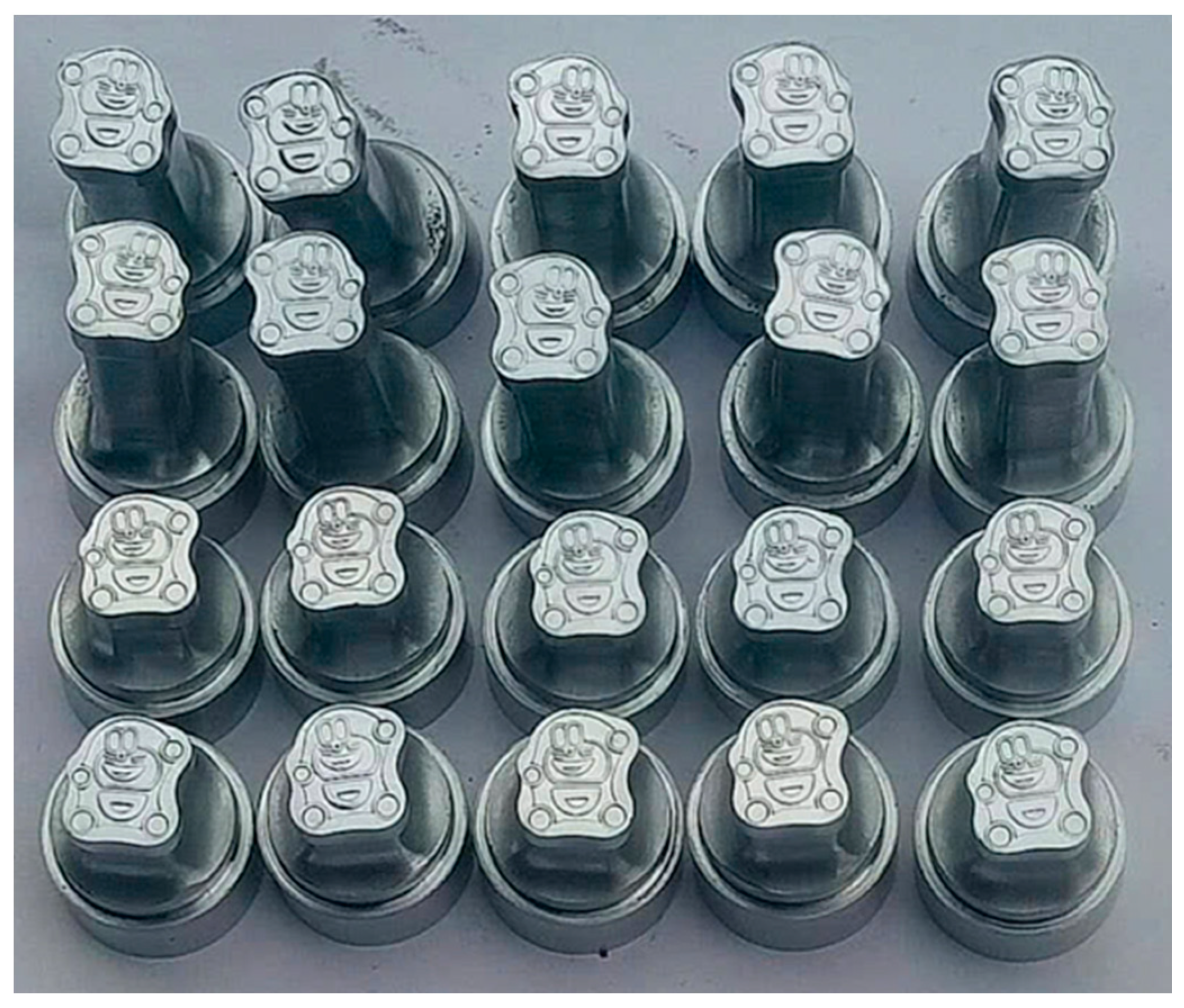
In the EDM method, the machining tool functions as the negative electrode (cathode), whereas the workpiece acts as the positive electrode (anode). The electrodes or tools are engineered with a specific geometry intended to generate features that align with the inverse configuration of the electrode, including applications such as plastic mold cavities, forging, or pressing dies. In practical applications, many parts display a cylindrical configuration, such as shaped tablet punches (Figure 1) and specialized punches intended for perforating steel plates, among others. To machine these components utilizing the EDM method, the electrode must feature a shaped cylindrical hole in its design. Recent studies have concentrated on EDM [15,16] and EDM that incorporates powder mixing [17,18], with a specific emphasis on outer cylindrical surfaces. No research has been conducted to date on the application of EDM machining for outer cylindrical surfaces using ultrasonic vibration.
The present paper outlines an experimental study aimed at the development of a vibrating head for UVEDM, intended for the machining of cylindrical surfaces. The electrode holder designed in this study aims to ensure the safe keeping of the electrode while also providing a means for delivering a dielectric solution. The optimal length of the electrode holder was determined to enhance the MRR while maintaining the required surface roughness.

2. Methodology

UV-assisted machining (UVAM) is an advanced machining method that employs mechanical vibrations at ultrasonic frequencies (20 kHz or higher) applied to either the machining tool or the workpiece. High-frequency mechanical vibrations are generated by a system consisting of an ultrasonic generator, a transducer, and a tool. This approach enhances both the efficiency and quality of the machining process. In the UVEDM process, UV can be applied to the workpiece [11], the electrode [5,12,13], or the dielectric [14]. In the usual EDM process, the tool, referred to as the electrode, maintains a stationary position while operating solely through translational movement. The implementation of ultrasonic vibration to the tool electrode is uncomplicated. Therefore, in this study, the electrodes, characterized by a hollow cylindrical shape, are subjected to UV application. In this case, the tool holder is suitable for machining components of different sizes, as long as they retain a consistent cylindrical geometry. Furthermore, as the tool remains stationary during EDM, the application of UV to the tool is straightforward.
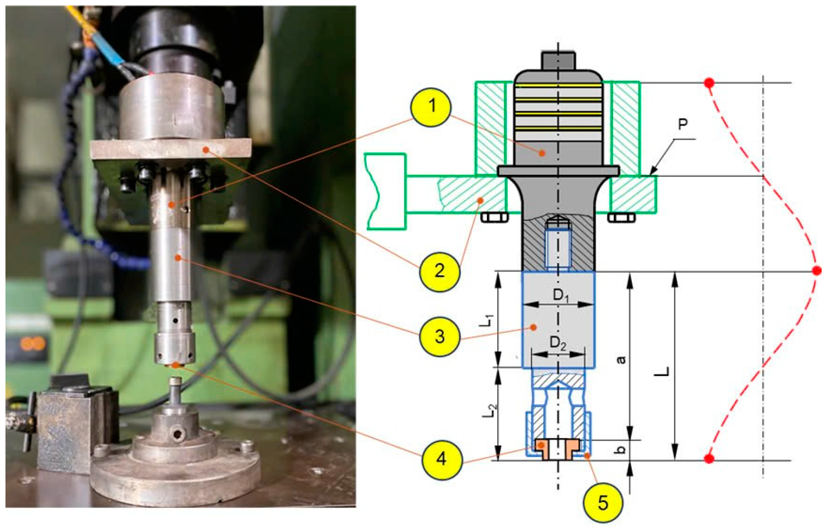
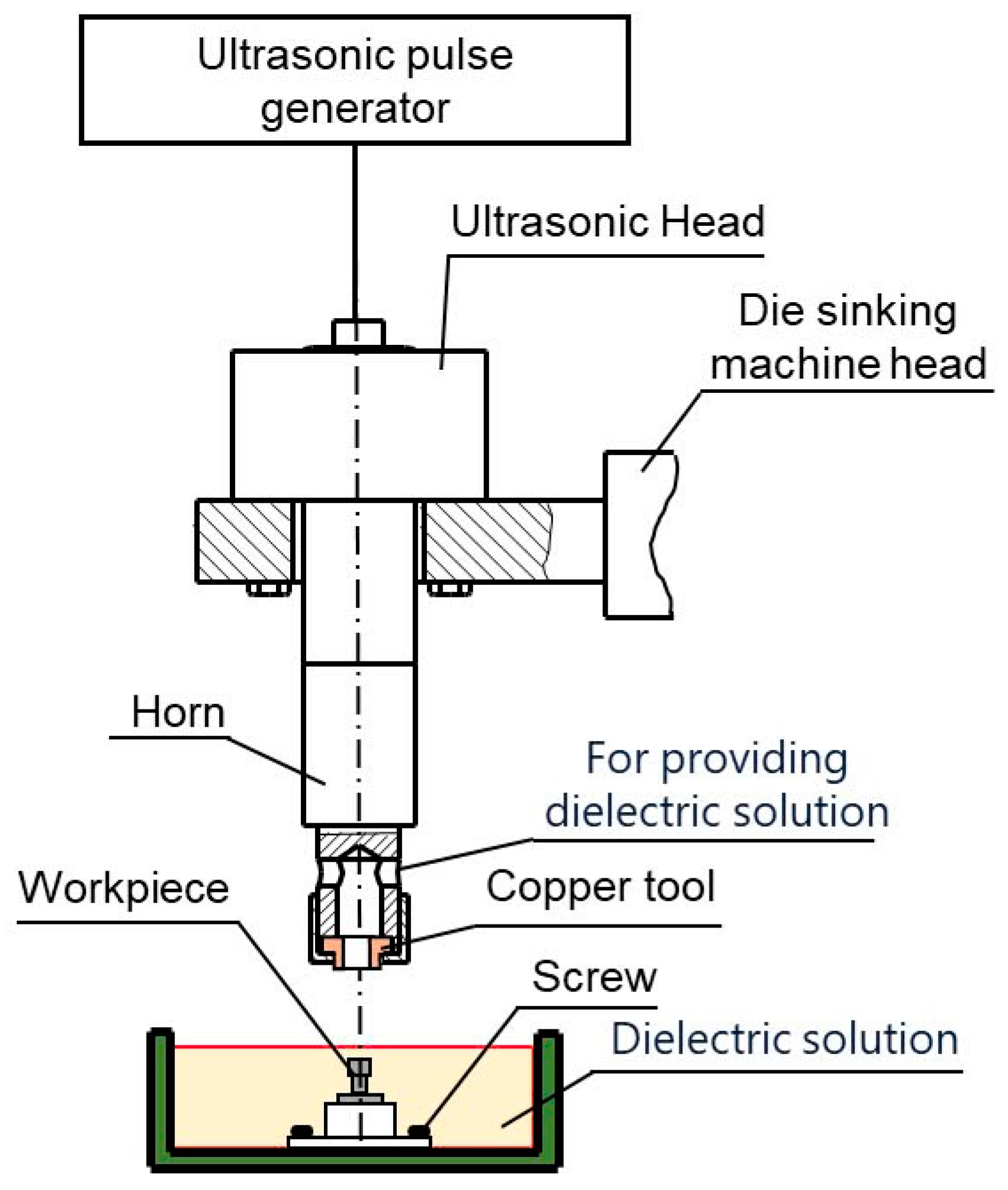
The vibration head was designed as illustrated in the schematic presented in Figure 2. Figure 3 presents the arrangement of the vibrating head along with the schematic representation of the ultrasonic vibration path. As illustrated in Figure 3, the transducer (1) is securely mounted on the head (2) of the die-sinking EDM machine at surface P, which corresponds to the zero vibration amplitude node. The horn (3) is directly connected to the transducer (1) via an internal thread in its upper section (diameter D1), ensuring a stable mechanical and vibrational connection. The lower section of the horn (diameter D2) features a central bore to accommodate the electrode (4) and an external thread for fastening the electrode using a nut (5).
The end face of the electrode (4), determined by the total length L = a + b, is the critical location that must coincide with the position of maximum vibration amplitude. Properly adjusting this length ensures that the ultrasonic energy is efficiently transmitted to the electrode face, enhancing material removal efficiency during the UVEDM process. To further facilitate the machining operation, the electrode holder (horn) is also equipped with lateral holes, allowing for the effective delivery of dielectric fluid into the discharge gap.
The ultrasonic vibration system used in this study consists of a transducer and a generator. Specifically, the ultrasonic transducer is model RPS-5020-4Z, manufactured in China, and the ultrasonic generator is model MPI WG-3000, produced in Switzerland. These components provide a stable vibration source at a nominal frequency of 20 ± 0.5 kHz with a maximum power of 2000 W from the transducer and 3000 W from the generator, supporting a wide operating frequency range between 15 and 100 kHz. These components were procured from manufacturers specializing in ultrasonic machining equipment, and their technical specifications are consistent with commercial standards for high-precision EDM applications. Table 1 presents the technical specifications of the ultrasonic transducer and generator.

3. Determining the Length of Electrode Holder

The calculation process for the electrode holder consists of two primary stages: (1) initial theoretical calculation and (2) experimental evaluation to identify the optimal value.

3.1. Theoretical Calculation

In this work, the materials selected for the horn and electrode are shown in Table 2. The horn is made from carbon steel C45, a medium-carbon steel commonly used in machine components due to its favorable strength, stiffness, and machinability. Its high Young’s modulus (195 GPa) and density (7850 kg/m3) enable the effective transmission of ultrasonic vibrations. The electrode is made from electrolytic copper C1100, which is more than 99.9% pure, providing excellent electrical and thermal conductivity, which is essential for stable spark discharges in EDM. The mechanical properties for C45 and copper C1100 were found based on standard values reported in MatWeb [16].
Based on the theory of wave propagation, the sound transmission speed is calculated according to the following formula [15]:
c = E / ρ
where c is the longitudinal wave velocity (m/s), E is the elastic modulus (GPa), ρ is the density (kg/m3), and f is the vibration frequency of the transducer (Hz).
Figure 3 indicates the primary dimensions of the electrode holder, including the horn (3), which consists of the following two parts: the first part with a diameter of D1 is attached to the ultrasonic transducer through a threaded connection, and the second part with a diameter of D2 is used to hold the electrode (4) by a threaded clamp (5).
The critical diameters are established based on two requirements: D1 = 41 (mm) (corresponding to the diameter of the transducer head) and D2 = 30 (mm) (in accordance with the electrode). The dimensions of the two shaft steps of the horn are initially determined based on wave propagation theory for solid rods with a constant cross-section. Due to the lack of a definitive formula for structures, including grooves, holes, and threaded joints, this estimate is merely preliminary and requires experimental validation.
Determining electrode holder length is done as follows:
According to wave propagation theory, the ultrasonic wavelength emitted from the amplifier head is λ, with the sound propagation velocity of the material denoted as c1 and the angular frequency of the ultrasonic oscillation represented by ω. The formula for determining the longitudinal displacement of material points at any position along the axis is defined as follows:
A x = A 1 c o s ω x c c o s ω t 0 x λ 4
Or
A x = A 2 c o s ω ( L x ) c c o s ω t λ / 4 x λ / 2
The gain of the horn is determined by the following:
A x = A 1 S 1 S 2
where S1 and S2 are the cross-sectional areas at the large and small end faces, respectively.
Determining the lengths of the cylindrical parts:
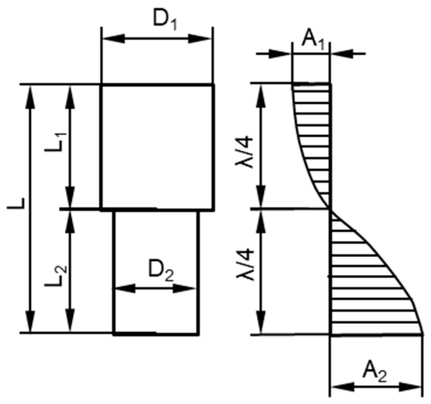
With the clamp material (C45), the sound transmission velocity is 4919.7 (m/s), and the length L1 of the cylindrical part D1 is calculated as follows (Figure 4):
L 1 = λ 4 = c 4 f = 4984 4.20 = 62.3   m m
With electrode material (copper C1100, sound velocity 3633 (m/s)), the average sound velocity with the collet is 4308.5 (m/s); therefore, the following is true:
L 2 = λ 4 = c 4 f = 4308.5 4.20 = 53.9   m m
The theoretical total length Lt of the preliminary electrode holder is shown as follows:
Lt = L1 + L2 = 62.3 + 53.9 = 116.2 mm

3.2. Experimental Determination of Optimum Length of Electrode Holder

The optimal electrode holder length is one that, when used for the EDM process, gives the largest MRR or the highest machining efficiency. In practice, the optimal electrode holder length does not coincide with the preliminary electrode holder length calculated above (L = 116.2 mm). This is because the actual electrode (Figure 4) deviates slightly from the electrode structure used for the length calculation (Figure 5). In addition, the use of threaded joints in the electrode holder also affects the vibration. Therefore, it is necessary to determine the optimal electrode length experimentally. This is conducted by keeping the L1 dimension as calculated above (L1 = 62.3 mm) and changing L2 by changing L using the following formula:
L = a + b
where the value of a is a constant and b is varied (i.e., L2 is varied) to find the optimal L.
A set of thirteen samples of electrode holders were manufactured with length L values distributed around the theoretical value Lt, and these were subsequently used in EDM experiments to evaluate machining performance.
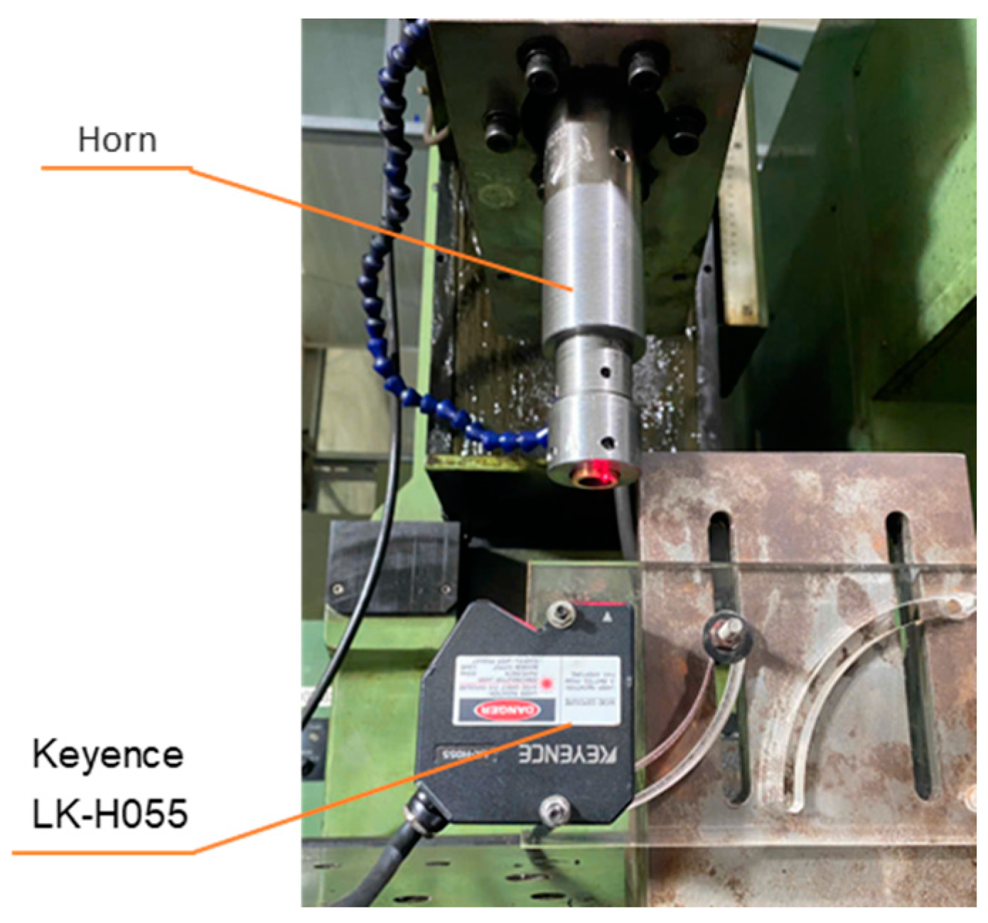
To verify the accuracy of the developed ultrasonic vibration amplitude meter, a comparative test was (Figure 5) conducted using the commercial laser displacement sensor Keyence LK-H055, Keyence Corporation, Japan. The vibration amplitude was measured at three different horn lengths, and the results are presented in Table 3 [18]. The maximum discrepancy between the two devices was 12.5%, while the smallest was 4.17%, demonstrating that the new device provides reasonably accurate measurements.
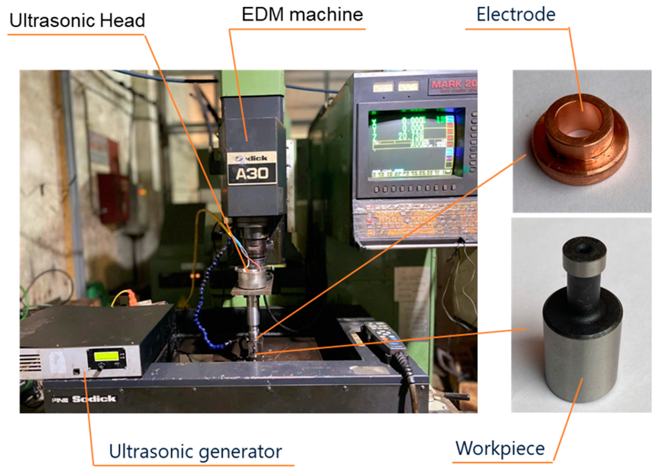
Figure 6 presents the experimental setup along with the associated machining parameters: Servo current: IP = 4 A; Servo voltage: vs. = 5 V; Pulse duration: Ton = 10 µs; Pulse interval: Toff = 10 µs.
After processing, the SR was assessed with a surface roughness tester (SV3100 measuring device, Mitutoyo, Japan, located at the KCS room of Machinery Spare Parts No.1 Joint Stock Company, Song Cong city, Viet Nam, and the MRR was determined using the following equation:
M R R = i = 1 n m s b i m s a i t s i
where msbi and msai represent the mass of sample i prior to and subsequent to machining (g); tsi is the processing time of sample i.
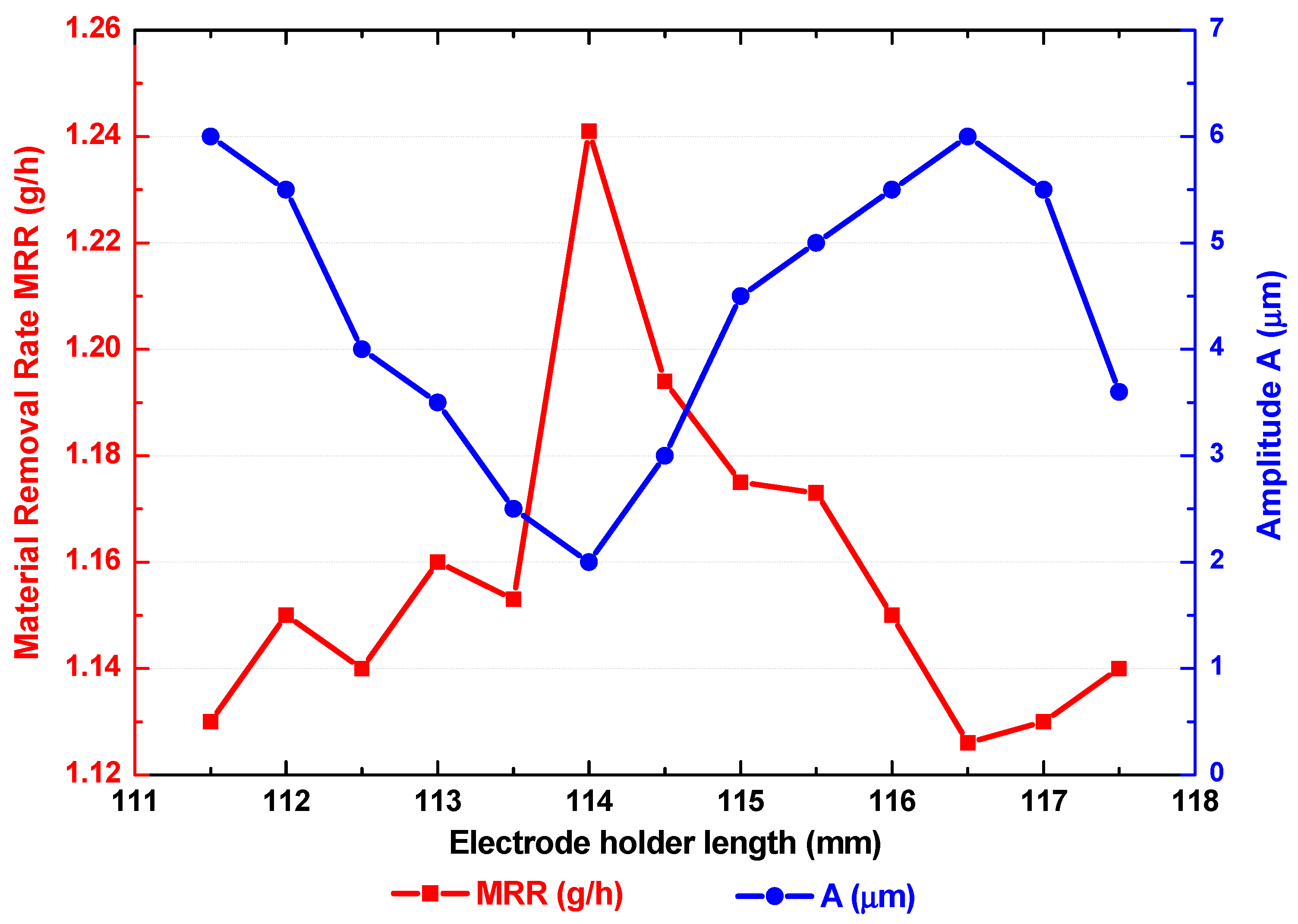
The experimental results are detailed as follows: in EDM without UV, the measured MRR is 1.1 (g/h), and the SR is 1.07 (µm). The amplitude and MRR data for machining with electrode holders of varying lengths (L) are presented in Table 3. Additionally, Figure 7 illustrates the relationship between L with ultrasonic vibration amplitude and MRR.
It was found that the maximum vibration amplitude in UVEDM occurred at L = 116.5 (mm) (Table 4), which closely aligns with the theoretical calculation value. Nevertheless, the use of the electrode holder exhibiting the greatest oscillation amplitude did not result in the highest MRR. According to Table 4, the maximum material removal rate (MRR) of 1.24 g/h was achieved when the vibration amplitude was only 2 µm (sample No. 8), corresponding to a total electrode holder length of 114.0 mm. This result indicates that the highest MRR did not coincide with the highest vibration amplitude (which occurred at L = 116.5 mm with amplitude = 6 µm) but rather with one of the lower amplitude values tested. This important observation suggests that optimizing MRR is not simply a matter of maximizing amplitude.
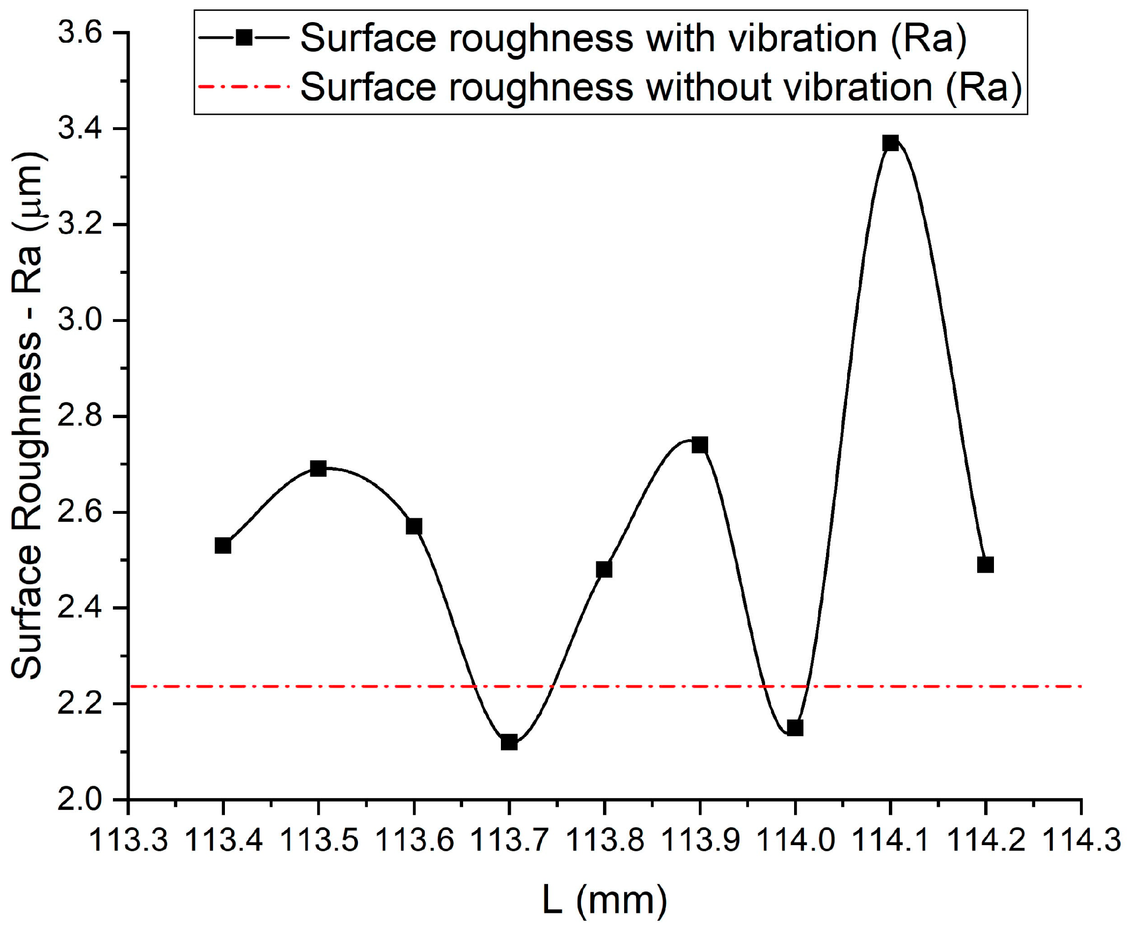
The relationship between electrode length L, vibration amplitude, and MRR is more clearly visualized in Figure 7. According to this graph, the optimal electrode holder length for maximizing MRR lies within the range from 113.4 mm to 114.2 mm, which corresponds to the electrode lengths from b = 11.9 mm to 12.7 mm. Consequently, further experiments were carried out using electrode lengths in that range with finer increments of 0.1 mm. The results of these tests, including both MRR and surface roughness (SR), are shown in Table 5, while Figure 8 and Figure 9 illustrate the trends of MRR and SR, respectively.
The following explanation supports the observed phenomenon: excessive vibration amplitude can reduce the discharge gap, leading to short circuits and unstable discharge behavior, which ultimately restricts the machining process. In contrast, an optimal vibration frequency and moderate amplitude induce vertical oscillations of the electrode, creating a pumping effect that enhances dielectric fluid circulation in the discharge gap and promotes efficient debris removal.
The optimal L value was established at 113.8 mm, providing a 35.5% enhancement in MRR relative to EDM without ultrasonic vibration. This verifies that UVEDM may substantially enhance the material removal rate. Nonetheless, as the primary aim of this work was to develop the electrode holder, the data acquired are merely preliminary. Consequently, additional research (presented in Section 4) is required to ascertain the optimal pulse mode for UVEDM.
The SR varied from 2.12 µm to 2.74 µm, closely approximating the SR value in EDM without vibration (2.24 µm). This roughness level falls within the semi-finishing surface roughness range, namely levels 5–7, which correspond to values from 1.25 µm to 5 µm.

3.3. Influence of Process Factors on MRR and SR During UVEDM Process

An experiment was conducted to explore the effects of input process factors in UVEDM on the material removal rate (MRR) and surface roughness (SR). The experimental setup used in this work is described in Figure 6. The experiment was performed utilizing a UVEDM machine, model A30 of Sodick, Japan and employing a copper electrode in conjunction with dielectric oil (Total Diel MS 7000, a product of TotalEnergies, France). The workpiece material is 90CrSi tool steel. Additionally, an electrode holder with an optimal value of L (113.8 mm, found in Section 3.1) was used. The selected input parameters include six values for Ton, ranging from 6 to 16 µs, six values for Toff, also ranging from 6 to 16 µs, six values for IP, spanning from 3 to 11 A, and four values for SV, varying from 3 to 9 V. Table 5 shows the input factors and experimental matrix.
The output results (MRR and SR) are presented in Table Additionally, Figure 10 and Figure 11 illustrate the relationship between the MRR and SR in relation to the input process parameters, respectively.
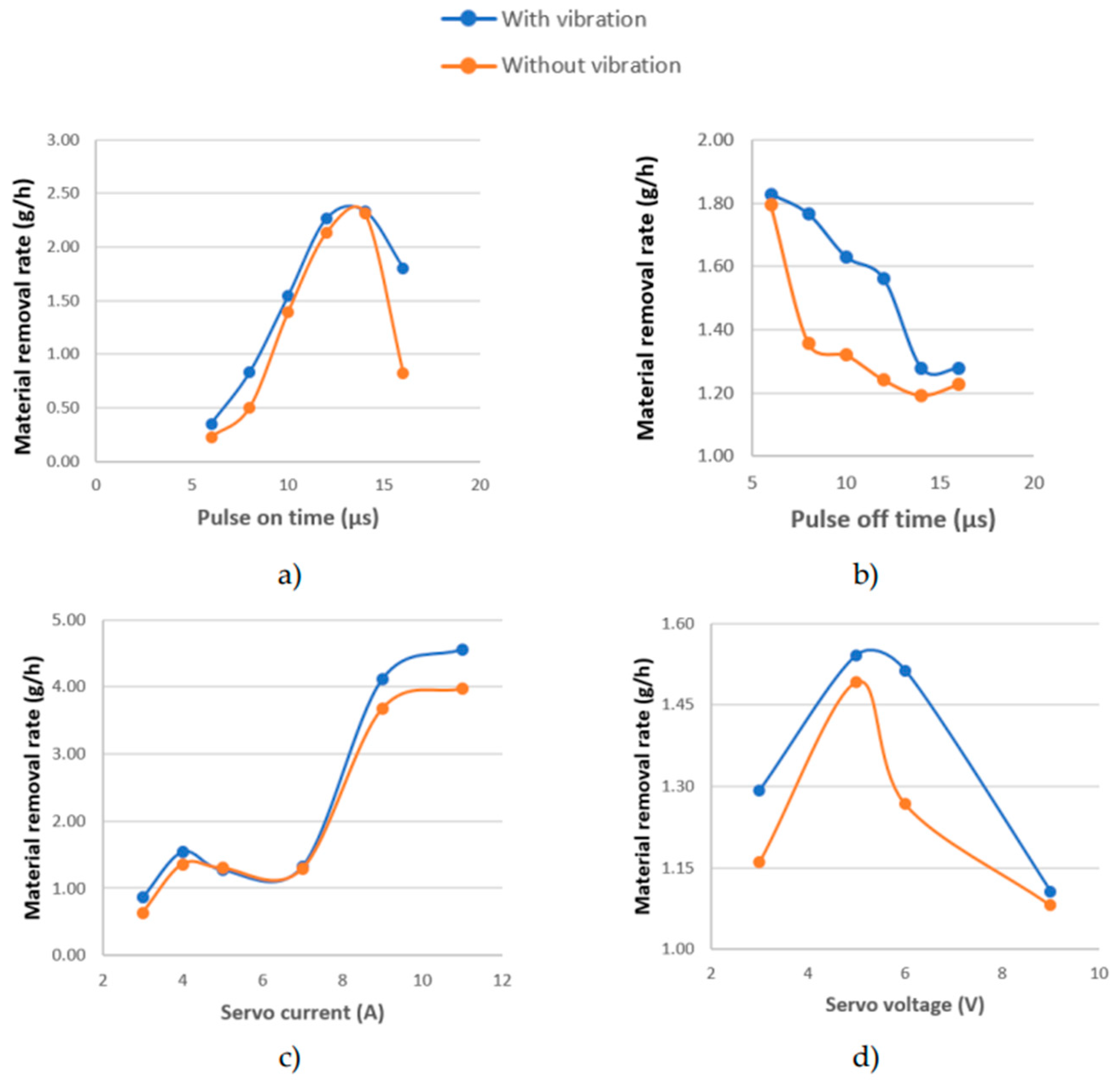
Table 6 and Figure 10 and Figure 11 demonstrate that nearly all machining modes of UVEDM display a significantly higher material removal rate (MRR) compared to conventional EDM without ultrasonic vibration assistance. UVEDM might enhance the MRR by as much as 119.51% in comparison to the absence of UV (Table 6). This demonstrates the primary advantage of UVEDM in comparison to traditional EDM methods.
Figure 10 demonstrates that the graphs representing the influence of process parameters on MRR during UVEDM exhibit the same configuration as those without UV. The influence of Ton on MRR is described in Figure 10a. Initially, as Ton is increased, the MRR exhibits an increase. This is attributed to the extended discharge duration, which facilitates improved plasma formation and enhances the material removal process. Exceeding the optimal level of Ton may result in excessive thermal effects, which can cause debris accumulation and a subsequent reduction in MRR. Consequently, an optimal value of Ton can be identified for MRR to achieve its maximum value. This observation aligns with the findings presented in reference [19]. Similar to non-UV machining, a rise in Toff results in a decrease in the MRR (Figure 10b), but an increase in IP leads to an increase in the MRR (Figure 10c). This observation is also noted in [20]. Figure 10d illustrates the correlation between SV and MRR. The SV influences discharge intensity and plasma formation. As SV rises from 3 V to 6 V, the MRR progressively increases due to the intensified electric field enabling dielectric ionization, hence enhancing material removal efficiency. However, if SV is excessively high, then the arc discharge may destabilize, resulting in a reduction in MRR. Consequently, an optimal value of SV exists to maximize MRR.
Figure 11 indicates that the SR values obtained post-UVEDM exhibit no apparent trend. Nonetheless, most UVEDM machining modes yield lower SR compared to machining without UV assistance; only seven test runs (experiments 6, 8, 10, 12, 13, 16, and 18) demonstrate higher SR values with UVEDM than without UV (Table 5). UVEDM may decrease the SR by up to 45,05% relative to the lack of presence of UV (Table 6). This illustrates the qualitative superiority of UVEDM compared to machining without UV.

4. Multi-Objective Optimization of Experimental Data Using Box–Behnken Design (BBD)

To further enhance the academic quality of this study, we conducted a multi-objective optimization using the Box–Behnken Design (BBD) method. This approach allows for the selection of the most optimal machining parameters by simultaneously considering two conflicting objectives, maximizing material removal rate (MRR) and minimizing surface roughness (SR), while also investigating the interaction effects between machining parameters.

4.1. Optimization Problem Definition

Ultrasonic vibration-assisted electrical discharge machining (UVEDM) is an advanced machining process that combines ultrasonic vibration with traditional EDM to enhance material removal rate (MRR) and improve surface quality. The machining process is influenced by several key input parameters, including ultrasonic vibration amplitude (A), pulse on-time (Ton), pulse off-time (Toff), peak current (IP), and supply voltage (SV).
The optimization challenge lies in balancing the trade-off between maximizing MRR and minimizing surface roughness (Ra).
This study aims to determine the optimal machining conditions that achieve a high MRR while maintaining a low Ra using the Box–Behnken Design (BBD) for experimental planning and employing both nonlinear regression and multi-objective decision-making techniques, specifically TOPSIS.

4.2. Experimental Planning with BBD

The Box–Behnken Design (BBD), a type of response surface methodology (RSM), is utilized to design the experiments systematically. The BBD approach provides an efficient way to explore the effects of multiple machining parameters without requiring a full factorial design, thus reducing the number of experimental trials while maintaining statistical validity.
The five machining parameters (A, Ton, Toff, IP, and SV) were considered as independent variables, each set at three levels (low, medium, and high). Details of the machine, electrode, and workpiece are consistent with the experimental setup described in Section 3.3. The response variables, MRR (g/h) and Ra (µm), were measured as output performance indicators. The total number of experimental runs was determined based on the BBD matrix. Table 7 describes the experimental plan).

4.3. Experimental Implementation and Data Collection

The experiments were conducted on a UVEDM setup with a tool electrode vibrating at an ultrasonic frequency. Workpiece material, dielectric medium, and machining conditions were kept consistent to minimize variability. After each machining trial, MRR was computed by measuring weight loss, while Ra was evaluated using a surface profilometer. These output results are presented in Table 7.
The collected data were analyzed to observe parameter interactions and identify significant factors influencing MRR and Ra. The results served as input for regression modeling and optimization.

4.4. Nonlinear Regression Model Construction and Data Analysis

To establish mathematical relationships between input parameters and response variables, a nonlinear regression model was developed using the following quadratic polynomial equation:
Y = β 0 + i = 1 n β i X i + i = 1 n β i i X i 2 + i = 1 n β i X i X j + ε
where Y represents MRR or Ra, Xi represents the input parameters, βi represents regression coefficients, and ϵ is the error term.
The regression model was trained using the least squares estimation approach, and model adequacy was verified using ANOVA. Results indicated that IP and A significantly influenced MRR, while Ra was more sensitive to variations in A and Toff. The model demonstrated high predictive accuracy (R2 > 90%), confirming its suitability for optimization. The regression coefficients for MRS (g/h) and Ra (µm) are described in Table 8 and Table 9, respectively.
  • Practical Significance of Regression Coefficients:
-
For MRR: Higher IP and SV increase material removal, while Toff negatively impacts MRR, suggesting that longer pulse off-times reduce efficiency.
-
For Ra: Higher IP and SV lead to rougher surfaces, while increasing A and Toff improves surface quality.
-
Quadratic terms suggest that extreme values of A, IP, and SV may have diminishing returns or negative effects.
  • Optimal Parameters for Balancing MRR and Ra:
Using the nonlinear regression model, the optimal parameters were determined to achieve the best trade-off between maximizing MRR and minimizing Ra, and these are shown as follows:
A = 1.1836 (μm); Ton = 12.8914 (µs); Toff = 11.2518 (µs); IP = 5.7919 (A); SV = 5.4418 (V).
  • Significance of the Optimal Parameters:
-
The low amplitude of ultrasonic vibration (A) ensures improved surface quality without significantly reducing MRR.
-
The moderate pulse on-time (Ton) and pulse off-time (Toff) maintain a balanced energy input, preventing excessive tool wear while ensuring stable machining.
-
The moderate peak current (IP) allows efficient material removal without excessive discharge energy that could increase surface roughness.
-
The moderate supply voltage (SV) helps stabilize the discharge process, ensuring a uniform surface finish.
-
These optimal conditions effectively maximize productivity while maintaining acceptable surface integrity, demonstrating the effectiveness of nonlinear regression in UVEDM process optimization.

4.5. Multi-Objective Optimization

To optimize both MRR and Ra simultaneously, in this work, a multi-objective optimization approach using nonlinear regression was implemented. The approach involved the following:

4.5.1. Defining the Objective Functions

Maximizing the MRR function obtained from regression:
M a x i m i z e   M R R = f A ,   T o n ,   T o f f ,   I P ,   S V
Minimizing the Ra function:
M i n i m i z e   M R R = g A ,   T o n ,   T o f f ,   I P ,   S V

4.5.2. Applying Constraints

Constraints were set based on practical machining limits and experimental data.
The search for optimal parameters was constrained within the tested parameter range to ensure realistic and feasible results.

4.5.3. Solving the Optimization Problem

A Pareto-based trade-off analysis was conducted to identify solutions that provide a balance between MRR and Ra.
The weighted sum method was applied to convert the multi-objective problem into a single objective function as follows:
O p t i m i z e   Z = w 1 · M R R w 2 · R a
where w1 and w2 are weight factors representing the relative importance of each objective.

4.5.4. Optimization Results

The following parameters were found to provide the best trade-off: A = 1.22 (μm), Ton = 12.5 (µs), Toff = 11.5 (µs), IP = 6.2 (A), and SV = 5.6 (V).
These values provide an improved MRR = 3.85 (g/h) while maintaining Ra = 3.76 (μm) within an acceptable range.
  • Significance of the Multi-objective Optimization Results
-
The optimization results align with practical requirements in UVEDM machining by offering a compromise between high material removal efficiency and good surface finish.
-
Using nonlinear regression for optimization allows for a more accurate prediction of machining performance compared to heuristic methods.
-
The obtained results serve as a guideline for selecting machining parameters to achieve the desired balance between productivity and quality.
-
The combination of regression modeling with multi-objective optimization offers a systematic approach that can be extended to other advanced machining processes.

4.5.5. Evaluation of Multi-Objective Optimization Results Using Nonlinear Regression

While an experimental validation with a newly designed horn for UVEDM would provide the highest level of accuracy, it requires significant resources and setup modifications, making it a future research goal. In the meantime, applying an MCDM method allows for an objective comparison, validating the efficiency of the nonlinear regression results before committing to physical trials.
Multi-criteria decision-making (MCDM) techniques are widely used in engineering optimization where multiple conflicting objectives must be balanced. In the context of UVEDM, MRR and Ra present opposing goals—higher MRR is desirable for productivity, while lower Ra ensures better surface quality. While nonlinear regression provides an optimized parameter set, its evaluation requires an additional validation method to assess trade-offs objectively.
In this work, TOPSIS was chosen among MCDM methods for the evaluation of multi-objective optimization results using nonlinear regression. The TOPSIS method (Technique for Order of Preference by Similarity to Ideal Solution) was proposed by C.L. Hwang and K. Yoon in 1981 [21]. This is one of the influential multi-criteria decision-making (MCDM) methods and is widely used in many fields, such as engineering, management, finance, and logistics. It was selected for this evaluation due to the following advantages:
-
Closeness to the Ideal Solution: TOPSIS ranks alternatives based on their Euclidean distance to an ideal best and worst solution, ensuring that the selected parameters align well with practical machining goals.
-
Straightforward Computation: Unlike genetic algorithms or fuzzy logic approaches, TOPSIS is computationally efficient and can be directly applied to experimental data.
-
Quantitative Ranking: It provides a clear ranking of parameter sets, helping to compare regression-based optimization with experimental outcomes.
The fundamentals of TOPSIS were presented in detail in [21] as well as many other scientific documents. TOPSIS ranks solutions by the following:
-
Normalizing the decision matrix to ensure comparability across different scales;
Weighting the criteria to reflect their importance;
-
Determining the ideal best and worst solutions based on the most and least desirable values for each parameter;
-
Calculating the Euclidean distance of each alternative from the ideal best and worst solutions;
-
Computing a TOPSIS score where the best solution is the one closest to the ideal best and farthest from the ideal worst.
Using the experimental dataset and applying the TOPSIS method, Table 10 presents several calculated results by the TOPSIS technique, and from these, it was found that option 12 is the best. In addition, using Table 10 and Table 11, the following machining parameters were found to be optimal: A = 1.15 (μm), Ton = 12 (µs), Toff = 8 (µs), IP = 5 (A), and SV = 3 (V).
  • Evaluation of the Optimization Methods:
Table 11 clearly shows the following predicted values of MRR and Ra for both methods:
-
Nonlinear regression yields the highest predicted MRR (3.85 g/h) while maintaining a relatively low Ra (3.76 µm).
-
TOPSIS, though simpler to apply based on experimental data, results in a slightly lower MRR (3.546 g/h) and a similar Ra (3.770 µm).
-
These differences demonstrate that the nonlinear regression method provides a more favorable balance between the two objectives. The results validate the use of nonlinear modeling combined with multi-objective optimization strategies to derive practical and effective UVEDM parameter settings.
-
TOPSIS favors a lower peak current (IP = 5 A) and supply voltage (SV = 3 V), which contribute to a reduced energy input during machining.
-
Nonlinear regression finds a more balanced setting (IP = 6.2 A, SV = 5.6 V), ensuring a high MRR while keeping Ra within acceptable limits.
-
TOPSIS and nonlinear regression produce similar recommendations for Ton, but differ significantly in Toff, suggesting that pulse off-time is a key trade-off factor in UVEDM optimization.
5. Conclusions

The article presents an experimental study aimed at the design and fabrication of an electrode holder specifically for UVEDM, with a focus on the machining processes applicable to cylindrical surfaces. The design of the electrode holder in this study was carried out in two phases to determine the optimal length required for maximizing the MRR. The following conclusions can be drawn from the study’s findings:
-
Experimental methods can be employed to ascertain the optimal dimensions of the electrode holder for UVEDM.
-
A two-step design process for the electrode holder (theoretical calculation and experimental determination) minimizes the number of required experiments, thereby decreasing both the time and cost associated with the design.
-
The proposed electrode holder for UVEDM improves the MRR by 119.51%, while the SR values remain comparable to those obtained without UV during the machining process.
-
The effect of input parameters on MRR and SR during the UVEDM process was investigated.
-
This study successfully optimized UVEDM parameters using BBK, nonlinear regression, and TOPSIS. The key findings are shown as follows:
-
Nonlinear regression yielded a well-balanced machining setting that optimized both MRR and Ra.
-
TOPSIS provided an alternative setting favoring high MRR, though at the cost of increased surface roughness.
-
A hybrid approach combining both methods could offer a robust solution for real-world applications.
Future work includes validating the models with additional experiments and exploring advanced multi-objective optimization techniques such as genetic algorithms or machine learning-based models.

Author Contributions

The initial concept was presented by T.-P.-T.T. and N.-P.V., and each author provided a discussion on it. T.-P.-T.T. conducted the experimental work with assistance from V.-T.D., T.-Q.L., T.-T.D. and A.-T.L. The authors conducted the design of the simulation, performed the analysis of the experimental data, and evaluated the results obtained from the simulation. N.-P.V. and T.-P.-T.T. engaged in a collaborative effort to produce the manuscript. All authors have read and agreed to the published version of the manuscript.

Funding

This work received funding from Project B2023-TNA-19, which is supported by the Ministry of Education and Training of Vietnam (MOET).

Institutional Review Board Statement

Not applicable.

Informed Consent Statement

Not applicable.

Data Availability Statement

The original contributions presented in this study are included in the article. Further inquiries can be directed to the corresponding author.

Conflicts of Interest

The authors declare no conflict of interest.

Abbreviations

EDMElectrical discharge machining
MRRMaterial removal rate (g/h)
IPPulse current (A)
TonPulse on-time (μs)
ToffPulse off-time (μs)
SVServo voltage (A)
SRSurface roughness (μm)
TWRTool wear ratio
UVUltrasonic vibration
UVEDMUltrasonic vibration-assisted electrical discharge machining

References

  1. Goiogana, M.; Sarasua, J.A.; Ramos, J.M.; Echavarri, L.; Cascón, I. Pulsed ultrasonic assisted electrical discharge machining for finishing operations. Int. J. Mach. Tools Manuf. 2016, 109, 87–93. [Google Scholar] [CrossRef]
  2. Wang, Y.; Liu, Z.; Shi, J.; Dong, Y.; Yang, S.; Zhang, X.; Lin, B. Analysis of material removal and surface generation mechanism of ultrasonic vibration–assisted EDM. Int. J. Adv. Manuf. Technol. 2020, 110, 177–189. [Google Scholar] [CrossRef]
  3. Endo, T.; Tsujimoto, T.; Mitsui, K. Study of vibration-assisted micro-EDM—The effect of vibration on machining time and stability of discharge. Precis. Eng. 2008, 32, 269–277. [Google Scholar] [CrossRef]
  4. Schubert, A.; Zeidler, H.; Hackert-Oschätzchen, M.; Schneider, J.; Hahn, M. Enhancing micro-EDM using ultrasonic vibration and approaches for machining of nonconducting ceramics. Stroj. Vestn.-J. Mech. Eng. 2013, 59, 156–164. [Google Scholar] [CrossRef]
  5. Abdullah, A.; Shabgard, M.R. Effect of ultrasonic vibration of tool on electrical discharge machining of cemented tungsten carbide (WC-Co). Int. J. Adv. Manuf. Technol. 2008, 38, 1137–1147. [Google Scholar] [CrossRef]
  6. Zhang, Q.; Li, J.; Cai, Y.; Wang, H.; Wang, X. Study on electrical discharge and ultrasonic assisted mechanical combined machining of polycrystalline diamond. Procedia CIRP 2013, 6, 589–593. [Google Scholar]
  7. Iwai, M.; Ninomiya, S.; Suzuki, K. Improvement of EDM properties of PCD with electrode vibrated by ultrasonic transducer. Procedia CIRP 2013, 6, 146–150. [Google Scholar] [CrossRef]
  8. Goiogana, M.; Sarasua, J.; Ramos, J. Ultrasonic assisted electrical discharge machining for high aspect ratio blind holes. Procedia CIRP 2018, 68, 81–85. [Google Scholar] [CrossRef]
  9. Srivastava, V.; Pandey, P.M. Effect of process parameters on the performance of EDM process with ultrasonic assisted cryogenically cooled electrode. J. Manuf. Process. 2012, 14, 393–402. [Google Scholar] [CrossRef]
  10. Singh, P.; Yadava, V.; Narayan, A. Parametric study of ultrasonic-assisted hole sinking micro-EDM of titanium alloy. Int. J. Adv. Manuf. Technol. 2018, 94, 2551–2562. [Google Scholar] [CrossRef]
  11. Tong, H.; Li, Y.; Wang, Y. Experimental research on vibration assisted EDM of micro-structures with non-circular cross-section. J. Mater. Process. Technol. 2008, 208, 289–298. [Google Scholar] [CrossRef]
  12. Jia, Z.; Zhang, J.; Ai, X. Ultrasonic vibration pulse electro-discharge machining of holes in engineering ceramics. J. Mater. Process. Technol. 1995, 53, 811–816. [Google Scholar]
  13. Hirao, A.; Gotoh, H.; Tani, T. Some effects on EDM characteristics by assisted ultrasonic vibration of the tool electrode. Procedia CIRP 2018, 68, 76–80. [Google Scholar] [CrossRef]
  14. Prihandana, G.S.; Mahardika, M.; Hamdi, M.; Wong, Y.S.; Mitsui, K. Effect of micro-powder suspension and ultrasonic vibration of dielectric fluid in micro-EDM processes—Taguchi approach. Int. J. Mach. Tools Manuf. 2009, 49, 1035–1041. [Google Scholar] [CrossRef]
  15. Ensminger, D.; Stulen, F.B. Ultrasonics: Data, Equations and Their Practical Uses; CRC Press: Boca Raton, FL, USA, 2008. [Google Scholar]
  16. MatWeb. AISI 1045 Steel, Normalized, 50 mm Round. Available online: https://www.matweb.com/search/DataSheet.aspx?MatGUID=1d7344b74e654bd9a06451bfb5f8903f (accessed on 2 March 2025).
  17. Yu, J.W.; Dabrowski, L.; Yin, S.H.; Lechniak, Z. Productivity of EDM process assisted by ultrasonic waves. Solid State Phenom. 2011, 175, 157–160. [Google Scholar] [CrossRef]
  18. Tam, D.T.; Minh, L.D.; Pi, V.N.; Quy, L.T.; Thao, T.T.P. Design and manufacturing of ultrasonic vibration amplitude measuring device using digital micrometer. Vietnam. Mech. Eng. J. 2025, 326. [Google Scholar]
  19. Shabgard, M.; Sadizadeh, B.; Kakoulvand, H. The effect of ultrasonic vibration of workpiece in electrical discharge machining of AISIH13 tool steel. Int. J. Mech. Mechatron. Eng. 2009, 3, 404–408. [Google Scholar]
  20. Chen, Y.; Mahdivian, S. Analysis of electro-discharge machining process and its comparison with experiments. J. Mater. Process. Technol. 2000, 104, 150–157. [Google Scholar] [CrossRef]
  21. Hwang, C.L.; Yoon, K. Multiple Attribute Decision Making: Methods and Applications; Springer: Berlin/Heidelberg, Germany, 1981. [Google Scholar]
Figure 1. Shaped tablet punches.
Coatings 15 00463 g001
Figure 2. Ultrasonic vibration head.
Coatings 15 00463 g002
Figure 3. The vibrating head design: (1) ultrasonic transducer; (2) die sinking machine head; (3) horn; (4) electrode.; (5) nut.
Coatings 15 00463 g003
Figure 4. Diagram of the calculation of horn’s length.
Coatings 15 00463 g004
Figure 5. Experimental setup for measuring the amplitude.
Coatings 15 00463 g005
Figure 6. Experimental setup for UVEDM.
Coatings 15 00463 g006
Figure 7. Relationship between L and amplitude and MRR.
Coatings 15 00463 g007
Figure 8. Relationship between L and the material removal rate.
Coatings 15 00463 g008
Figure 9. Relationship between L and surface roughness.
Coatings 15 00463 g009
Figure 10. (ad) Process factors versus MRR.
Coatings 15 00463 g010
Figure 11. (ad) Process factors versus SR.
Coatings 15 00463 g011
Table 1. Specifications of the ultrasonic transducer and generator.
NameUltrasonic TransducerUltrasonic Generator
ModelRPS-5020-4ZMPI WG-3000
OriginalChinaSwitzerland
Ultrasonic frequency20 ± 0.5 kHz15–100 kHz
Ultrasonic power2000 w3000 w
Table 2. Mechanical and sound transmission properties of the horn and electrode.
PartsMaterialYoung’s Modulus—E (Gpa) [16]Density (kg/m3) [16]Wave Speed c (m/s)
HornC4520578505110
ElectrodeC110011889403633
Table 3. Comparative experimental results [18].
Horn Length (mm)Aplitude (μm)Discrepancy (%)
New DeviceKeyence LK-H055
11.92.01.7512.5
12.31.21.154.17
12.71.51.606.25
Table 4. Experimental plan and results for determining the electrode holder’s length.
Nob (mm)L (mm)A (μm)MRR
(g/h)
MRR’s Difference (%)
116117.54.51.143.5%
215.5117.05.51.132.6%
315116.561.132.2%
414.5116.05.51.154.4%
514115.551.176.5%
613.5115.04.51.186.7%
713114.531.198.4%
812.5114.021.2412.6%
912113.52.51.154.6%
1011.5113.03.51.165.3%
1111112.541.143.5%
1210.5112.05.51.154.4%
1310111.561.132.6%
Table 5. Experimental plan and output results.
No.b (mm)L (mm)A (μm)MRR (g/h)Ra (µm)MRR’s Difference (%)
111.9113.41.751.162.535.88%
212113.51.61.152.694.60%
312.1113.61.41.192.577.70%
412.2113.71.251.162.1214.70%
512.3113.81.151.492.4835.50%
612.4113.91.081.322.7419.50%
712.51141.21.242.1512.60%
812.6114.11.41.183.377.4%
912.7114.21.61.162.495.70%
Table 6. Input factors and output results.
No.TonToffIPSVMRR (g/h)Ra (μm)Increase MRR (%)Reduce Ra (%)
With UVWithout UVWith UVWithout UV
1610450.350.232.663.3052.1724.06
2810450.830.502.553.3366.0030.59
31010451.541.392.502.8710.7914.80
41210452.262.132.873.546.1023.34
51410452.332.312.733.960.8745.05
61610451.800.823.753.06119.51−18.40
7106451.831.793.453.682.236.67
8108451.771.363.852.8830.15−25.19
91010451.631.322.502.8723.4814.80
101012451.561.243.513.4725.81−1.14
111014451.281.193.423.997.5616.67
121016451.281.234.183.754.07−10.29
131010351.730.984.103.6776.53−10.49
141010451.541.152.502.8733.9114.80
151010551.281.035.122.8324.27−44.73
161010751.321.293.653.062.33−16.16
171010954.112.894.184.5342.218.37
1810101154.563.973.973.6614.86−7.81
191010431.291.163.053.7211.2121.97
201010451.541.492.502.873.3614.80
211010461.511.273.073.2618.906.19
221010491.111.083.513.882.7810.54
Table 7. Experimental plan and output results.
Trial.ATonToffIPSVMRS (g/h)Ra (μm)
11.151212553.3744.028
21.151612755.0047.031
31.15812351.0862.335
41.151212371.9942.635
51.61212350.8363.294
61.151612351.1913.538
71.1588551.4932.487
81.15168553.3545.773
91.15812571.4173.190
101.15816551.3603.050
111.151212553.2924.023
121.15128533.5463.770
131.151212733.7295.172
141.151616553.0983.850
151.151212553.2754.018
161.751212752.5423.560
171.151212553.2494.015
181.15128573.3493.550
191.61612551.9723.555
201.6128552.5063.580
211.751212571.6693.610
221.15812751.3923.190
231.75812550.3052.687
241.61216552.3733.760
251.15128754.0545.200
261.151216533.2523.755
271.151212553.3134.026
281.15128351.9963.787
291.151612532.9473.530
301.151612573.5173.780
311.151216753.7364.720
321.151216573.2024.770
331.751216552.1564.790
341.151212773.6094.710
351.75128552.3224.300
361.61212752.7204.441
371.15812531.3493.010
381.151212553.3904.031
391.61212572.2104.740
401.751612551.8283.540
411.6812550.3612.675
421.61212532.3724.210
431.151212331.2753.161
441.751212350.9163.785
451.151216351.9143.685
461.751212532.0344.116
Table 8. Regression coefficients for MRR.
ParameterATonToffIPSVA2Ton2Toff2IP2SV2
Coefficient4.30681.6142−4.07394.26276.0219−3.3093−0.06760.1542−0.4176−0.6326
Table 9. Regression coefficients for Ra.
ParameterATonToffIPSVA2Ton2Toff2IP2SV2
Coefficient−0.3209−1.2753−2.43234.06984.28173.38590.05220.0928−0.3779−0.4337
Table 10. Calculated parameters and ranking by TOPSIS.
Trial.kijlijSi+Si−RiRank
RaMRSRaMRS
10.14940.18780.07080.09890.05630.10430.64957
20.26080.27850.12350.14660.08250.13770.625415
30.08660.06040.04100.03180.11480.08560.427134
40.09770.11100.04630.05840.08840.09170.509323
50.12220.04650.05790.02450.12330.06750.353745
100.11310.07570.05360.03990.10750.07650.415638
110.14920.18330.07070.09650.05830.10220.637011
120.13990.19740.06620.10390.04960.11090.69101
130.19180.20760.09080.10930.06230.10550.628914
140.14280.17240.06760.09080.06190.09910.615616
290.13090.16410.06200.08640.06380.09890.607817
300.14020.19580.06640.10310.05040.11010.68582
310.17510.20790.08290.10950.05600.10840.65945
440.14040.05100.06650.02680.12250.05970.327946
450.13670.10650.06470.05610.09360.07530.446030
460.15270.11320.07230.05960.09250.07200.437932
Table 11. Comparison between TOPSIS and nonlinear regression results.
Optimization MethodATon (μs)Toff (μs)IP (A)SV (V)MRR (g/h)Ra (μm)
Nonlinear regression1.2212.511.56.25.63.853.76
TOPSIS1.15128533.5463.770
Disclaimer/Publisher’s Note: The statements, opinions and data contained in all publications are solely those of the individual author(s) and contributor(s) and not of MDPI and/or the editor(s). MDPI and/or the editor(s) disclaim responsibility for any injury to people or property resulting from any ideas, methods, instructions or products referred to in the content.