1. Introduction
The success of implant materials depends on their ability to align mechanical and physicochemical properties with those of surrounding biological tissues. While titanium (Ti) alloys, such as Grade 5 Extra Low Interstitials (ELI), exhibit exceptional biocompatibility and corrosion resistance, their long-term performance is often limited by wear, surface degradation, and challenges in osseointegration. Surface modifications, such as protective coatings, have emerged as a promising solution to mitigate these issues, enhancing the biocompatibility and longevity of implantable devices [
1]. The design of Ti alloys requires a comprehensive understanding of the intricate relationships between composition, microstructure, and resultant properties to ensure both biological and mechanical compatibility. Furthermore, metallurgical and manufacturing considerations, such as processing techniques and scalability, are crucial for their successful application [
2].
The Ti alloy Grade 5 ELI designation ensures reduced levels of interstitial impurities like oxygen and nitrogen, which enhances the alloy’s toughness and fatigue resistance, making it particularly well suited for load-bearing applications [
3]. Grade 5 ELI is an α + β-type Ti alloy commonly used in the fabrication of medical instruments and implants due to its excellent combination of mechanical properties and biocompatibility [
4], the exact chemical composition of this alloy is provided in
Table 1 (see Materials and Experimental Works section). The alloy features a bimodal (α + β) phase microstructure, similar to other widely used Ti alloys, such as Ti-6Al-4V, providing an optimal balance of mechanical strength and ductility required for biomedical applications [
5]. The casting structure of Ti alloys features coarse grains, lamellar α structures in α and α + β alloys, and needle-like morphologies from unstable β→α transformations. These transformations hinder grain refinement during recrystallization, affecting the material’s mechanical properties and uniformity [
6,
7,
8].
Although Ti exhibits excellent biocompatibility, the abrasion of its oxide layer, along with the release of alloying elements such as aluminum (Al), can result in the generation of wear particles. These particles may interact with surrounding tissues, which can present challenges in specific clinical scenarios [
9]. The presence of residual particles can lead to adverse tissue reactions, contributing to the degradation of Ti implants over time. To address these challenges, researchers have investigated various materials and surface treatments to improve the surface characteristics of Ti alloys and enhance their biocompatibility. Researchers [
10] showed that titanium–zirconium alloys (TiZr1317), like Straumann Roxolid, enhance osseointegration by promoting osteoblast growth and offering superior mechanical strength. Moreover, the surface treatments further improve bone integration, making them ideal for dental implants.
Among the metallic options, tantalum (Ta) has emerged as a promising candidate for enhancing the properties of Ti alloys due to its excellent biocompatibility and corrosion resistance [
11]. Ta is a rare metal known for its remarkable properties, including a high melting point, exceptional strength, hardness, flexibility, and ductility. It exhibits excellent corrosion resistance, even in harsh environments, and is highly resistant to chemical attacks from acids, alkalis, and gasses. Additionally, Ta demonstrates superior high-temperature stability, making it an ideal candidate for enhancing the performance and durability of biomedical implants and other advanced applications [
12]. Despite its advantages, tantalum’s high elastic modulus (186–191 GPa) significantly exceeds that of bone (10–30 GPa), leading to stress shielding, bone resorption, and eventual implant failure. To overcome this limitation, porous Ta was developed. Its 3D porous structure reduces stiffness, bringing its mechanical properties closer to those of natural bone, while simultaneously enhancing osseointegration by promoting bone cell growth and adhesion [
2]. Geetha et al. [
13] demonstrated that Ta
2O
5 improves corrosion resistance, reduces cytotoxicity, and promotes osteoblast activity, osseointegration, and bone formation. Its hydrophilic nature aids early cell adhesion, accelerating healing. Cui et al. [
14] showed that 80–100 µm porous Ta coatings enhance osseointegration, while thicker coatings (250 µm) balance biological benefits with mechanical stability. Coatings exceeding 400 µm may introduce stress or delamination, making 250 µm optimal for load-bearing implants.
Innovative coating techniques, such as thermal spraying, microplasma sputtering, powder technology, and 3D printing enhance biomaterials by optimizing surface roughness, porosity, and structure. These coatings improve bone integration, corrosion resistance, and mechanical stability, while microplasma coating stands out for its ability to create porous surfaces tailored to promote cell attachment, bone growth, and implant durability. Liu et al. [
15] reviewed a range of surface modification techniques, highlighting their effectiveness in enhancing the wear resistance and biological properties of Ti alloys, which are critical for improving the performance and longevity of biomedical implants. Korgal et al. [
16] investigated a novel application of the micro-wire-electro-discharge-grinding (µ-WEDG) method to generate Ta and brass nanoparticles. These modifications promote cellular attachment and proliferation, highlighting their potential for improving the integration and performance of biomedical implants. Markus et al. [
17] demonstrated that calcium phosphate coatings significantly improved implant anchorage, enhancing stability within the bone. Ramezani and Ripin [
18] highlighted the potential of nanocomposites in advancing implant technology, emphasizing their role in improving mechanical and biological performance. Additionally, Li et al. [
19] reviewed recent advancements in porous Ti alloys, underscoring their effectiveness in promoting bone integration and osseointegration.
Microplasma spraying is a versatile thermal coating technique that utilizes a high-temperature plasma jet to deposit materials onto a substrate with precise control over parameters such as spray temperature, particle velocity, porosity, and surface roughness. By optimizing factors like gas flow rate, current intensity, and nozzle-to-substrate distance, microplasma spraying can achieve porous structures that enhance adhesion, corrosion resistance, and biocompatibility. These attributes make it particularly suited for biomedical applications, such as improving bone integration, wear resistance, and implant longevity. Alontseva et al. studied the effects of coatings made from Ti, Ta [
12] and hydroxyapatite [
20] on the Ti6Al4V alloy using microplasma spraying. Their findings revealed significant improvements in biocompatibility, corrosion resistance, and adhesion, underscoring the potential of these coatings in enhancing implant performance. Fomina et al. [
21] developed Ta-containing coatings on Ti using electro-spark deposition followed by induction heat treatment at 950–970 °C for 30 s. The resulting coating featured a composition of 4.08% Ta and 60.33% oxygen, with nanograins measuring approximately 30 nm, nanopores around 80 nm, and a hardened layer thickness of 50–70 μm. Kadyroldina et al. [
22] successfully integrated microplasma spraying (MPS) with additive manufacturing techniques to produce hydroxyapatite (HA) coatings with enhanced strength and durability. Yamanoglu et al. [
23] discovered that the addition of silver (Ag) to Ti alloys enhanced their mechanical properties, including strength and wear resistance, making them more suitable for demanding applications such as biomedical implants. Wang et al. [
24] and Kaczmarek et al. [
25] demonstrated that porous and plasma-alloyed Ti surfaces significantly enhanced bone regeneration and cytocompatibility.
Maintaining uniform coating thickness remains a significant challenge in microplasma spraying, requiring precise control to ensure optimal performance [
26]. Luo et al. [
27] demonstrated that pore size and porosity play a crucial role in determining the mechanical and biological properties of porous Ta. Their findings indicated that pore sizes of 400–600 µm (75% porosity) and 600–800 µm (85% porosity) enhance osteogenic differentiation and the expression of vascular factors, while excessively large or small pores impede cell adhesion and bone formation. Additionally, Tsao et al. [
28] demonstrated the clinical efficacy of porous Ta implants in a study involving hip prostheses, showing a 72.5% survival rate at 48 months and improved Harris hip scores. Their results underline the importance of porous Ta in enhancing bone healing and implant stability. Although their work focused on larger-scale implants with higher porosities, the principles of vascular in-growth and tissue integration also apply to smaller, high-crystallinity coatings such as the one developed in this study.
Despite extensive research on microplasma spray coatings, achieving uniform thickness and controlled porosity in Ta-coated Ti Grade 5 ELI substrates remains challenging. This study systematically investigates the influence of microplasma coating parameters—such as current, spray distance, and rotation speed—on the microstructure, coating thickness, and porosity of the deposited layers. The results provide a detailed analysis of how these parameters affect coating uniformity and structural integrity, offering insights into optimizing the deposition process for enhanced mechanical stability and surface characteristics. While Ti Grade 5 ELI and tantalum are widely used in biomedical applications, this study focuses on the coating process itself rather than direct biological assessments.
2. Materials and Experimental Works
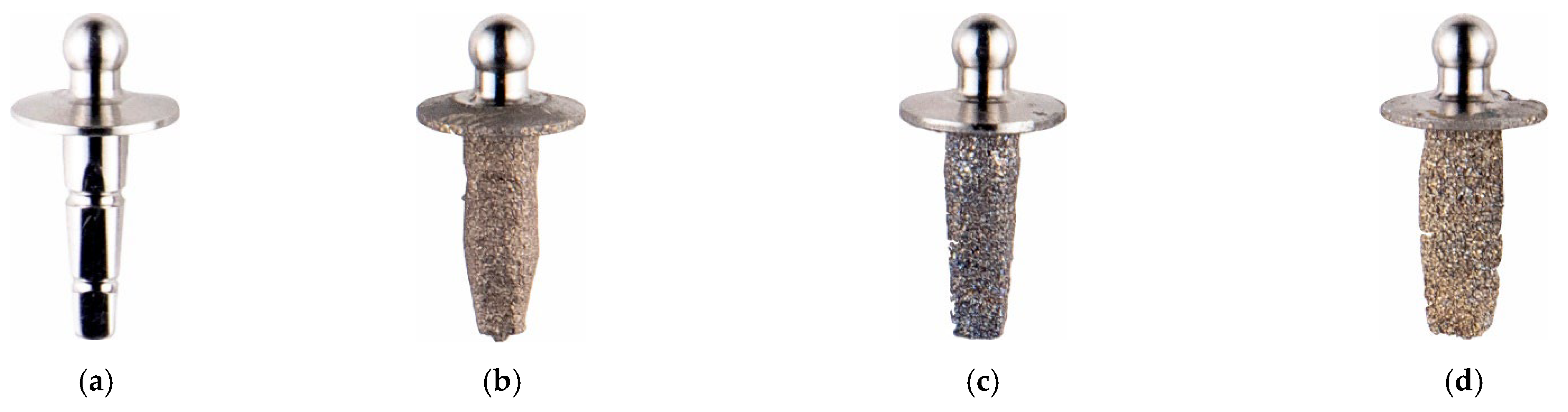
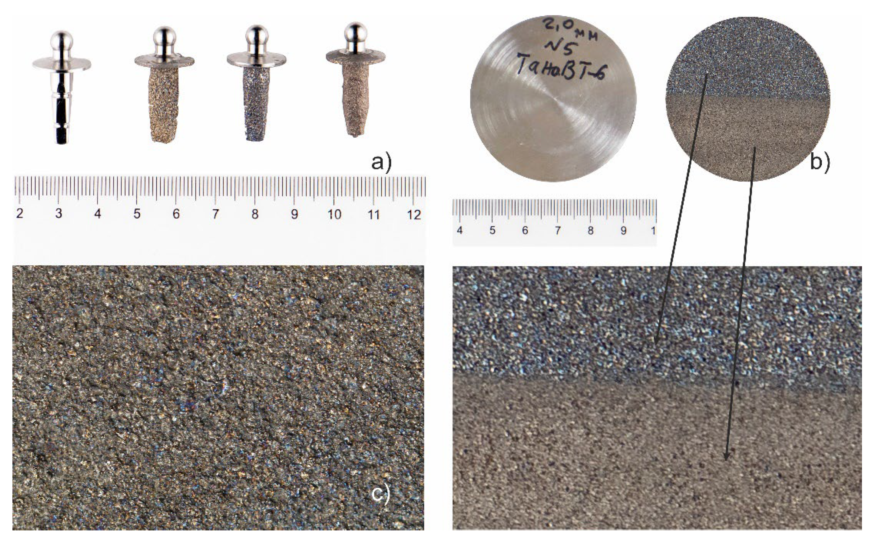
Grade 5 ELI alloy (Ti-6Al-4V ELI), equivalent to ASTM F136 [
2] was used as the substrate in this study for producing elbow joint implants, as well as reference discs of 2 mm and 50 mm diameter for further investigations.
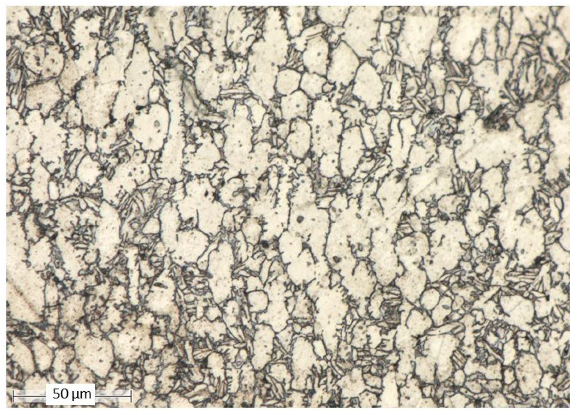
Table 1 presents the chemical composition of the Grade 5 ELI alloy. The microstructure of the alloy, shown in
Figure 1, is characterized by a coarse-grained structure typical of untreated rolled products.
Ta wire, type TVCH TU 95.353-75 (equivalent to ASTM F560), was used as the coating material for the microplasma spraying process.
Table 2 provides the chemical composition of this high-purity Ta wire, which meets ASTM F560 specifications for surgical implants. This Ta wire was employed to deposit the coating on the Grade 5 ELI substrate, continuously, using the microplasma spraying method.
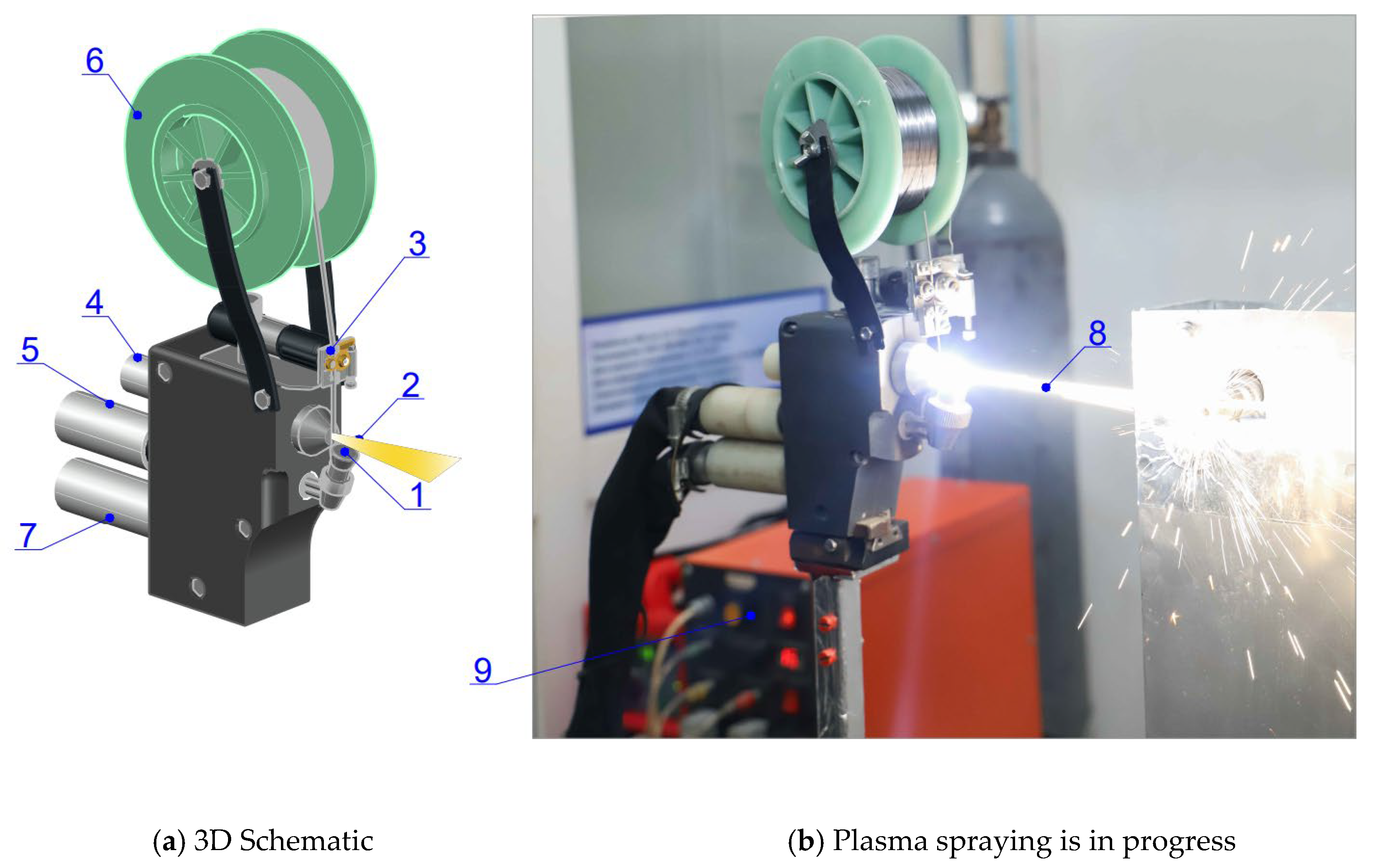
A microplasma coating method was employed in this study. The Ta wire used was developed through a collaboration between D. Serikbayev EKTU and the E. O. Paton Electric Welding Institute [
29]. Plasma spraying with wire spraying was conducted using a neutral Ta wire fed from a rotating coil.
Figure 2 shows the components of the microplasma spraying system, highlighting the compact torch mechanism that feeds the wire into the interelectrode section of the plasma jet [
30]. The plasma jet, responsible for heating, melting, and spraying the Ta wire, achieves temperatures of 5000 °C with an outflow velocity of 1000–3000 m/s [
31].
The system includes a feeder for adjusting wire feed speed by varying motor shaft revolutions and replacing the powder dispenser with a lightweight attachment. The plasma torch comprises a water-cooled cathode unit (cathode 2 and body 3) and an anode unit (1). A DC power source (9) ignites the plasma arc (8), stabilized by the nozzle channel walls and plasma-forming gas supplied through channel 1. Argon served as both the plasma-forming and shielding gas. The high temperature of the plasma jet melts the wire, which is then sprayed as droplets onto the rotating target. The temperature was measured during the process using a remote pyrometer. The reduced surface tension of the droplets, caused by melt overheating, facilitates detachment. The process stability, involving the microplasma spraying of a neutral wire through a 0.8 mm nozzle, depends on parameters such as plasma-forming gas flow rate, wire diameter, and power source settings [
32,
33].
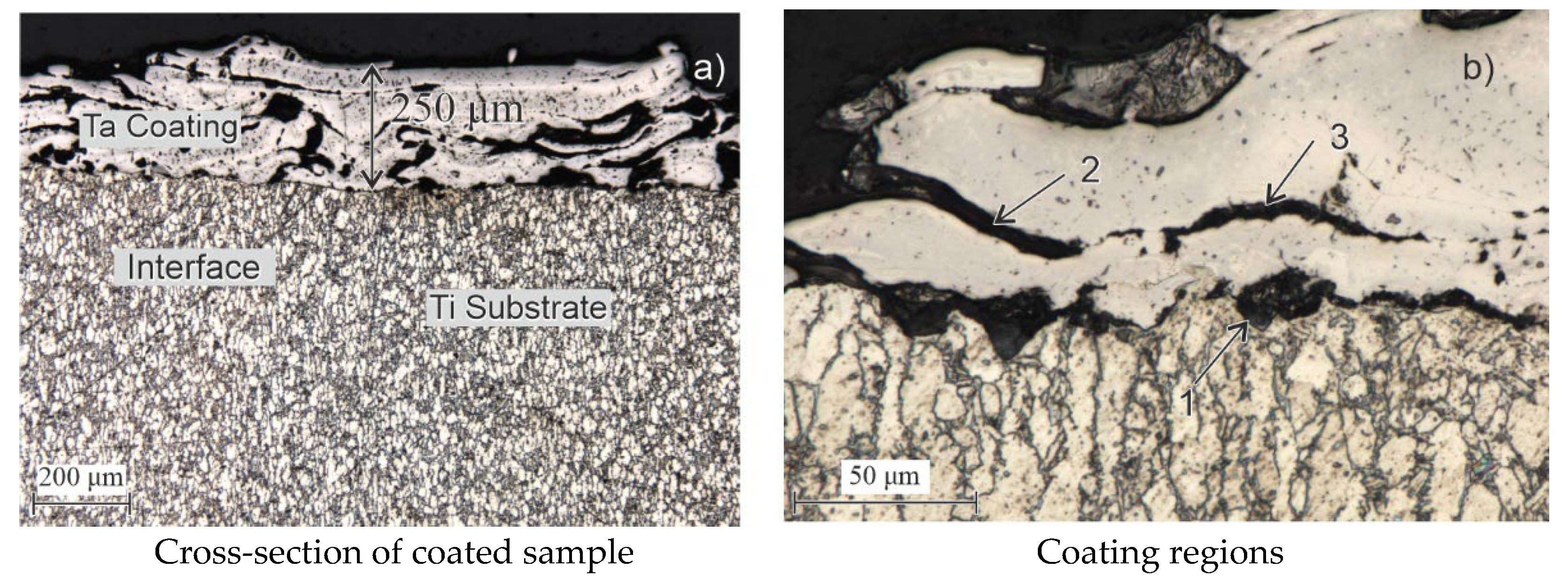
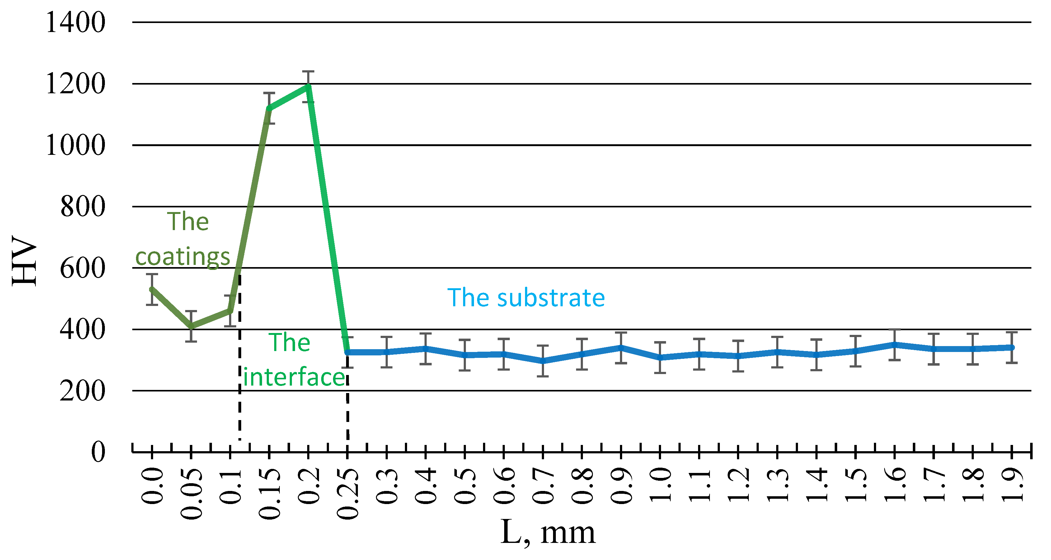
The microstructure of the coatings was examined, and their thickness was measured using a BX-51 metallographic microscope (OLYMPUS, Japan). The microstructural images were processed using the ATLAS.ti image processing software, version 24.1.1. and the Scientific DuraScan-20 (EMCO TEST, Kuchi, Austria) to analyze surface morphology. The images provide a qualitative assessment of differences in surface porosity features. Vickers hardness testing was performed using a load of 100 g on the indenter with an exposure time of 5 s at maximum load. Qualitative and quantitative phase analyses were conducted with an X’Pert PRO X-ray diffractometer (PANalytical). The XRD analysis of the coatings was conducted using a PANalytical X’Pert PRO diffractometer (Almelo, The Netherlands) with a CuKα radiation source (λ = 1.54060 Å). Phase identification was carried out using the ICDD database. The scan was performed over a 2θ range of 20.01° to 89.99°, with a step size of 0.02° and a dwell time of 0.5 s per step.
The microplasma was generated by the plasma torch (6), as shown in
Figure 3. The range and flux of sputtered material particles (2) depend on the diameter of the plasma-forming nozzle (3) and the pressure of compressed air (4). Plasma-forming gas (7) is generated between the cathode (5) and the power source (8), with the torch’s specific power characterized by its efficiency in converting electrical energy into the thermal energy of the plasma jet, which melts the sputtered wire (9). The spraying distance (L) was maintained to ensure uniform coating deposition and adhesion, while the opening angle (β) of the plasma jet influenced the dispersion and coverage of sprayed particles. The width of the spray spot (ρ
1) was controlled to achieve precise and consistent coating thickness.
Coating formation occurs as the wire’s end section melts and disperses. The Ta wire was fed through coils (11) by a drive mechanism (10 s). Plasma-arc deposition with Ta wire allows for the application of coatings (12) onto the Ti substrate (1). At higher plasma torch power, the process transitions to supersonic plasma outflow velocities, necessitating higher plasma gas flow rates. These conditions reduce the contact time of particles with the surrounding atmosphere, improving the quality of the coating [
34].
Continuous thermocyclic deposition of the surface layer on the implant creates favorable conditions for forming thick coatings. At high temperatures in the substrate contact area (12), the molten wire material is enriched (doped) by the plasma jet, improving the surface properties. The cyclic deposition process and the rotating substrate result in hardfacing. This repetitive effect forms a gas-saturated, porous layer with enhanced hardness. Coatings with reduced porosity exhibit increased density and hardness, attributed to forming a more cohesive, uniform, and structurally stable framework. This enhanced microstructural integrity improves mechanical strength and durability, making the coatings more resistant to deformation and wear. Researchers [
35] showed that to further improve the porosity and reduce abrasion, a biocompatible Ta alloy coating is applied to the Ti surface.
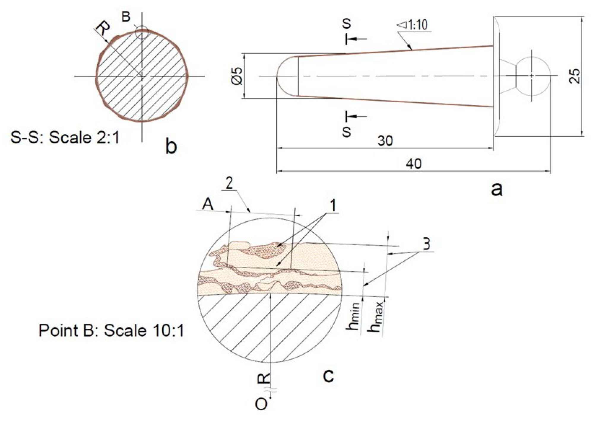
Figure 4 presents the elbow dimensions. Before coating, the surface area and volume are approximately 1090 mm
2 and 518 mm
3, respectively. After applying 100, 250, and 500-micron coatings, the surface area increases to 1110, 1139, and 1189 mm
2, while the volume rises to 584, 689, and 877 mm
3, respectively. Notably, the volume exhibits a more pronounced increase compared to the surface area, highlighting the cubic scaling effect of volume relative to the square-based growth of surface area. This confirms the expected geometric trend, where coating thickness contributes more significantly to volumetric expansion than to surface coverage. Moreover,
Figure 4 illustrates the mechanism of microplasma spraying on round surfaces. During thermocyclic microplasma spraying with Ta wire on an elbow implant, a multilayer coating is formed, continuously. The total thickness of the coating (3), ranging between h
min and h
max, results in wavy coatings (2) due to the superposition of individual spray tracks (1) relative to the sprayed surface with radius “R”. This occurs during the linear movement of the spray spot, where the uniformity of the coating is determined by the coating pitch “A”. Maintaining consistent pitch and layer thickness is essential to achieving a uniform, durable coating with optimal properties.
The maximum thickness of the sprayed layer (hmax) is influenced by the number of rotations of the substrate and the distance to the target. Achieving a coating with uniform thickness and minimal waviness requires careful optimization of the kinematic parameters of the spraying process, such as rotational speed, spray distance, and feed rate. These parameters directly affect the superposition of spray tracks and the overall quality of the coating.
Researchers [
27] derived Equation (1) to calculate the uniform thickness (
H) of the plasma-sprayed layer on a component. The equation considers parameters such as the spray spot radius (ρ
1), linear velocity of the plasma torch (υ
x), and spray pitch (
A) to model the thickness distribution:
where δ: coefficient characterizing the rate of increase in coating thickness at the center of the spray spot; p
1: spray spot radius (μm); υ
x: velocity of the plasma torch movement (m/min);
A: displacement step (m).
This equation accounts for the superposition of spray tracks during deposition, where A determines the spacing between successive layers. Optimizing A minimizes waviness, and controlling υx ensures consistent layer deposition. The coefficient δ, influenced by the plasma temperature and material melting point, reflects the deposition efficiency at the spray spot’s center.
The coating thickness at a specific point on the nozzle movement path can also be described by Equation (2), which calculates the coating height along the x-axis:
where H
(x): coating height at point x along the x-axis; h
max: maximum thickness of the sprayed coating (m);
x: coordinate of the plasma torch movement relative to the spray plane of the component.
This equation highlights localized thickness variations and is particularly useful for evaluating uniformity along a single axis. It provides a tool for predicting areas where thickness may deviate from the desired maximum (hmax) due to changes in spray spot overlap or torch velocity.
The uniformity and thickness of the coating also depend on the velocity of the plasma torch movement (vₓ) relative to the coated surface. For components with complex geometries, Equation (3) determines the spatial velocity of the plasma torch:
where
R: radius of the working area (surface with radius
R); (
): angular velocity (rad/sec); (
): velocity of movement along the z-axis (m/sec).
After deriving and rearranging the equation, the minimum coating thickness (hmin) can be calculated using the following formula:
where L is the length of the specimen (mm), I is the current (A), and ω is the speed of rotation (rpm). This formula matches the required value of h
min = 250 μm for the 5th experiment.
Equations (3) and (4) consider the rotational motion of the substrate and its vertical displacement. By optimizing υx, the deposition rate can be balanced to ensure consistent coverage over curved or irregular surfaces. Higher values of υx may reduce layer thickness but increase uniformity, whereas lower velocities may lead to thicker but less even coatings.
Equations (1)–(4) describe the spatial and local thickness distributions influenced by spray pitch (A) and spatial velocity (υ
x). These equations informed the selection of spray parameters to ensure uniform coatings with minimal waviness. The measured thicknesses in
Table 3, represented by h
min and h
max, align with these theoretical predictions, confirming the importance of optimizing spatial velocity and pitch to achieve consistent deposition.
The quality of plasma-sprayed coatings depends on controlling parameters such as arc current (I), voltage (U), gas flow rate (G), and wire feed rate (d). Kinematic factors like spraying distance (L), spraying angle (β), angular rotation speed (ω), and translational velocity (υx) also play a significant role. Thermophysical properties of the spraying process, such as atmospheric composition, cooling conditions, and coating formation dynamics, further influence the uniformity and quality of the resulting layer.
To determine the optimal regime for plasma spraying, it is essential to focus on the most significant factors while disregarding negligible variables and excluding constant parameters. The key factors influencing the maximum coating thickness (h
max) are grouped according to the technological stages. The relationship is expressed by the following equation [
36]:
where L: distance to the target, mm; I: current (A); ω: speed of rotation of the target (rpm); A: spraying pitch (mm/rev); d: diameter of the wire (mm); ρ: density of the wire (g/mm
3).
This equation reflects the relationship between the spraying distance (L) and current (I) versus the physical properties of the wire and rotational speed. Increasing L or I enhances hmax, but excessive values may compromise uniformity. Reducing ω (rotational speed) or A (spraying pitch) can improve coating thickness but may reduce processing efficiency. Fixing constants such as d and ρ allow precise control of variable parameters for optimal results.
Based on the derived equation and the discussed parameters, the effective factors influencing coating features were identified and selected, as shown in
Table 3. Key constants included A (spraying pitch, mm/rev), d (wire diameter, mm), and ρ (wire density, g/mm
3). Three variable factors: L (spray distance, mm), I (current, A), and ω (rotational speed, rpm), resulting in a total of nine planned experiments.
The experiments were grouped into three series to systematically analyze the effects of these variables and develop series I with optimal coating properties:
Series I: Tested ranges were L = 287–355 mm, I = 21–29 A, and ω = 8.2–7.4 rpm;
Series II: Tested ranges were L = 375–370 mm, I = 33–40 A, and ω = 7.2–6.7 rpm;
Series III: Tested ranges were L = 360–334 mm, I = 49–56 A, and ω = 6.0–5.2 rpm.
This structured approach provides a systematic framework for evaluating the influence of these variables on coating performance. It enables the development of a coating series with optimal properties, ensuring reliability and consistency in the application.
The experimental design was guided by Equation (4), which relates the minimum coating thickness (hmin) to the key parameters: spray distance (L), current (I), and rotational speed (ω). The ranges for these variables were selected to systematically evaluate their influence on the deposition process, i.e., the uniformity of the thickness and porosity, while the constants A, d, and ρ ensured consistency across experiments.
The results in
Table 3 validate the theoretical relationship described by Equation (4). The minimum coating thickness (h
min) initially increases with current (I), peaking at 35 A, before decreasing as I increase further. This behavior reflects the interplay of spray distance (L), rotational speed (ω), and current, where excessive current or suboptimal rotational speed can reduce coating uniformity and deposition efficiency.
Porosity and Thickness Measurement and Analysis
Porosity was measured using ImageJ image analysis software by segmenting the pore and solid regions within each sample. The corresponding cross-sectional images of the coating layers, including the substrate, are presented in
Figure 5, where pores and solid regions are visually distinguished by color segmentation. The pore area was quantified and expressed as a percentage of the total image area, as shown in
Table 3.
In the second series of experiments, the porosity values varied across different coating conditions. Experiment No. 4 (
Figure 5a) exhibited a porosity of 30.28%, while the lowest porosity was recorded in experiment No. 5 (
Figure 5b) at 24.99%. For the microplasma coating in experiment No. 6 (
Figure 5c), the porosity measured was 29.73%.
Among all nine experiments, experiment No. 5 demonstrated the lowest porosity value, indicating a higher coating density under the applied conditions.
Table 3 shows that exp. no. 5 provides the best microplasma spraying parameters, resulting in the smallest difference between the minimum (h
min = 250 μm) and maximum (h
max = 400 μm) coating thickness. This range ensures uniform, smooth, and almost defect-free coating layers, which are essential for practical applications. The other parameter sets result in larger differences in thickness, leading to uneven coatings that may compromise quality.
The initial microplasma-deposited layer, with a thickness of approximately 50 μm, is typically dense and characterized by excellent adhesion properties. However, to enhance the osteointegration process of bone tissue bonding with the implant—a minimum Ta coating thickness exceeding 250 μm is required [
14]. Increasing the coating thickness promotes porosity and is beneficial for biocompatibility but can pose a risk of delamination, reducing the implant’s longevity and reliability. Considering the high cost of Ta, the range of 250–400 μm was selected to balance cost, porosity, and mechanical reliability, ensuring even material distribution and optimal performance characteristics.
These findings highlight the importance of achieving a specific coating thickness range to optimize implant performance. Uniform coatings within the 250–400 μm range promote osteointegration, improve mechanical reliability [
13,
14], and ensure the cost-effectiveness of tantalum coatings, making Experiment No. 5′s parameters the most suitable for biomedical applications.


 ,
, 


