Article

The Elemental Migration Characteristics and Structural Damage Process of a ZnO Arrester Unit Surface Under a High-Frequency Voltage and Impulse Current

by
Jiyong Liu
1,2,
Jixing Sun
1,*,
Zhang Kun
1,
Yide Liu
1,
Fusheng Tian
1,
Baipeng Liu
1 and
Wang Chen
2
1
School of Electrical Engineering, Beijing Jiaotong University, Haidian District, Beijing 100044, China
2
State Energy Group Shuohuang Railway Company, Suning 062350, China
*
Author to whom correspondence should be addressed.
Coatings 2025, 15(4), 417; https://doi.org/10.3390/coatings15040417
Submission received: 19 February 2025 / Revised: 26 March 2025 / Accepted: 28 March 2025 / Published: 1 April 2025

Abstract

:
Arresters on electric multiple units (EMUs) usually experience premature aging under a high-frequency voltage and impulse current. In addition, they lead to overheating faults when subjected to the high-frequency overvoltage of electric railways. This research investigates the aging behavior of arresters when subjected to overvoltage and an impact current. An analysis was conducted on the impact of the aging duration at 1 mA and the frequency of overvoltage on a lightning arrester’s outer-layer components. The results show that the 1 mA DC reference voltage of the MOA sheet decreased, and the leakage current significantly increased at a 0.75 DC reference voltage through the aging of high-frequency voltage, and the duration of the applied voltage and the voltage bearing rate had similar effects on the two parameters. After aging, the Co and Bi elements on the surface of zinc oxide decreased and migrated to the depletion layer, resulting in a decrease in the dispersion characteristics of the zinc oxide agglomerate surface. Under the impulse voltage, the thermal stress on the surface of the zinc oxide increased, resulting in the damage to the zinc oxide grains, which aggravated the thermal stress concentration and reduced the performance of the zinc oxide. This study reveals the deterioration mechanism of high-frequency voltage- and impulse current gap-modulated MOA materials and provides a theoretical basis and data support for the development of and monitoring methods for new lightning arresters.

1. Introduction

The extensive high-speed rail network in China experiences frequent disruptions in train operations due to the occurrence of overvoltage, which is primarily attributed to the substantial traffic flow and extensive operational distances. Arresters are exclusively employed in EMUs to safeguard against overvoltage [1,2,3]. The aging of EMU arresters can lead to incidents such as thermal and burst accidents while driving [4,5]. Premature aging may occur on arresters as a result of various factors, such as the resonant overvoltage arising from the incongruity between the traction system and the train network within the railway infrastructure [6]. Harsh natural surroundings may affect arresters, as the umbrella’s external insulating layer may accumulate debris and dirt [7,8]. This phenomenon can result in unevenly distributed voltage and the ZnO resistor’s local overheating. Moreover, if the arrester comes into contact with rainwater or moisture, it may experience an increase in the leakage current, leading to a potential decrease in its operational lifespan [9,10]. The frequent resonance overvoltage between the vehicle and the grid can cause aging, which is the prominent cause [3,11,12] of arrester aging. Extensive research has been conducted within the field to tackle the problem of aging lightning arrestors. The primary factor contributing to the degradation of ZnO resistors is their limited capacity to effectively dissipate heat in elevated temperature conditions, resulting in a thermal breakdown [13,14,15,16]. A ZnO resistor’s degradation caused by the irregular distribution of sudden currents in specific areas leads to excessive thermal strain [17,18,19,20,21]. The electrical behavior of the nonlinear volt–ampere curve in the ZnO arrester can be elucidated by considering its tunneling mechanism within the framework of the Schottky barrier model. The phenomenon takes place when electrons, subjected to immense stress, traverse obstacles originating from the energy level at the interface of the surface. Currents flowing through the arrester rapidly change as the applied voltage increases, resulting in obvious and deteriorated nonlinear characteristics [22,23,24]. To further understand the aging mechanism of the arrester, various models have been proposed for the simulation and analysis of ZnO arresters’ dynamic characteristics under different lightning strike conditions. S. Tominaga and K. Azumi proposed a nonlinear inductance model [25], which expresses the arrester condition in a narrower wavefront time range of 1 to 8 μs but requires more data points to ensure accuracy. The IEEE working group then presented their model, which set the volt–ampere characteristics, the ZnO resistor’s number, and thickness. This arrestor model is applicable within 0.5–45 μs of front time. Lowering the front time increases the residual voltage of the arrestor. Based on the IEEE model, Pinceti [26] proposed the PINCETI model. Later, Valdemir S. Brito [27] proposed a resistive leakage current model that can accurately describe the distribution under a wide frequency domain and large amplitude conditions. The simulation of the model in waveforms such as 3/6 μs, 4/10 μs, and 8/20 μs coincided with the test results. There was a significant error under the 1.5/26 μs waveform simulation. The authors of [28,29,30,31] proposed a plate brick model to calculate the performance of a ZnO resistor. This model is suitable for the macroscopic study of the resistive chip grain boundary capacitance, etc., and the calculation of the overall characteristics [32,33]. However, there is a gap between the homogenization and the actual microstructure. The current arrestor model requires many human-set curvilinear morphological control parameters, and tests are still needed to verify the simulation reliability [34,35].
This work investigates the issue of an insufficient number of arrestors under frequent overvoltage conditions. A testing platform was constructed to examine the effects of the aging duration and overvoltage frequency on a leakage current’s features in arrestors, using a DC reference voltage of 1 mA (U1mA) and a reference leakage current with a 0.75 DC reference voltage (I0.75U). In addition, this study presents the outcomes of the ZnO resistor components’ migration process in arrestors pre- and post-aging. Moreover, it examines two different overvoltages’ impact on the arrestor’s aging process. This study provides support for the theoretical and empirical advancement of arrestors with enhanced capacity and dependability, specifically designed for implementation in electrified railway networks.

2. A Lightning Arrester’s Temperature-Rise Analysis in a Mobile Train Situation

2.1. Frequent Overvoltages Occur When the Lightning Arrester of a Train in Motion Is in Operation

The power supply interval in the EMU generates the converter device’s switching frequency when it operates. The proximity of the frequency to the line’s oscillation frequency leads to an overvoltage phenomenon characterized by resonance with high-order harmonics. The arrester experiences a thermal impact due to the presence of a high-voltage amplitude distribution range with a wide frequency and prolonged duration.

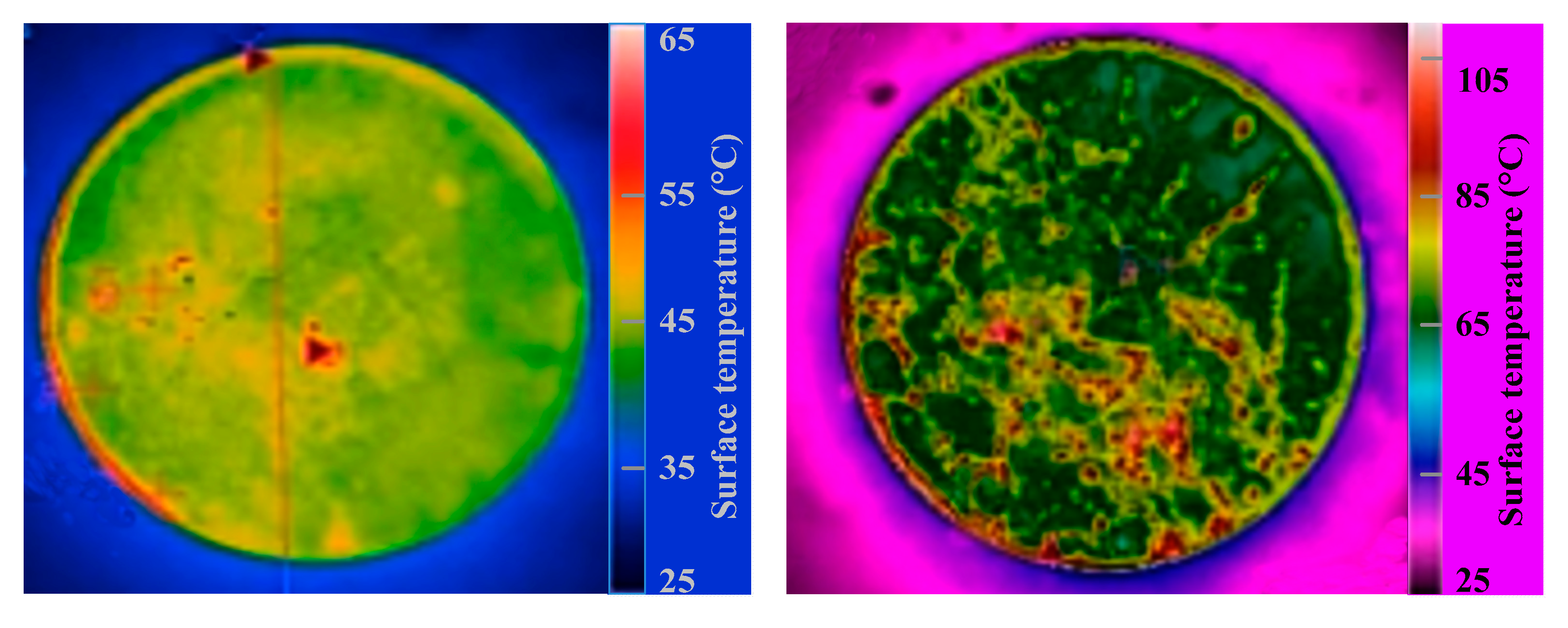
2.2. Analysis of the Thermal Process in Lightning Arresters

During instances of overvoltage, the surge arrester will rise in temperature. This process consists of both transient and steady-state thermal characteristics, such as a transient temperature rise and a heat dissipation process to reach thermal equilibrium. The internal resistor of the arrester generates Joule heat, due to the high harmonic overvoltage flowing through the resistive harmonic current, causing a transient temperature rise in the zinc oxide resistor and aluminum-gasket core column. Despite the heat dissipation process, the sealed arrester may suffer thermal collapse if the heat absorption power exceeds the heat dissipation power. Therefore, the arrester needs to have good heat dissipation performance to maintain thermal stability. The primary mechanism behind the temperature increase in the arrester, when subjected to overvoltage, is mainly the resistance part’s transient heat absorption. This is because the duration of the overvoltage is generally short, and the arrester resistance’s transient increase in temperature is calculated based on the adiabatic process. The resistor’s transient heat Q is calculated within the ZnO arrester.
Q = 0 t 0 u ( t ) i ( t ) d t
In Equation (1), t0 represents the period during which the arrester experiences overvoltage, and u(t) and i(t) denote the instantaneous voltage values across the ZnO resistor’s terminals and the current flowing through it at that moment, respectively.
Due to the significantly higher resistivity of the arrester core body compared to the metal gasket, it is possible to disregard any temperature increase in the metal gasket. The transient energy absorbed by the arrester is solely considered, which contributes to the generation of heat in the resistor. Equation (2) can be used to calculate the increase in temperature in terms of a ZnO resistor-equipped lightning arrester.
Q = C M O R i = 1 n m i Δ T ,
where CMOR represents the resistor’s specific heat; mi represents the resistor’s mass on the body of the arrester core; and ΔT denotes the resistor’s temperature rise. ΔT, the rising temporary temperature, is determined by the following:
Δ T = Q C M O R i = 1 n m i
Under the impulse current, the heat dissipation of the arrester is not effective, and there will be local thermal stress inside, which will affect the life of the arrester. In addition, the potential for an explosion may arise due to the thermal expansion resulting from the elevated temperature. Equation (3) can be used to investigate the aging of resistors for lightning arresters on the train.

3. Experiment

3.1. Equipment for Testing the Aging of Resistors Used in Lightning Protection Systems

The equipment for conducting an aging test of resistors comprises an AC power supply with programmable features, a transformer, a voltage divider consisting of resistive components, and the test specimen, etc. The primary device utilized for measuring the electrical parameters is the tester, designed to analyze the voltammetry characteristics of lightning arresters. Figure 1 shows the test’s main circuit diagram. A power supply with a high frequency and voltage was utilized to deliver diverse frequencies and amplitudes of alternating current (AC) voltage, imitating different harmonic overvoltages produced during the operation of rolling stock. It comprises an IT7624 AC programmable power supply and a transformer that increases the voltage. The power supply with programmable capabilities can generate an AC voltage of up to 300 V, operating at a maximum frequency of 5 kHz and delivering a power output of 54 kVA. Additionally, it possesses the capability to accurately replicate various waveforms and harmonic outputs. The purpose of employing a step-up transformer was to further increase the high-voltage amplitude to fulfill the demands of high-voltage testing. The test ratio was set at 1/500, and the rated output voltage was specified as 100 kV. A voltage of around 3 kV was applied to the resistor at both terminals, and a capacitive divider voltage sensor was utilized to safeguard the measuring apparatus. The ratio of the capacitive divider test was 1.5 k/1.

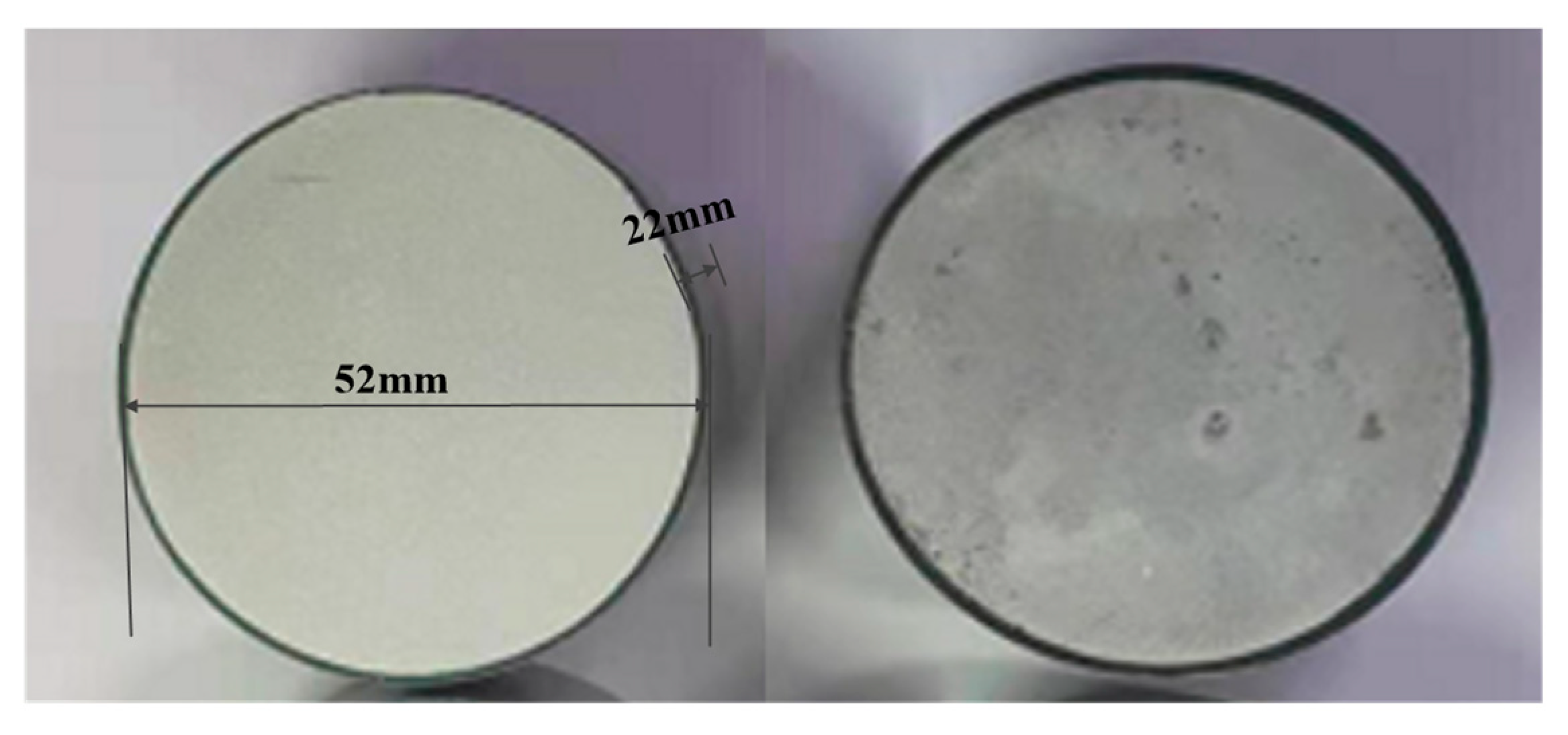
3.2. Arrester Resistor Test Product

Two variants of ZnO resistors were chosen for evaluation to enhance the precision of the examination (Figure 2). Aged and unaged discs were chosen for the circular discs’ experimental comparison. Table 1 lists the unaged resistors’ basic parameters.
The electrical characteristics of numerous valves utilized in the experiment exhibited similar parameters, and the aged and unaged resistors adhered to identical specifications. However, there were variations in the relevant electrical parameters. In addition, the experiment aimed to identify resistors that possessed similar initial parameters.

3.3. Aging Test Program

The resistive leakage current values of a resistor sample were measured through an aging test conducted under high harmonic voltage. The measurements were taken before and after the test using U1mA and I0.75U. As the arrester resistor’s heating temperature primarily relies on the magnitude of resistive leakage current, evaluating its aging condition indirectly was achieved by examining the variation in I0.75U. The resistor samples underwent various conditions during testing to investigate the aging mechanism of the resistor by analyzing the alterations in the relevant electrical parameters. The aging conditions of the arrester resistor plate included the withstand voltage time, voltage frequency, and charge rate.
After aging, a DC power supply was utilized to establish a voltage range from 1 kV to 6 kV when conducting measurements on the resistor’s electrical parameters. The step voltage was configured at 5 V, and a threshold current was maintained at 2 mA to enhance the testing efficiency and accuracy. Table 2 lists the DC power supply’s fundamental electrical parameters.

4. Effects of High-Frequency Voltage on the Aging Characteristics of Surge Arresters

The withstand voltage duration, frequency of voltage, and rate of charge affect the level of aging in a lightning arrester. This study involved a comparison of the U1mA and I0.75U of the resistor after completing the aging test.

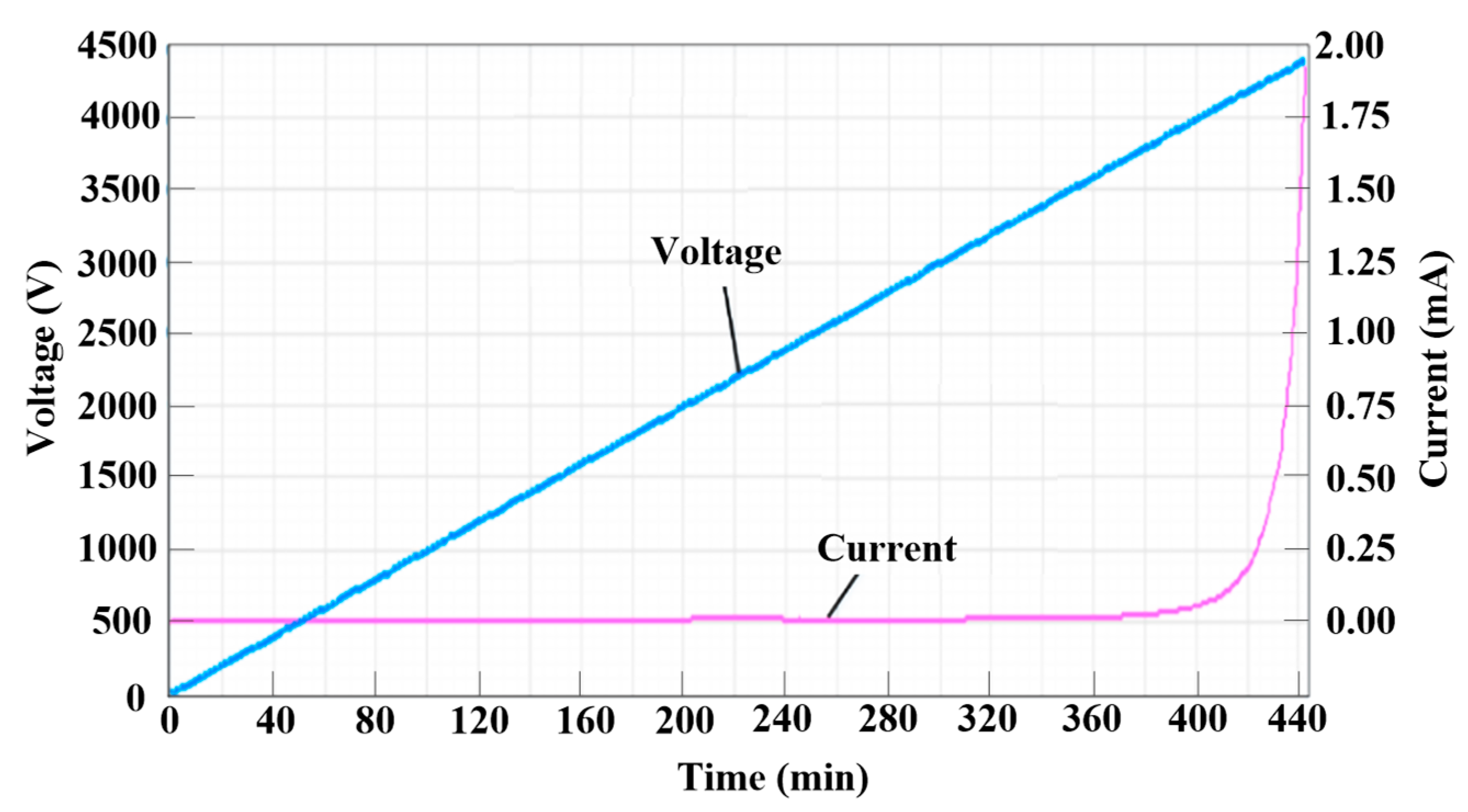
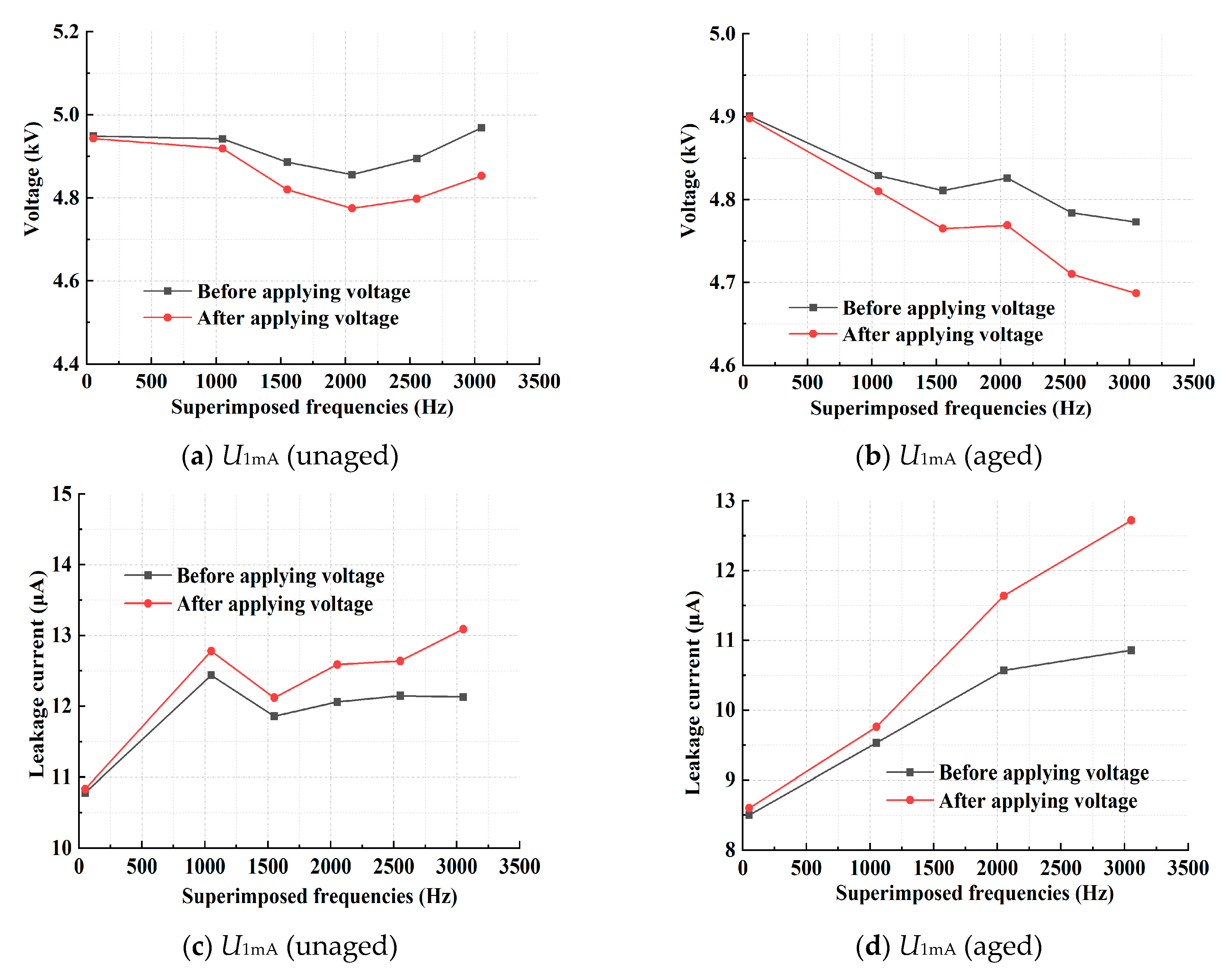
4.1. Effect of the Withstand Voltage Duration on the Resistor Plate

For comparison, we subjected the resistor to a frequency voltage of 3 kV for varying periods. In addition, the voltage was applied during withstand voltage periods lasting 3 h, 4 h, 5 h, and 10 h. Figure 3 shows the curve depicting the relationship between the voltage and the current for the resistor before the voltage was employed.
After the test, a typical arrester resistor voltammetry characteristic curve (10 h) was obtained, as shown in Figure 4.
The ZnO resistor’s volt–ampere characteristic curve after aging exhibited a comparatively lower profile compared to the unaged resistor, with a slight rightward shift. The aged resistor’s nonlinear coefficient was reduced compared to the unaged resistor. In addition, the aged resistor exhibited a higher leakage current in the low-current region of its volt–ampere characteristic curve, when compared to the unaged one at the same voltage.
The volt–ampere characteristic was measured during each withstand voltage to record the electrical parameters. The U1mA of the resistor experienced a decrease, while the I0.75U exhibited an increase, under different withstand voltage times with a working frequency of 50 Hz (Figure 5).
After undergoing a maximum withstand voltage period of 10 h, the unaged resistor exhibited a U1mA value of 5.027 kV and demonstrated an 11.55 μA I0.75U. After being subjected to prolonged withstand voltage, the U1mA decreased to 5.01 kV, while the I0.75U exhibited an increase to 12.17 μA. The aged resistor’s initial U1mA was measured at 4.762 kV, accompanied by an I0.75U of 7.88 μA. It dropped to 4.70 kV, accompanied by an I0.75U of 8.76 μA after prolonged withstand voltage. A minor decline was observed in the DC reference voltage, while a slight rise was noted in the resistive leakage current following extended withstand voltage.

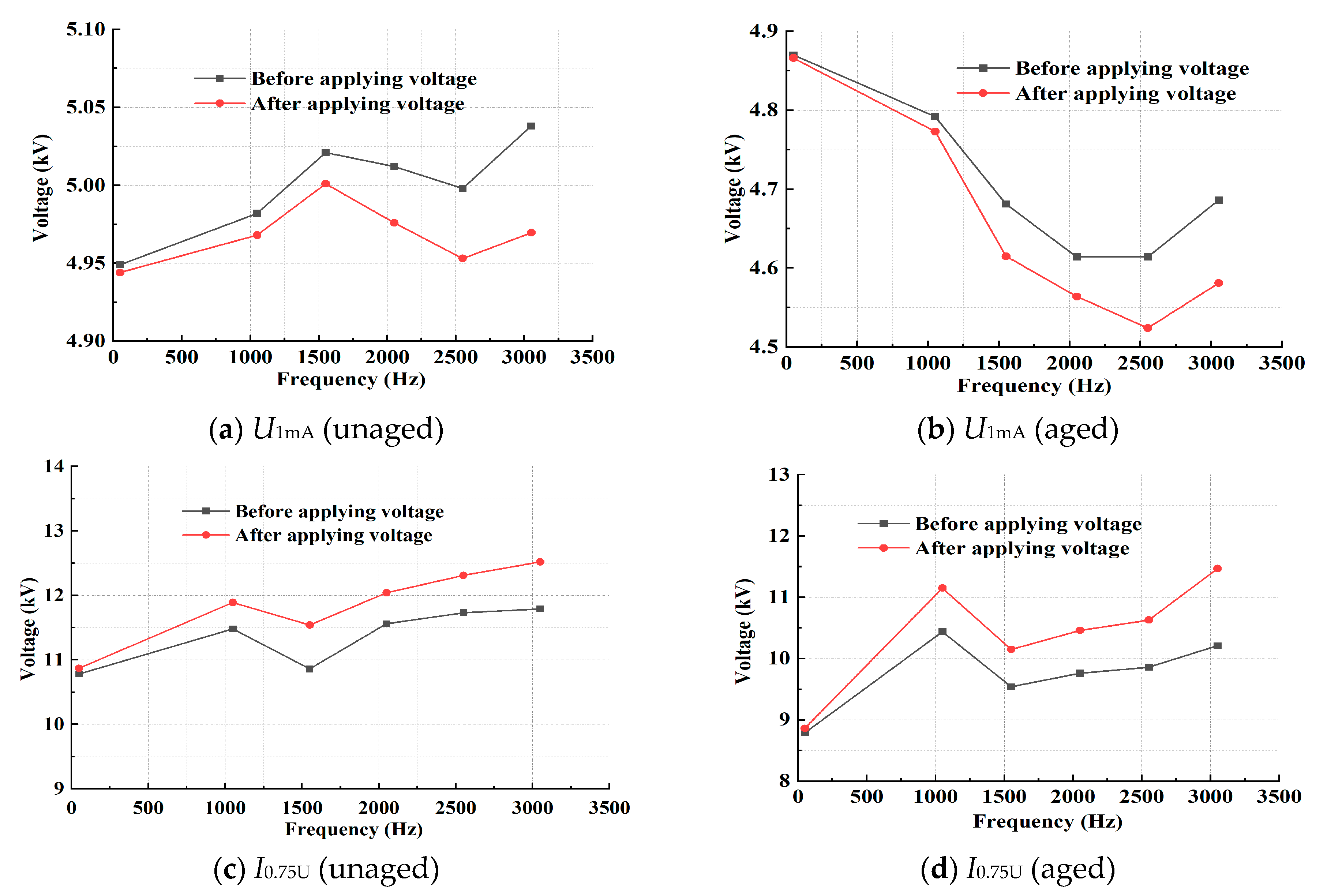
4.2. Impact of Varying the Withstand Voltage Frequencies on Resistor Aging

A withstand voltage with 3 kV and different frequencies was applied to the resistor over 5 h to examine the impact of elevated harmonics on the resistor’s electrical characteristics. The frequencies used were 21, 31, 41, 51, and 61 times the working frequency. The volt–ampere characteristic was measured during the withstand voltage process to record the electrical parameters. In addition, variations in the resistor’s electrical parameters were measured at different frequencies of the withstand voltage (Figure 6).
The resistor’s U1mA decreased, while the leakage current increased, when subjected to prolonged exposure to an elevated harmonic voltage (Figure 6). Particularly, the U1mA for the unaged resistor was recorded as 4.998 kV, which decreased to 4.953 kV after applying the voltage for five hours under a voltage of 3 kV at the 51st harmonic. Additionally, the I0.75U was 11.73 μA and increased slightly to approximately 12.31 μA. Similarly, the U1mA of the aged resistors that underwent voltage application under identical conditions was 4.61 kV before aging and 4.52 kV after aging. In addition, the I0.75U was 9.86 and 10.63 μA, respectively. The results suggest that the resistor’s electrical parameters are more significantly influenced by high harmonics.

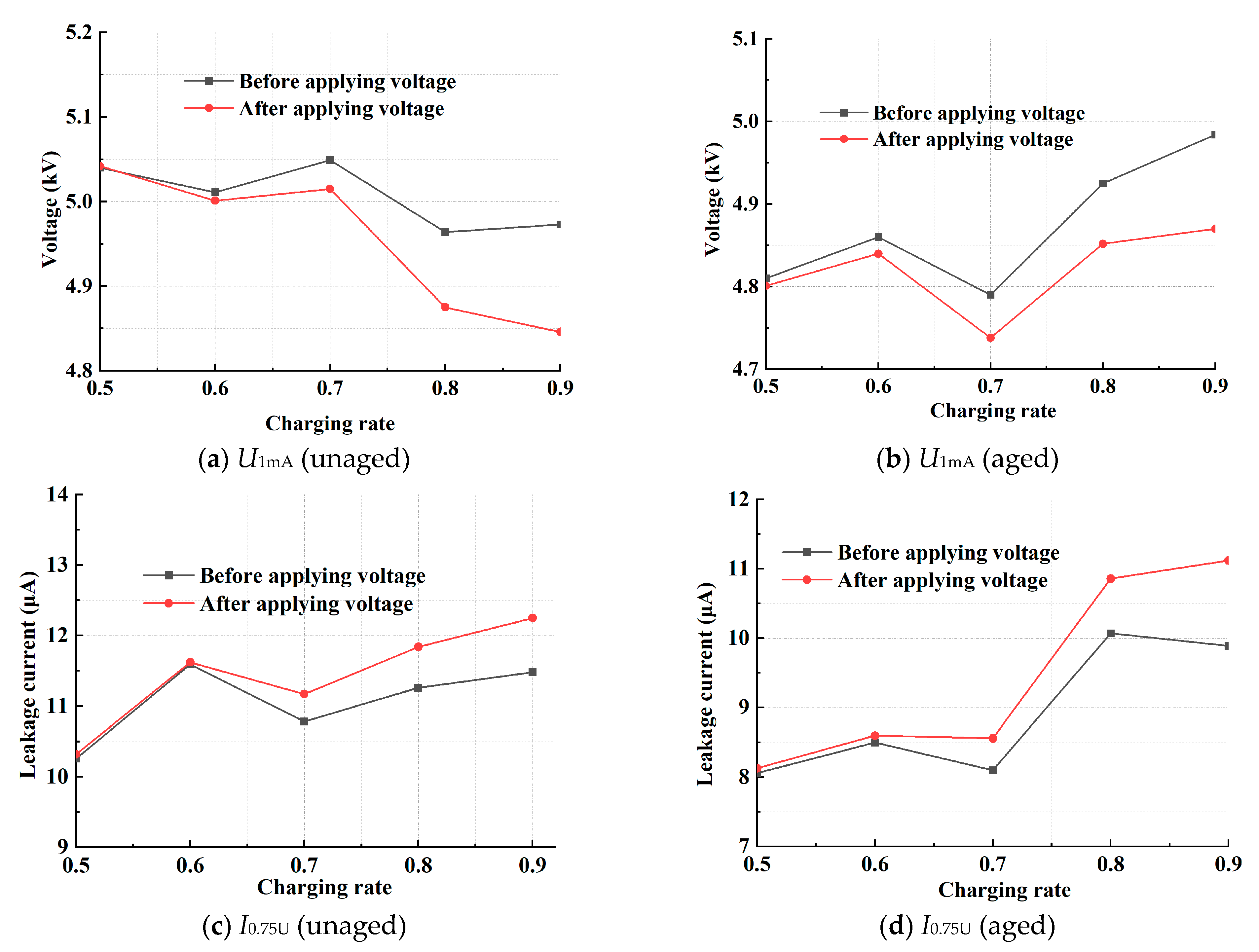
4.3. The Impact of the Charging Speed on the Deterioration of Resistors

Voltammetry is a category of electroanalytical methods used in analytical chemistry. To investigate the impact of varying charge rates on the resistor’s electrical parameters, experiments were conducted with a constant frequency of 50 Hz and a withstand voltage time of 5 h. The voltage charge rate was adjusted to 0.5, 0.6, 0.7, 0.8, and 0.9 for analysis. The resistor’s electrical parameters were measured using voltammetry tests to analyze the variations in the electrical characteristics at different rates of voltage charging, following each withstand voltage (Figure 7).
The results showed that at a charge rate of 0.8, the voltage amplitude was approximately 4.0 kV, and the U1mA values of the unaged resistor before and after the withstand voltage were 4.96 kV and 4.875 kV, with I0.75U values of 11.26 μA and 11.84 μA, respectively. The corresponding U1mA for the aged resistor was 4.92 kV and 4.852 kV, with I0.75U values of 10.07 μA and 10.86 μA, respectively. With a charge rate of 0.9, the voltage amplitude was approximately 4.5 kV, the U1mA values of the unaged resistor before and after withstand voltage were 4.973 kV and 4.846 kV, respectively, and the I0.75U values were 11.48 μA and 12.25 μA, respectively. For the aged resistor, the U1mA values were 4.984 kV and 4.871 kV, and the I0.75U values were 11.26 μA and 11.84 μA, respectively. Under smaller withstand voltage conditions, such as 0.5 and 0.6, there was no significant change in the parameters of the resistor; however, when the higher charge rate was applied for a longer period, the U1mA of the resistor experienced a decrease, while I0.75U underwent a significant increase, which caused the resistor’s active power to increase and led to a significant increase in the temperature of the resistor at the end of the aging test.

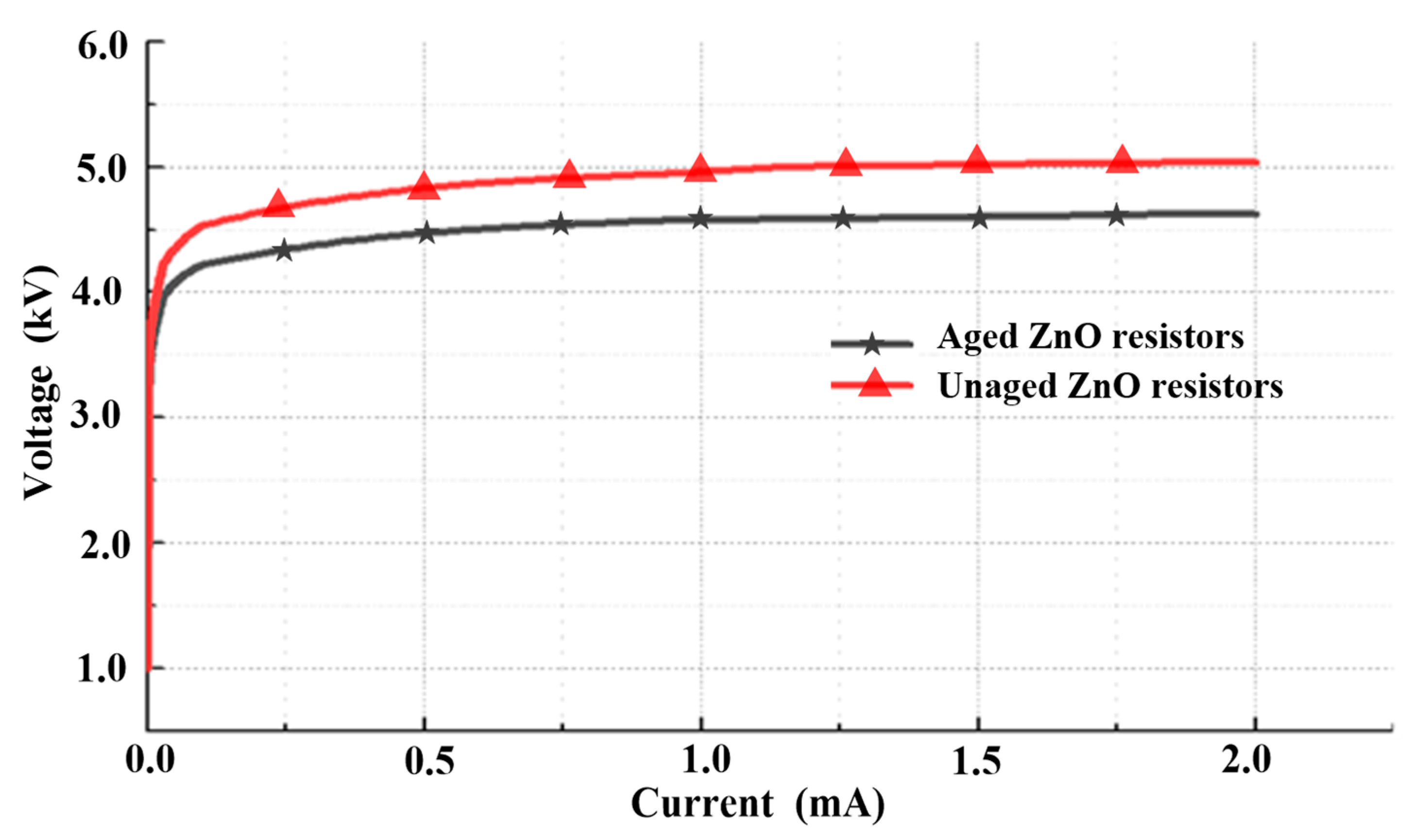
4.4. Effect of the Withstand Voltage Frequency on the Aging of the Resistor

The same group of resistors was subjected to a 3 kV frequency voltage for 5 h to examine the elevated superimposed harmonics’ impact on the resistor’s electrical parameters. In addition, the superimposed frequencies underwent alterations of 21st, 31st, 41st, 51st, and 61st. The volt–ampere characteristics were measured following each voltage application to record the electrical parameters. Revisions were made to the resistor’s electrical parameters when subjected to varying frequencies of voltage application (Figure 8).
The resistor U1mA experienced a decrease, while the I0.75U increased, after applying high superimposed harmonics for a long time (Figure 8). In the aging test with the 61st harmonic superimposed on the working frequency, the U1mA of the unaged resistor was 4.952 kV before the test and 4.891 kV after the test, and the I0.75U was 12.15 μA before the test and 13.14 μA after the test. Under the same test conditions, the U1mA of the aged resistor was 4.774 kV and 4.692 kV before and after the test, respectively. The I0.75U was 10.91 μA and 11.91 μA, respectively.
The aging effect of the same kind of resistor varied when changing the withstand voltage time, voltage frequency, charge rate, and superposition frequencies, and the relevant electrical parameters of some aging resistors varied more under the same working conditions, with the increase in the withstand voltage time, voltage frequency, charge rate, and superposition frequency.

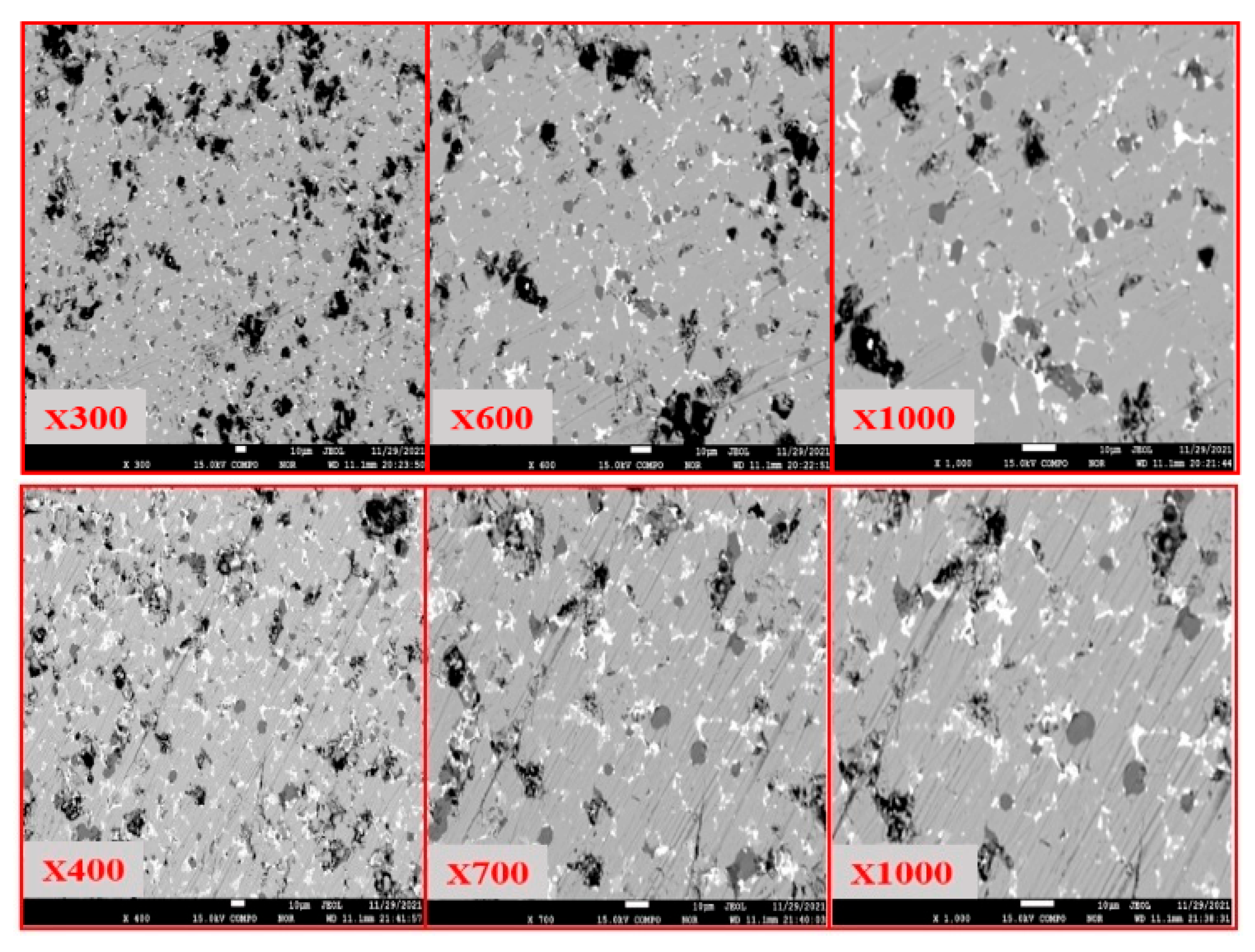
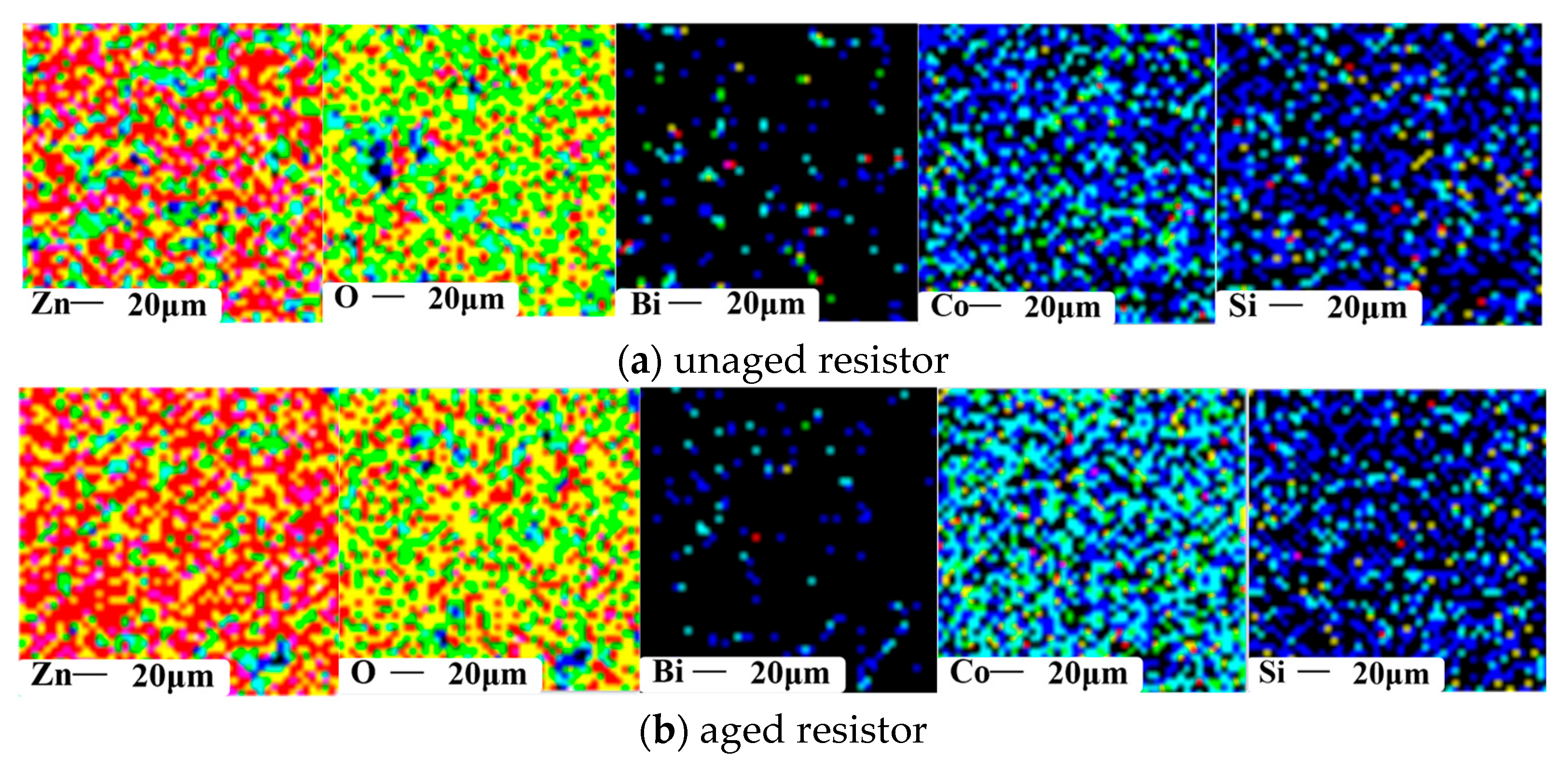
5. Apparent Morphology and Element Migration Characteristics of the Surge Arrester

During the sintering process at high temperatures, the ZnO resistor will form a symmetrical double-Schottky barrier layer. The linear performance is determined by the barrier height, and the microstructure is arranged in the form of boundary–grains. Under long-term high-frequency overvoltage, the resistive leakage current of resistors increases, and the electric charge on their microstructures migrates due to thermal motion, resulting in asymmetrical barrier layers on both sides of the grain boundaries that reduce in height. Aging tests on the resistors suggest that their leakage current and DC reference voltage change most significantly when subjected to different working conditions due to increased chargeability. Furthermore, a single harmonic frequency has a stronger impact on the aging of resistors than superimposed harmonics. Additionally, the prolonged application of an increasing voltage at a power frequency exhibits little impact on the electrical parameters of either aged or non-aged resistors. The surface of the non-aged resistor is smooth and flat, and the side insulating paint is glossy, without obvious abnormality. The aluminum electrode layer of an aging resistor will have traces of suspected chemical corrosion, the insulating paint on the side will be matte and rough, and the color will be uneven. Before scanning, we kept the surface of the resistor clean, complete, and free of dirt and oil stains. The results of the electronic scanning showed that the surface morphology of the ZnO resistor in different states was not significantly different under 1000× magnification, as shown in Figure 9.
To analyze the resistor’s internal structure, we selected resistors with obvious signs of aging on the surface for crushing and analyzed the changes in the distribution of the chemical elements; the results are shown in Figure 10.
The composition elements of different aged resistors were similar, including many metal elements, but the composition content was different. In the aged resistor, the proportion of Zn was less than that of the non-aged resistor, but there was more O, Bi, and Co, and the other metal elements had no obvious change. After aging for a long time, water vapor is more likely to invade, which is the reason for the significant increase in the oxygen elements in the resistor. The surface of the non-aging resistor is mainly composed of Zn, and there are no elements such as Bi and Co, but flashover occurs along the surface after aging. During the aging process, the resistor absorbs energy and generates heat. The thermal activation generated inside can promote the migration of cations such as Bi and Co to the depleted layer, resulting in the appearance of Bi and Co on the aluminum electrode’s outermost layer. Due to the damaged internal resistor insulation and external overvoltage, the probability of lightning arrester failure increases.

6. Discussion on the Aging Characteristics of the Arrester

The thermal process of an arrester under overvoltage conditions was analyzed. To maintain a balance between the heat generated and dissipated by the arrester, it is important to select a zinc oxide resistor with high heat capacity and a low temperature coefficient and to improve the heat dissipation capacity of the external insulation sheath as much as possible, to ensure that the temperature of the resistor does not exceed the threshold. Furthermore, when the arrester is in operation, it will experience multiple impulse voltages after passing through the power supply section, as shown in Figure 11.
This can lead to the deterioration of the resistor, as seen in the laboratory test conducted at 25 °C with 12 shocks per 1 min. The temperature of the unaged resistor was close to 37.7 °C, while the temperature of the unaged resistor was close to 42 °C after 72 h of high-frequency testing, as shown in Figure 12. Under the impulse current, there is a concentration of thermal stress on the surface of the arrester, which will lead to grain breakage.
The micromorphology of the arrester was observed, and it was found that the arrester grains were damaged after multiple shocks, which would occur under the impact current, as shown in Figure 13.

7. Conclusions

This research investigated the degradation of an arrester subjected to frequent occurrences of overvoltage. The arrester’s I0.75U characteristics were investigated, as well as U1mA, by considering the influence of the aging duration and the overvoltage frequency. This study investigated the valve components’ migration process in arresters pre- and post-aging. In addition, it examined the impact of two types of overvoltage on the aging mechanism of the arrester. A theoretical foundation and empirical evidence were provided to support the advancement of arresters with enhanced capacity and reliability in electrified railways. The conclusions can be summarized as follows:
(1)
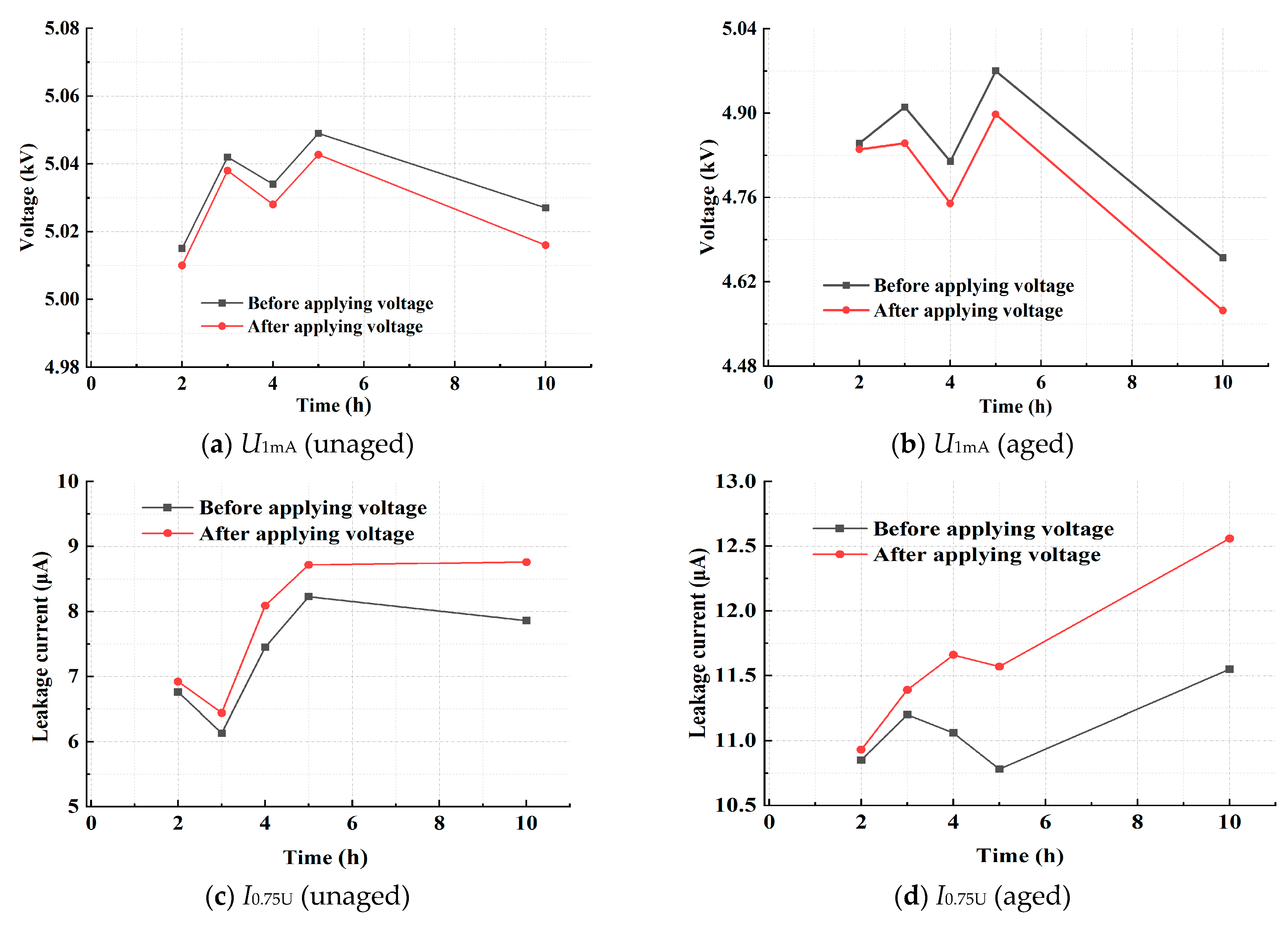
The aging duration with the ZnO resistor’s charge rate increases with increased applied voltage frequencies. After the process of aging, there is a noticeable decline in the 1 mA DC reference voltage, accompanied by an upward trend in the leakage current under this voltage. Nevertheless, the rise observed in this regard is significantly less compared to that in the frequency of the applied voltage.
(2)
When subjected to high-frequency voltage conditions, the resistor element migrates. During the aging process, the resistors absorb energy and heat up. The internal heat activation can push the Bi, Co, and other cations to the depletion layer and cause the Bi and Co elements to appear on the aluminum electrode’s outermost layer. Meanwhile, water vapor is more likely to invade, resulting in a significant increase in oxygen elements in the resistors.
(3)
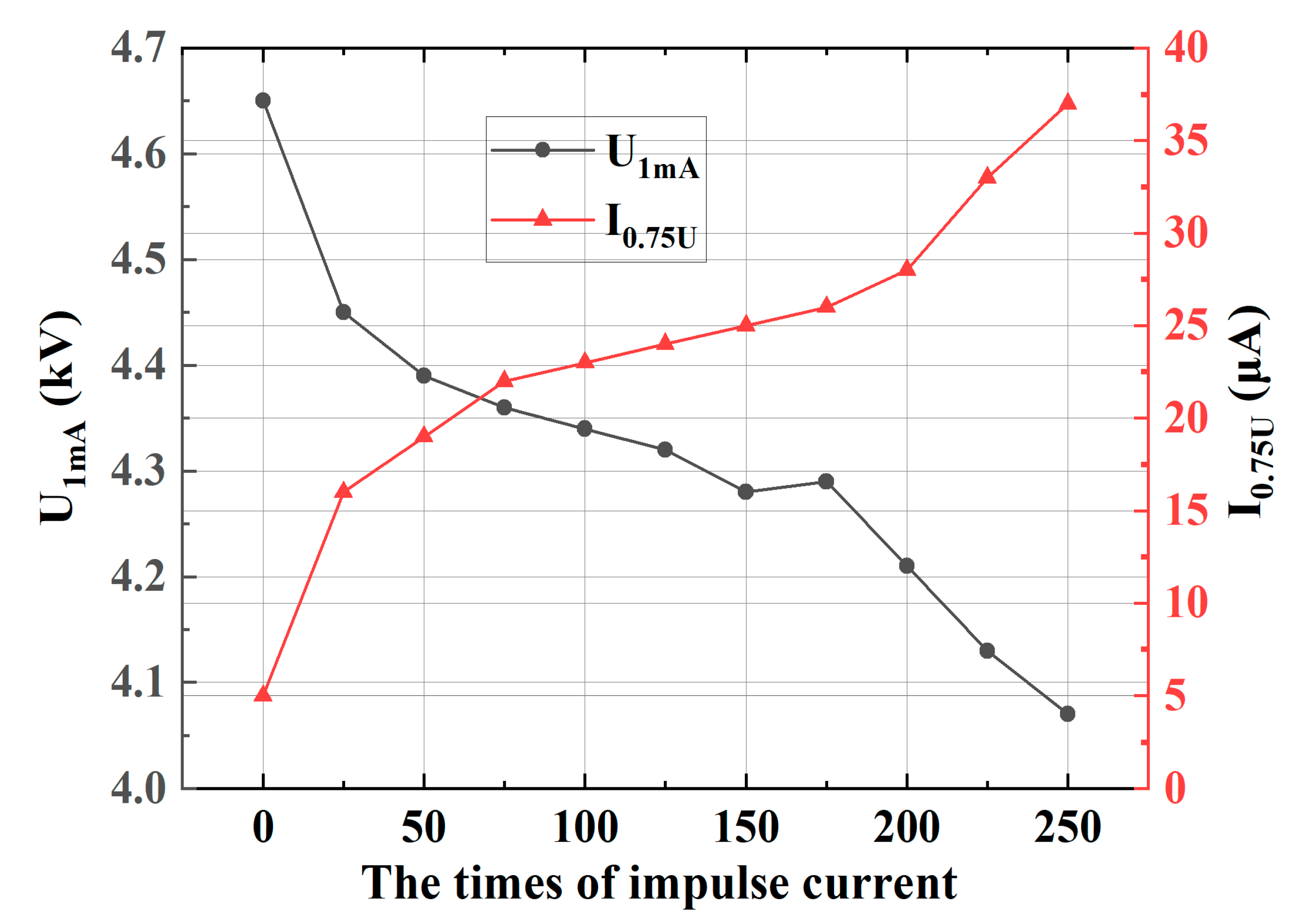
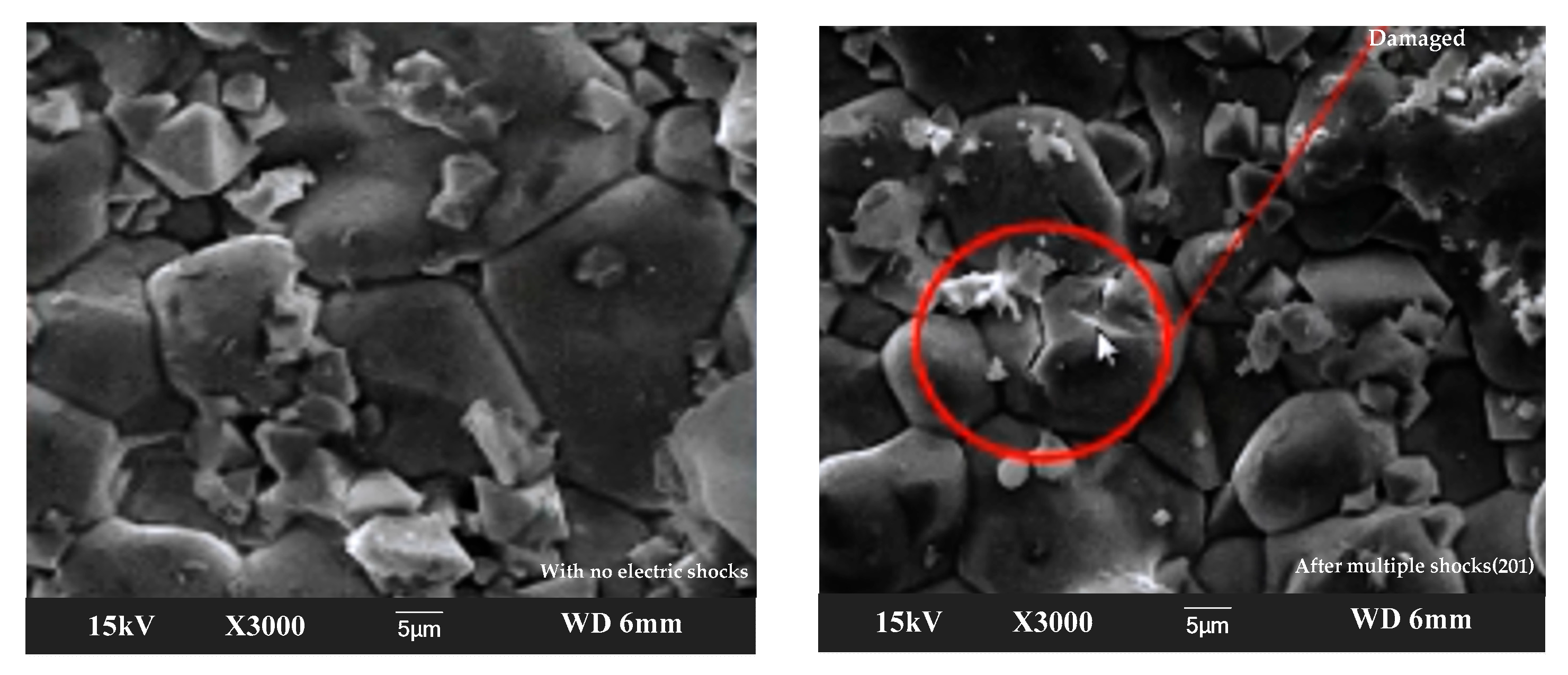
When subjected to various impacts, the arrester resistor experiences a decrease in its 1 mA DC reference voltage, which is approximately 0.75 times the leakage current under the same reference voltage. This leads to an increase in the valve temperature and uneven heat distribution, which ultimately causes grain rupture and compromises the functionality of the resistor.

Author Contributions

Methodology, J.S., Z.K. and Y.L.; Software, F.T.; Validation, J.L. and B.L.; Formal analysis, J.S. and Y.L.; Investigation, Z.K.; Writing—original draft, F.T. and B.L.; Writing—review & editing, J.L.; Supervision, W.C.; Project administration, W.C. All authors have read and agreed to the published version of the manuscript.

Funding

This work was supported by the Fundamental Research Funds for the Central Universities (2024JBMC039), the National Natural Science Foundation of China (52377131), and the Science and Technology Project of the National Energy Group (SHTL-21-08, SHSN-22-05, SHTL-2022-9, SNFZ23086).

Institutional Review Board Statement

Not applicable.

Informed Consent Statement

Not applicable.

Data Availability Statement

Data is contained within the article.

Acknowledgments

The authors would like to thank the reviewers for their pertinent comments that helped to improve the quality of this paper.

Conflicts of Interest

Author Wang Chen was employed by State Energy Group Shuohuang Railway Company. The remaining authors declare that the research was conducted in the absence of any commercial or financial relationships that could be construed as a potential conflict of interest.

References

  1. Tian, F.; Li, X.; Chen, J.; Cao, J.; Zhang, S. Research on the Structural Optimization and Electrical Characteristics of the Ar-rester in Electric Multiple Units. IEEE Trans. Instrum. Meas. 2025, 74, 3514411. [Google Scholar] [CrossRef]
  2. Ambrósio, J.; Pombo, J.; Pereira, M. Optimization of high-speed railway pantographs for improving pantograph-catenary contact. Theor. Appl. Mech. Lett. 2013, 3, 013006. [Google Scholar] [CrossRef]
  3. Yang, S.; Gao, B.J.; Gao, G.Q.; Chen, P.; Huang, X.; Wang, Y.T. Analysis of surge overvoltage of dropping pantograph for high-speed EMUs. J. China Railw. Soc. 2015, 37, 46–50. [Google Scholar]
  4. Pan, C.; Tong, X.; Qin, P.; Yang, Z.G.; Zhou, Z.B. Condition Maintenance Techniques for Screening Tank Metal Oxide Arrester Insulation Aging. Power Energy 2015, 36, 516–520. [Google Scholar]
  5. Eda, K.; Iga, A.; Matsuoka, M. Degradation mechanism of non-Ohmic zinc oxide ceramics. J. Appl. Phys. 1980, 51, 2678–2684. [Google Scholar] [CrossRef]
  6. Zhang, X.; Chen, J.; Qiu, R.; Liu, Z. VCT-AOC Comprehensive Method to Suppress High-Frequency Resonance and Low-Frequency Oscillation in Railway Traction Power Supply System. IEEE Access 2019, 7, 152202–152213. [Google Scholar] [CrossRef]
  7. Thipprasert, W.; Sritakaew, P. Electrical Performance of Porcelain Surge Arrester in 22 kV Distribution System under Contaminated Conditions. J. Power Energy Eng. 2015, 3, 75–81. [Google Scholar] [CrossRef]
  8. Gupta, T.K.; Carlson, W.G. A grain-oundary defect model for instability or stability of a ZnO resistor. J. Mater. Sci. 1985, 20, 3487–3500. [Google Scholar] [CrossRef]
  9. Imai, T.; Udagawa, T.; Ando, H.; Tanno, Y.; Kayano, Y.; Kan, M. Development of high gradient zinc oxide nonlinear resistors and their application to surge arresters. IEEE Trans. Power Deliv. 1998, 13, 1182–1187. [Google Scholar] [CrossRef]
  10. Sonder, E.; Levinson, L.M.; Katz, W. Role of short-circui-ting pathways in reduced ZnO Varitors. J. Appl. Phys. 1985, 58, 4420–4425. [Google Scholar] [CrossRef]
  11. Liu, J.; Yang, Q.; Zheng, T.Q. Harmonic analysis of traction networks based on the CRH380 series EMUs accident. In Proceedings of the 2012 IEEE Transportation Electrification Conference and Expo (ITEC), Dearborn, MI, USA, 18–20 June 2012; pp. 1–6. [Google Scholar]
  12. Bui, A.; Loubiere, A.; Hassanzadeh, M. Electrical characteristic degradation of ZnO resistors subjected topartial discharges. J. Appl. Phys. 1989, 65, 4048–4050. [Google Scholar]
  13. Mizukoshi, A.; Ozawa, J.; Shirakawa, S.; Nakano, K. Influence of Uniformity on Energy Absorption Capabilities of Zinc Oxide Elements as Applied in Arresters. IEEE Power Eng. Rev. 1983, PAS-102, 1384–1390. [Google Scholar]
  14. Takahashi, K.; Miyoshi, T.; Keada, K. Degradation of zinc oxide resistors. In Proceedings of the Materials Research Society Annual Meeting, Boston, MA, USA, 16 November 1981; Volume 33, pp. 16–19. [Google Scholar]
  15. Vanadamme, L.K.J.; Brugman, J.C. Conduction mechanisms in ZnO resistors. J. Appl. Phys. 1980, 51, 4240–4244. [Google Scholar]
  16. Coffeen, L.; McBride, J. High voltage AC resistive current measurements using a computer based digital watts technique. IEEE Trans. Power Deliv. 1991, 6, 550–556. [Google Scholar] [CrossRef]
  17. Eda, K. Destruction mechanism of ZnO varistors due to high currents. J. Appl. Phys. 1984, 56, 2948–2955. [Google Scholar] [CrossRef]
  18. Heinrich, C.; Hinrichsen, V. Diagnostics and monitoring of metal-oxide surge arresters in high-voltage networks-comparison of existing and newly developed procedures. IEEE Trans. Power Deliv. 2001, 16, 138–143. [Google Scholar] [CrossRef]
  19. Almeida, C.A.L.; Braga, A.P.; Nascimento, S.; Paiva, V.; Martins, H.J.A.; Torres, R.; Caminhas, W.M. Intelligent Thermographic Diagnostic Applied to Surge Arresters: A New Approach. IEEE Trans. Power Deliv. 2009, 24, 751–757. [Google Scholar] [CrossRef]
  20. Wong, K.L. Electromagnetic emission based monitoring technique for polymer ZnO surge arresters. IEEE Trans. Dielectr. Electr. Insul. 2006, 13, 181–190. [Google Scholar]
  21. Khodsuz, M.; Mirzaie, M. Monitoring and identification of metal–oxide surge arrester conditions using multi-layer support vector machine. IET Gener. Transm. Distrib. 2015, 9, 2501–2508. [Google Scholar] [CrossRef]
  22. Khodsuz, M.; Mirzaie, M. Harmonics ratios of resistive leakage current as metal oxide surge arresters diagnostic tools. Measurement 2015, 70, 148–155. [Google Scholar] [CrossRef]
  23. Carminati, M.; Gervasoni, G.; Sampietro, M.; Ferrari, G. Note: Differential configurations for the mitigation of slow fluctuations limiting the resolution of digital lockin amplifier. Rev. Sci. Instrum. 2016, 87, 13–16. [Google Scholar]
  24. Maya-Hernandez, P.M.; Sanz-Pascual, M.T.; Calvo, B. CMOS Low-Power Lock-In Amplifiers with Signal Rectification in Current Domain. IEEE Trans. Instrum. Meas. 2014, 64, 1858–1867. [Google Scholar] [CrossRef]
  25. Tominaga, S.; Azumi, K.; Shibuya, Y.; Imataki, M.; Fujiwara, Y.; Nishida, S. Protective Performance of Metal Oxide Surge Arrester Based on the Dynamic V-I Characteristics. IEEE Trans. Power Appar. Syst. 1979, PAS-98, 1860–1871. [Google Scholar] [CrossRef]
  26. Pinceti, P.; Giannettoni, M. A simplified model for zinc oxide surge arresters. IEEE Trans. Power Deliv. 1999, 14, 393–398. [Google Scholar] [CrossRef]
  27. Lira, G.R.S.; Barbosa, V.R.N.; Brito, V.S.; Costa, E.G.; Filho, C.R.A.; Maia, M.J.A. Methodology to evaluate the performance of metal-oxide surge arresters monitoring techniques based on the resistive leakage current. In Proceedings of the 2018 Simposio Brasileiro de Sistemas Eletricos (SBSE), Niteroi, Brazil, 12–16 May 2018; pp. 1–6. [Google Scholar]
  28. Levinson, L.M.; Philipp, H.R. ac properties of metal-oxide varistors. J. Appl. Phys. 1976, 47, 1117–1122. [Google Scholar] [CrossRef]
  29. Bhattacharyya, S.; Ahmed, R.N.; Purkayastha, B.B.; Bhattacharyya, K. Implementation of Digital Lock-in Amplifier. J. Phys. Conf. Ser. 2016, 29, 42–44. [Google Scholar]
  30. Liu, W.; Xiao, J.; Jin, S.; Yang, S.; Gao, M.; Zhang, Y. Analysison Damp Defect of 500 kV Zinc Oxide Arrester Based on Field CircuitCoupling. Insul. Surge Arresters 2022, 1, 118–125. [Google Scholar]
  31. Fang, Z.; Wu, X.; Guo, J.; Xie, P.; Hu, J.; Li, C. Heat Dissipation Model of Arrester Under Transient Time-varying Load. High Volt. Eng. 2020, 46, 34–41. [Google Scholar]
  32. Zheng, Z.; Boggs, S.A.; Imai, T.; Nishiwaki, S. Computation of Arrester Thermal Stability. IEEE Trans. Power Deliv. 2010, 25, 1526–1529. [Google Scholar] [CrossRef]
  33. Huang, L.; Zhou, L.; Yang, J.; Liu, C.; Wang, D.; Yuan, S.; Ma, Y.; Zhao, H. An Impulse Aging Assessment Method for Arrester Under Multiple Strokes Based on Frequency Domain Dielectric Spectroscopy. IEEE Trans. Power Deliv. 2023, 38, 2933–2943. [Google Scholar] [CrossRef]
  34. Wu, Y.Y.; Xie, Y.Z.; Ge, Y.P.; Wang, Y.B.; Li, Z.T.; Cao, H. Experimental Study on Response of Non- and Externally-Gapped Metal-Oxide Arresters Excited by Nanosecond-Level Transient Electromagnetic Disturbances. IEEE Trans. Power Deliv. 2023, 38, 1239–1247. [Google Scholar]
  35. Teymourian, M.H.; Seyyedbarzegar, S.; Khodsuz, M. Harmonic Analysis of Metal Oxide Surge Arrester Leakage Current Considering Fan-Shaped Type Pollution Effect. IEEE Trans. Dielectr. Electr. Insul. 2024, 31, 1547–1556. [Google Scholar]
Figure 1. Wiring diagram for testing the volt–ampere characteristic.
Coatings 15 00417 g001
Figure 2. ZnO resistor samples.
Coatings 15 00417 g002
Figure 3. Testing interface for the ZnO resistor’s DC volt–ampere characteristics.
Coatings 15 00417 g003
Figure 4. The volt–ampere characteristic curve of ZnO resistors with different aging degrees.
Coatings 15 00417 g004
Figure 5. Changes in the electrical parameters of the ZnO resistor under different withstand voltage times.
Coatings 15 00417 g005
Figure 6. Variations in the ZnO resistor’s electrical parameters under varying frequencies of voltage.
Coatings 15 00417 g006
Figure 7. Variations in the ZnO resistor’s electrical parameters at varying charge rates.
Coatings 15 00417 g007
Figure 8. The ZnO resistor’s electrical parameters when subjected to varying superimposed frequencies.
Coatings 15 00417 g008
Figure 9. Surface morphology of the ZnO resistor.
Coatings 15 00417 g009
Figure 10. The elemental composition of the ZnO arrestor.
Coatings 15 00417 g010
Figure 11. Electrical characteristics of an arrester valve plate under conventional impulse voltage.
Coatings 15 00417 g011
Figure 12. The arrester resistor after an impulse voltage of 12 times (62.7 °C) and 204 times (95.8 °C).
Coatings 15 00417 g012
Figure 13. Grain damage of the arrester under frequent impact conditions.
Coatings 15 00417 g013
Table 1. ZnO resistor’s basic parameters.
ParameterNumerical Value
Diameter (mm)52
Thickness (mm)22
Weight (g)264
U1mA (kV)5.0
I0.75U (μA)10.0
Table 2. DC power supply’s fundamental parameters.
Electrical ParametersNumerical Values
Rated voltage (V)220
Output voltage (kV)0~20
Range (A)0–10
Power (W)1000
Accuracy (μA)0.001
Disclaimer/Publisher’s Note: The statements, opinions and data contained in all publications are solely those of the individual author(s) and contributor(s) and not of MDPI and/or the editor(s). MDPI and/or the editor(s) disclaim responsibility for any injury to people or property resulting from any ideas, methods, instructions or products referred to in the content.

