
Effect of Ultrasonic Assistance on Properties of Ultra-High-Strength Steel in Laser-Arc Hybrid Welding


Abstract
1. Introduction
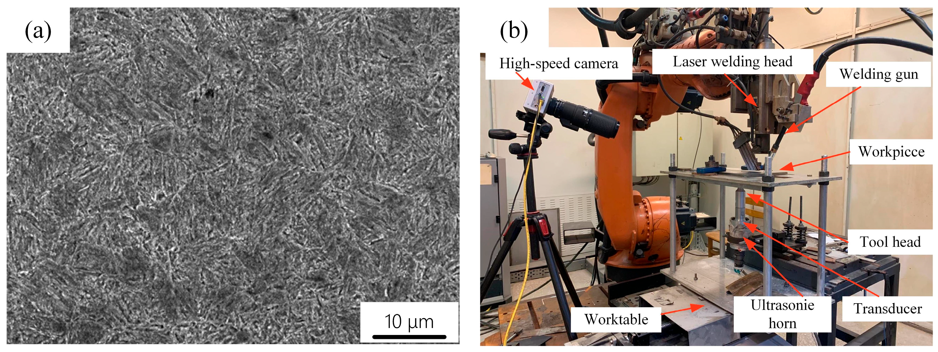
2. Test and Methods
3. Result and Discussion
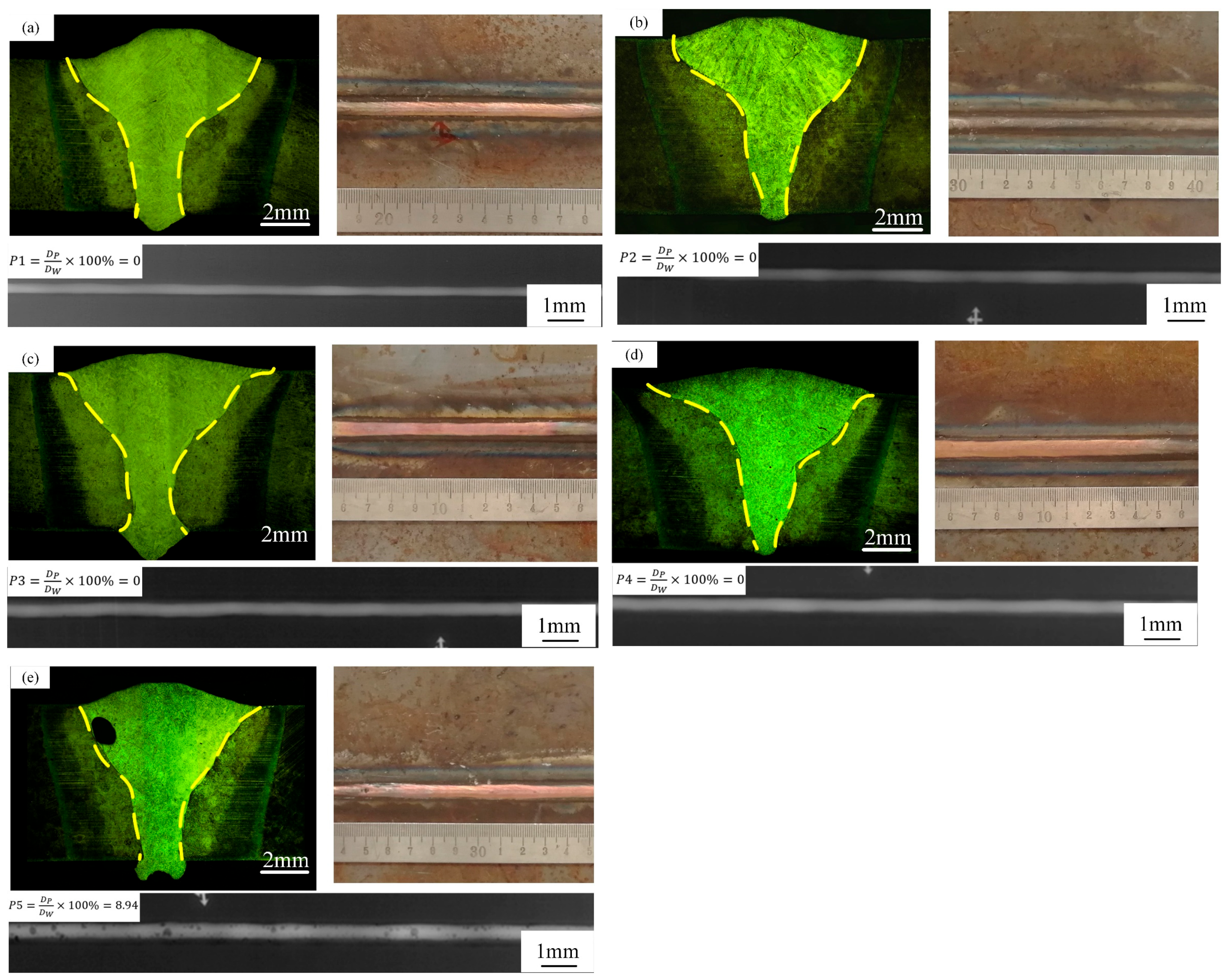
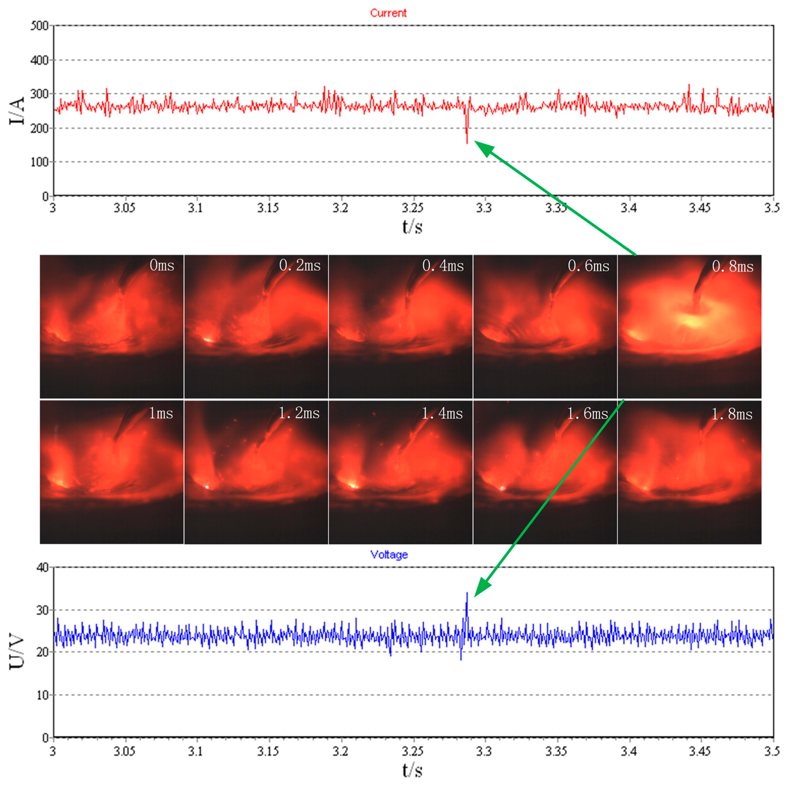
3.1. Effect of Ultrasonic Vibration on Macroscopic Morphology and Porosity Defects of Welds
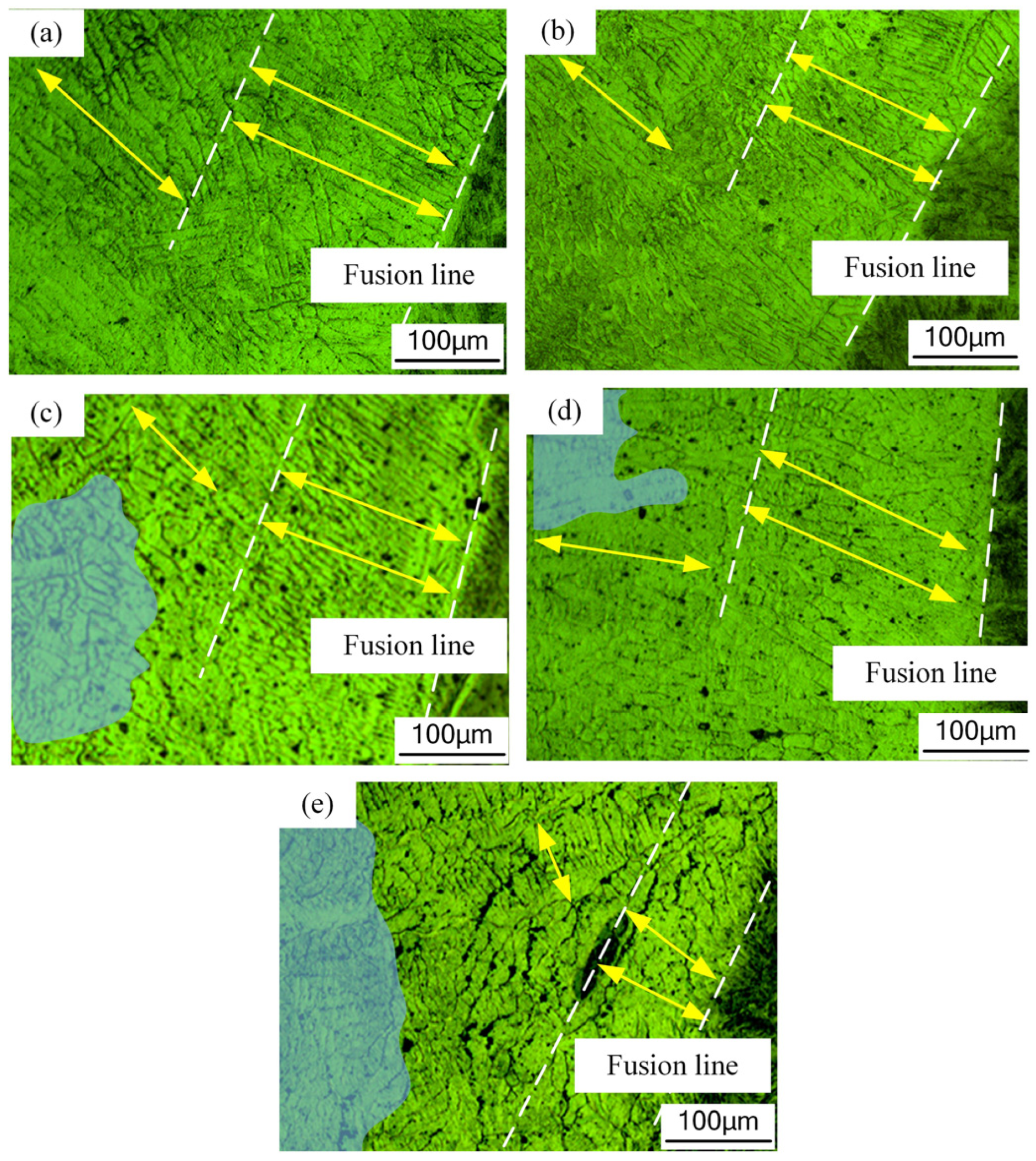
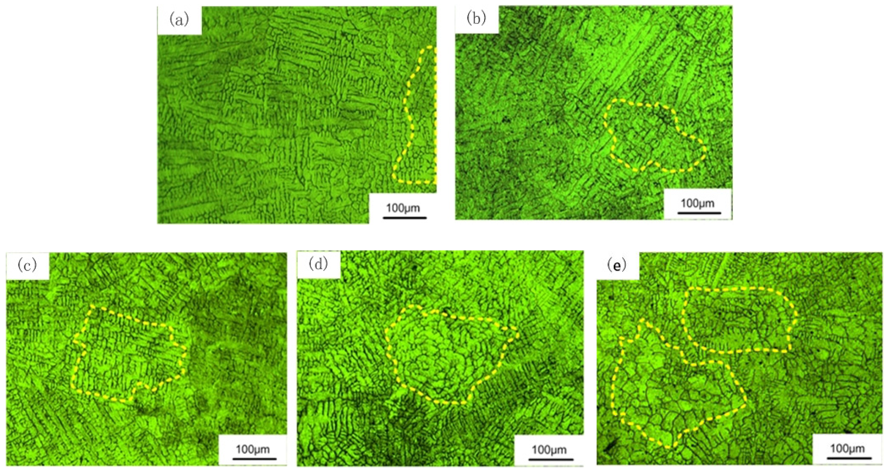
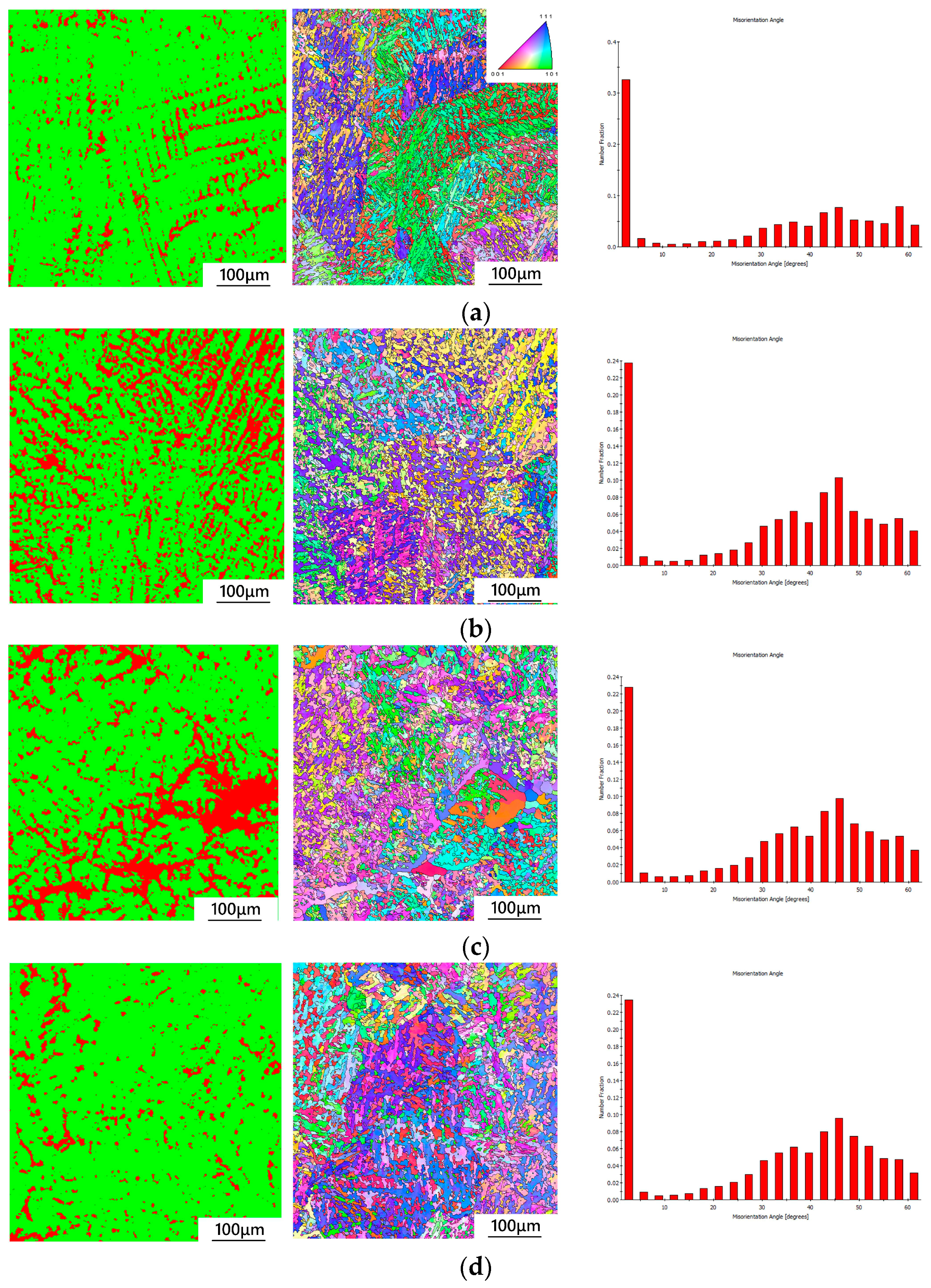
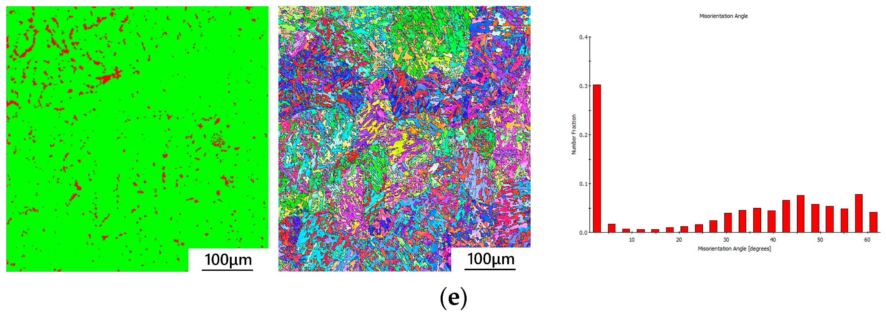
3.2. Effect of Ultrasonic Vibration on Microstructure of Ultra-High-Strength Steel
3.3. Impact of Ultrasonic Vibration on the Mechanical Behavior of Welded Joints
3.3.1. Weld Microhardness Analysis
3.3.2. The Impact of Ultrasonic Vibration on the Stretching Performance of Ultra-High-Strength Steel Joints
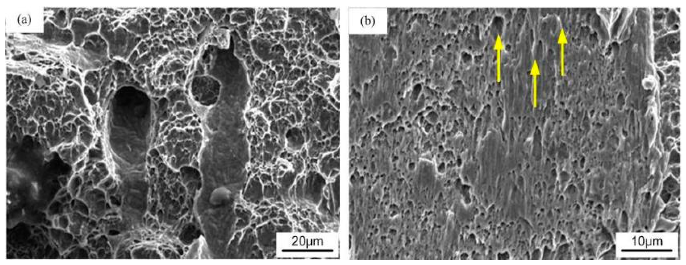
3.3.3. The Influence of Ultrasonic Vibration on the Tensile Behavior of Ultra-High-Strength Steel Welds
4. Conclusions
- As ultrasonic power increases, the weld penetration ratio rises, and the cross-sectional morphology transitions from a “goblet” shape to an “inverted triangle” shape. The distinction between the arc and laser regions becomes less pronounced. However, when ultrasonic power is excessively high, the weld surface becomes irregular and collapses, leading to a deterioration in weld formation quality.
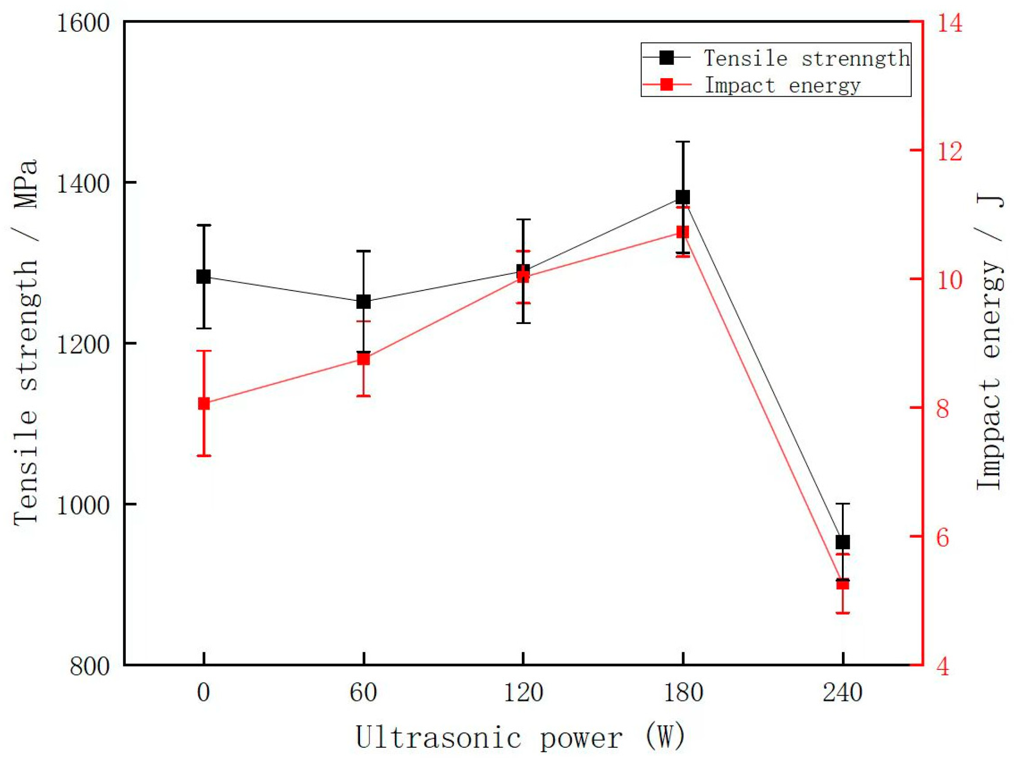
- When the laser power is 2.6 kW, the welding current is 220 A, the welding speed is 0.8 m/min, and the ultrasonic power is 180 W, the maximum tensile strength of the welded joint is 1380 MPa, and the impact power is 10.3 J. The cavitation and acoustic streaming phenomena generated by ultrasound in the laser-arc hybrid welding process refine the grain structure, leading to finer columnar grains and reduced equiaxed grain size. The cavitation effect, induced by ultrasonic vibration, promotes bubble formation and growth, facilitating their upward movement in the molten pool and thereby inhibiting porosity formation. However, at 240 W ultrasonic power, transient cavitation occurs, generating short-lived bubbles. The elevated temperature, intense pressure, and powerful jets resulting from bubble collapse generate numerous tiny bubbles that fail to exit the molten pool promptly, causing porosity.
- As ultrasonic power rises from 0 W to 180 W, the structural integrity of the welded joints enhances. At 180 W ultrasonic power, the weld exhibits high strength and toughness, achieving a tensile strength of 1380 MPa and an impact toughness of 10.5 J.
Author Contributions
Funding
Data Availability Statement
Conflicts of Interest
References
- Li, D.; Wu, H.; Zhan, X.; Chang, Z.; Chen, J. A New Ductile Fracture Model for Edge Cracking Prediction of Ultra-High Strength Steel Considering Damage Accumulation in Blanking Process. J. Mater. Eng. Perform. 2022, 31, 6880–6890. [Google Scholar] [CrossRef]
- Li, X.-Y.; Zhang, Z.-H.; Cheng, X.-W.; Liu, X.-P.; Zhang, S.-Z.; He, J.Y.; Wang, Q.; Liu, L.-J. The investigation on Johnson-Cook model and dynamic mechanical behaviors of ultra-high strength steel M54. Mater. Sci. Eng. A 2022, 835, 142693. [Google Scholar] [CrossRef]
- Zhang, C.; Zhao, Z.; Lin, X.; Wang, S.; Wang, J.; Li, Y.; Li, Y.; Zhang, Y.; Zhao, H. Molybdenum-14Rhenium alloy—The most promising candidate for high-temperature semiconductor substrate materials. J. Alloys Compd. 2024, 991, 174391. [Google Scholar] [CrossRef]
- Cheng, Y.H.; Wu, H.; Zhao, R.G.; Zhou, F. Mechanical characteristics and ballistic behaviors of high strength and hardness armor steels. J. Constr. Steel Res. 2022, 197, 107502. [Google Scholar] [CrossRef]
- Zhang, F.; Qian, K.; Lu, P.; Liu, S.; Lu, S.; Liu, Q.; Cui, B. Quasi-static compressive fracture behavior of three-period minimum surface Al2O3 / Al composites fabricated by stereolithography. J. Mater. Res. Technol. 2024, 30, 4950–4960. [Google Scholar] [CrossRef]
- Morsy, M.A.; Abdel Aziz Sabry, M.; Abdelwahed, K.; Abdelwahab, S.A. Effect of welding parameters on the mechanical and metallurgical properties of armor steel weldment. J. Eng. Appl. Sci. 2022, 69, 62. [Google Scholar] [CrossRef]
- Kostina, V.S.; Kostina, M.V.; Muradyan, S.O.; Kudryashov, A.E. Structure and Properties of the Welded Joints of Rolled Austenitic High-Nitrogen Steel Fabricated by Manual Consumable-Electrode Arc Welding. Russ. Metall. Met. 2022, 2022, 770–777. [Google Scholar] [CrossRef]
- Liu, J.; Zhu, H.; Li, Z.; Cui, W.; Shi, Y. Effect of ultrasonic power on porosity, microstructure, mechanical properties of the aluminum alloy joint by ultrasonic assisted laser-MIG hybrid welding. Opt. Laser Technol. 2019, 119, 105619. [Google Scholar] [CrossRef]
- AlShaer, A.W.; Li, L.; Mistry, A. The effects of short pulse laser surface cleaning on porosity formation and re-duction in laser welding of aluminium alloy for automotive component manufacture. Opt. Laser Technol. 2014, 64, 162–171. [Google Scholar] [CrossRef]
- Atabaki, M.M.; Nikodinovski, M.; Chenier, P.; Ma, J.; Liu, W.; Kovacevic, R. Experimental and numerical in-vestigations of hybrid laser arc welding of aluminum alloys in the thick T-joint configuration. Opt. Laser Technol. 2014, 59, 68–92. [Google Scholar] [CrossRef]
- Zhang, C.; Gao, M.; Wang, D.; Yin, J.; Zeng, X. Relationship between pool characteristic and weld porosity in laser arc hybrid welding of AA6082 aluminum alloy. J. Mater. Process. Tech. 2016, 240, 217–222. [Google Scholar] [CrossRef]
- Hagenlocher, C.; Stritt, P.; Weber, R.; Graf, T. Strain signatures associated to the formation of hot cracks during laser beam welding of aluminum alloys. Opt. Lasers Eng. 2018, 100, 131–140. [Google Scholar]
- Kumar, S.; Wu, C.S.; Padhy, G.K.; Ding, W. Application of ultrasonic vibrations in welding and metal pro-cessing: A status review. J. Manuf. Process. 2017, 26, 295–322. [Google Scholar] [CrossRef]
- Shi, L.; Wu, C.S.; Liu, X.C. Modeling the effects of ultrasonic vibration on friction stir welding. J. Mater. Process. Tech. 2015, 222, 91–102. [Google Scholar]
- Li, X.; Bai, D.; Wang, Y.; Liu, F.; Zhang, H.; Liu, S. High-nitrogen steel laser-hybrid welding in vibration condition. Mater. Sci-Ence Technol. 2019, 36, 434–442. [Google Scholar]
- Cui, B.; Liu, S.; Hua, L.; Luo, T.; Feng, M. Effect of welding heat input on pores in laser-arc hybrid welding of high nitrogen steel. Int. J. Adv. Manuf. Technol. 2021, 119, 421–434. [Google Scholar] [CrossRef]
- Kolubaev, A.V.; Sizova, O.V.; Fortuna, S.V.; Vorontsov, A.V.; Ivanov, A.N.; Kolubaev, E.A. Weld structure of low-carbon structural steel formed by ultra-sonic-assisted laser welding. J. Constr. Steel Res. 2020, 172, 106190. [Google Scholar]
- Nguyen, T.C.; Bui, D.K.; Nguyen, H.L.; Van Nguyen, A.; Nguyen, T.H. Penetration and microstructure of steel joints by ultrasonic-assisted gas metal arc welding. Jpn. J. Appl. Phys. 2022, 61, 046502. [Google Scholar]
- Li, Z.; Xu, Z.; Zhang, H.; Ma, Z.; Chen, S.; Guo, T.; Wen, Q.; Yan, J. Increasing joint strength by achieving carbon fibers continuity with ultrasonic assistance during soldering Cf/Al using ZnAl. Mater. Lett. 2024, 374, 137186. [Google Scholar]
- Wang, B.; Tan, D.; Lee, T.L.; Khong, J.C.; Wang, F.; Eskin, D.; Connolley, T.; Fezzaa, K.; Mi, J. Ultrafast synchrotron X-ray imaging studies of microstructure fragmentation in solidification under ultrasound. Acta Mater. 2018, 144, 505–515. [Google Scholar]
- Zhuang, D.D.; Lian, X.L.; Zhou, T.Y.; Zhang, S.H.; Wang, X.C.; Li, J.; Ding, H.S.; Wang, C. The influence of ultrasonic assistance and laser melting on the microstructure and properties of AZ91D magnesium alloy. Surf. Coat. Technol. 2024, 479, 130541. [Google Scholar]
- ISO 5817:2014; Welding—Fusion-Welded Joints in Steel, Nickel, Titanium and Their Alloys (Beam Welding Excluded)—Quality Levels for Imperfections. International Organization for Standardization: Geneva, Switzerland, 2014.
- ISO 4136:2001; Destructive Tests on Welds in Metallic Materials—Transverse Tensile Test. International Organization for Standardization: Geneva, Switzerland, 2001.
- Song, H.; Zhang, L.; Niu, K.; Petrovna, G.M. Study on Fatigue Performance of Non-Uniform Thickness Markless Laser Lap Welding. J. Phys. Conf. Ser. 2021, 2101, 012009. [Google Scholar]
- Abramov, O.V. High-Intensity Ultrasonics: Theory and Industrial Applications; CRC Press: Boca Raton, FL, USA, 2019. [Google Scholar]
- Yuan, T.; Kou, S.; Luo, Z. Grain refining by ultrasonic stirring of the weld pool. Acta Mater. 2016, 106, 144–154. [Google Scholar]
- Ma, G.; Yan, S.; Wu, D.; Miao, Q.; Liu, M.; Niu, F. Microstructure evolution and mechanical properties of ultrasonic assisted laser clad yttria stabilized zirconia coating. Ceram. Int. 2017, 43, 9622–9629. [Google Scholar]
- Kang, J.; Zhang, X.; Wang, S.; Ma, J.; Huang, T. The comparison of ultrasonic effects in different metal melts. Ultrasonics 2015, 57, 11–17. [Google Scholar]
- Chen, Q.; Lin, S.; Yang, C.; Fan, C.; Ge, H. Grain fragmentation in ultrasonic-assisted TIG weld of pure aluminum. Ultrason. Sonochem. 2017, 39, 403–413. [Google Scholar]


| Chemical Element | C | Si | Mn | Cr | Ni | Mo | Fe |
|---|---|---|---|---|---|---|---|
| HSS | 0.26~0.33 | 0.25~0.44 | 0.75~1.2 | 0.75~1.1 | 1.05~1.40 | 0.25~0.45 | bal. |
| HCr20Ni10Mn7Mo | 0.11 | 0.60 | 0.63 | 20.26 | 11.00 | 1.03 | bal. |
| Welding Parameter | Value |
|---|---|
| Welding speed (m/min) | 0.8 |
| Laser power (kW) | 2.6 |
| Welding current (A) | 220 |
| Arc voltage (V) | 27 |
| Distance between laser and wire (mm) | 5 |
| Defocusing value (mm) | −2 |
| Ultrasonic power (W) | 0 W, 60 W, 120 W, 180 W, 240 W |
Disclaimer/Publisher’s Note: The statements, opinions and data contained in all publications are solely those of the individual author(s) and contributor(s) and not of MDPI and/or the editor(s). MDPI and/or the editor(s) disclaim responsibility for any injury to people or property resulting from any ideas, methods, instructions or products referred to in the content. |
© 2025 by the authors. Licensee MDPI, Basel, Switzerland. This article is an open access article distributed under the terms and conditions of the Creative Commons Attribution (CC BY) license (https://creativecommons.org/licenses/by/4.0/).
Share and Cite
Liang, H.; Shi, X.; Li, Y. Effect of Ultrasonic Assistance on Properties of Ultra-High-Strength Steel in Laser-Arc Hybrid Welding. Coatings 2025, 15, 389. https://doi.org/10.3390/coatings15040389
Liang H, Shi X, Li Y. Effect of Ultrasonic Assistance on Properties of Ultra-High-Strength Steel in Laser-Arc Hybrid Welding. Coatings. 2025; 15(4):389. https://doi.org/10.3390/coatings15040389
Chicago/Turabian StyleLiang, Hua, Xiaolong Shi, and Yanzhou Li. 2025. "Effect of Ultrasonic Assistance on Properties of Ultra-High-Strength Steel in Laser-Arc Hybrid Welding" Coatings 15, no. 4: 389. https://doi.org/10.3390/coatings15040389
APA StyleLiang, H., Shi, X., & Li, Y. (2025). Effect of Ultrasonic Assistance on Properties of Ultra-High-Strength Steel in Laser-Arc Hybrid Welding. Coatings, 15(4), 389. https://doi.org/10.3390/coatings15040389