
Characterization of Additively Manufactured Titanium-Based Alloy with a Micro-Arc Oxidation Coating and Overlying Polyurethane Layer


 ,
,
Abstract
1. Introduction
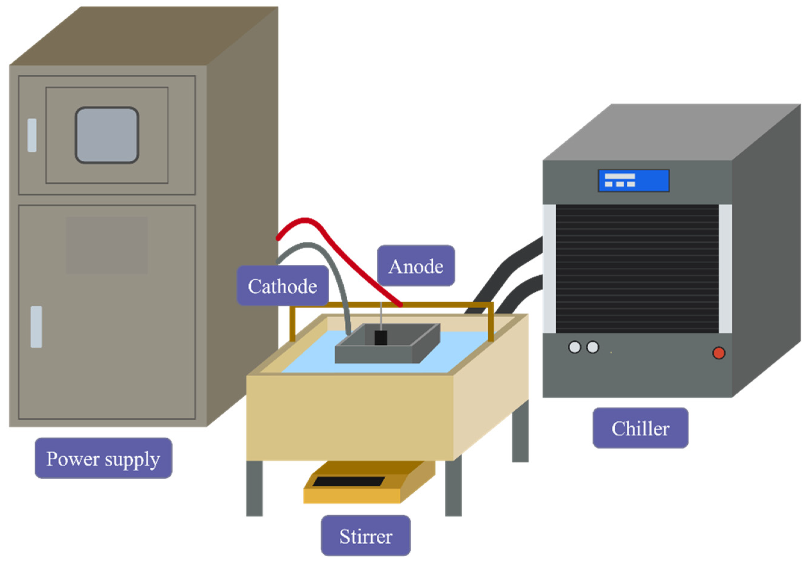
2. Experimental
2.1. Materials and Preparation of Specimens
2.2. Coating Characterization
3. Results
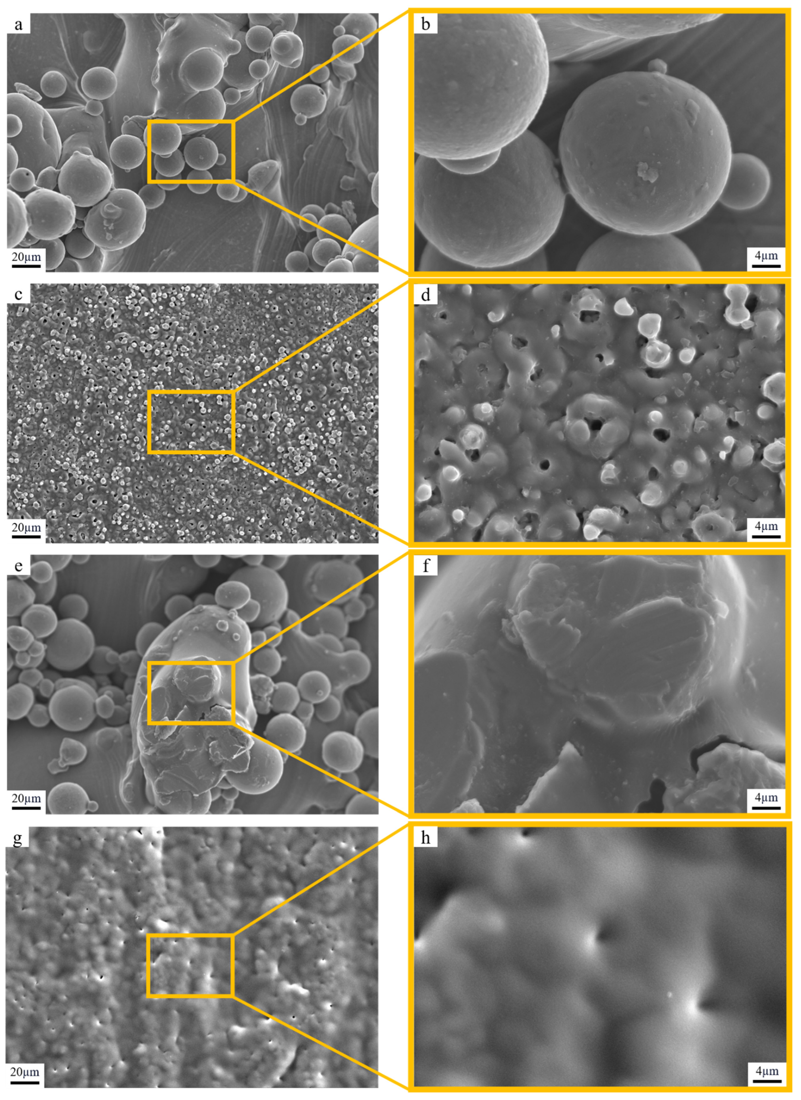
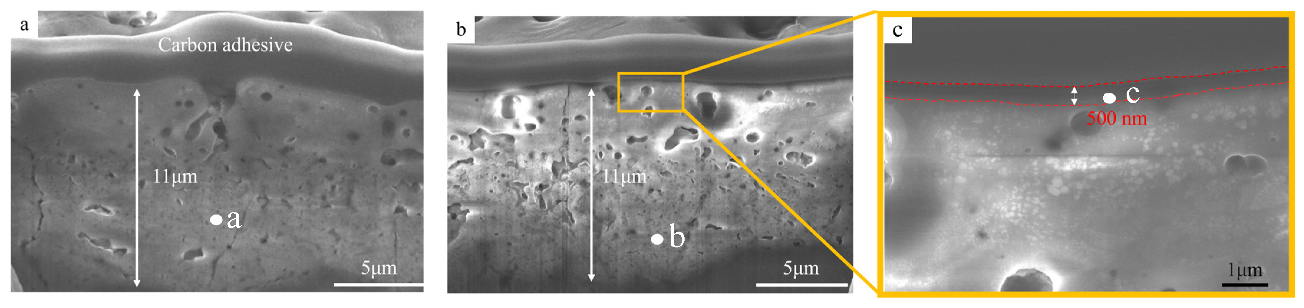
3.1. Morphology Analysis
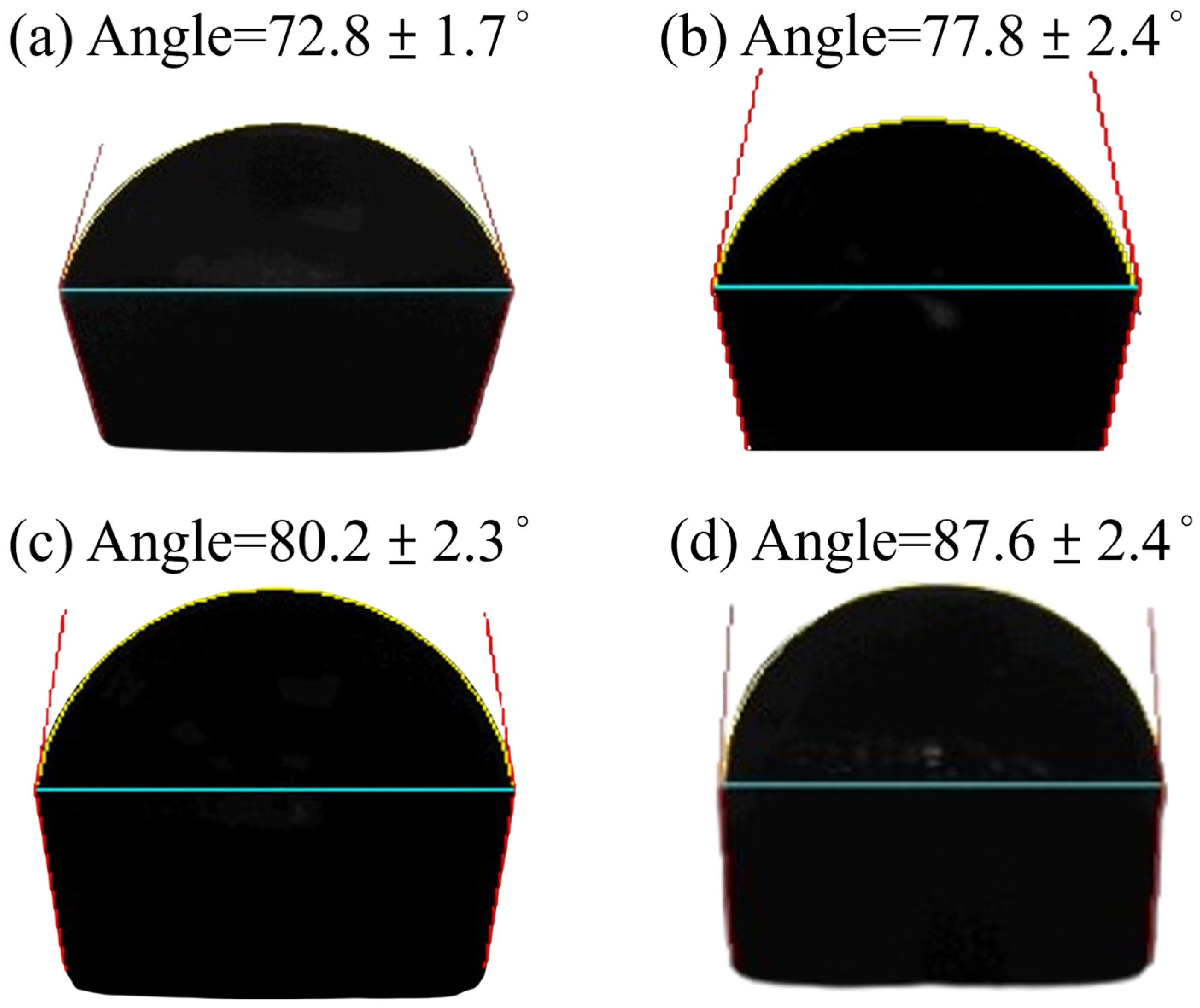
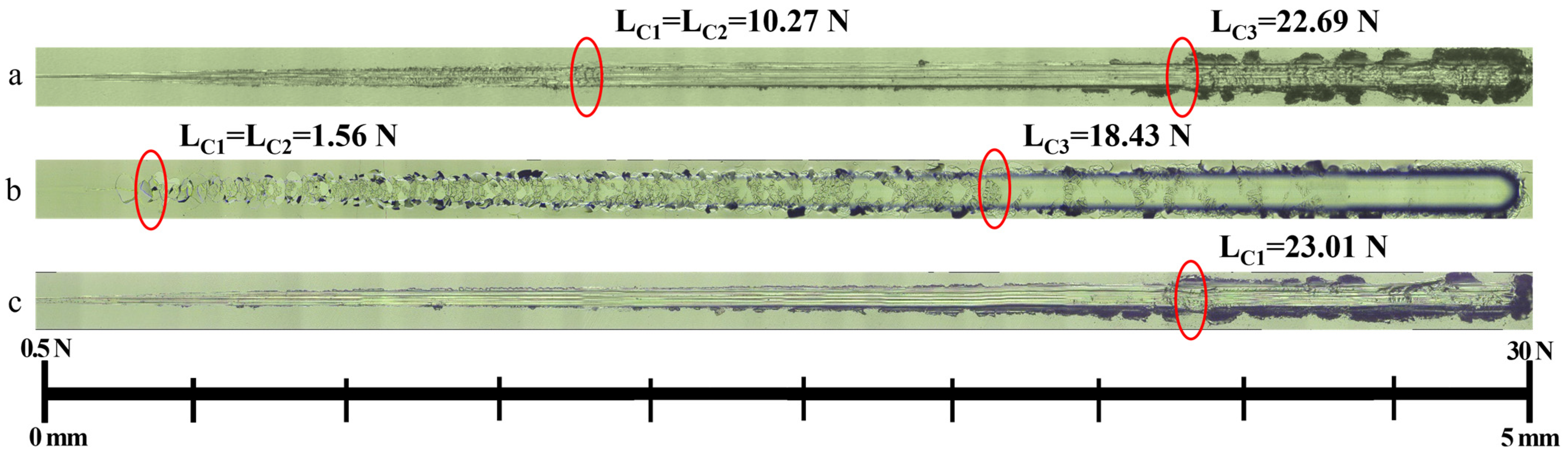
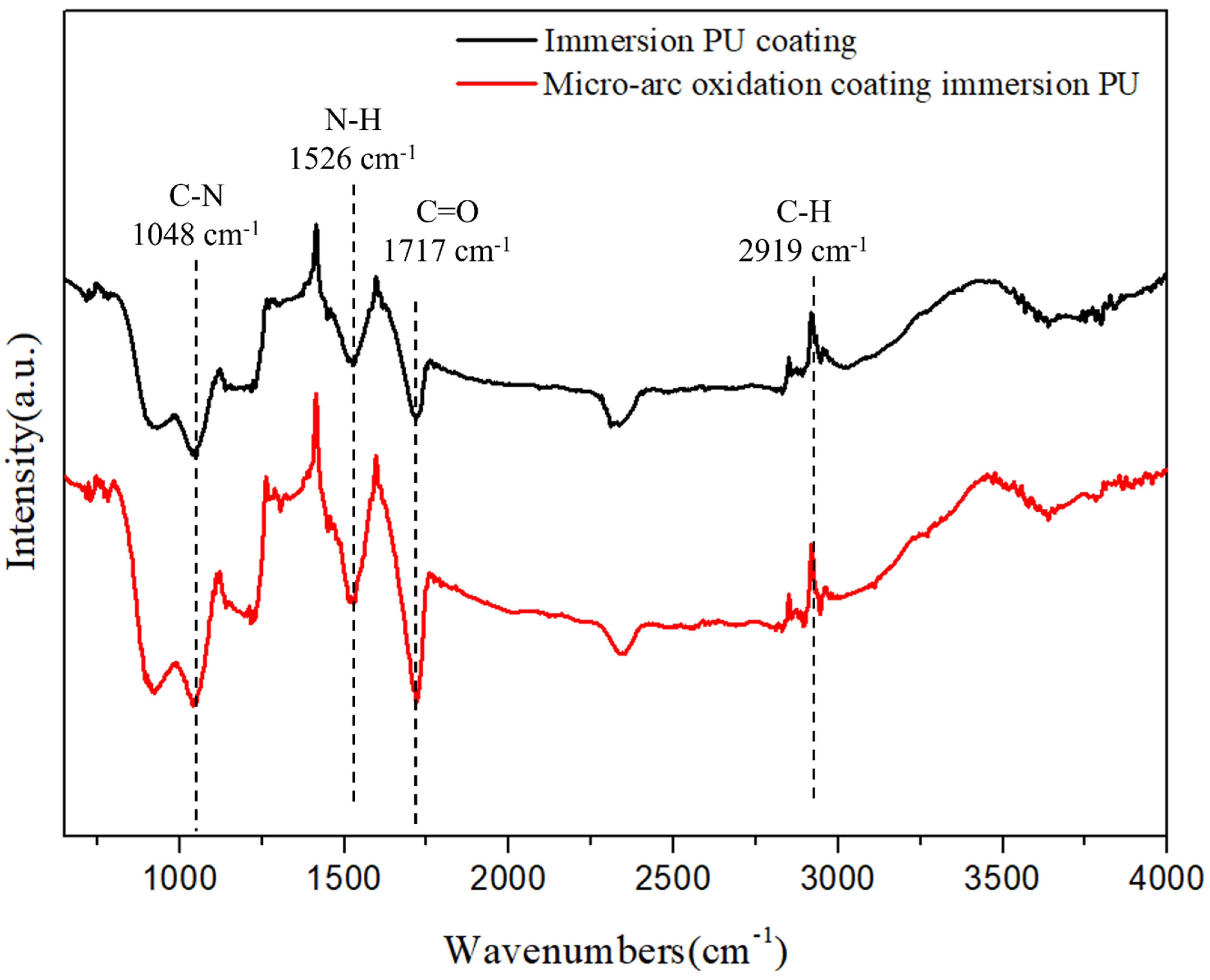
3.2. Properties of MAO Coating with a PU Layer
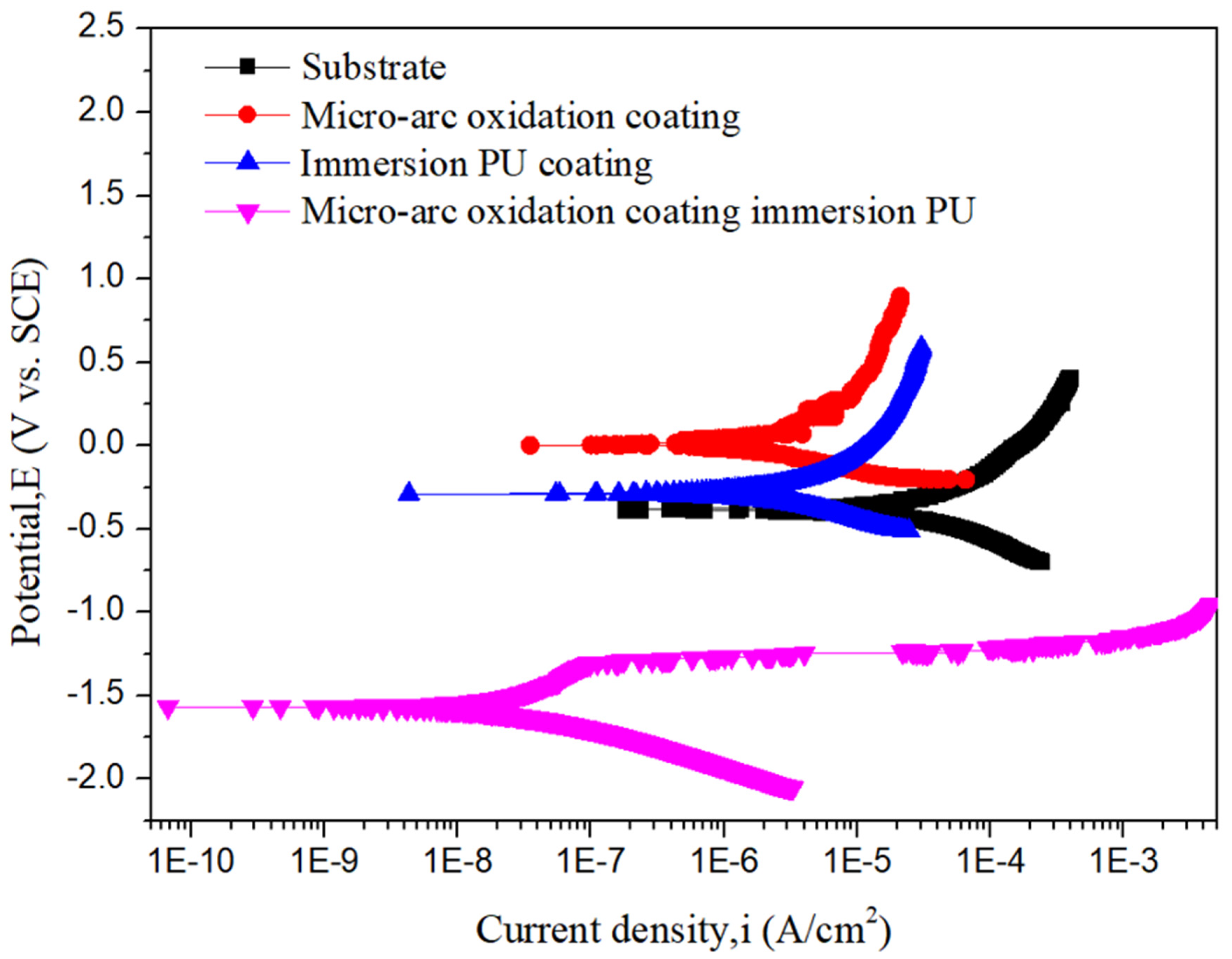
3.3. Corrosion Resistance Test
4. Conclusions
Author Contributions
Funding
Institutional Review Board Statement
Informed Consent Statement
Data Availability Statement
Conflicts of Interest
References
- Li, G. Review of micro-arc oxidation of titanium alloys: Mechanism, properties and applications. J. Alloys Compd. 2023, 948, 169773. [Google Scholar] [CrossRef]
- Zhong, S.; Li, G.; Zhang, S.; Zhao, R.; Jiang, X.; Zhang, R. Preparation and formation mechanism of anodic coatings co-doped with Ga, Si, and P ions on Ti–6Al–4V alloys. Mater. Chem. Phys. 2022, 282, 125923. [Google Scholar] [CrossRef]
- Alves, A.C. Effect of bio-functional MAO layers on the electrochemical behaviour of highly porous Ti. Surf. Coat. Technol. 2020, 386, 125487. [Google Scholar] [CrossRef]
- Zhang, Y.; Chen, F.; Zhang, Y.; Liu, M.; Pang, Y.; Du, C. Microstructure and corrosion resistance of duplex coatings deposited on TC17 alloys by MAO and HiPIMS. Mater. Lett. 2021, 303, 130506. [Google Scholar] [CrossRef]
- Liao, S.-C.; Chang, C.-T.; Chen, C.-Y.; Lee, C.-H.; Lin, W.-L. Functionalization of pure titanium MAO coatings by surface modifications for biomedical applications. Surf. Coat. Technol. 2020, 394, 125812. [Google Scholar] [CrossRef]
- Saeed, E.M.; Dawood, N.M.; Hasan, S.F. Improvement corrosion resistance of Ni-Ti alloy by TiO2 coating and hydroxyaptite/TiO2 composite coating using micro arc oxidation process. Mater. Today Proc. 2021, 42, 2789–2796. [Google Scholar] [CrossRef]
- Li, S.; Hou, Y.; Huang, J.; Shi, J.; Meng, L. Exploring the enhanced energy-absorption performance of hybrid polyurethane(PU)-foam-filled lattice metamaterials. Int. J. Impact Eng. 2024, 193, 105058. [Google Scholar] [CrossRef]
- Zhang, Z. Combined modification of asphalt with organic attapulgite (OATT) and polyurethane (PU): Preparation, properties and modification mechanisms. Constr. Build. Mater. 2023, 406, 133435. [Google Scholar] [CrossRef]
- Xu, L.; Li, X.; Jiang, F.; Yu, X.; Wang, J.; Xiao, F. Thermosetting characteristics and performances of polyurethane material on airport thin-overlay. Constr. Build. Mater. 2022, 344, 128252. [Google Scholar] [CrossRef]
- Liu, H. Modification of asphalt using polyurethanes synthesized with different isocyanates. Constr. Build. Mater. 2022, 327, 126959. [Google Scholar] [CrossRef]
- Wang, Y.; Yu, H.; Chen, C.; Zhao, Z. Review of the biocompatibility of micro-arc oxidation coated titanium alloys. Mater. Des. 2015, 85, 640–652. [Google Scholar] [CrossRef]
- Kuroda, P.A.B.; de Mattos, F.N.; Grandini, C.R.; Afonso, C.R.M. Micro-abrasive wear behavior by ball cratering on MAO coating of Ti–25Ta alloy. J. Mater. Res. Technol. 2023, 26, 1850–1855. [Google Scholar] [CrossRef]
- Xi, F.; Zhang, X.; Kang, Y.; Wen, X.; Liu, Y. Mechanistic analysis of improving the corrosion performance of MAO coatings on Ti-6Al-4V alloys by annealing. Surf. Coat. Technol. 2024, 476, 130264. [Google Scholar] [CrossRef]
- Buyuksungur, S.; Parau, A.C.; Dinu, M.; Pana, I.; Vitelaru, C.; Schmidt, J.; Tanir, T.E.; Hasirci, V.; Vladescu, A.; Hasirci, N. Variations of chemical, physical, mechanical properties, and biological and antimicrobial effectiveness of Ti alloys by coating with CaP doped with different amounts of Zn via micro-arc oxidation (MAO) technique. Ceram. Int. 2024, 50, 37096–37110. [Google Scholar] [CrossRef]
- Yang, W.; Gao, Y.; Guo, P.; Xu, D.; Hu, L.; Wang, A. Adhesion, biological corrosion resistance and biotribological properties of carbon films deposited on MAO coated Ti substrates. J. Mech. Behav. Biomed. Mater. 2020, 101, 103448. [Google Scholar] [CrossRef]
- Torrento, J.E. Bulk and surface design of MAO-treated Ti-15Zr-15Mo-Ag alloys for potential use as biofunctional implants. Mater. Lett. 2020, 269, 127661. [Google Scholar] [CrossRef]
- Xie, Y. Effect of micro-arc oxidation on antimicrobial properties and biocompatibility of biomedical Ti-xFe alloys. Surf. Coat. Technol. 2024, 476, 130174. [Google Scholar] [CrossRef]
- Kang, B.; Chen, X.; Qi, S.; Ma, F.; Liu, P. Characteristics of novel Ti–40Nb-xCu alloy and surface treatment with superior antibacterial property and biocompatibility using micro-arc oxidation for dental implants. J. Mech. Behav. Biomed. Mater. 2024, 157, 106605. [Google Scholar] [CrossRef]
- Guo, C. Preparation and corrosion resistance characterization of MAO coating on AZ31B magnesium alloy formed in the mixed silicate and phosphate electrolytes with pectin as an additive. Surf. Coat. Technol. 2024, 476, 130209. [Google Scholar] [CrossRef]
- Qian, L. Biodegradable PTMC-MAO composite coatings on AZ31 Mg-alloys for enhanced corrosion-resistance. J. Alloys Compd. 2024, 998, 175017. [Google Scholar] [CrossRef]
- Chen, Y. Effect of solution pH value on the corrosion resistance of Co-Fe LDHs coating developed on MAO treated magnesium alloy AZ31. Colloids Surf. Physicochem. Eng. Asp. 2024, 694, 134220. [Google Scholar] [CrossRef]
- Lee, H.-B.; Sheu, H.-H.; Jian, J.-S.; Hsiao, R.-C. Study on the Characteristics of MAO/Polymer/Ni Three-Layer Composite Film formed on AZ31 Magnesium Alloy. Int. J. Electrochem. Sci. 2021, 16, 211246. [Google Scholar] [CrossRef]
- Li, Y.; Sun, R. Enhanced corrosion resistance and photothermal antibacterial properties of MAO/Fe/GO composite coating on Mg alloy. Mater. Lett. 2024, 369, 136755. [Google Scholar] [CrossRef]
- Li, F.; Sun, R.; Chen, K.; Gao, H. Improvement in adhesion and corrosion resistance of Ce-based coating on micro-arc oxidized AZ31B Mg alloy via employing graphene oxide as an effective interlayer. Mater. Today Commun. 2024, 40, 109862. [Google Scholar] [CrossRef]
- Arslan, E.; Totik, Y.; Demirci, E.E.; Efeoglu, I. Wear and adhesion resistance of duplex coatings deposited on Ti6Al4V alloy using MAO and CFUBMS. Surf. Coat. Technol. 2013, 214, 1–7. [Google Scholar] [CrossRef]
- Qi, X.; Gao, H.; He, Y.; Su, X.; Song, R. Microstructure and properties of a MAO/PA/MoS2 composite coating formed on 6063 aluminum alloy by micro arc oxidation. Surf. Coat. Technol. 2024, 484, 130836. [Google Scholar] [CrossRef]
- Li, B. Mao-based solid-like slippery composite coating with superior corrosion resistance and robust machinery performance upon magnesium-lithium alloy LA81. Chem. Eng. J. 2024, 497, 154801. [Google Scholar] [CrossRef]
- Chen, Q.; Zhu, X.; Jiang, Y.; Yang, L.; Liu, H.H.; Song, Z. Development and characterization of MAO/PLA-nHA nanocomposite coatings on pure zinc for orthopedic applications. Surf. Coat. Technol. 2024, 478, 130452. [Google Scholar] [CrossRef]
- Jin, L.; Li, Y.; Liu, C.; Fan, X.; Zhu, M. Friction mechanism of DLC/MAO wear-resistant coatings with porous surface texture constructed in-situ by micro-arc oxidation. Surf. Coat. Technol. 2023, 473, 130010. [Google Scholar] [CrossRef]
- Zhang, S.; Guo, W.; Liu, N.; Xia, C.; Wang, H.; Liang, C. In situ preparation of MAO/TiO2 composite coating on WE43 alloy for anti-corrosion protection. Vacuum 2022, 197, 110835. [Google Scholar] [CrossRef]
- Drelich, J.W.; Boinovich, L.; Chibowski, E.; Volpe, C.D.; Hołysz, L.; Marmur, A.; Siboni, S. Contact angles: History of over 200 years of open questions. Surf. Innov. 2020, 8, 3–27. [Google Scholar] [CrossRef]


| Electrolyte Formula | Na2SiO3 | NaH2PO2 | NaOH | NaF |
|---|---|---|---|---|
| Concentration | 0.049 M | 0.035 M | 0.035 M | 0.035 M |
| Operating Parameters | Voltage (V) | Frequency (Hz) | Temperature (°C) | Time (s) |
|---|---|---|---|---|
| Value | 430 | 50 | below 15 | 600 |
| Point | Element–Atomic% | |||||||
|---|---|---|---|---|---|---|---|---|
| O | Ti | Si | F | P | C | N | Total | |
| a | 58.1 ± 5.2 | 28.3 ± 3.7 | 5.5 ± 0.9 | 5.2 ± 0.3 | 2.9 ± 0.1 | – | – | 100 |
| b | 57.6 ± 4.4 | 28.5 ± 3.1 | 5.9 ± 0.8 | 4.6 ± 0.2 | 3.4 ± 0.3 | – | – | 100 |
| c | 19.1 ± 3.6 | – | – | – | – | 69.6 ± 6.8 | 11.3 ± 3.2 | 100 |
| Substrate | MAO Coating | Immersion PU Coating | MAO Coating Immersion PU | |
|---|---|---|---|---|
| Ecorr (VSCE) | −0.38 V | −0.16 V | −0.29 V | −1.56 V |
| icorr (µA/cm2) | 1.06 × 10⁻⁵ | 1.11 × 10⁻⁶ | 1.31 × 10⁻⁶ | 1.91 × 10⁻⁸ |
Disclaimer/Publisher’s Note: The statements, opinions and data contained in all publications are solely those of the individual author(s) and contributor(s) and not of MDPI and/or the editor(s). MDPI and/or the editor(s) disclaim responsibility for any injury to people or property resulting from any ideas, methods, instructions or products referred to in the content. |
© 2025 by the authors. Licensee MDPI, Basel, Switzerland. This article is an open access article distributed under the terms and conditions of the Creative Commons Attribution (CC BY) license (https://creativecommons.org/licenses/by/4.0/).
Share and Cite
Lien, P.-W.; Jian, S.-Y.; Hung, J.-C.; Yang, P.-J.; Lin, H.-H.; Chu, K.-Y.; Kao, C.-H.; Ferng, Y.-C.; Huang, S.-H.; Jen, K.-K. Characterization of Additively Manufactured Titanium-Based Alloy with a Micro-Arc Oxidation Coating and Overlying Polyurethane Layer. Coatings 2025, 15, 137. https://doi.org/10.3390/coatings15020137
Lien P-W, Jian S-Y, Hung J-C, Yang P-J, Lin H-H, Chu K-Y, Kao C-H, Ferng Y-C, Huang S-H, Jen K-K. Characterization of Additively Manufactured Titanium-Based Alloy with a Micro-Arc Oxidation Coating and Overlying Polyurethane Layer. Coatings. 2025; 15(2):137. https://doi.org/10.3390/coatings15020137
Chicago/Turabian StyleLien, Po-Wei, Shun-Yi Jian, Jung-Chou Hung, Po-Jen Yang, Hsuan-Han Lin, Kuan-Yu Chu, Chun-Hsiang Kao, Yi-Cherng Ferng, Sheng-Hsiang Huang, and Kuo-Kuang Jen. 2025. "Characterization of Additively Manufactured Titanium-Based Alloy with a Micro-Arc Oxidation Coating and Overlying Polyurethane Layer" Coatings 15, no. 2: 137. https://doi.org/10.3390/coatings15020137
APA StyleLien, P.-W., Jian, S.-Y., Hung, J.-C., Yang, P.-J., Lin, H.-H., Chu, K.-Y., Kao, C.-H., Ferng, Y.-C., Huang, S.-H., & Jen, K.-K. (2025). Characterization of Additively Manufactured Titanium-Based Alloy with a Micro-Arc Oxidation Coating and Overlying Polyurethane Layer. Coatings, 15(2), 137. https://doi.org/10.3390/coatings15020137