Article

Improved Tribological Properties of Blanking Punches for Copper Alloys Utilizing Deterministic Surface Texturing by Machine Hammer Peening

Institute for Production Engineering and Forming Machines (PtU), Technical University of Darmstadt, Otto-Berndt-Strasse 2, 64287 Darmstadt, Germany
*
Author to whom correspondence should be addressed.
Coatings 2025, 15(2), 136; https://doi.org/10.3390/coatings15020136
Submission received: 27 November 2024 / Revised: 15 January 2025 / Accepted: 23 January 2025 / Published: 24 January 2025

Abstract

:
Constant efforts to increase resource efficiency, productivity, and output quantities, as well as growing product requirements, result in high tribological loads on forming tools. The manipulation of the tribological properties of blanking punches by deterministic texturing using machine hammer peening on the lateral surface is a solution to ensure an extended service life. For this purpose, rotationally symmetrical blanking punches were textured using a specially developed texturing center. The machine hammer peening center allows surface texturing with positioning accuracies of less than 2% for individual indentations by controlling a rotary and feed axis in combination with frequency control of the machine hammer peening setup. A modified hammer head with a micro-tip was used as the texturing tool. Different coverage ratios with the same aspect ratio were applied to the surface. These punches were then tested on an industrial high-speed press. To evaluate the effectiveness, the force curves were analyzed and the evolution of the textured topography was continuously evaluated. The experiments showed that the withdrawal force could be reduced by 38% due to microtexturing with a coverage ratio of 18%. Other coverage ratios resulted in an increase. By texturing the lateral surfaces of blanking punches using machine hammer peening, the service life was also significantly improved.

Graphical Abstract

1. Introduction

As part of the global trends of the digitization of products [1], the increasing automation of industry [2], and the electrification of automotive powertrains [3] while shortening the life cycles of electrical consumables [4], the demand for electrically conductive blanking products, such as copper alloys, is constantly increasing [5,6]. The drive towards miniaturization and the desire for functional integration in individual components leads to a growing complexity in product design [7,8]. This results in complex blanking contours of blanked products, which inherit challenging tribological load collectives [9]. Despite the comparatively low strength of the processed copper alloys, these demanding geometries result in a reduced tool life due to increased wear [10]. The occurring wear affects the forming results, the process limits, and the tool life in sheet-metal working processes such as deep-drawing and blanking [11]. Lubricants are often used to compensate for these effects [12]. The use and performance of friction-reducing lubricants, such as additives, are thus strongly inhibited [13], and their performance is constantly under review [14,15,16]. National and international legal requirements like the REACH regulation of the European Parliament further strictly limits the use of lubricants and places high demands on environmentally compatible reprocessing after use [17]. Approaches are therefore needed to optimize tribological behavior without the need for additional lubricants.
Due to this fact, several processes to modify the surface properties that prolong tool life are used, like hardening of punches [18], hard coatings such as PVD and CVD [19], or systematic rounding of the punch edge radii [20,21]. These processes make a significant contribution to inhibiting progressive abrasive wear, delaying, for instance, the rounding of the edge radii of blanking punches. However, the effect on wear due to adhesion is relatively small. It has been shown that the tribological properties of sheet metal processing tools can be significantly improved by modifying the surface through microtexturing. With the use of microtexturing, consisting of deterministically arranged individual cavities, wear-provoking effects such as adhesion or abrasion can be inhibited [22]. Due to the resulting deterministic texture of vibration-assisted ball burnishing (VABB), Velazquez-Corral et al. were able to demonstrate a 39.4% reduction in friction and a 15.9% in wear compared with conventional ball burnishing investigated on a custom tribometer [23]. Saeidi et al. showed, for a setup on an oscillating tribometer, that the resulting wear particles are transported out of the forming zone by means of an insertion ring in the cavities [24]. Shimizu et al. demonstrated, for a deep drawing process, that surface modification contributes to the activation of fluid mechanical effects, which reduces the coefficient of friction (COF). In addition, lubricant is fed into the forming zone via the cavities. This facilitates targeted lubrication in tribologically relevant zones [25]. Kitamura et al. were able to utilize these effects for the first time by laser texturing the lateral surface of blanking punches to reduce the friction force [26].
To enhance the tribological performances of blanking tools for boundary and mixed friction, this study considers the manipulation of frictional behavior by microtexturing with machine hammer peening (MHP). MHP is used for smoothing technical surfaces, inducing residual compressive stresses, and work hardening in the surface layer of the tool [27,28,29]. Using modified hammer heads with micromilled tips, cavities that serve as lubricant pockets and particle reservoirs were applied by Steitz et al. onto strip drawing tools in the same process step [30]. The beneficial effects on tool surfaces will be analyzed using the example of high-speed blanking as a representative sheet metal forming process. Therefore, rotational symmetric blanking punches will be textured.

2. Objective

Microtexturing by MHP can contribute to a significant increase in tribological performance for tribosystems used in sheet metal forming [31,32]. The authors were able to show that a large variety of texturing parameters determines the efficacy of the surface modification, depending on the tribological system and load under consideration [33]. In order to test the suitability of the technology for rotationally symmetrical blanking punches, it is necessary to apply textures to the lateral surface in a reproducible manner by varying selected texturing parameters such as aspect ratio A R , indentation distance a i , and coverage ratio α .
For this reason, the authors developed a special texturing cell for automated texturing using MHP. Following the successful application of the punch surface, the properties achieved for the various texture variants are evaluated with an otherwise constant tribological system in the real process on a high-speed press. A friction-sensitive combination of sheet material, lubricant, and blanking clearance is considered for the economic evaluation of the wear behavior. The evaluation of the resulting process performance and wear behavior is based on optical microscopy and process data. Figure 1 visualizes the described methodology.

3. Materials and Methods

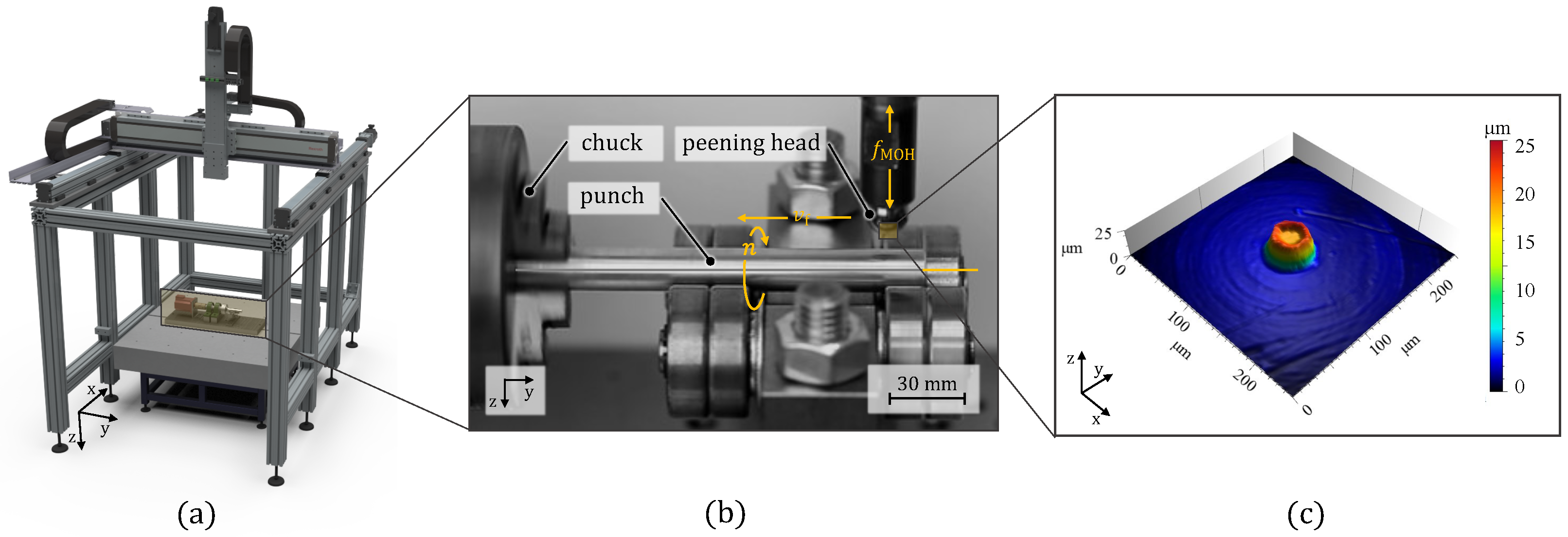
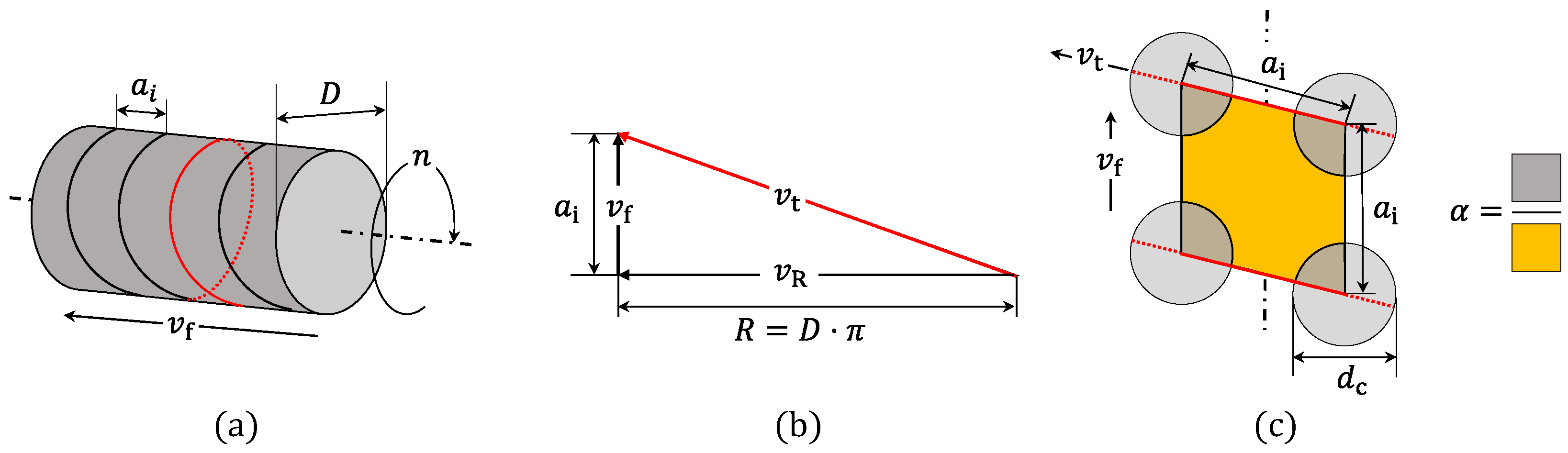
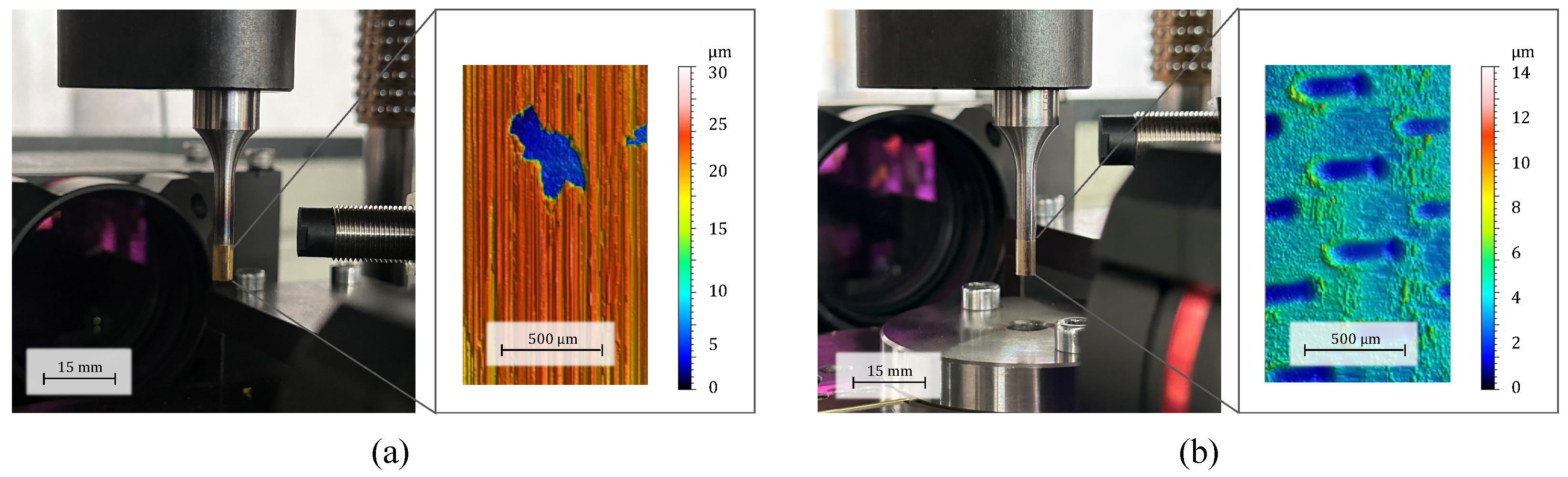
3.1. Microtexturing Cell
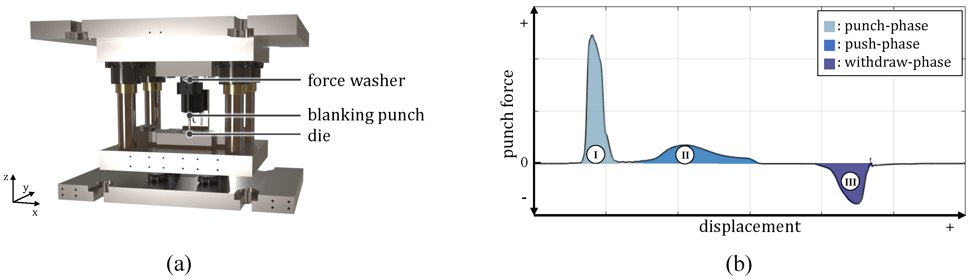
The electromechanical MHP system used in this work from Accurapuls GmbH (Lippetal, Germany) allows targeted control of the impact frequency f i and the impact energy P i . In previous work, the texturing of the lateral surface was performed on a three-axis CNC. To achieve this, the punch was clamped, several paths of the lateral surface were textured, and finally, the punch was rotated until the entire perimeter was textured [31]. This approach has already demonstrated the potential of texturing. The integration of the rotational axis into the CNC machinery, the implementation of synchronous feed control, and the optimization of microtip quality were identified as the factors that served to restrict the potential for advancement. However, the reproducibility and processing efficiency, as well as the load on the microtip due to the multiaxial load in particular, offered potential for optimization.
To confront the described issues, a texturing center with kinematics comparable to a lathe machine is used to apply the texture to rotationally symmetrical punches. The MHP system is guided along the surface contour of the rotation axis via a feed axis at a defined ratio of speed and distance. An additional rotary axis ensures that the entire lateral surface of the punch is machined. A microturned microtip on the peening head embosses cavities on the machined surface (see Figure 2).
This results in a spiral-shaped processing trajectory. Defined indentation distances ( a i ) can be set by controlling the impact frequency of the MHP system ( f i ), as well as the feed rate ( v f ) and rotational speed (n) of the machining axis. Figure 3 shows the resulting kinematic and geometric relationships for the texturing of rotationally symmetrical tools using MHP. The ratio of the total area of the applied cavities to the initial tool surface is referred to as the coverage ratio and is decisive for the influence achieved on the friction properties [34]. The coverage ratio α can be calculated as follows (see Figure 3c):
α = π · d c 2 4 · a i 2
Based on the requirement of constant indentation distances along the trajectory and the axis of rotation, the indentation distance a i must be covered with each revolution. The speed along the trajectory v t can be formulated as follows, using the relationship shown in Figure 3:
v t 2 = v f 2 + v R 2 = n · a i 2 + n · π · D 2
Furthermore, v t can also be described as the product of the indentation frequency f i and the indentation distance a i . By equating both conditions to the trajectory speed, the revolution speed can be resolved as follows:
n = a i · f i 2 π · D 2 + a i 2
Industrial blanking punches from Dayton Progress GmbH (Frankfurt, Germany) with a shaft diameter of 4 and 6 mm and a hardness of 45 HRC were textured. Based on the findings of the tribometer studies carried out, the punch surfaces were textured with α of 15%, 18%, and 20% [33]. Based on preliminary investigations, an average diameter d c of 130 µm was assumed for the cavities resulting from the indentations. This was used to calculate the desired coverage ratios. Using Equations (2) and (3), the rotational speed and feed speed were calculated. Therefore, the indentation frequency f i and power P i were kept constant. In addition, a punch without a microtip was processed by simple MHP for smoothing. This is indicated with α = 0 % . To prevent damage to the edge radius during texturing, the texture is applied at a distance of 1 mm from the edge radius. A length of 10 mm is textured. Table 1 summarizes the parameters used to texture the punches.

3.2. Blanking

The punches are tested in the blanking process to evaluate the properties achieved by texturing. All experiments were performed on a high-speed press type BSTA 810 from Bruderer AG (Frasnacht, Switzerland). The machine parameters for the experiments were set to a stroke distance of 61 mm and a stroke speed of 300 strokes per minute (spm). To shift the focus of the blanking process to the push and withdraw phase, where lateral surface and sheet are in contact, the punches with a diameter of 6 mm immerse 7.4 mm into the die. For an additional, particularly wear-sensitive, service life analysis of the lateral surface modification, the immerse depth d i was increased to 9 mm and the stroke rate to 600 spm for the 4 mm blanking punch. This results in higher relative speeds in the process and longer contact between the punch and the sheet metal. Consequently, the load on the punch increases considerably, resulting in accelerated wear. The material employed in this study was a cold-rolled copper alloy. As no supplementary lubrication was utilized, the only source of lubrication available for the blanking operation was the residual lubricant from the manufacturing of the sheet metal strip. According to technical conditions of supply in the automotive industry, an average lubrication quantity of 1 ± 0.25 g · mm 2 is assumed. Table 2 summarizes the mechanical properties.
As shown in Figure 4a, the force signals are measured with an uniaxial force washer of type 9054A from Kistler Instrumente AG (Winterthur, Switzerland), integrated into the upper part of the tool for force measurement. The signal is digitized with the analog acquisition module NI 9201 ± 10 V by National Instruments AG (Austin, TX, USA)) using a sampling frequency of 20 kHz. The measured force curve is characterized by three phases, as shown in Figure 4b. During the punch phase (I), the tool hits the sheet and starts to elastically deform the material. Thus, the material behavior changes from a linear elastic phase to a plastic deformation until the stresses in the forming zone exceed the maximum shear strength. At this point, shearing stresses exceed the shear fracture limit and the material begins to break abruptly, releasing the stored elastic energy to the system. During the push phase (II), the blanked workpiece is pushed out of the die and the punch passes through the bottom dead center. Finally, in the withdraw phase (III), the punch is pulled out of the die, leading to withdrawal forces that result from a clamping between sheet and punch.

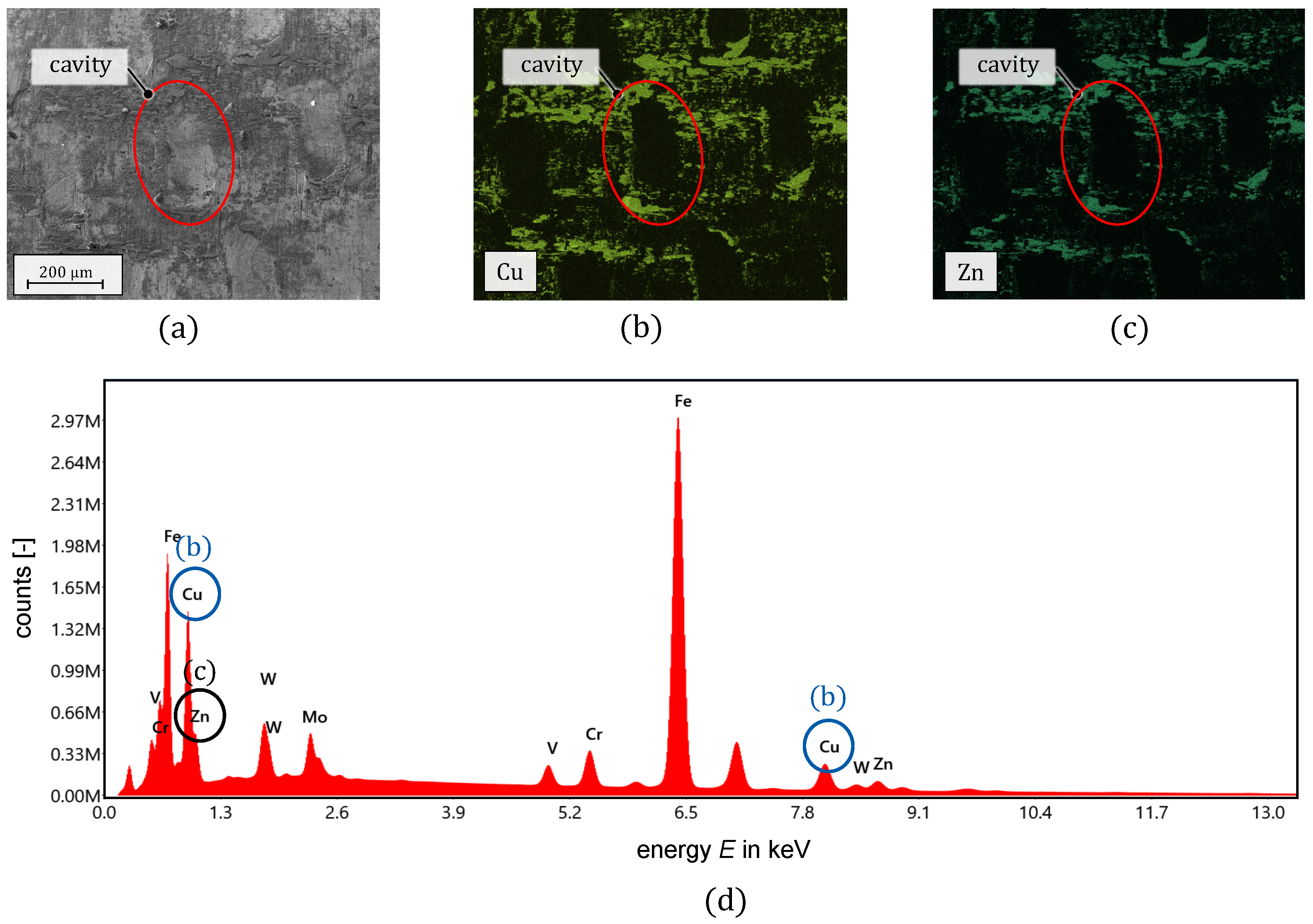
3.3. Microscopic Surface and EDX Analysis

Finally, confocal microscopy and scanning electron microscopy (SEM) analysis were performed to analyze the resulting topographies and evaluate specific wear phenomena. The confocal microscope used is an µ Surf expert by NanoFocus AG (Oberhausen, Germany) equipped with a 20× magnifying lens. For the SEM images a MIRA3-XM by TESCAN Group (Brno, Czech Republic) equipped with an energy-dispersive X-ray spectrometer (SEM–EDX) was used. Typical working parameters are an accelerating voltage of 20 kV and a working distance of 10 mm.

4. Results and Discussion

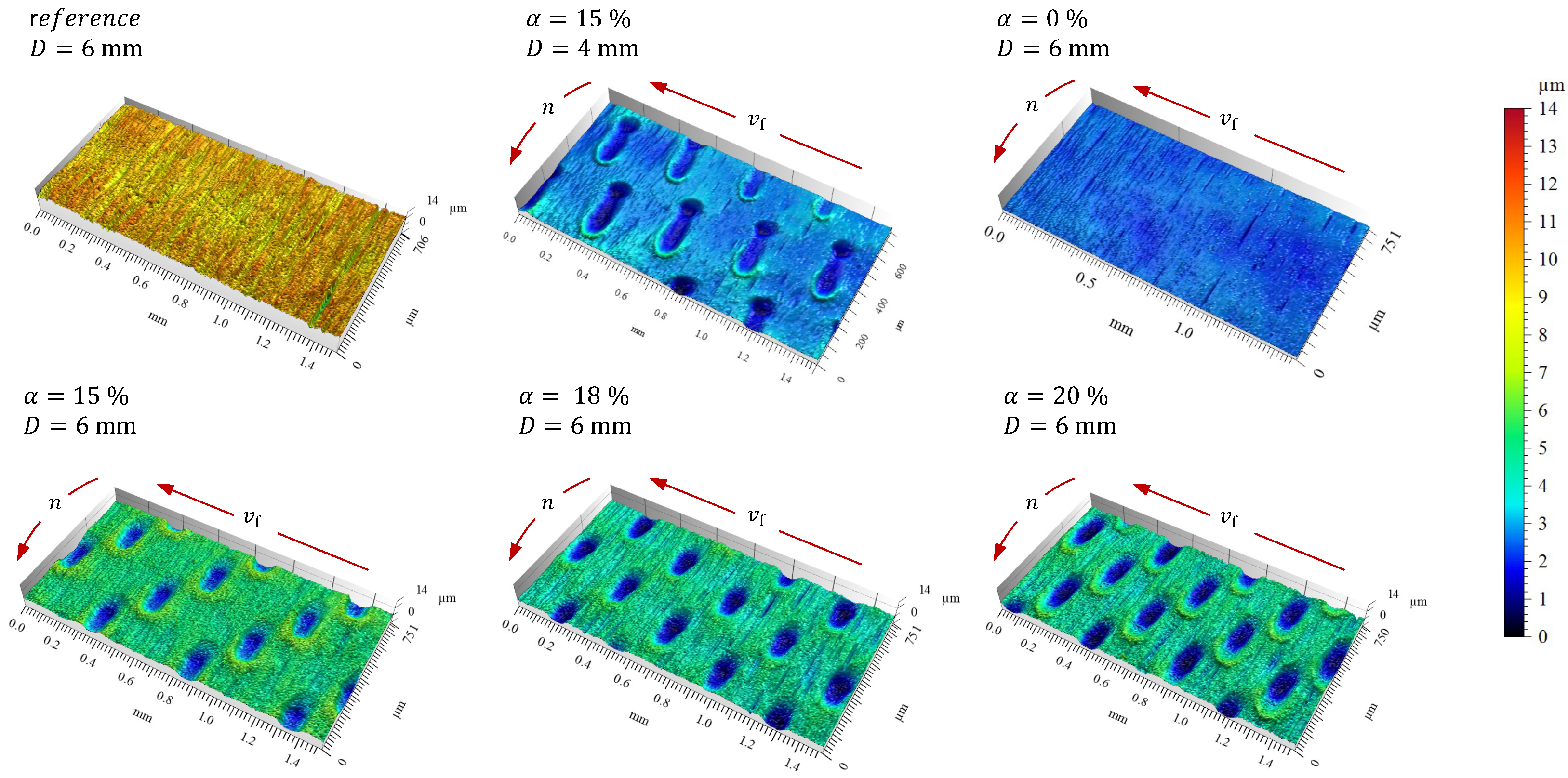
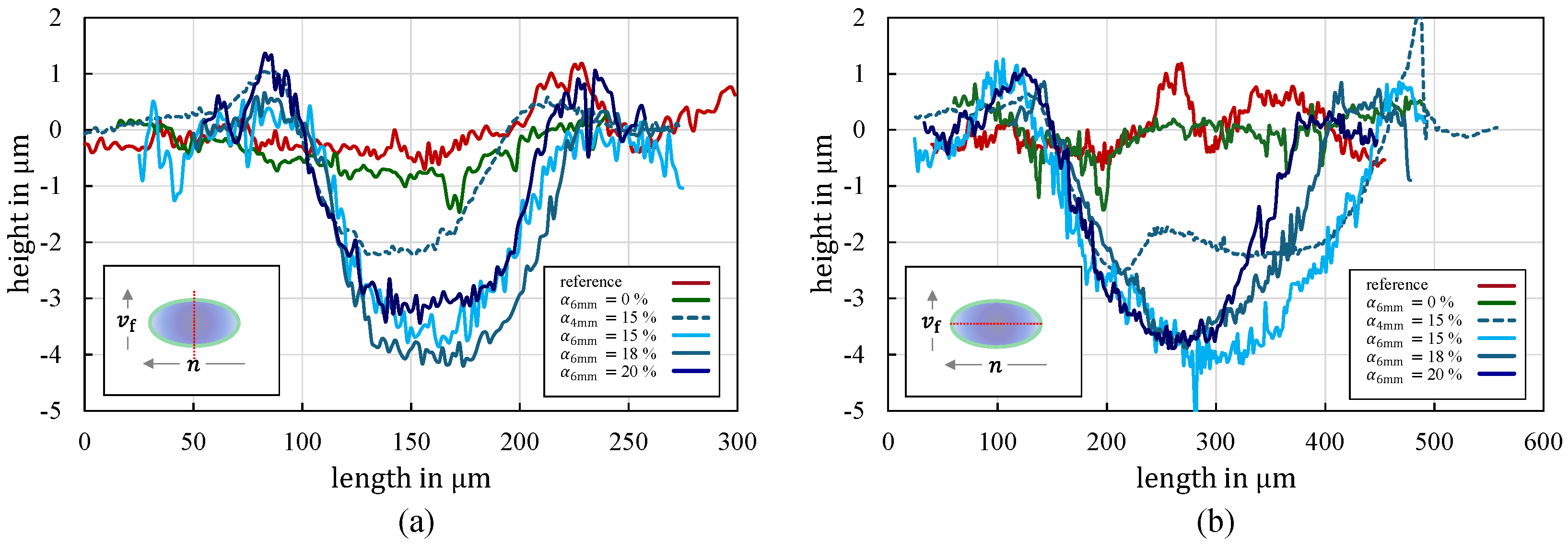
4.1. Textured Punch Surfaces

The topographies obtained by processing are shown in Figure 5. It is visible that the distribution of the cavities on the surface is strictly deterministic due to the precise control of the trajectory of the microtip by the developed texturing cell. The desired goal of increased repeatability and reproducibility through automated texturing has thus been achieved as expected. Compared with the manual handling of the rotation axis in the previous work [31], the processing time was also significantly reduced from around 50 min to an average of 2 min per textured lateral surface. However, the superposition of the rotation around the punch axis due to the rotational speed n and the contact time of the microtip due to the peening frequency f i result in elliptical cavities.
Figure 6 shows an intersection of both symmetry axes of the resulting intersected cavities in the direction of feed and rotation. The shape of the cavities in the direction of v f is very similar for the 6 mm punches. The average cavity depth for a targeted texturing of 20% is 3 µm, and for 18% and 15% it is 3.8 µm. The cavity width for all coverage ratios is 120 µm. Larger differences occur when the direction of rotation is analyzed. As the coverage ratio increases, the cavity length decreases from 340 µm for α = 15 % , to 270 µm for α = 20 % , resulting in an average aspect ratio of A ¯ R = 0.023 ± 0.014 . The effect of ellipse formation is proportional to the surface speed, as can be seen when comparing Figure 6 and Table 1. The relative speed at the surface v t rises with increasing rotational speed n for a constant punch diameter (Figure 3b). Due to a constant peening frequency f i , the contact time of the microtip with the surface and the cavities produced is shorter. This also explains the almost identical cavity lengths of the punches, with D = 4 mm and D = 6 mm for α = 15 % . The lower penetration depth for the blanking punch with a diameter of 4 mm is due to the greater curvature of the surface. As a result of the elliptical cavities, the predicted coverage ratio differs from the achieved coverage ratio.
Table 3 shows the coverage ratios α t r u e achieved and the associated roughness parameters of the textured surface areas. The reduced valley depth R v k value increases with increasing coverage ratio. As the number of cavities increases, more potential lubricant pockets and wear particle reservoirs are generated, which can potentially benefit the process. As a consequence, the S z value, which is the sum of the largest peak heights per area, also increases, resulting in artificially roughened surfaces due to the surface modification. S z increases by 17.7% for the surface with the highest coverage ratio of α t r u e = 22.3 % , compared with the surface with the lowest coverage ratio of α t r u e = 16.1 % . Since MHP is a forming process and no material is removed, volume constancy applies. This also leads to the formation of an expanded material accumulation in the direction of rotation. Due to volume consistency, the material is simply displaced, and the arithmetic mean height S a as an integral over the entire surface area analyzed shows no clear tendency and varies by 0.82 ± 0.036 µm for a punch diameter of 6 mm.

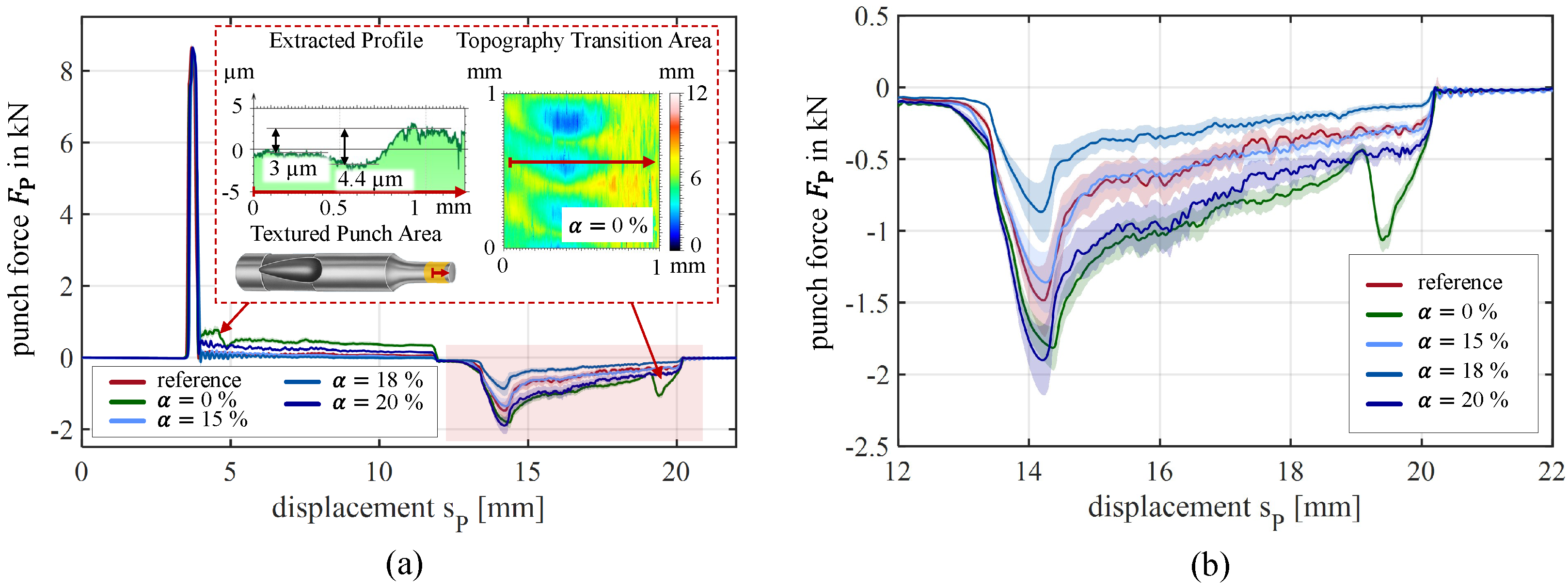
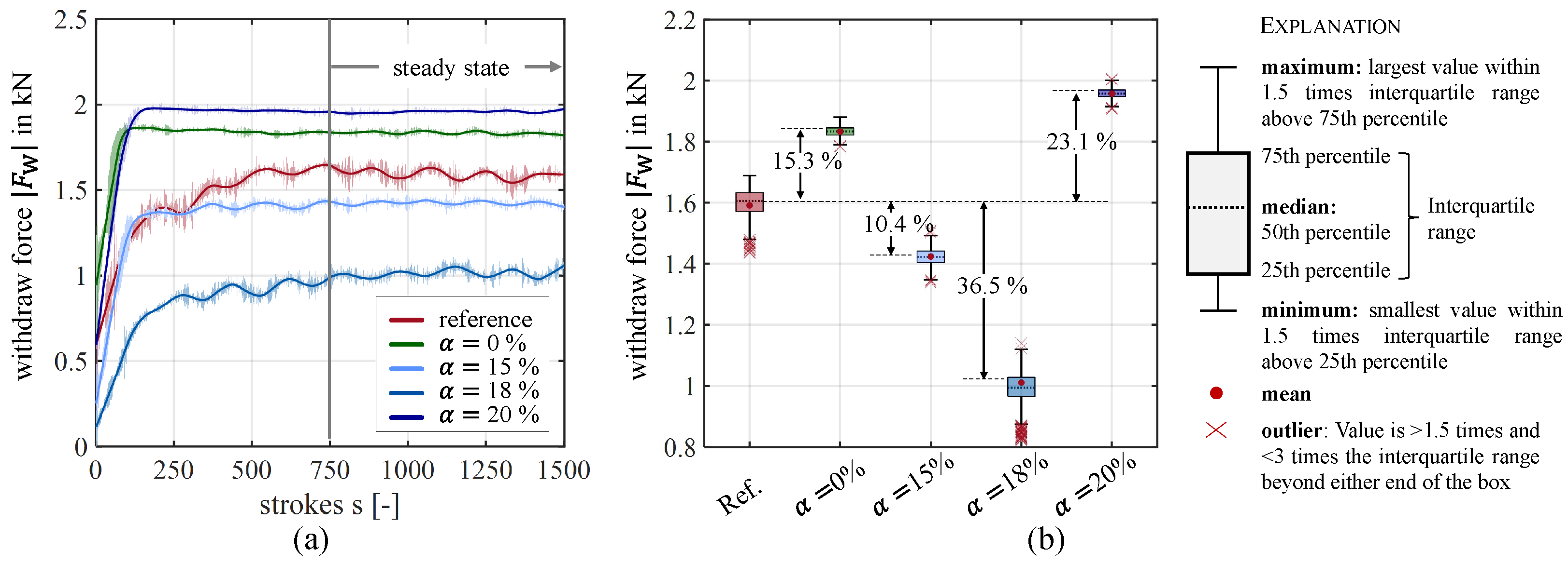
4.2. Process Performance

Figure 7 shows the experimental data of the blanking tests performed. The mean value of 1500 consecutive strokes was determined and is shown with the associated error band based on the standard deviation. The individual phases presented in Figure 4b can be clearly identified for each punch examined. The surface modification shows no significant influence on the punch phase. This is to be expected, since the modified surface is not yet in contact with the sheet metal during this phase of the blanking process. The effect on tribological performance becomes noticeable in the push phase and especially in the withdraw phase (Figure 7b).
A drop in force in the push phase and a reciprocal increase in force in the withdraw phase are noticeable for a punch that was machined using conventional MHP ( α = 0 % ). These anomalies can be localized to about 1 mm after penetrating the sheet, as well as leaving the die. This correlates with the selected machining distance to the edge radius (see Section 3.1). Conventional MHP modifies the entire surface textured and results in a significantly smoother surface than the initial state (see Figure 5). This results in a geometric transition from the initial to the smoothed surface (see Figure 4a). The geometric edge translates to a change in tribological load due to a narrower clearance by almost 6 µm for the untextured area and results in the inconsistency observed in the two phases. As the initial surface is only marginally modified by embossing the cavities due to texturing with a micro-tip, the anomalies are not observed for the textured punches. Previous studies have identified the withdraw phase as a particularly friction-sensitive phase due to a shift in clamping forces and sensitivity to lubrication [35]. Moghadam et al. confirmed a strong correlation between the lubricant pick-up and the resulting process performance in the withdraw phase [36]. This is also evident in the present study. The surface modification by texturing and plain MHP leads to a significant relative and absolute separation of the individual withdrawal forces (Figure 7b). For a detailed investigation of the tribological performance in the withdraw phase, Figure 8a shows the development of the minimum withdrawal force per stroke for the 1500 strokes performed. The graphs are the product of the smoothed data points. Absolute values are shaded. It is observed that the withdrawal forces of the punches initially increase and then converge to stationary behavior. This steady state is reached for all punches after approximately 750 strokes. The running-in phase is due to a thermal expansion of the blanking punch and the associated reduction in clearance. The punches with α = 0 % and α = 20 % reach the greatest values, which indicates that those surfaces have a higher coefficient of friction and therefore result in higher withdrawal forces. As a consequence, more energy is dissipated into heat. The punches expand faster and therefore reach stationary behavior faster. Based on the 750 strokes in stationary behavior the tribological performance is evaluated for the withdrawal forces of the punches examined. To that end, the variation in withdrawal force within the stationary behavior was ascertained. This fluctuation is visualized in the box plot in Figure 8b.
The most notable distribution of the measured values is observed for the reference and 18%, attributed to the apparent periodic fluctuation. The upper and lower percentiles are indicative of minimal fluctuation. The results obtained from this analysis permit a robust inference regarding the properties of the modification in the retraction phase. A relative analysis of the resulting mean values shows that texturing with α of 15% and 18% contributes to a reduction in the acting frictional forces in the withdraw phase compared with the untextured reference punch. In particular, this is significant for an α of 18% and a reduction of 36.5%. This is in good agreement with previous investigations by Schumann et al. on the tribological performance of textured surfaces observed in strip drawing tests. Textures with a coverage ratio of α = 24 % resulted in an increase of the COF by 26%, whereas lower coverage ratios resulted in a decrease in the COF when compared with the industrial standard [33]. Despite the thin lubrication layer, the improvement in the wetting properties and the transport of the lubricant in the critical areas of the tool–sheet contact through the cavities is a possible explanation. As demonstrated by Olson et al., lubricant is initially obtained from the work sheet [37], then sealed in the cavities during sheet penetration, and therefore transported into the forming zone. Similar findings were obtained by studies of Kitamura et al., where the lubricant traces were observed on the blank and the potential for minimum quantity lubrication for blanking was demonstrated [26]. An analogous sealing phenomenon is observed by Shimizu et al. for a deep drawing process using textured silica dies supporting the explanation [25]. The presence of homogeneously distributed lubricant cushions, in conjunction with the enabled minimum quantity lubrication, results in a reduced withdrawal force. The results show that a targeted design of the coverage ratio is of essential importance. Even a slight increase in α to 20% leads to an increase in the withdrawal force of 23.1%, resulting in a deterioration in the process properties and ultimately in wear behavior. This is consistent with the theory of Uehara et al. [34]. It is stated that two counteracting mechanisms influence the tribological performance regarding the degree of coverage ratio. As the coverage ratio increases, the number of cavities increases. This improves lubrication and reduces the COF. Simultaneously the real contact area decreases with increasing coverage, leading to increased contact normal stresses (CNS) for a constant external load [34]. Due to the lack of separation caused by the lower amount of lubricant in the starved lubrication condition, the second effect is more dominant. For the tribological loads under investigation, texturing with α = 20 % appears to have exceeded this threshold. The effect of the effective CNS predominates, and the embossed cavities resemble artificial roughness.

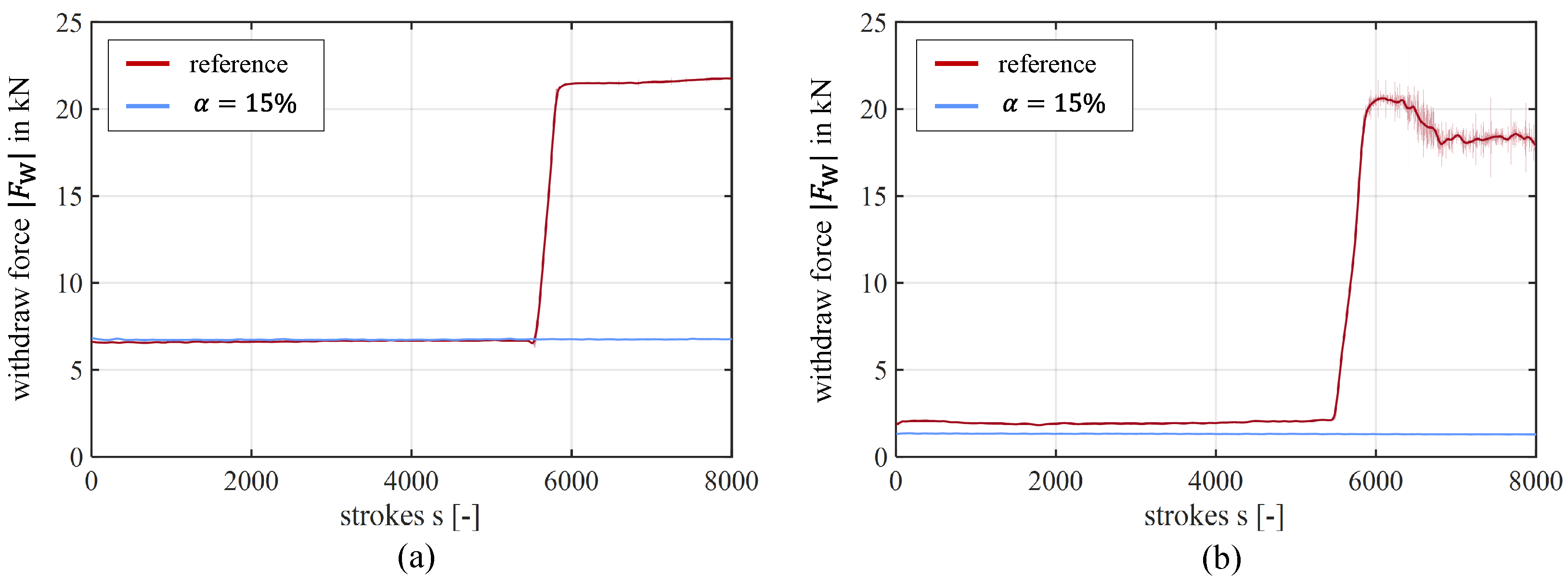
4.3. Wear Sensitive Blanking

Similar to the previous section, Figure 9 shows the development of the maximum punch force and the magnitude of withdrawal force over the strokes performed under the adapted conditions (Table 2). Figure 9a shows the rapid onset of wear of the reference punch from stroke 5500 based on the increase in punch force. Then, it stagnates from around stroke 5800. A similar picture emerges for the withdraw phase. A detailed analysis shows that the increase in force in the withdraw phase already begins at stroke 5492. Again, this shows the sensitive influence of the friction conditions in the withdraw phase on the overall process [35]. The observation suggests that wear initially develops during the withdraw phase in the form of galling and results in increased friction at low relative speeds. Within the next 10 strokes, progressive adhesive wear significantly reduces the effective clearance, resulting in a rapid increase in detectable forces. A comparison with the textured counterpunch does not show any versa-critical wear after 8000 strokes. The test series was terminated at this point (see Figure 9).
The theory of wear development is reinforced by Figure 10, which shows camera and confocal images of both punches taken at the end of the test series. The described adhesive wear in the form of a golden coating in the immersion area is clearly visible (Figure 10a). Adhesion of the lateral punch surface is a common phenomenon for this setup and is typically observed for higher immersion depths [31,38]. The extended immersion depth results in an extended frictional contact and higher relative speeds when penetrating and exiting the die due to the kinematics of the high-speed press. The enhanced thermal potential inherent in this setup contributes to an overall greater tendency for adhesion. In industrial applications, the depth of immersion is therefore maintained at a low level. For these setups, the primary observable phenomenon is typically abrasive wear of the edge radii [39,40,41]. Therefore, for the immersion depth selected in the study, it is expected that failure due to adhesion will outweigh failure due to abrasion when testing sheets with sufficient reactivity. However, additional materials need to be tested to make a definitive statement. In the present study, the adhesion layer develops insidiously during the process but gradually leads to a reduction in the effective clearance. A constant increase can be observed in the force curve of the withdraw phase beginning at 3000 strokes, which further indicates this correlation (Figure 10b). Kubik et al. observed the presence and development of adhesion layers on the lateral surface of blanking punches when investigating high-strength steel. Their findings indicate that the withdraw phase significantly correlates with the formation of adhesion. This formation does not affect the push phase [38]. CNS increases on the lateral surface, and the resulting increase in frictional force due to increasing tribologic loads leads to increased heat dissipation, which further raises the tendency for adhesive wear on the punch. Welm et al. observed that the amount of adhesive wear is increased by a superposition of frictional heating and temperature increase based on dissipating plastic work [42]. In sections of high surface pressure, passivation layers of the tool steel are broken up [43]. Consequently, clean and therefore highly reactive metallic ions come into contact [44]. The chemical reactivity is increased, and the potential for adhesion is enhanced, ultimately leading to cold welding [45]. Because of the separation of the adhesive contact area due to the process dynamic, the cold welding on the harder friction partner leads to the typical and characteristic wear appearance [46]. The effects listed above reinforce each other until the resulting gap narrows to a certain size, the process is no longer controllable, and the tool ultimately fails. This finding aligns with the hypothesis proposed by Lind et al., who suggested that the wear mechanism during a blanking process can be categorized into three distinct phases, with abrasive wear, adhesive wear, and the growth of friction junctions, respectively, being the predominant factors [47]. This is confirmed by the tarnish on the punch shaft, the microscope images of the reference punch after 8000 strokes, and the microscope images of the 30 µm thick adhesion layer in the immersion area.
The surface of the textured blanking punch is in significantly better condition despite 3000 additional load cycles. Only a slight golden shimmer can be seen in the immersive area of the punch shaft. Heat tarnishing is not observed. This impression is confirmed when looking at the corresponding topographies under a confocal microscope. Although the texturing shows slight deposits at the edge of the cavities in the form of adhesion, it is still clearly recognizable and continues to fulfill its wear-reducing function. To further investigate the phenomena, an SEM image and EDX mapping were performed (see Figure 11). In contrast to the findings of Shimizu et al. [25], no deposition of wear particles could be shown in the cavities (see Figure 11b,c). One potential explanation for this phenomenon is the absence of mechanical anchoring, as previously mentioned. Due to the different aspect ratios (AR) of the two works and the considerably disparate process speeds, divergent phenomena are observed. While particles can accumulate in the cavities at higher AR ( A R = 0.1 ), low relative velocities, and low process dynamics [25], this effect is less pronounced at lower AR, such as A ¯ R = 0.023 . This phenomenon is further compounded by the low lubricant quantity and high CNS, which makes it more susceptible to the occurrence of MicroPlasto Hydrodynamic Lubrication (MPHDL) [48]. Shimizu et al. utilized the effect to improve lubricant performance through different cavity designs [49]. This mechanism can occur due to a combination of static and dynamic pressure build-up in the thin lubricant film at the converging gap between the two bodies [50]. The sealed cavities can supply fluid lubrication to surrounding areas, where the boundary film has previously been destroyed, resulting in reduced friction [8]. The mappings clearly show that copper and zinc are only attached outside the textures on the initial punch surface due to the brass sheet used. It is assumed that the embossed cavities transport fine abrasive particles from the tribologically active forming zone. Kubik et al. demonstrated the correlation of chipping and adhesion, contributing to an increased number of particles that could potentially lead to grooves [38]. Due to the relatively shallow depth of the cavities compared with their flat spread combined with constant changes in the direction of the blanking punch during the process, there is no mechanical anchoring of the particles in the cavities. These are sealed by the interface with the sheet metal, which is analogous to the sealed condition of the residual lubricant. This results in the prevention of rolling over the surface by contact with the sheet metal, leading to microgrooves [51]. Without surface modification, the abrasive particles contribute to the formation of microgrooves. This microcutting and -forming process is observed by Kayaba et al. [52]. At these points, local stress peaks will eventually occur during the process, leading to adhesive wear. This phenomenon is described as ’three-body abrasive wear’, and it is only able to occur in circumstances where particles are unconstrained and have the capacity to slide or to roll on a surface [53]. These microgrooves serve as nucleation centers for adhesion [54]. The textured punch was thus able to inhibit the progressive development of wear and prevent the onset of significant adhesive wear.

5. Conclusions

The findings of the tribometer studies on the texturing of tool surfaces by MHP [33] have been successfully transferred to rotationally symmetrical blanking punches. To this end, a texturing machining center was put into operation, and equations for targeted deterministic texturing were derived. The modified punch surfaces were examined in the blanking process, and the friction- and wear-improving properties were demonstrated. Where adhesive wear is the dominant wear phenomenon, maintenance intervals can be significantly extended by texturing. This increases the overall productivity of industrial processes while still maintaining the required product quality. The key findings of this work can be summarized as follows:
  • The lowest possible speeds should be set to reduce material accumulation and the formation of elongated cavities.
  • The texturing of the lateral surface with a coverage ratio of 18% contributed to a reduction in the required withdrawal force of 36.6%.
  • This allows the amount of lubricant required to be reduced while maintaining the tribological system, offering the potential for minimum quantity lubrication.
  • It has been shown that microtexturing using MHP can also inhibit progressive adhesive wear.
Future work will focus on the numerically supported design of individual cavities. These are to be dimensioned specifically for certain load collectives. In addition, the methodology presented will be used to utilize surface modification by MHP for other forming processes, further investigate the reduced lubricant requirement using different lubricant quantities, and investigate the observed effects and phenomena for further material combinations.

Author Contributions

Conceptualization, P.S. and P.G.; methodology, P.S.; software, V.A. and P.S.; investigation, P.S.; resources, P.S. and P.G.; writing—original draft preparation, P.S.; writing—review and editing, P.S. and P.G.; visualization, P.S.; supervision, P.G.; project administration, P.S. and P.G.; All authors have read and agreed to the published version of the manuscript.

Funding

The research was funded by the program for “Industrial Research” (IGF) of the Federal Ministry of Economic Affairs and Climate Action (BMWK) and the German Federation of Industrial Research Associations (AiF).

Institutional Review Board Statement

Not applicable.

Informed Consent Statement

Not applicable.

Data Availability Statement

The data that support the findings of this study are available from the corresponding author, P.S., upon reasonable request.

Acknowledgments

The presented results are part of the research projects “Tribological optimization of blanking punches through microtexturing by machine hammer peening” (21560 N) of the European Research Association for Sheet Metal Working (EFB) and “Smart Wear-Holistic approach to control, prevent and predict wear phenomena in high-speed blanking based on hybrid surface technologies and sensory inline information” (5031605KP1) of the German Federation of Industrial Research Associations (AiF-ZIM), both funded by the Federal Ministry for Economic Affairs and Climate Action (BMWK). Furthermore, the authors would like to thank Bruderer AG for providing the high-speed press BSTA 810-145 on which the punching experiments were carried out. The authors would also like to thank the Department of Physical Metallurgy (PhM) for their assistance in providing the SEM-EDX images.

Conflicts of Interest

The authors declare no conflicts of interest.

Abbreviations

The following abbreviations are used in this manuscript:
ARAspect Ratio
COFCoefficient of Friction
CNSContact Normal Stress
CVDChemical Vapor Desposition
EDXEnergy-dispersive X-Ray Spectrometer
MHPMachine Hammer Peening
MPHDLMicroPlastic Hydro Dynamic Lubrication
PVDPhysical Vapor Desposition
REACHRegistration, Evaluation, Authorization, and Restriction of Chemicals

References

  1. Schmidt, R.; Zimmermann, A.; Möhring, M.; Nurcan, S.; Keller, B.; Bär, F. Digitization-perspectives for conceptualization. In Advances in Service-Oriented and Cloud Computing, Proceedings of the Workshops of ESOCC 2015, Taormina, Italy, 15–17 September 2015; Revised Selected Papers 4; Springer International Publishing: Berlin/Heidelberg, Germany, 2016; pp. 263–275. [Google Scholar]
  2. Sandberg, J.; Holmström, J.; Lyytinen, K. Digitization and phase transitions in platform organizing logics: Evidence from the process automation industry. Manag. Inf. Syst. Q. 2020, 44, 129–153. [Google Scholar] [CrossRef]
  3. Bilgin, B.; Magne, P.; Malysz, P.; Yang, Y.; Pantelic, V.; Preindl, M.; Korobkine, A.; Jiang, W.; Lawford, M.; Emadi, A. Making the case for electrified transportation. IEEE Trans. Transp. Electrif. 2015, 1, 4–17. [Google Scholar] [CrossRef]
  4. Huang, C.; Romero, J.; Osterman, M.; Das, D.; Pecht, M. Life cycle trends of electronic materials, processes and components. Microelectron. Reliab. 2019, 99, 262–276. [Google Scholar] [CrossRef]
  5. Trzepieciński, T. Recent developments and trends in sheet metal forming. Metals 2020, 10, 779. [Google Scholar] [CrossRef]
  6. Klose, S.; Pauliuk, S. Sector-level estimates for global future copper demand and the potential for resource efficiency. Resour. Conserv. Recycl. 2023, 193, 106941. [Google Scholar] [CrossRef]
  7. Ahmadi, M.; Amouzegar, Z.; Khalili, S.; Asadi, S.; Aghajani, S.; Aryanrad, P.; Afkhami, A.; Madrakian, T.; Thomas, S.; Nguyen, T. Miniaturization—An introduction to miniaturized analytical devices. In Micro-and Nanotechnology Enabled Applications for Portable Miniaturized Analytical Systems; Elsevier: Amsterdam, The Netherlands, 2022; pp. 3–16. [Google Scholar]
  8. Arinbjarnar, Ú.; Schumann, P.; Moske, J.; Breunig, A.; Groche, P.; Nielsen, C. A review of methods and effects for improving production robustness in industrial micro-deep drawing. Int. J. Mater. Form. 2024, 17, 31. [Google Scholar] [CrossRef]
  9. Subramonian, S.; Altan, T.; Campbell, C.; Ciocirlan, B. Determination of forces in high speed blanking using FEM and experiments. J. Mater. Process. Technol. 2013, 213, 2184–2190. [Google Scholar] [CrossRef]
  10. Falconnet, E.; Chambert, J.; Makich, H.; Monteil, G. Prediction of abrasive punch wear in copper alloy thin sheet blanking. Wear 2015, 338, 144–154. [Google Scholar] [CrossRef]
  11. Sigvant, M.; Pilthammar, J.; Hol, J.; Wiebenga, J.; Chezan, T.; Carleer, B.; Boogaard, T. Friction in sheet metal forming: Influence of surface roughness and strain rate on sheet metal forming simulation results. Procedia Manuf. 2019, 29, 512–519. [Google Scholar] [CrossRef]
  12. Bay, N.; Ceron, E. Off-line testing of tribo-systems for sheet metal forming production. Adv. Mater. Res. 2014, 966, 3–20. [Google Scholar] [CrossRef]
  13. Colglazier, W. Sustainable development agenda: 2030. Science 2015, 349, 1048–1050. [Google Scholar] [CrossRef] [PubMed]
  14. Olson, D.D.; Bay, N.; Andreasen, J. Lubricant test for punching and blanking. In Proceedings of the 7th International Conference on the Technology of Plasticity, Yokohama, Japan, 27 October–1 November 2002; Volume 1, pp. 757–762. [Google Scholar]
  15. Arinbjarnar, Ú.; Moghadam, M.; Nielsen, C. Performance of inert particles as lubricant additives compared to fully formulated industrial forming oils in sheet metal forming. Discov. Mech. Eng. 2024, 3, 6. [Google Scholar] [CrossRef]
  16. Ibrahim, M.; Sulaiman, M. Assessment of lubricant performance enhanced with nanoadditive in punching and blanking of aluminium. J. Tribol. 2024, 43, 169–184. [Google Scholar]
  17. Bowman, D.; Van Calster, G. Reflecting on REACH: Global implications of the European Union’s chemicals regulation. Nanotech. L. Bus. 2007, 4, 375. [Google Scholar]
  18. Totre, A.; Nishad, R.; Bodke, S. An overview of factors affecting in blanking processes. Int. J. Emerg. Technol. Adv. Eng. (IJETAE) 2013, 3, 390–395. [Google Scholar]
  19. Podgornik, B.; Zajec, B.; Bay, N.; Vižintin, J. Application of hard coatings for blanking and piercing tools. Wear 2011, 270, 850–856. [Google Scholar] [CrossRef]
  20. Aravind, U.; Chakkingal, U.; Venugopal, P. A review of fine blanking: Influence of die design and process parameters on edge quality. J. Mater. Eng. Perform. 2021, 30, 1–32. [Google Scholar] [CrossRef]
  21. Bouzakis, K.; Michailidis, N.; Skordaris, G.; Kombogiannis, S.; Hadjiyiannis, S.; Efstathiou, K.; Erkens, G.; Rambadt, S.; Wirth, I. Effect of the cutting edge radius and its manufacturing procedure, on the milling performance of PVD coated cemented carbide inserts. CIRP Ann. 2002, 51, 61–64. [Google Scholar] [CrossRef]
  22. Patel, D.; Jain, V.; Ramkumar, J. Micro texturing on metallic surfaces: State of the art. Proc. Inst. Mech. Eng. Part B J. Eng. Manuf. 2018, 232, 941–964. [Google Scholar] [CrossRef]
  23. Velázquez-Corral, E.; Jerez-Mesa, R.; Llumà, J.; Wagner, V.; Dessein, G.; Travieso-Rodriguez, J. Wear resistance enhancement of AISI 1045 steel by vibration assisted ball burnishing process. Procedia CIRP 2016, 108, 287–292. [Google Scholar] [CrossRef]
  24. Saeidi, F.; Parlinska-Wojtan, M.; Hoffmann, P.; Wasmer, K. Effects of laser surface texturing on the wear and failure mechanism of grey cast iron reciprocating against steel under starved lubrication conditions. Wear 2017, 386, 29–38. [Google Scholar] [CrossRef]
  25. Shimizu, T.; Kobayashi, H.; Vorholt, J.; Yang, M. Lubrication analysis of micro-dimple textured die surface by direct observation of contact interface in sheet metal forming. Metals 2019, 9, 917. [Google Scholar] [CrossRef]
  26. Kitamura, K.; Makino, T.; Nawa, M.; Miyata, S. Tribological effects of punch with micro-dimples in blanking under high hydrostatic pressure. CIRP Ann. 2016, 65, 249–252. [Google Scholar] [CrossRef]
  27. Lechner, C.; Bleicher, F.; Habersohn, C.; Bauer, C.; Goessinger, S. The use of machine hammer peening technology for smoothening and structuring of surfaces. In Proceedings of the Annals of DAAAM for 2012 & Proceeding of the 23rd International DAAAM Symposium, Zadar, Croatia,, 24–27 October 2012; Volume 23, pp. 331–337. [Google Scholar]
  28. Hönnige, J.; Colegrove, P.; Williams, S. Improvement of microstructure and mechanical properties in wire+ arc additively manufactured Ti-6Al-4V with machine hammer peening. Procedia Eng. 2017, 216, 8–17. [Google Scholar] [CrossRef]
  29. Adjassoho, B.; Kozeschnik, E.; Lechner, C.; Bleicher, F.; Goessinger, S.; Bauer, C. Induction of residual stresses and increase of surface hardness by machine hammer peening technology. Ann. DAAAM 2012, 23, 697–702. [Google Scholar]
  30. Steitz, M.; Stein, P.; Groche, P. Influence of hammer-peened surface textures on friction behavior. Tribol. Lett. 2015, 58, 1–8. [Google Scholar] [CrossRef]
  31. Sticht, P.; Hohmann, J.; Groche, P. Effects of machine hammer peened surface textures on the tribological behavior of stamping tools. In Advanced Surface Enhancement, Proceedings of the 1st International Conference on Advanced Surface Enhancement (INCASE 2019)—Research Towards Industrialisation; Springer: Singapore, 2020; pp. 108–120. [Google Scholar]
  32. Schumann, P. Improved Process Efficiency with Microtextured Blanking Punches Using MHP. In Proceedings of the 10th International Conference on Tribology in Manufacturing Processes, Alcoy, Spain, 26–28 June 2024; Volume 3, p. 32. [Google Scholar]
  33. Schumann, P.; Groche, P.; Lindner, R. Influence of different deterministic surface texturing processes on friction and tool life for load collectives in sheet metal forming. In Proceedings of the Tribology International Conference, Lisbon, Portugal, 26–28 April 2023. [Google Scholar]
  34. Uehara, Y.; Wakuda, M.; Yamauchi, Y.; Kanzaki, S.; Sakaguchi, S. Tribological properties of dimpled silicon nitride under oil lubrication. J. Eur. Ceram. Soc. 2004, 24, 369–373. [Google Scholar] [CrossRef]
  35. Schumann, P.; Martin, D.; Kubik, C.; Schneider, T.; Groche, P. Analysis and evaluation of the clamping force on the tool surface during the blanking process. In NUMISHEET 2022, Proceedings of the 12th International Conference and Workshop on Numerical Simulation of 3D Sheet Metal Forming Processes, Toronto, ON, USA, 10–14 July 2022; Springer International Publishing: Cham, Switzerland, 2022; pp. 655–670. [Google Scholar]
  36. Moghadam, M.; Villa, M.; Moreau, P.; Dubois, A.; Dubar, L.; Nielsen, C.; Bay, N. Analysis of lubricant performance in punching and blanking. Tribol. Int. 2020, 141, 105949. [Google Scholar] [CrossRef]
  37. Olsson, D.; Bay, N.; Andreasen, J. Analysis of pick-up development in punching. CIRP Ann. 2002, 51, 185–190. [Google Scholar] [CrossRef]
  38. Kubik, C.; Groche, P. Force-based inline detection of wear evolution during blanking of cold rolled steels. Prod. Eng. 2024, 18, 709–720. [Google Scholar] [CrossRef]
  39. Hambli, R. Blanking tool wear modeling using the finite element method. Int. J. Mach. Tools Manuf. 2001, 41, 1815–1829. [Google Scholar] [CrossRef]
  40. Zheng, Q.; Zhuang, X.; Zhao, Z. State-of-the-art and future challenge in fine-blanking technology. Prod. Eng. 2019, 13, 61–70. [Google Scholar] [CrossRef]
  41. Falconnet, E.; Makich, H.; Chambert, J.; Monteil, G.; Picart, P. Numerical and experimental analyses of punch wear in the blanking of copper alloy thin sheet. Wear 2012, 296, 598–606. [Google Scholar] [CrossRef]
  42. Welm, M.; Tröber, P.; Weiss, H.; Demmel, P.; Golle, R.; Volk, W. Thermoelectrically based approaches to reduce adhesive wear during blanking. JOM 2020, 72, 2525–2535. [Google Scholar] [CrossRef]
  43. Buckley, D.; Johnson, R. The influence of crystal structure and some properties of hexagonal metals on friction and adhesion. Wear 1968, 11, 405–419. [Google Scholar] [CrossRef]
  44. Bowden, F.; Rowe, G. The adhesion of clean metals. Proc. R. Soc. London. Ser. A Math. Phys. Sci. 1956, 233, 429–442. [Google Scholar]
  45. Tabor, D. Interaction between surfaces: Adhesion and friction. Surf. Phys. Mater. 1974, 11, 475–529. [Google Scholar]
  46. Bay, N. Mechanisms producing metallic bonds in cold welding. Weld. J. 1983, 62, 137. [Google Scholar]
  47. Lind, L.; Peetsalu, P.; Põdra, P.; Adoberg, E.; Veinthal, R.; Kulu, P. Description of punch wear mechanism during fine blanking process. In Proceedings of the 7th International Conference DAAAM Baltic Industrial Engineering, Tallinn, Estonia, 22–24 April 2010; pp. 504–509. [Google Scholar]
  48. Mizuno, T.; Okamoto, M. Effects of lubricant viscosity at pressure and sliding velocity on lubricating conditions in the compression-friction test on sheet metals. J. Lubr. Technol. 1982, 104, 53–59. [Google Scholar] [CrossRef]
  49. Shimizu, I.; Martins, P.; Bay, N.; Andreasen, J.; Bech, J. Influences of lubricant pocket geometry and working conditions upon micro-lubrication mechanisms in upsetting and strip drawing. Int. J. Surf. Sci. Eng. 2010, 4, 42–54. [Google Scholar] [CrossRef]
  50. Bech, J.; Bay, N.; Eriksen, M. A study of mechanisms of liquid lubrication in metal forming. CIRP Ann. 1998, 47, 221–226. [Google Scholar] [CrossRef]
  51. Kato, K. Micro-mechanisms of wear—Wear modes. Wear 1992, 153, 277–295. [Google Scholar] [CrossRef]
  52. Kayaba, T.; Kato, K. The adhesive transfer of the slip-tongue and the wedge. Asle Trans. 1981, 24, 164–174. [Google Scholar] [CrossRef]
  53. Trezona, R.; Allsopp, D.; Hutchings, I. Transitions between two-body and three-body abrasive wear: Influence of test conditions in the microscale abrasive wear test. Wear 1999, 225, 205–214. [Google Scholar] [CrossRef]
  54. Groche, P.; Resch, F. Dry forming of aluminum alloys–Wear mechanisms and influencing factors. Mater. Werkst. 2015, 46, 813–828. [Google Scholar]
Figure 1. Schematical overview of the methodological approach based on [33].
Coatings 15 00136 g001
Figure 2. (a) Texturing cell; (b) texturing procedure and control parameters; (c) microtip of the peening head.
Coatings 15 00136 g002
Figure 3. (a) Geometric and (b) kinematic dependencies within the texturing cell; (c) coverage ratio.
Coatings 15 00136 g003
Figure 4. (a) Sensorial equipped blanking tool for measuring force signals; (b) blanking phases with corresponding force–displacement curve.
Coatings 15 00136 g004
Figure 5. Textured punch surfaces of blanking punches with different diameters and coverage.
Coatings 15 00136 g005
Figure 6. Intersected cavities of the textured blanking punches in (a) feed direction v f and (b) direction of rotation n.
Coatings 15 00136 g006
Figure 7. (a) Mean punch forces and (b) withdraw phase with correlating error bands of the investigated punches.
Coatings 15 00136 g007
Figure 8. (a) Withdrawal force per stroke of the investigated punches and (b) boxchart for the steady state.
Coatings 15 00136 g008
Figure 9. (a) Maximum punch force and (b) withdrawal force per stroke for the wear-sensitive setup.
Coatings 15 00136 g009
Figure 10. Camera and confocal images of the (a) reference and (b) textured punch at the end of the test series.
Coatings 15 00136 g010
Figure 11. (a) SEM image and associated EDX mapping of (b) Cu and (c) Zn, as well as (d) overall element distribution of the textured punch.
Coatings 15 00136 g011
Table 1. Texturing parameters.
α a i D v f n P i f i
in%in mmin mmin mm/minin 1/minin%in Hz
00.356620.1656.644050
150.356430.2384.94
150.356620.1656.64
180.330617.3052.44
200.308615.1249.05
Table 2. Material and process parameters used for blanking.
Material R m sD s R d i N (strokes)
in MPain mmin mmin 1/minin mm
CuZn30 510 ± 50 0.463007.41500
46009until failure
Table 3. Resulting coverage ratios and roughness parameters of the textured punches.
α α true Rvk Sz Sa
in%in%in µm in µmin µm
154mm18.21.7614.70.68
156mm16.11.7512.90.78
186mm18.41.8923.00.85
206mm22.32.0625.40.83
Disclaimer/Publisher’s Note: The statements, opinions and data contained in all publications are solely those of the individual author(s) and contributor(s) and not of MDPI and/or the editor(s). MDPI and/or the editor(s) disclaim responsibility for any injury to people or property resulting from any ideas, methods, instructions or products referred to in the content.

