Article

Study on Acoustic and Mechanical Properties of AlSi7Mg/TPU Porous Interpenetrating Phase Composites

1
Department of Mechanical and Electrical Engineering, Yangjiang Polytechnic, Yangjiang 529566, China
2
School of Mechanical and Energy Engineering, Guangdong Ocean University, Yangjiang 529500, China
*
Author to whom correspondence should be addressed.
Coatings 2025, 15(12), 1388; https://doi.org/10.3390/coatings15121388
Submission received: 27 October 2025 / Revised: 18 November 2025 / Accepted: 19 November 2025 / Published: 27 November 2025

Abstract

The rapid development of high-end equipment has created stringent requirements for multifunctional integration in materials. However, traditional porous materials have faced a fundamental trade-off between lightweight characteristics and mechanical and acoustic performance. To address this challenge, a design and fabrication method for interpenetrating phase composites (IPCs) based on triply periodic minimal surface (TPMS) structures was proposed. The effects of porosity, unit cell size, and structural type on the performance of porous structures were systematically investigated. TPMS frameworks were fabricated from AlSi7Mg alloy using laser powder bed fusion (LPBF). These frameworks were then combined with thermoplastic polyurethane (TPU) via a foaming infiltration process to create the AlSi7Mg/TPU IPCs. Acoustic and compression tests were performed using an impedance tube and a universal testing machine. The results indicated that, compared to unfilled TPMS structures, the IPCs exhibited a shift in the first peak acoustic absorption coefficient to lower frequencies, an increase (1.59 = fold) in the average acoustic absorption coefficient within the 500–6300 Hz range, and a significant enhancement (35.58 fold) in the average normal incidence transmission loss (TL). Under quasi-static compression, the plateau stage was sustained over 60% strain, and the energy absorption capacity increased by a factor of 3.56. This research provides a technical reference for developing multifunctional materials for aerospace and other acoustic applications.

1. Introduction

Porous structures are a key lightweight solution in the aerospace and transportation industries, as well as other engineering sectors. They are highly customizable and offer multifunctional integration potential. These materials have high specific strength and stiffness, as well as excellent acoustic absorption capabilities. These properties provide advantages in energy absorption [1,2], architectural acoustics [3], and thermal management [4,5,6]. In particular, the demand for lightweight, integrated acoustic and mechanical functionality in next-generation aircraft is driving the development of pore-topology co-design. The goal is to integrate load bearing, noise reduction, and thermal protection [7,8].
The field of porous structures has advanced to the point that these structures can be systematically categorized into three types. The three types are foam structures, honeycomb structures, and triply periodic minimal surfaces (TPMS), as shown in Figure 1. TPMS structures exhibit three advantages stemming from their mathematically defined, smooth surfaces with near-zero mean curvature. Three aspects have been identified as contributing to the material’s enhanced performance: first, the elimination of stress concentrations, which are commonly found in traditional lattices, results in improved mechanical fatigue resistance due to the continuity of curvature [1]; second, the enhancement of fluid mass transfer and acoustic dissipation efficiency due to the high specific surface area leads to an improvement in physical field regulation [9]; third, the ability to define porosity, specific surface area, and pore-size distribution with precision through parametric modeling results in fine-grained parametric control [10]. However, the spatial complexity of TPMS structures poses significant manufacturing challenges. Conventional machining cannot create interconnected internal pores; casting introduces pore defects; and material flow restrictions limit the use of forging. In recent years, laser powder bed fusion (LPBF) technology has become the preferred method for producing metallic TPMS structures due to its high precision, ability to fabricate complex geometries, and wide material compatibility.
LPBF has successfully fabricated TPMS structures from various materials, including titanium, titanium alloys, aluminum, aluminum alloys, and 316L stainless steel, as well as other alloys. However, aluminum alloy structures still face critical bottlenecks, including brittle fracture [11], unstable compressive stress–strain responses, and inadequate energy absorption [12]. To overcome these limitations, researchers have proposed interpenetrating phase composites (IPCs), in which synergistic multiphase interactions overcome the constraints of monolithic materials. Specifically, the study found that TPMS-based Al-Al2O3 IPCs increased the compressive offset yield stress by approximately 6% compared to pure aluminum [13]. Furthermore, the study established that Ti/Al IPCs achieved stabilized structural deformation under quasi-static axial compression while reducing peak loads [14]. Finally, this study demonstrated that Al-epoxy resin IPCs exhibited a 25-fold enhancement in energy absorption capacity [15]. These findings conclusively demonstrate that IPCs topology design successfully overcomes the intrinsic limitations of unitary materials, activates multifunctional TPMS capabilities, and enables broader applications in performance-critical fields.
Research on the acoustic performance of TPMS structures is still in its early stages, particularly with regard to broadband sound absorption and improved sound insulation. However, advancements in acoustic metamaterials have led to novel methodologies for enhancing TPMS structures. Gradient-porosity designs, specifically graded TPMS structures with a porosity ranging from 60.51% to 77.59%, have been shown to achieve broadband sound absorption across the 500–6300 Hz frequency range. In this range, their average 1/3-octave absorption coefficient substantially exceeds that of reverse-gradient configurations (60.51% to 77.59%), thereby validating the efficacy of porosity gradients in multiband dissipation performance [16]. Topological optimization has been shown to enable 2.4 cm-thick gyroid sandwich panels to achieve a transmission loss of more than 20 dB throughout the frequency range of 250–5000 Hz, thereby highlighting the synergistic effect of lightweighting and broadband noise attenuation [17]. LPBF-manufactured micro-perforated TPMS sandwich structures achieve peak absorption coefficients exceeding 0.8 above 3000 Hz, demonstrating the capability of additive manufacturing for targeted high-frequency acoustic control [18].
Thermoplastic polyurethane (TPU) foam is an efficient material for acoustic applications due to its low density, ease of processing, and exceptional acoustic absorption. However, its comparatively inferior mechanical characteristics limit its use in load-bearing engineering structures. To address this, researchers are exploring TPU-TPMS (IPCs), which enhance broadband acoustic absorption and mechanical performance synergistically. Infiltrating primitive minimal surface structures with soft TPU has been shown to produce IPCs with enhanced strength and toughness, diminished stress concentrations, and mitigated shear failure [19]. Aluminum/TPU IPCs have demonstrated high energy absorption capacity and impact resistance [20]. With increasing aluminum volume fraction, aluminum foam/polyurethane composites exhibit both higher compressive strength and modified failure mechanisms [21]. These findings yield critical insights for developing multifunctional structures that achieve both high mechanical performance and superior acoustic properties.
This study systematically assesses the multifunctional performance of these composite structures. It adopts a rigorous approach informed by recent advances in standardized characterization procedures. In particular, it uses the finite element framework for coating integrity in ceramic matrix composites [22]. The key performance metrics for acoustic evaluation are the sound absorption coefficient and transmission loss. Plateau stress and energy absorption capacity are used for structural assessment.
In this work, a novel methodology for fabricating AlSi7Mg/TPU interpenetrating phase composites is developed by integrating LPBF with TPU foaming. This research systematically investigates the effects of unit cell size, porosity, and structural topology on the acoustic and mechanical properties of the resulting IPCs. The primary objectives are to validate the following hypotheses: (1) increased porosity shifts the sound absorption peak toward lower frequencies; (2) gyroid topology exhibits superior broadband acoustic performance compared to Primitive and IWP structures at equivalent porosity; and (3) TPU infiltration significantly enhances the energy absorption capacity and toughness of the composite structure. The anticipated findings are expected to provide practical guidance for designing IPCs with tailored acoustic performance and mechanical resilience, thereby offering key design references for developing lightweight, dual-functional aerospace structures capable of simultaneous sound absorption and load-bearing capacity.

2. Materials and Methods

2.1. Design of TPMS

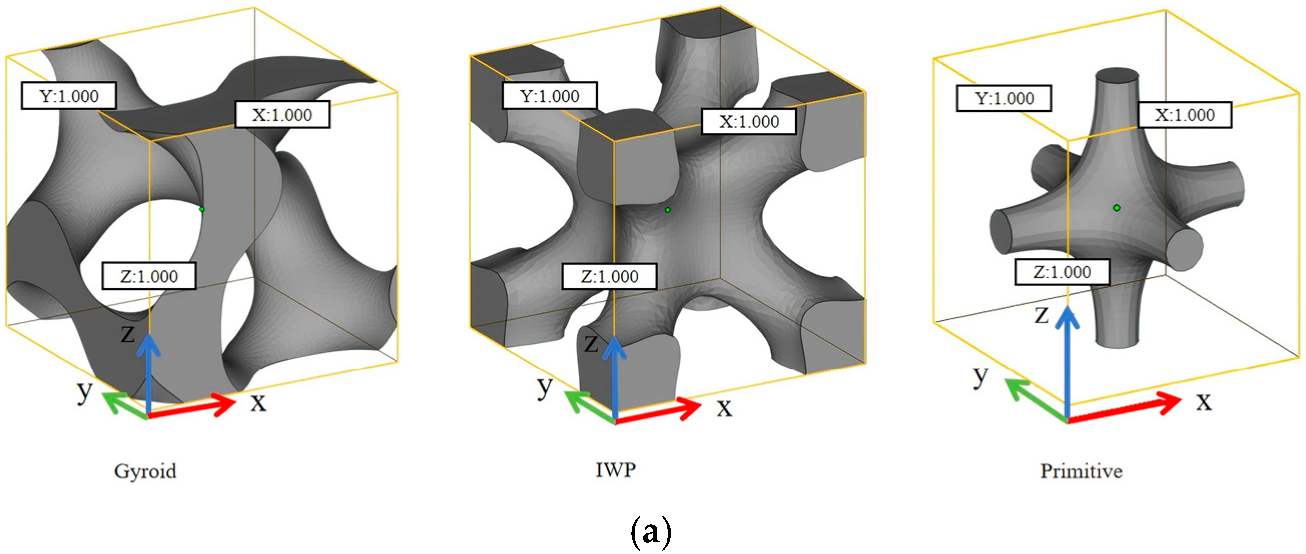
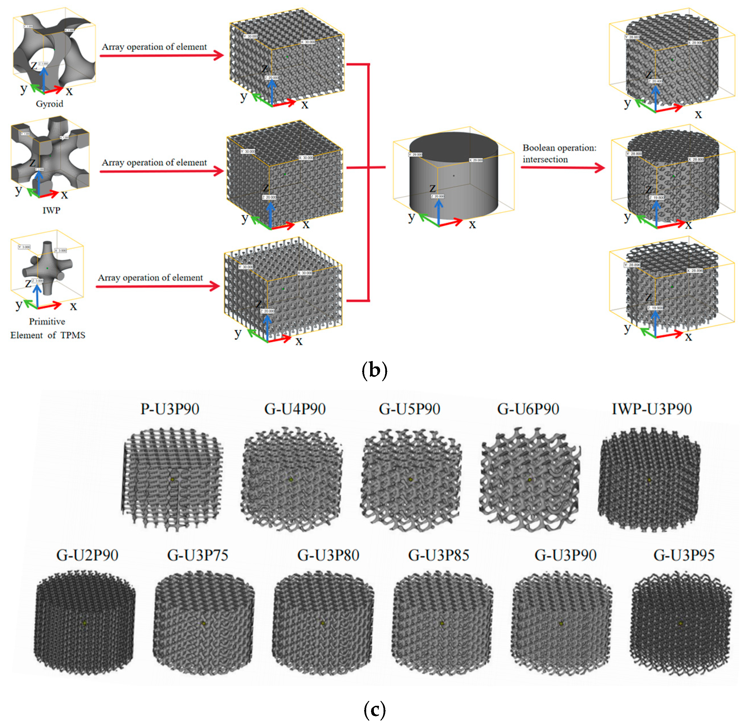
Based on the implicit functions defined in [23], the TPMS isosurfaces were generated within a finite computational domain. Specifically, the gyroid (G-surface), IWP-surface, and primitive (P-surface) were constructed by evaluating Equations (1)–(3) [24], respectively, using MATLAB (R2021b, The MathWorks Inc., Natick, MA, USA) [25]. The resulting isosurfaces underwent boundary closure to yield their corresponding minimal periodic unit cells. The parameter s in the implicit functions controls the dimensions of each minimal periodic unit cell. The fabrication process involved the periodic arrangement of unit cells to construct a bulk TPMS structure with dimensions of 30 × 30 × 20 mm3. Subsequently, a solid cylinder (29 mm in diameter, 20 mm in height) was subtracted from the structure under investigation by means of a Boolean operation. The process yielded a cylindrical model whose interior surface conforms precisely to the TPMS architecture. The characteristic cell size is proportional to parameter s, while the structural periodicity is governed by the computational domain extents (x, y, z). As schematically illustrated in Figure 2, the design process was executed in its entirety, culminating in the creation of the resultant model.
F g y r o i d = sin ( 2 π x / s ) × cos ( 2 π y / s ) + sin ( 2 π y / s ) × cos ( 2 π z / s ) + sin ( 2 π z / s ) × cos ( 2 π x / s ) C
F I W P = 10 ( cos ( 2 π x / s ) × cos ( 2 π y / s ) + cos ( 2 π y / s ) × cos ( 2 π z / s ) + cos ( 2 π z / s ) × cos ( 2 π x / s ) ) 5 ( cos ( 4 π x / s ) + cos ( 4 π y / s ) + cos ( 4 π z / s ) ) C
F p r i m i t i v e = cos ( 2 π x / s ) + cos ( 2 π y / s ) + cos ( 2 π z / s ) C
This study employs a systematic nomenclature for each specimen configuration that combines TPMS topology, minimal unit cell size, and porosity. The naming convention uses alphabetic codes to denote the TPMS architecture: ‘G’ for gyroid, ‘P’ for primitive, and ‘IWP’ for IWP. Following this code is the ‘U’ suffix and a single-digit numeral indicating the unit cell dimension in mm. The suffix ‘P’, followed by two digits, denotes the porosity percentage. A comprehensive overview of the parameter sets for the eleven fabricated TPMS structures is presented in Table 1. For example, ‘G-U2P90’ refers to a gyroid architecture with a unit cell size of 2 mm and 90% porosity.

2.2. Additive Manufacturing of TPMS

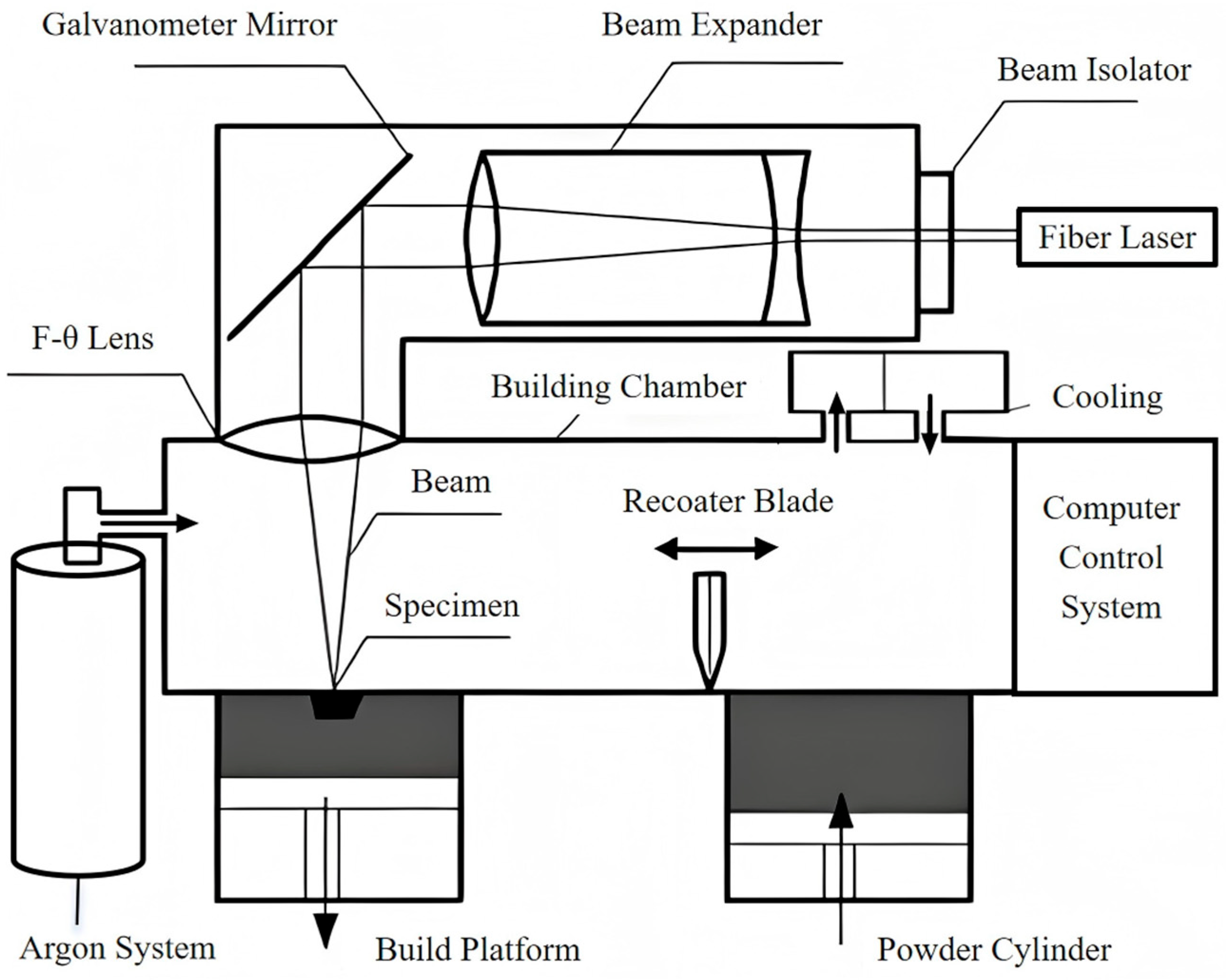
The TPMS structures were produced using laser powder bed fusion (LPBF) equipment, the Dimetal-280, supplied by Guangzhou Laseradd Additive Technology Co., Ltd., Guangzhou, China (as shown in Figure 3). Contour scanning was applied during the laser manufacturing process, with a spot compensation of 0.1 mm. The key processing parameters for LPBF were as follows: laser power of 150 W, scanning speed of 1300 mm/s, layer thickness of 0.03 mm, and scanning space of 0.09 mm [26].
A chessboard scanning strategy with 67° inter-layer rotation (5 × 5 mm2, 30% overlap) was adopted to control defects; Low-power scanning (150 W, 1300 mm/s) was used to maintain the powder bed temperature at 80–100 °C, and high-purity argon was applied to keep the oxygen content below 0.1%; Samples were built with pore channels parallel to the build direction, and powder size distribution and layer thickness were optimized to control surface quality.
The AlSi7Mg powder was supplied by Avimetal Powder Metallurgy Technology Co., Ltd., Beijing, China. Its particle size distribution ranged from 15 to 53 µm (D10 = 22.56 µm, D50 = 38.37 µm, D90 = 60.90 µm). It has a nominal composition (in wt.%) of Bal. Al, 6.730 Si, 0.678 Mg, 0.281 Fe, 0.198 Mn, 0.045 Cu, 0.012 Ni, and 0.070 O [27].

2.3. Fabrication of IPCs

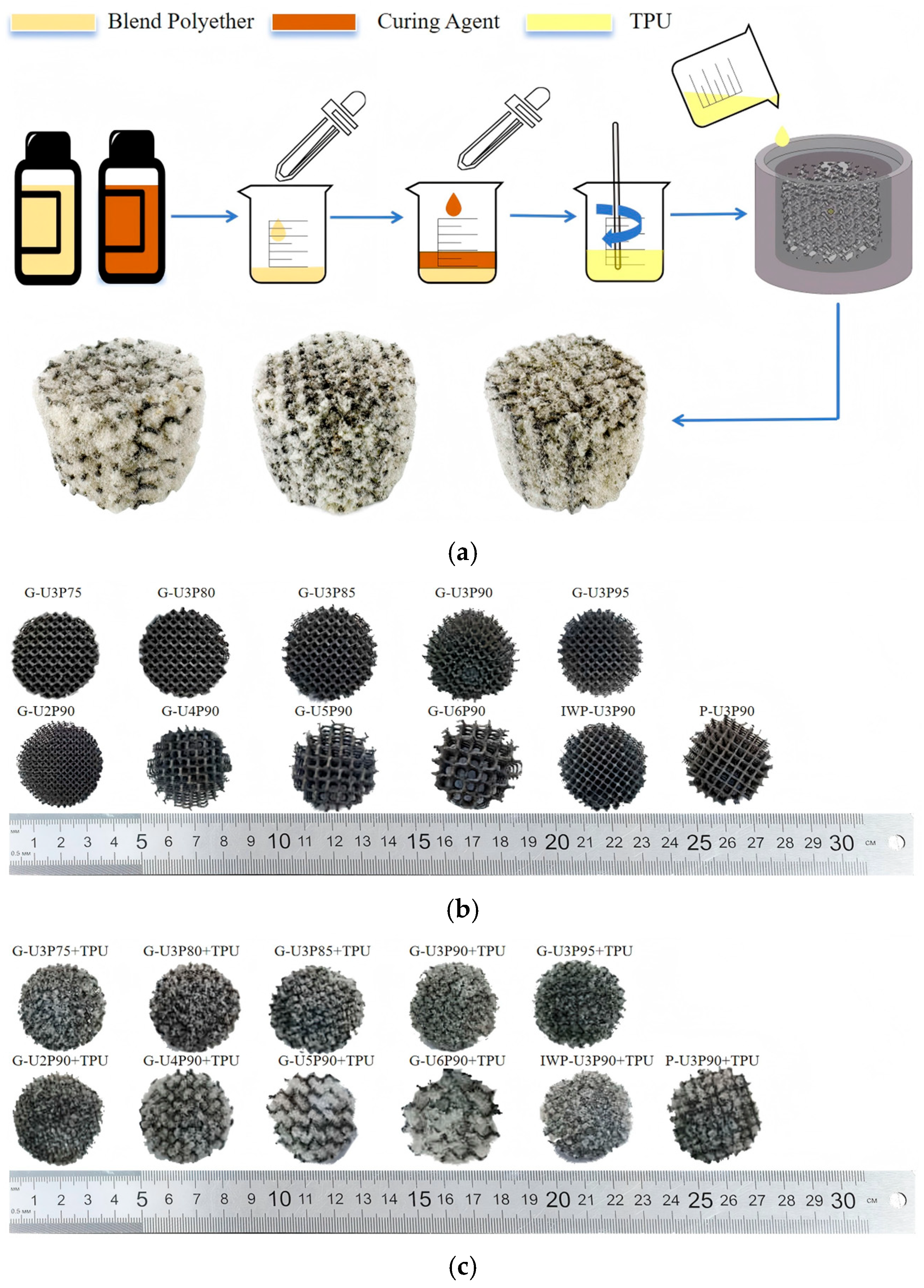
The fabrication of IPCs was facilitated by the utilization of dedicated silicone molds, which were designed and manufactured for this purpose. The process involved inserting pre-fabricated TPMS structures into the designated mold cavities. A two-component polyurethane system, consisting of a polyether polyol blend and an isocyanate-based curing agent (supplied by Changzhou Zhuolianzhichuang Polymer Materials Technology Co., Ltd., Changzhou, China), was mixed in a glass beaker at a 1:1 mass ratio. The mixture was stirred with a glass rod for 60 s to achieve uniform consistency.
To minimize the entrapment of air, it is necessary to pour the polyurethane blend slowly along the inner wall of the mold. The employment of this controlled pouring technique facilitated the process of foaming and expansion, thereby enabling the mixture to progressively infiltrate the pores of the AlSi7Mg framework, culminating in the complete encapsulation of the cylindrical structure. Following a two-hour room-temperature curing process, the specimens were demolded, and excess TPU was trimmed away. The process yielded AlSi7Mg/TPU IPCs specimens with three-dimensionally continuous interpenetrating networks. The schematic diagram of the fabrication process and the resulting samples is presented in Figure 4.
The TPMS structure and the resulting IPCs specimens (see Figure 2b and Figure 2c, respectively) both measure φ 29 mm × 20 mm. The designation G-U2P90+TPU refers to the IPCs specimen based on a gyroid specimen with a 2 mm unit cell and 90% porosity.

2.4. Specimen Test

2.4.1. Acoustic Test

The sound absorption coefficients and normal-incidence transmission loss (TL) of TPMS and IPCs structures were measured over the 500–6300 Hz frequency range using a two-microphone transfer-function impedance tube system (SW4661, BSWA Technology Co., Ltd., Beijing, China; 29 mm inner diameter, as shown in Figure 5) in accordance with ASTM E1050-12. The ambient laboratory conditions were maintained at 20–25 °C and 45–55% relative humidity during testing to ensure measurement accuracy and repeatability. The specimens were mounted at the impedance tube termination against a rigid backing. The determination of acoustic parameters was achieved through the utilization of Equations (4)–(10).
The two-microphone impedance tube method employs a one-dimensional rectangular coordinate system. In this system, the specimen surface serves as the reference plane (defined as x = 0), and the sound wave propagates along the x-axis.
The total sound pressure at the positions of microphone 1 and microphone 2, denoted as P1 and P2 respectively, represents the superposition of the incident and reflected waves in complex form. Their expressions are given by:
P 1 = P i e j k ( l + s ) + P r e j k ( l + s )
P 2 = P i e j k l + P r e j k l
where
Pi: The sound pressure amplitude (in complex form) of the incident sound wave at the reference plane (x = 0).
Pr: The sound pressure amplitude (in complex form) of the reflected sound wave at the reference plane (x = 0).
j: Imaginary unit (j2 = −1), used to describe the phase characteristics of sound waves.
k: Complex wavenumber (m−1), describing the phase characteristics of sound waves.
l: The distance from the center of the nearest microphone to the specimen surface (reference plane x = 0).
s: The distance between the centers of the two microphones.
The transfer function H is defined as the complex ratio of P2 to P1 and is calculated from Equation (6). This function is used for the subsequent calculation of the reflection coefficient.
H = P 2 P 1 = e j k ( l + s ) + R e j k ( l + s ) e j k l + R e j k l
R: Reflection coefficient (in complex form), representing the amplitude ratio of the reflected wave to the incident wave at the reference plane.
The R is derived by combining Equations (4)–(6).
R = H e j k s e j k s H e j 2 k ( l + s )
Equation (8) is used to calculate the sound absorption coefficient α.
α = 1 R 2
The 1/3-octave average sound absorption coefficient is calculated using Equation (8) at 12 discrete frequencies ranging from 500 Hz to 6300 Hz.
A α = α i 12
The acoustic absorption behavior of materials exhibits strong frequency dependence. Consequently, the first absorption peak was analyzed to determine the peak sound absorption coefficient α1 and the corresponding frequency f1.
TL quantifies the ability of a structure to block sound at normal incidence, with higher values indicating superior sound insulation performance. Expressed in decibels (dB), TL is calculated using Equation (10) [28].
T L = 10 log 10 ( W i / W t )
where Wi is the incident sound power and Wt is the transmitted sound power.

2.4.2. Compression Test

The quasi-static compressive properties of the designed monolithic gyroid structures and their cross-spending interpenetrating phase composites (IPCs) were characterized through uniaxial compression testing. The specimens included five monolithic gyroid variants (G-U3P75, G-U3P80, G-U3P85, G-U3P90, and G-U3P95) and five IPC counterparts (G-U3P75+TPU, G-U3P80+TPU, G-U3P85+TPU, G-U3P90+TPU, and G-U3P95+TPU).
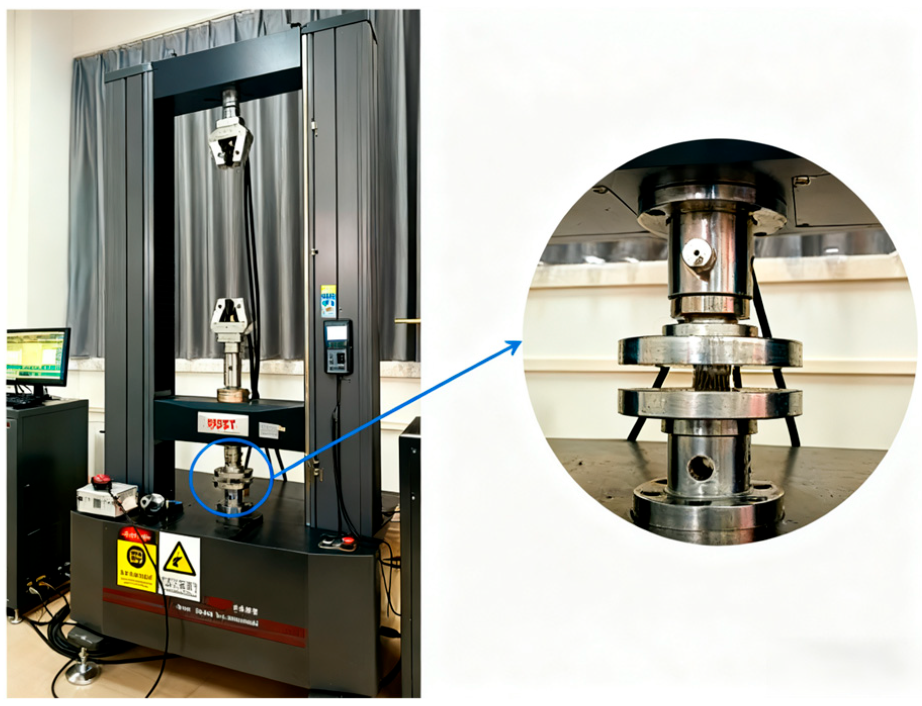
The tests were conducted in displacement-control mode at a crosshead speed of 2 mm/min using a CMT5105-100 kN electromechanical universal testing machine (Zhuhai Sansi Tajie Electric Equipment Co., Ltd., Zhuhai, China), as shown in Figure 6.
Compressive load and displacement were recorded using the machine’s integrated load cell (with ±0.5% accuracy) and a linear variable differential transformer (LVDT), respectively. According to the ISO 13314:2011 standard for porous metallic materials, the raw load–displacement data were converted into engineering stress–strain curves.
Energy absorption (per unit volume) serves as a key indicator for evaluating the performance of energy-absorbing materials. The energy absorption W(ε) is given by [29]:
W ( ε ) = 1 100 0 ε σ ( ε ) d ε
where ε represents a given strain value of the AlSi7Mg porous structure under compressive loading, and σ(ε) denotes the corresponding stress at that strain.
All integrations were performed using the numerical integration tool based on the trapezoidal rule in Origin 2021 software. For the monolithic metallic frameworks, which exhibited brittle collapse behavior, the integration cutoff was set at the strain where stress first decreased to 70% of the peak value, indicating the onset of structural failure. For the IPCs, which displayed typical porous material deformation characteristics, the integration was conducted up to the densification strain (ε). For the IPCs, integration was performed up to the densification onset strain, defined as the local stress minimum preceding the rapid stress increase, to ensure that the Specific Energy Absorption (SEA) values represent the effective energy absorption range for each material.
The specific energy absorption capacity for each structure variant was calculated from the stress–strain curves of multiple independent samples. The results are presented as the mean value with 95% confidence intervals (CI)with n = 3.

3. Results and Discussion

3.1. Sound Absorption Performance Analysis

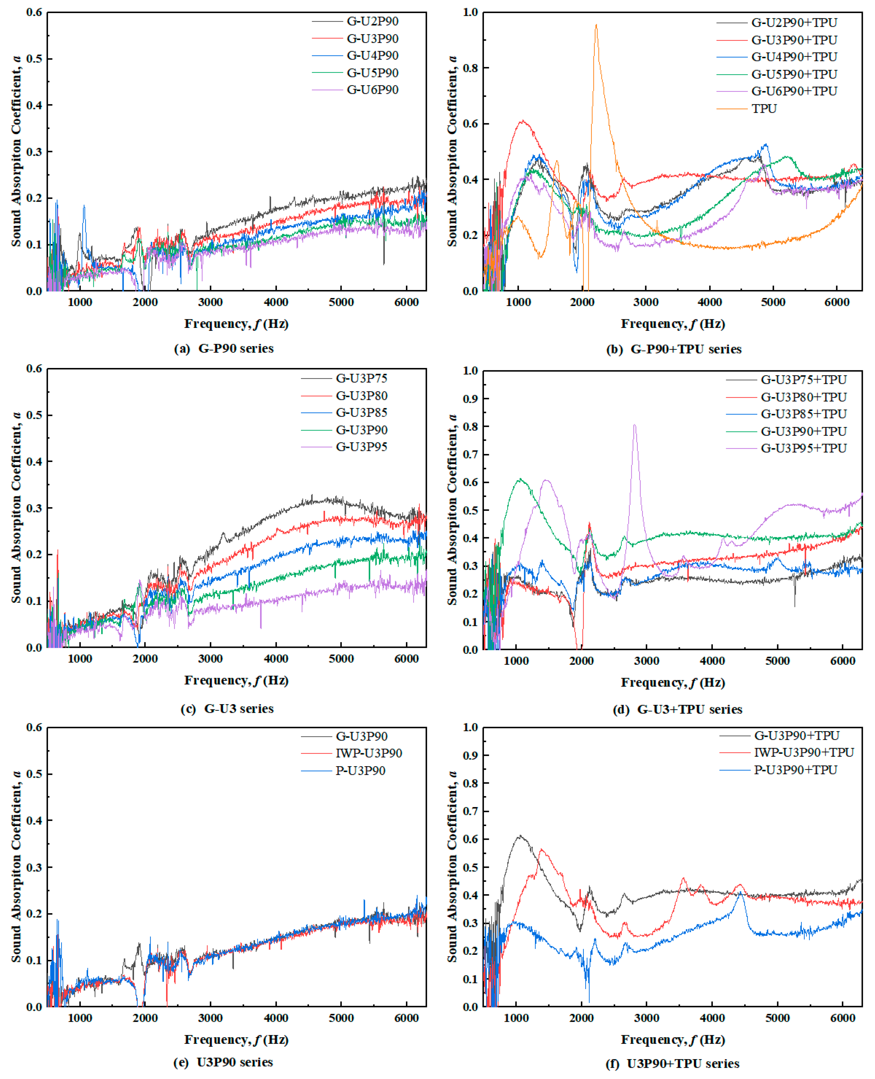
The following sections present a detailed analysis of the sound absorption properties of TPMS lattices and IPC structures, including the average sound absorption coefficient (αave), the first-peak absorption coefficient (α1), and the corresponding frequency (f1) over the range of 500–6300 Hz. This analysis is illustrated in Figure 7 and further elaborated in Table 2 and Table 3. In the case of unfilled TPMS lattices, the value of αave is consistently found to be less than 0.2, which is significantly below the industrial noise-abatement threshold. In the context of IPC configurations, G-U3P90+TPU has been shown to exhibit the best acoustic performance in this study, as evidenced by the following parameters αave = 0.393 and α1 = 0.616. When compared to its unfilled G-U3P90 counterpart (αave = 0.086, α1 = 0.225) at identical porosity and unit-cell dimensions, the composite shows a 4.57-fold enhancement in αave and 2.74-fold improvement in α1. This significant enhancement highlights the synergistic effect of TPU infiltration and structural optimization on broadband absorption.

3.1.1. Unit Cell Size

For unfilled aluminum alloy gyroid structures, the sound absorption coefficient increases significantly with the unit cell size. This phenomenon is characterized by the manifestation of a single absorption peak in the high-frequency region. When the minimal unit cell size of IPC configurations varies within the 2–6 mm range (1 mm increments), all absorption curves consistently display three distinct absorption peaks. In comparison with unfilled aluminum alloy gyroid structures that possess identical porosity and unit cell dimensions, IPC structures exhibit a 94.8%–183.2% enhancement in α1, accompanied by a distinct downward shift in f1. It is noteworthy that f1 migrates to 1060 Hz in the G-U3P90+TPU specimen. The experimental data identify the structure with a unit cell size of 3 mm (G-U3P90+TPU, α1 = 0.616) as the empirically optimal performer under the tested conditions, suggesting that this specific geometry facilitates highly effective damping dissipation by the TPU while effectively shifting the dominant absorption peak to lower frequencies. A theoretical model to predict this specific optimum remains to be established.

3.1.2. Porosity

For unfilled aluminum alloy gyroid structures, the sound absorption behavior exhibits systematic variations as the porosity increases from 75% to 95% in 5% increments. Specifically, the peak sound absorption coefficient (α1) shows a monotonic decrease from 0.33 to 0.168. In contrast, the corresponding peak frequency (f1) remains confined to the high-frequency range of 4546–6296 Hz. These results demonstrate that elevated porosity reduces the peak absorption coefficients, thereby shifting the effective sound absorption to higher frequencies.
For the IPCs, the influence of porosity was further investigated by testing the TPU mass fraction as a covariate. The analysis confirms that the downward shift of f1 to lower frequencies with increasing porosity remains the dominant trend, independent of variations in TPU filling. For instance, within the G-U3P series, samples with comparable TPU mass fractions (e.g., G-U3P85+TPU at 17.7% and G-U3P90+TPU at 20.0%) exhibit a clear decrease in f1 from 1042 Hz to 1060 Hz as porosity increases. This consistent pattern across a range of TPU mass fractions (13.0% to 21.3%) robustly demonstrates that porosity, rather than the degree of pore filling, is the primary factor controlling the resonant frequency. α1 increases by 92% (0.32 to 0.616) as porosity rises from 75% to 90%, due to improved pore connectivity that enhances viscoelastic damping. However, α1 drops to 0.55 at 95% porosity, suggesting excessive porosity undermines TPU’s dissipation. The f1 peak shifts to lower frequencies with rising porosity, consistent with Helmholtz resonance. The G-U3P90+TPU composite at 90% porosity demonstrated the best performance in the experiments, achieving a peak α1 of 0.616 at 1060 Hz, which suggests that efficient acoustic impedance matching is achieved between the porous structure and damping phase.

3.1.3. Structural Topology

At identical porosity (90%), the sound absorption coefficient curves of unfilled TPMS lattices—gyroid (G-U3P90), IWP (IWP-U3P90), and Primitive (P-U3P90)—show negligible differences, with coefficients consistently below 0.2, rendering them ineffective for noise reduction. Following TPU infiltration, the sound absorption performance of the IPCs diverges significantly: G-U3P90+TPU demonstrated superior performance, achieving α1 = 0.616. This represents a 1.086-fold enhancement over IWP-U3P90+TPU (α1 = 0.567) and a 1.456-fold enhancement over P-U3P90+TPU (α1 = 0.423). G -U3P90+TPU also demonstrates superior broadband absorption, with its half-absorption bandwidth expanding to 858–1370 Hz.
The performance hierarchy (Gyroid > IWP > Primitive) originates from the fundamental differences in how each structural topology couples with viscoelastic dissipation mechanisms.
Gyroid Structure: Its high specific surface area and continuous, smoothly curved helical channels maximize multi-stage flow regulation, enabling global synergistic viscoelastic-damping coupling. This facilitates efficient broadband sound absorption.
Primitive Structure: Its acoustic performance is constrained by narrow-band cavity resonance. Although Helmholtz-type resonance coupling occurs, the relatively straight flow channels limit multi-stage flow regulation. Furthermore, compartmentalized cavities impede global viscoelastic damping coupling.
IWP Structure: A key finding of this study is that straight ligament pathways restrict sufficient dissipation paths for low-frequency sound waves. While localized viscoelastic-damping coupling is activated at the nodes, the overall absorption performance remains intermediate between the gyroid and primitive structures.

3.2. Transmission Loss Analysis

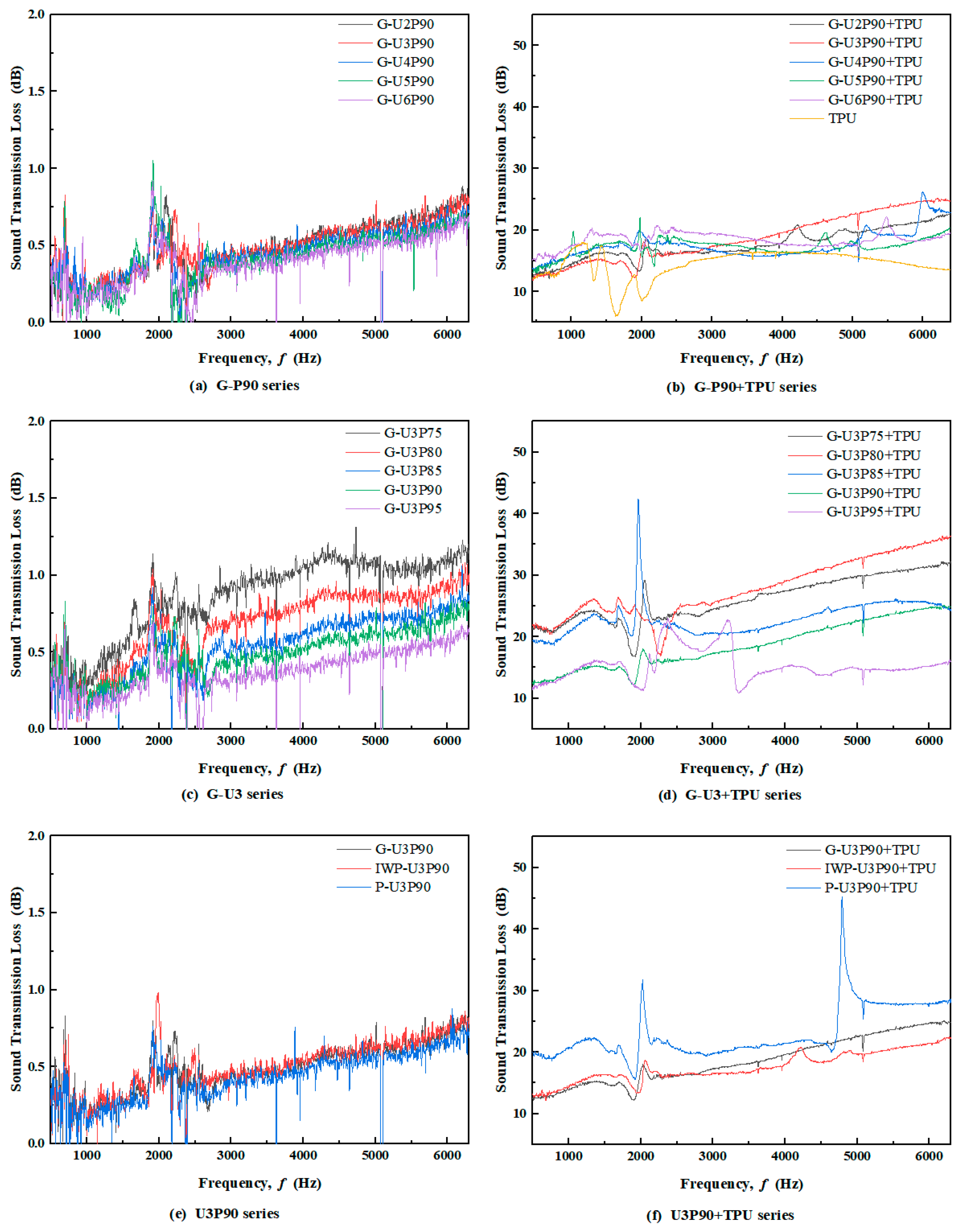
The average normal transmission loss (TLave), maximum normal transmission loss (TLmax), and the corresponding peak frequency (fmax) of both TPMS and IPCs structures within the 500–6300 Hz range are presented in Figure 8 and Table 4 and Table 5.
The structures of the TPMS models, devoid of TPU infill, demonstrated a uniform performance, exhibiting TLave values below 1 dB across the entire frequency band. This finding indicates that the sound insulation performance of the models fails to meet the threshold required for practical engineering applications.
In contrast, TPU foam infusion markedly enhanced the acoustic performance of the IPC structures. Notably, the G-U3P80+TPU composite achieved an average transmission loss (TLave) of 25.544 dB and a maximum TL (TLmax) of 34.437 dB at 6180 Hz. These values represent a 48.7-fold and a 31.9-fold increase in TLave and TLmax, respectively, over the unfilled G-U3P80 structure, accompanied by a slight shift in the peak frequency. The results unequivocally demonstrate the superior sound insulation capability of the G-U3P80+TPU configuration.

3.2.1. Unit Cell Size

As the unit cell size increases from 2 mm to 6 mm, the average transmission loss (TLave) of the unfilled aluminum alloy gyroid structures shows a marked decrease. This result is consistent with the previously reported finding that a larger number of cellular layers enhances the sound insulation of lattice-type TPMS sandwich cores [30]. Together, these results demonstrate that the structural unit size is a critical tuning parameter for the acoustic performance of TPMS-based structures.
The IPC structures demonstrate significantly superior TLave values in comparison to their aluminum alloy TPMS counterparts, exhibiting an overall enhancement that exceeds 16 dB. However, the frequency response curves of these composites remain relatively flat over the tested frequency range (with fluctuations within ±6.5 dB), suggesting that although they provide stable broadband acoustic insulation, there remains considerable room for further improvement.

3.2.2. Porosity

As porosity increases from 75% to 95%, the average transmission loss (TLave) of the unfilled aluminum alloy gyroid structures exhibits an overall decreasing trend. This observation is consistent with the findings reported by Wu et al. [31], indicating that higher porosity generally correlates with reduced sound insulation performance.
The underlying mechanism is that increased porosity reduces the structure’s overall density and stiffness, thereby providing less resistance to sound wave propagation. This makes the structure more acoustically transparent, allowing a larger portion of incident sound energy to transmit, which in turn leads to decreased transmission loss.
The incorporation of TPU has been demonstrated to significantly enhance the sound insulation performance of the material. For instance, the G-U3P80+TPU composite demonstrates a significant enhancement, with TLave increasing to 25.544 dB—48.7 times higher than that of its unfilled counterpart, G-U3P80 (TLave = 0.524 dB), at the same porosity and unit cell size. The significant improvement is attributed to the TPU infill, which drastically alters the sound path. The viscoelastic matrix adds mass, seals pores, and forces sound waves to travel through a dissipative medium, thereby enhancing energy dissipation and transmission loss. This outcome provides substantial validation for the highly efficient sound insulation mechanism of the IPC structures.
Within the gyroid U3P series, TLave initially increases with the TPU mass fraction, reaching an optimum around G-U3P80+TPU TLave: 25.54 dB at 14.7% TPU) and G-U3P85+TPU (TLave: 21.99 dB at 17.7% TPU), before decreasing at higher TPU fractions. This non-monotonic trend demonstrates that the TPU mass fraction alone is not a straightforward predictor of performance. Instead, its effect is modulated by the host structure’s porosity and topology, which govern the mechanical coupling and wave propagation path.

3.2.3. Structural Topology

It is evident from the data presented that at a porosity of 90%, the unfilled aluminum TPMS structures—Gyroid (G-U3P90), IWP (IWP-U3P90), and Primitive (P-U3P90)—exhibit nearly identical average transmission loss (TLave). This outcome validates the hypothesis that, in the absence of TPU filler, the specific topological type of TPMS exerts a negligible influence on the baseline sound insulation performance. The sound insulation of the pure metallic lattice is primarily dependent on its density and stiffness, rather than on its topological architecture.
Following the infiltration of TPU, the sound insulation performance of the IPC structures exhibits significant variations in accordance with their topology. Notably, the IPC-U3P90+TPU structure demonstrates a high TLave of 45.2 dB, attributable to its enclosed cellular cavities that function as acoustic spring-mass systems. While sound waves excite vibrations in the TPU-filled cavity walls to generate a significant insulation peak at resonance, the uninterrupted helical flow channels of G-U3P90+TPU facilitate multi-path sound wave interference, which, combined with TPU damping, achieves a remarkable TLmax of 25.121 dB. IWP-U3P90+TPU, distinguished by its straight ligaments, facilitates efficient vibration transmission but offers inadequate damping dissipation, resulting in a TLmax of 22.457 dB.

3.3. Compressive Performance Analysis

Uniaxial quasi-static compression tests were performed on both the unfilled aluminum alloy gyroid structure and the corresponding IPCs, with the results illustrated in Figure 9. As previously demonstrated, the stress–strain curve of the aluminum alloy gyroid displays three distinct stages: elastic deformation, yielding, and brittle fracture. In contrast, the IPCs continue to exhibit further evolution of the stress–strain curve following the initial brittle fracture, exhibiting a distinctive fluctuating yield plateau. The topography of the plateau is distinguished by its notable length and undulating nature. In comparison with the aluminum alloy gyroid structure, the yield plateau of the IPCs occupies over 60% of the deformation range, thereby significantly extending the energy absorption phase before structural failure.

3.3.1. Elastic Modulus Analysis

As porosity increases, both the first compressive strength and the elastic modulus of the gyroid structures and the IPCs show a decreasing trend.
As shown in Figure 9f, the specific strain data for the aluminum alloy gyroid structures are presented. As porosity increases from 75% to 95%, the elastic modulus of the aluminum alloy Gyroid structures decreases exponentially, from 550.92 ± 54.07 MPa (G-U3P75) to 9.06 ± 1.29 MPa (G-U3P95), representing a 98.4% reduction.
Figure 9f shows the specific strain data for the aluminum alloy gyroid structures. As porosity increases from 75% to 95%, the elastic modulus of the aluminum alloy Gyroid structures decreases exponentially, from 550.92 ± 54.07 MPa (G-U3P75) to 9.06 ± 1.29 MPa (G-U3P95), representing a 98.4% reduction. This phenomenon aligns closely with the Gibson–Ashby model for porous materials, which posits that the structural stiffness is proportional to the square of the relative density. A 5% increase in porosity reduces this key parameter, thereby substantially elevating the stress concentration factor. The observed 45° shear band fracture (as shown in Figure 10) provides direct evidence of localized yield induced by high stress concentration. It is important to note that once porosity exceeds the critical value of 85%, a modulus collapse occurs. In this case, the continuous load-bearing network of the metal framework collapses, accompanied by a sharply accelerating decline in the load-bearing area.
A comparison of the IPCs with the unitary aluminum alloy Gyroid structures reveals significant reductions in elastic modulus, with values of 100.4 MPa, 79.50 MPa, 55.76 MPa, 31.87 MPa, and 3.54 MPa, respectively. These reductions correspond to 18.22%, 23.9%, 24.24%, 34.91%, and 39.10% of the original values, highlighting the efficacy of the IPCs in reducing the elastic modulus. The reduction in elastic modulus manifests in a two-stage manner:
Porosity in this region ranges from 75% to 85%. The modulus reduction exhibited stability at 18%–24%. The TPU compensates for skeletal damage through microcrack bridging, and its viscoelastic behavior effectively delays stress concentration.
The high-porosity region (defined as ≥90%) is a critical component of the study. The modulus reduction increased significantly to 34.9%–39.1%. In this scenario, the effective load-bearing area of the metal framework falls below 15%, leading to fractured stress transfer paths. The fracture of stress-transfer pathways, in conjunction with interfacial slip at the TPU–aluminum interface [31], results in the collapse of the equivalent modulus [32].

3.3.2. Failure Behavior Analysis

As porosity increases from 75% to 95%, the failure behavior of the aluminum alloy Gyroid structures undergoes a significant evolution, as detailed in Figure 10.
In the range of 75% to 85% porosity, the compressive failure strain maintains a value of approximately 15%, exhibiting a diagonal shear band fracture consistent with the collapse mode of TPMS structures [30].
Once porosity exceeds 85%, the failure mode transitions to localized brittle collapse. Specifically, at porosity exceeding 90%, hydrostatic pressure increases pronouncedly, disrupting the triaxial stress equilibrium. The influence of distortions in the stress field results in a shift of the shear band angle to 60° ± 5° and a decrease in the compressive failure strain to approximately 8%, which aligns with the observations made by Zhang using digital image correlation (DIC) [26].
In contrast, the IPCs exhibit progressive crushing failure throughout the compression process, without forming macroscopic shear bands but accompanied by significant lateral expansion, consistent with reported failure modes [19].
At porosities ranging from 75% to 85%, the TPU mitigates skeletal fracture through its viscoelastic constraints, while the polymer phase within the pores dissipates energy by deforming extensively.
When porosity exceeds 85%, the metallic skeleton effectively degrades into a discrete reinforcing phase, and failure becomes dominated by volumetric compression of the TPU matrix. The lateral expansion results from Poisson effects induced by interfacial debonding.

3.3.3. Energy Absorption Analysis

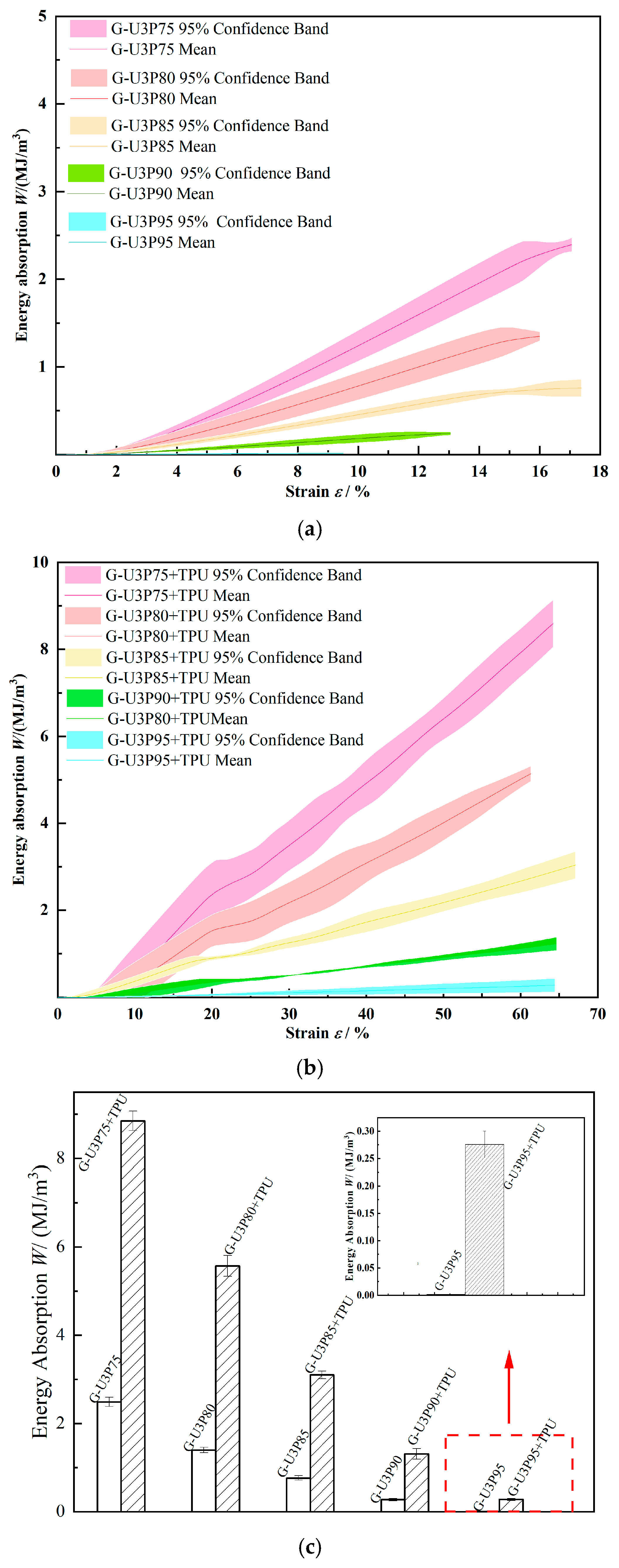
As shown in Figure 11, the energy absorption capacity of aluminum alloy gyroid structures decreases with increasing porosity. A substantial decrease of 99.9% was observed from G-U3P75 (2.4890 ± 0.1047 MJ/m3, mean ± 95% CI, n = 3) to G-U3P95 (0.0017 ± 0.0001 MJ/m3), with G-U3P75 serving as the reference point. This trend aligns with the failure-porosity relationship documented by Zhang et al. [33]. When porosity exceeds 85%, the inflection point in energy absorption shifts forward from 20% strain (G-U3P75). At an initial porosity level of 95%, the observed inflection point occurs at an early strain level of 8%. The distribution of internal stress is highly uneven, resulting in localized deformation-dominated failure. This phenomenon triggers a near-complete collapse of energy absorption capacity. This finding is consistent with the results reported by Li et al. on the failure mechanisms of porous AlSi10Mg structures with varying porosities [30].
Under quasi-static compression, the IPCs exhibit a substantial, graded enhancement in energy absorption. The energy absorption of G-U3P75+TPU (8.8493 ± 0.2198 MJ/m3) is 3.56 times that of the unfilled G-U3P75. This increase in energy absorption is primarily due to TPU pore filling and interfacial strengthening. This mechanism transforms the failure mode from brittle fracture of the matrix to a multi-stage energy dissipation mechanism involving crack bridging, plastic deformation, and viscoelastic damping [34].
The G-U3P95+TPU composite exhibited an energy absorption capacity of 0.2762 ± 0.0244 MJ/m3, representing a remarkable increase (162.5 fold) over the unfilled G-U3P95 structure. This nano-confinement facilitates the dominance of TPU in energy dissipation through non-affine large-scale deformation of molecular chains. Consequently, the role of TPU shifts fundamentally from a toughening agent to the primary energy-absorbing phase [35].

3.4. Comprehensive Performance Analysis

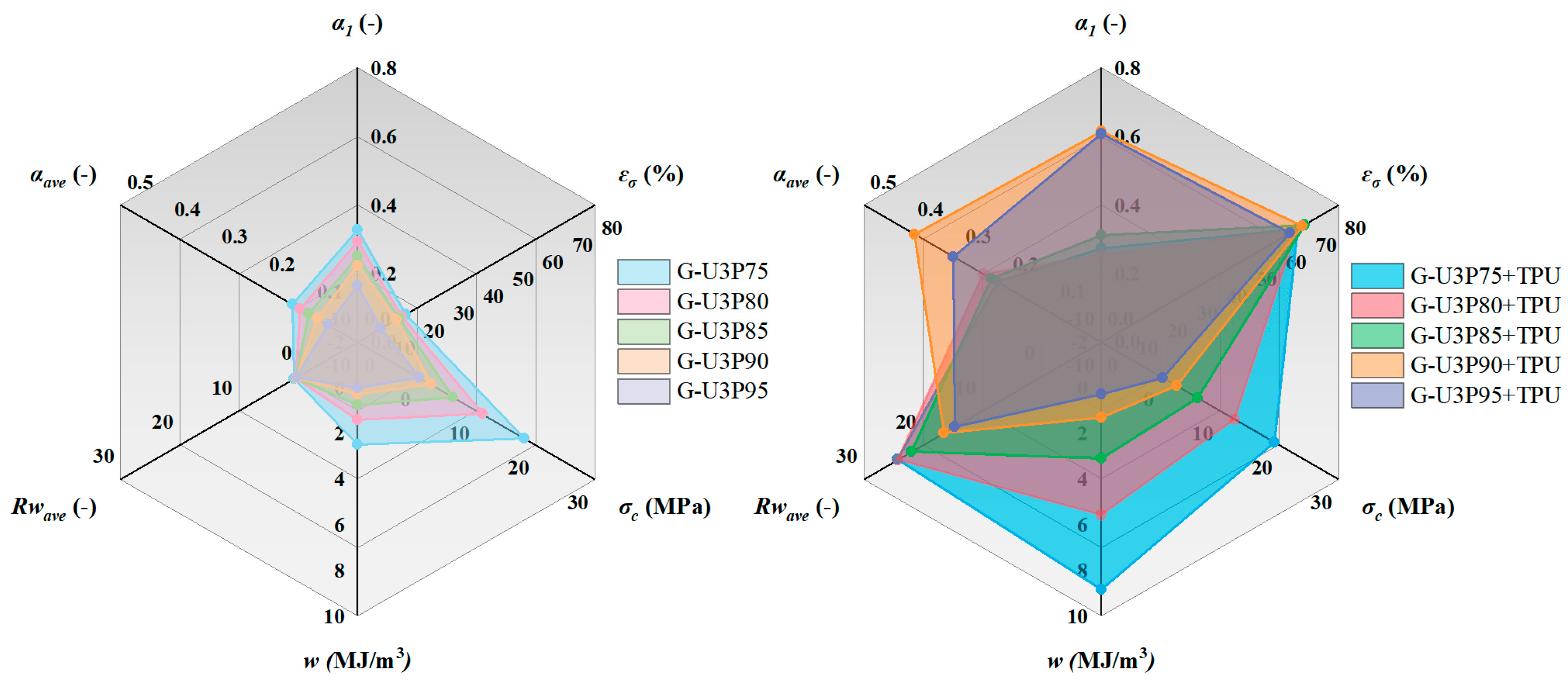
Figure 12 provide a quantitative comparison of the acoustic-mechanical coupling performance of the TPMS and IPC structures.
Among the aluminum alloy gyroid structures tested in this study, G-U3P75 demonstrated the best overall performance, exhibiting superior sound absorption coefficient (αave = 0.138, α1 = 0.330), energy absorption (w = 2.4890 MJ/m3), compressive strength (σc = 34.5 MPa), and pre-collapse strain (εσ = 15%). However, its average sound transmission loss (TLave < 1 dB) is governed by the mass law and therefore fails to meet the engineering application threshold (>15 dB) [25].
TPU, with its high viscoelasticity and intrinsic damping, optimizes the sound absorption pathways within the IPC structures at the microstructural level, thereby enhancing their sound absorption efficiency [36]. Altering sound wave propagation can enhance sound absorption by extending the propagation path and promoting mode conversion, thereby improving sound insulation.
G-U3P75+TPU demonstrates superior sound insulation properties, with a mean transmission level (TLave) of 25.5 dB, substantial energy absorption capacity (w = 8.85 MJ/m3), and notable compressive strength (σc = 42.3 MPa). However, its limitations are evident in its suboptimal sound absorption performance (αave = 0.22, half-absorption bandwidth < 400 Hz).
G-U3P90+TPU exhibits noteworthy sound absorption properties (αave ≥ 0.393, α1 = 0.616). The half-absorption bandwidth of this material extends from 858 to 1370 Hz. However, the material experiences a decline in mechanical properties (σc = 8.7 MPa, w = 1.31 MJ/m3).
The G-U3P80+TPU model achieves a balanced acoustic-mechanical design, a key engineering objective. The synergy between Helmholtz resonators and interfacial damping enables a balanced performance output (TLave is 18.6 dB, αave is 0.28, and w is 5.57 MJ/m3).
In the context of high-load-bearing applications, such as those pertinent to aerospace cabin connectors, G-U3P75+TPU emerges as the primary candidate material. The σc is 40 MPa, w is 8.85 MJ/m3, and TLave > 25 dB. Surface micro-arc oxidation can be applied to enhance interfacial strength and compensate for its limited sound absorption performance.
In scenarios involving broadband sound absorption (e.g., in the context of engine compartment liners), G-U3P90+TPU is recommended based on its performance, with αave > 0.35 and a half-absorption bandwidth exceeding 500 Hz. Acknowledging its mechanical trade-off (σc = 8.7 MPa), its use should be limited to non-primary load-bearing roles. This limitation can be mitigated by integrating topology-optimized ribs, while future work may explore MAO treatment or enhanced interfacial bonding for further mechanical improvement.
For integrated acoustic-structural applications, such as the flooring of high-speed vehicles, G-U3P80+TPU presents a balanced choice (TLave > 18 dB, αave > 0.25, and w > 5 MJ/m3). The instrument’s balanced performance is the result of the synergistic action of Helmholtz resonance and damping mechanisms.

4. Conclusions

A design and fabrication methodology for triply periodic minimal surface (TPMS)-structured interpenetrating phase composites (IPC) is proposed in this study. The acoustic properties and compressive performance of these IPC structures were investigated through acoustic impedance tube testing and quasi-static compression experiments. The conclusions were obtained as follows:
(1).
IPC configurations acoustically outperform unfilled aluminum alloy TPMS structures. The first peak of the acoustic absorption coefficient shifts to lower frequencies, and the average absorption coefficient within the 500–6300 Hz range increases by a factor of 1.59. Furthermore, the composites demonstrate a substantial improvement in sound insulation, with the average normal incidence transmission loss (TL) enhanced by a factor of 35.58.
(2).
It has been demonstrated that unfilled aluminum alloy gyroid structures exhibit abbreviated yield plateaus. Within the 75%–85% porosity range, compressive failure occurs at approximately 15% strain. This failure is primarily due to 45° shear-band brittle fracture. When porosity exceeds 85%, the failure mechanism transitions to localized brittle collapse. Specifically, at porosities greater than 90%, the compressive failure strain is reduced to approximately 8%, and the shear-band angles deviate to 60° ± 5°, a consequence of stress field distortion. Following TPU infiltration, the IPC structures develop ductile plateaus exceeding 60% strain under quasi-static compression, accompanied by substantial enhancement in energy absorption performance. G-U3P75+TPU demonstrated the best energy absorption characteristics, based on experimental data presented as mean ± 95% CI (n = 3).
(3).
The AlSi7Mg/TPU interpenetrating-phase configuration has been demonstrated to enhance acoustic absorption, sound insulation, and compressive performance in porous structures. The synergy of these properties makes the proposed IPCs highly suitable for advanced applications, including aerospace interiors, vibration–isolation platforms, transportation components, and specialized acoustic structures.

Author Contributions

All authors contributed to the study conception and design. Conceptualization, Y.W. and M.Z.; methodology, M.Z. and S.Y.; software, M.Z. and F.L.; validation, Y.L. and F.L.; formal analysis, Y.L. and J.F.; investigation, Y.W. and J.F.; resources, M.Z.; data curation, S.Y. and F.L.; writing—original draft preparation, Y.W.; writing—review and editing, F.L.; visualization, Y.W. and J.F.; supervision, Y.L. and F.L.; project administration, Y.W. and M.Z.; funding acquisition, Y.W. and M.Z. All authors have read and agreed to the published version of the manuscript.

Funding

This research was funded by Guangdong Provincial Program for Young Innovative Talents in Regular Higher Education Institutions (No. 2023KQNCX257) and Guangdong Basic and Applied Basic Research Foundation (No. 2023A1515012704).

Institutional Review Board Statement

Not applicable.

Informed Consent Statement

Not applicable.

Data Availability Statement

Data are contained within the article.

Conflicts of Interest

The authors declare that the research was conducted in the absence of any commercial or financial relationships that could be construed as a potential conflict of interest.

References

  1. Liu, Z.Q.; Gong, H.; Gao, J.Z. Enhancement in the fatigue resistances of triply periodic surfaces-based scaffolds. Int. J. Mech. Sci. 2023, 245, 108119. [Google Scholar] [CrossRef]
  2. Gao, T.Y.; Liu, K.; Wang, X.X.; Shen, L.M.; Zhao, Y.M.; Wei, K.; Wang, Z.G. Elastic wave manipulation via functional incorporation of air-solid phases in hybrid TPMS. Compos. Commun. 2023, 44, 101745. [Google Scholar] [CrossRef]
  3. Nguyen-Van, V.; Choudhry, N.K.; Panda, B.; Nguyen-Xuan, H.; Tran, P. Performance of concrete beam reinforced with 3D printed Bioinspired primitive scaffold subjected to three-point bending. Autom. Constr. 2022, 134, 104060. [Google Scholar] [CrossRef]
  4. Tang, W.; Zhou, H.; Zeng, Y.; Yan, M.L.; Jiang, C.L.; Yang, P.; Li, Q.; Li, Z.D.; Fu, J.H.; Huang, Y.; et al. Analysis on the convective heat transfer process and performance evaluation of Triply Periodic Minimal Surface (TPMS) based on Diamond, Gyroid and Iwp. Int. J. Heat Mass Transf. 2023, 201, 123642. [Google Scholar] [CrossRef]
  5. Min, R.; Wang, Z.H.; Yang, H.N.; Bao, R.Q.; Zhang, N.J. Heat transfer characterization of waste heat recovery heat exchanger based on flexible hybrid triply periodic minimal surfaces (TPMS). Int. J. Heat Mass Transf. 2024, 157, 107760. [Google Scholar] [CrossRef]
  6. Baobaid, N.; Ali, M.I.; Khan, K.A.; Abu Al-Rub, R.K. Fluid flow and heat transfer of porous TPMS architected heat sinks in free convection environment. Case Stud. Therm. Eng. 2022, 33, 101944. [Google Scholar] [CrossRef]
  7. Fu, M.; Chang, L.; Mahmoud, H.A. Enhancing the efficiency and energy capacity of the improved airplane body under external maneuvering loads. Aerosp. Sci. Technol. 2024, 151, 109255. [Google Scholar] [CrossRef]
  8. Wei, Y.P.; Li, H.Q.; Han, J.J.; Ma, Y.C.; Zhou, H.R.; Cheng, J.C.; Shi, J.; Miao, Z.Q.; Yu, B.; Lin, F. Mechanical and damping performances of TPMS lattice metamaterials fabricated by laser powder bed fusion. China Foundry 2024, 21, 327–333. [Google Scholar] [CrossRef]
  9. Cheng, Z.L.; Xu, R.N.; Jiang, P.X. Morphology, flow and heat transfer in triply periodic minimal surface based porous structures. Int. J. Heat Mass Transf. 2021, 170, 120902. [Google Scholar] [CrossRef]
  10. Zeng, C.J.; Hu, J.Q.; Liu, L.W.; Zhao, W.; Xin, X.Z.; Song, X.H.; Liu, Y.J.; Leng, J.S. Mechanical properties of diamond-type triply periodic minimal surface structures fabricated by photo-curing 3D printing. Compos. Struct. 2025, 352, 118695. [Google Scholar] [CrossRef]
  11. Hou, Y.; Li, Y.J.; Cai, X.M.; Pan, C.L.; Wang, J.Y.; Zhang, W.; Xu, P.; Fan, Z.Q.; Gao, Y.B.; Li, Z.H.; et al. Mechanical response and response mechanism of AlSi10Mg porous structures manufactured by laser powder bed fusion: Experimental, theoretical and numerical studies. Mater. Sci. Eng. A-Struct. Mater. Prop. Microstruct. Process. 2022, 849, 143381. [Google Scholar] [CrossRef]
  12. Zhang, L.; Feih, S.; Daynes, S.; Chang, S.; Wang, M.Y.; Wei, J.; Lu, W.F. Energy absorption characteristics of metallic triply periodic minimal surface sheet structures under compressive loading. Addit. Manuf. 2018, 23, 505–515. [Google Scholar] [CrossRef]
  13. Santos, S.; Matos, C.; Duarte, I.; Olhero, S.; Miranda, G. Effect of TPMS reinforcement on the mechanical properties of aluminium–alumina interpenetrating phase composites. Prog. Addit. Manuf. 2024, 6, 1187–1199. [Google Scholar] [CrossRef]
  14. Li, Z.; Mo, H.; Tian, J.; Li, J.; Xia, S.; Jia, X.; Zhou, L.; Lu, Y. Compressive properties and fracture behaviours of Ti/Al interpenetrating phase composites with additive-manufactured triply periodic minimal surface porous structures. Met. Mater. Int. 2024, 31, 955–970. [Google Scholar] [CrossRef]
  15. Singh, A.; Karathanasopoulos, N. Static and dynamic damping mechanical performance of architected metal-epoxy interpenetrating phase composites. Compos. Part A Appl. Sci. Manuf. 2024, 182, 108171. [Google Scholar] [CrossRef]
  16. Zhang, P.F.; Li, Z.H.; Liu, B.; Zhou, Y.J.; Zhao, M.; Sun, G.H.; Pei, S.C.; Kong, X.N.; Bai, P.K. Sound absorption performance of micro-perforated plate sandwich structure based on triply periodic minimal surface. J. Mater. Res. Technol. -JMRT 2023, 27, 386–400. [Google Scholar] [CrossRef]
  17. Lin, C.G.; Wen, G.L.; Yin, H.F.; Wang, Z.P.; Liu, J.; Xie, Y.M. Revealing the sound insulation capacities of TPMS sandwich panels. J. Sound Vib. 2022, 540, 117303. [Google Scholar] [CrossRef]
  18. Li, Z.H.; Zhou, Y.J.; Kong, X.N.; Zhang, P.F.; Pei, S.C.; Ge, L.P.; Nie, Y.F.; Liu, B. Sound absorption performance of a micro-perforated plate sandwich structure based on selective laser melting. Virtual Phys. Prototyp. 2024, 19, 2321607. [Google Scholar] [CrossRef]
  19. Wang, K.D.; Wang, H.; Zhang, J.Q.; Fan, X.L. Mechanical behavior of interpenetrating phase composite structures based on triply periodic minimal surface lattices. Compos. Struct. 2024, 337, 118044. [Google Scholar] [CrossRef]
  20. Fan, Z.Q.; Zhang, B.B.; Liu, Y.B.; Suo, T.; Xu, P.; Zhang, J.J. Interpenetrating phase composite foam based on porous aluminum skeleton for high energy absorption. Polym. Test. 2021, 93, 106917. [Google Scholar] [CrossRef]
  21. Liu, S.; Li, A.; Xuan, P. Mechanical behavior of aluminum foam/polyurethane interpenetrating phase composites under monotonic and cyclic compression. Compos. Part A Appl. Sci. Manuf. 2019, 116, 87–97. [Google Scholar] [CrossRef]
  22. Canale, G.; Esperto, V.; Rubino, F. A Finite Element Analysis Framework for Assessing the Structural Integrity of Aero-Engine Ceramic Matrix Composite Component Coatings. Metals 2025, 15, 328. [Google Scholar] [CrossRef]
  23. Schoen, A.H. Infinite Periodic Minimal Surfaces Without Self-Intersections; National Aeronautics and Space Administration: Washington, DC, USA, 1970; Volume 5541. [Google Scholar]
  24. Zhang, M.K.; Li, J.W.; Liu, C.; Deng, M.J.; Liao, X.; Wang, D. Study on the Anisotropy of Triply Periodic Minimal Surface Porous Structures. Coatings 2023, 13, 1206. [Google Scholar] [CrossRef]
  25. MATLAB 9.11 (R2021b); The MathWorks Inc.: Natick, MA, USA, 2021.
  26. Zhang, M.K.; Liu, C.; Deng, M.J.; Li, Y.H.; Li, J.W.; Wang, D.; Ancona, A. Graded Minimal Surface Structures with High Specific Strength for Broadband Sound Absorption Produced by Laser Powder Bed Fusion. Coatings 2023, 13, 1950. [Google Scholar] [CrossRef]
  27. Zhang, M.; Deng, M.; Wang, G.; Yin, S.; Liu, W.; Liu, C.; Chen, J. Multicavity structures with triply periodic minimal surface for broadband and perfect sound absorption manufactured by laser powder bed fusion. Mater. Sci. Addit. Manuf. 2025, 4, 5737. [Google Scholar] [CrossRef]
  28. Wu, Y.; Qi, X.; Sun, L.; Wang, B.; Hu, L.; Wang, P.; Li, W. Sound transmission loss and bending properties of sandwich structures based on triply periodic minimal surfaces. Thin-Walled Struct. 2024, 204, 112324. [Google Scholar] [CrossRef]
  29. Zhang, M.K.; Yang, Y.Q.; Xu, M.Z.; Chen, J.; Wang, D. Mechanical properties of multi-materials porous structures based on triply periodic minimal surface fabricated by additive manufacturing. Rapid Prototyp. J. 2021, 27, 1681–1692. [Google Scholar] [CrossRef]
  30. Li, Y.N.; Zhan, J.; Song, C.H.; Yan, Z.W.; Deng, Z.T.; Liu, F.; Yang, Y.Q. Design and performance of a novel neutron shielding composite materials based on AlSi10Mg porous structure fabricated by laser powder bed fusion. J. Alloys Compd. 2023, 968, 172180. [Google Scholar] [CrossRef]
  31. Sharma, D.; Hiremath, S.S. Additively manufactured mechanical metamaterials based on triply periodic minimal surfaces: Performance, challenges, and application. Mech. Adv. Mater. Struct. 2022, 29, 5077–5107. [Google Scholar] [CrossRef]
  32. Johnston, W.; Godakawela, J.; Gatti, C.; Keshavanarayana, S.; Sharma, B. Fibro-porous materials: 3D-printed hybrid porous materials for multifunctional applications. Addit. Manuf. 2024, 94, 104470. [Google Scholar] [CrossRef]
  33. Zheng, H.; Peng, J.F.; Sun, X.; Xie, H.; Ding, Y.; He, W. Distribution of microstructure, elastic modulus and residual stress near the interface in laser repaired GH4169 superalloy. J. Alloys Compd. 2023, 966, 171625. [Google Scholar] [CrossRef]
  34. Qiang, Y.; Pande, S.S.; Lee, D.; Turner, K.T. The interplay of polymer bridging and entanglement in toughening polymer-infiltrated nanoparticle films. ACS Nano 2022, 16, 6372–6381. [Google Scholar] [CrossRef]
  35. Zhang, Y.; Xiu, J.; Tang, B.; Lu, R.; Zhang, S. Novel semi-interpenetrating network structural phase change composites with high phase change enthalpy. AIChE J. 2018, 64, 688–696. [Google Scholar] [CrossRef]
  36. Dong, Z.Q.; Liu, J.A.; Wang, Y.H.; Song, D.; Cao, R.Z.; Yang, X.Z. Enhanced sound absorption characteristic of aluminum-polyurethane interpenetrating phase composite foams. Mater. Lett. 2022, 323, 132595. [Google Scholar] [CrossRef]
Figure 1. Schematic diagram of porous structures.
Coatings 15 01388 g001
Figure 2. TPMS Structures Design Process and Model. (a) Element of TPMS Structures. (b) Design Process of TPMS Structures. (c) Geometric Model of the TPMS Structures.
Coatings 15 01388 g002aCoatings 15 01388 g002b
Figure 3. Schematic Diagram of the LPBF Working Principle.
Coatings 15 01388 g003
Figure 4. IPCs Preparation Process and Related Specimens. (a) Fabrication Process of IPCs. (b) TPMS Specimens. (c) IPCs Specimens.
Coatings 15 01388 g004
Figure 5. SW4661 Two-microphone impedance tube equipment.
Coatings 15 01388 g005
Figure 6. CMT5105 universal testing machine.
Coatings 15 01388 g006
Figure 7. Sound Absorption Coefficient of TPMS and IPC structures.
Coatings 15 01388 g007
Figure 8. Sound Transmission Loss of TPMS and IPC Structures.
Coatings 15 01388 g008
Figure 9. Stress–strain response of Gyroid and IPC Structures.
Coatings 15 01388 g009
Figure 10. Compressive Failure Characteristics of Gyroid and IPC Structures.
Coatings 15 01388 g010
Figure 11. Energy absorption of Gyroid and IPC Structures. (a) Energy absorption of Gyroid Structures. (b) Energy absorption of IPC Structures. (c) Comparison of Energy Absorption of Gyroid and IPC Structures.
Coatings 15 01388 g011
Figure 12. Comparison of Key Performance Metrics between Gyroid and IPC Structures. (left) Unfilled gyroid structures; (right) IPCs.
Coatings 15 01388 g012
Table 1. Design parameters of uniform triply periodic minimal surface (TPMS) structures.
SpecimensUnit Cell Size/mmSpecimen Height/mmSpecimen Diameter/mmPorosity
/%
G-U2P902202990
G-U3P90 3202990
G-U4P90 4202990
G-U5P905202990
G-U6P906202990
G-U3P753202975
G-U3P803202980
G-U3P853202980
G-U3P903202990
P-U3P903202990
IWP-U3P903202990
Table 2. Sound absorption characteristics of TPMS specimens.
Specimen No.Porosity
(%)
Weight
(g)
First-Peak Frequency
f1 (Hz)
First-Peak Absorption Coefficient α1Average Absorption Coefficient
αave
G-U2P90902.23861600.2490.106
G-U3P75757.08245460.3300.138
G-U3P80805.62361880.3090.122
G-U3P85853.98162980.2520.103
G-U3P90902.47961940.2250.086
G-U3P95951.03362960.1680.063
G-U4P90902.67062460.2170.082
G-U5P90902.81962220.1780.071
G-U6P90902.90863800.1610.055
IWP-U3P90902.50861280.2210.083
P-U3P90902.70261580.2400.090
Table 3. Sound absorption characteristics of IPC specimens.
Specimen No.TPU Mass Fraction(%)Weight
(g)
First-Peak Frequency
f1 (Hz)
First-Peak Absorption Coefficient α1Average Absorption Coefficient
αave
G-U2P90+TPU24.92.98248600.4850.299
G-U3P75+TPU13.08.14121400.3640.219
G-U3P80+TPU14.76.59221240.4570.231
G-U3P85+TPU17.74.84010420.3830.249
G-U3P90+TPU20.03.10010600.6160.393
G-U3P95+TPU44.51.86032340.7820.311
G-U4P90+TPU21.33.39448700.5290.278
G-U5P90+TPU19.53.49651740.4850.258
G-U6P90+TPU18.83.58348500.4560.254
IWP-U3P90+TPU18.93.09213840.5670.315
P-U3P90+TPU24.93.57344260.4230.230
Table 4. Sound Transmission Loss of TPMS.
Specimen No.Porosity
(%)
Weight
(g)
Peak Transmission-Loss Frequency, fmax (Hz)Maximum Normal Incidence Transmission Loss, TLmax (dB)Average Normal Incidence Transmission Loss, TLave (dB)
G-U2P90902.23862080.88370.378
G-U3P75757.08247341.3120.683
G-U3P80805.62362421.0790.524
G-U3P85853.98162041.0630.424
G-U3P90902.47962060.8340.403
G-U3P95951.03319080.7080.308
G-U4P90902.67019120.8240.373
G-U5P90902.81919121.0540.339
G-U6P90902.90819120.9140.327
IWP-U3P90902.50819900.9810.402
P-U3P90902.70260580.8770.347
Table 5. Sound Transmission Loss of IPC.
Specimen No.Weight
(g)
TPU Mass Fraction(%)Peak Transmission-Loss Frequency, fmax (Hz)Maximum Normal Incidence Transmission Loss, TLmax (dB)Average Normal Incidence Transmission Loss, TLave (dB)
G-U2P90+TPU2.98224.9627822.45716.156
G-U3P75+TPU8.14113.0619232.14224.298
G-U3P80+TPU6.59214.7618034.43725.544
G-U3P85+TPU4.84017.7196442.42521.987
G-U3P90+TPU3.10020.0620625.12116.454
G-U3P95+TPU1.86044.5273222.98914.712
G-U4P90+TPU3.39421.3600226.15616.805
G-U5P90+TPU3.49619.5197621.98716.604
G-U6P90+TPU3.58318.8578922.12117.915
IWP-U3P90+TPU3.09218.9627822.45716.159
P-U3P90+TPU3.57324.9478645.20021.705
Disclaimer/Publisher’s Note: The statements, opinions and data contained in all publications are solely those of the individual author(s) and contributor(s) and not of MDPI and/or the editor(s). MDPI and/or the editor(s) disclaim responsibility for any injury to people or property resulting from any ideas, methods, instructions or products referred to in the content.