Article

Preparation and Performance Study of Decanoic Acid–Stearic Acid Composite Phase-Change Ceramsite Aggregate

1
National Engineering Research Center of High-Speed Railway Construction Technology, Changsha 410075, China
2
China Railway Group Limited, Beijing 100039, China
3
China Railway Academy Group Co., Ltd., Chengdu 610031, China
4
School of Civil Engineering, Southwest Jiaotong University, Chengdu 610031, China
*
Author to whom correspondence should be addressed.
Coatings 2025, 15(11), 1315; https://doi.org/10.3390/coatings15111315
Submission received: 15 October 2025 / Revised: 6 November 2025 / Accepted: 7 November 2025 / Published: 11 November 2025
(This article belongs to the Section Environmental Aspects in Colloid and Interface Science)

Abstract

In response to the problem of high energy consumption caused by inefficient temperature control of energy storage aggregates in traditional building envelope structures, this study developed a decanoic acid–stearic acid composite phase-change ceramsite aggregate to improve the thermal performance of buildings and promote the utilization of solid waste resources. Based on the theory of minimum melting, composite phase-change materials were screened through thermodynamic models. The capric acid–stearic acid (CA-SA) melt system, whose theoretical phase-transition temperature falls within the building indoor thermal environment control range (18–26 °C), was preferred as the experimental object of this study, and its characteristics were verified through step cooling curves and thermal property tests. Subsequently, the ceramsite adsorption process was optimized, and the encapsulation process was studied. Finally, the encapsulation performance was evaluated through thermal stability and stirring crushing rate tests. The results showed that the phase-transition temperature of the decanoic acid–stearic acid melt system was 24.83 °C, which accurately matched the indoor thermal environment control requirements. The ceramsite particles treated by a physical vibrating screen can reach equilibrium after 30 min of adsorption at room temperature and pressure, which is both efficient and economical. The encapsulation layer of sludge biochar cement slurry with a water–cement ratio of 0.5 and a biochar content of 3% has both thermal conductivity and encapsulation integrity. The thermal stability test showed that the percentage of leakage of sludge biochar cement slurry and epoxy resin encapsulated aggregates was 0%, and the thermal stability rating was “very stable”. However, the percentage of leakage of unencapsulated and spray-coated encapsulated aggregates was as high as 193% and 40%, respectively. The results of the mixing and crushing rate test show that although the mixing and crushing rate of sludge biochar cement slurry encapsulation is slightly higher, its production cost is much lower than that of epoxy resin, and it is also environmentally friendly. This study improves the thermal performance of buildings by using composite phase-change ceramsite aggregate, and simultaneously realizes the resource utilization of sludge biochar, providing a solution for building energy saving and efficiency that combines environmental and engineering value.

1. Introduction

With the increasingly severe global energy crisis and climate change issues, promoting energy-efficient technology innovation in public and residential buildings has become one of the core paths to achieve carbon neutrality goals [1,2]. Statistics show that building operation energy consumption accounts for 30%–40% of the global total energy consumption, of which about 50% is used for indoor temperature regulation. Phase-change materials have become a key technology for reducing building energy consumption due to their efficient energy storage and release during the phase change process. Their development is not only related to energy technology innovation, but also an important support for addressing global sustainable development challenges. Traditional building envelope structures lack thermal inertia, making it difficult to balance energy consumption fluctuations caused by day–night temperature differences. It is urgent to develop new and efficient thermal storage materials to improve building thermal performance [3]. The currently highly anticipated composite phase-change materials can achieve efficient thermal storage through solid–liquid phase transition processes [4,5,6]. But its application faces dual technological bottlenecks: on the one hand, the phase-transition temperature of traditional phase-change materials is single, which cannot meet the temperature control requirements of different engineering scenarios; on the other hand, the poor compatibility between materials and building substrates, and the susceptibility to leakage during phase transition, severely restrict their large-scale application [7,8,9]. Research has shown that preparing binary/multicomponent eutectic mixtures by compounding two or more phase-change materials can broaden the temperature range of phase change and increase the latent heat of phase change, providing a feasible path to solve the above problems [10,11,12,13,14].
When applying composite phase-change materials prepared by mixed melting to building structures, it is necessary to first adsorb the liquid phase-change material into the porous skeleton material [15,16]. However, organic composite phase-change materials are mostly solid–liquid conversion-type phase-change materials. When the material transitions from solid phase to liquid phase, it is prone to leakage due to liquid fluidity [17,18]. Not only does it reduce thermal storage efficiency, but it may also cause environmental pollution. Therefore, it is necessary to use encapsulation materials to encapsulate composite phase-change energy storage aggregates. The encapsulation materials need to have good thermal conductivity to ensure heat exchange efficiency. After long-term phase-change cycles, they can still maintain the integrity of the shell, and have no corrosion to the environment, a simple preparation process, and low cost [19,20,21]. In addition, composite phase-change energy storage aggregates based on porous materials have limited strength, while thermal storage aggregates for building concrete need to meet specific mechanical requirements [22], Therefore, during the packaging process, it is necessary to simultaneously consider the strength improvement of the aggregate after “shell making”, so that it can withstand the volume expansion caused by temperature cycling and expand the engineering application scenarios.
To address the above challenges, this study focused on preparing composite phase-change energy storage aggregates integrating mechanical properties, temperature control capabilities, and economic advantages. It used ceramsite particles as adsorption carriers and initially considered six composite phase-change material systems (CA-LA, CA-TA, CA-SA, LA-TA, LA-SA, and TA-SA). This study established reasonable selection criteria: (1) The theoretical phase-transition temperature must be within the indoor thermal environment control range of buildings (18–26 °C), which is the core requirement to match indoor thermal comfort. (2) Among systems meeting the temperature requirement, the one with higher theoretical phase transition latent heat is preferred to ensure better energy storage performance. Therefore, through theoretical thermodynamic calculations, step cooling curve testing, and thermophysical property experiments, composite phase-change materials suitable for building thermal environment regulation requirements were screened. The preparation process of composite phase-change ceramsite particles was optimized by the adsorption rate under the control of variables such as adsorption temperature and time. Three types of encapsulation materials were used to encapsulate the aggregates, and finally, thermal stability testing and mixing and crushing rate testing were conducted, providing a new reference scheme for the preparation of composite phase-change energy storage aggregates.

2. Preparation of Composite Phase-Change Ceramsite Aggregate

2.1. Raw Material

This study uses ceramsite particles as energy storage aggregate carriers, and their internal porous structure endows excellent thermal insulation performance, helping to save energy and reduce consumption. The main performance indicators of ceramsite particles are shown in Table 1. The selection of phase-change materials is based on high energy storage density and phase change efficiency, with environmental sustainability as the premise, and economy as the key to industrialization. Through the collaborative optimization of multidimensional indicators, suitable materials were selected, including four organic phase-change materials: decanoic acid, lauric acid, myristic acid, and stearic acid. The phase-change temperature was suitable, and it was easy to obtain. The main performance indicators are shown in Table 2. The packaging material adopted spray glue, epoxy resin, and sludge biochar cement slurry. The main performance indicators are shown in Table 3, Table 4 and Table 5, respectively. Among them, the spray adhesive used in the experiment can meet the bonding requirements of different fields. The epoxy resin used had a temperature resistance range of −60 °C~120 °C, and the selected biochar was sludge biochar.
Among them, the determination methods of various performance indicators were as follows:
Particle size: Measured by the sieving method, using standard sieves with mesh sizes corresponding to 5 cm and 20 cm to screen ceramsite particles, and recording the particle size range of the retained particles.
Water absorption rate: Calculated by the mass difference method. Dried ceramsite particles were soaked in deionized water for a specified time, and then surface-dried and weighed. The water absorption rate was obtained by dividing the mass increase by the mass of the dried ceramsite.
Bulk density: Determined by the volume–mass ratio method. Ceramsite particles were naturally filled into a container of known volume, and the bulk density was calculated by dividing the total mass of the ceramsite by the volume of the container.
Thermal conductivity: Measured using a thermal conductivity meter, following the relevant national standards for building materials, with the test temperature maintained at room temperature.
Among them, the estimation methods of melting enthalpy and molar mass were as follows:
Melting enthalpy (ΔHm): Measured by differential scanning calorimetry (DSC). Samples of 3–8 mg were heated and cooled at a constant rate of 5 °C/min, and the melting enthalpy was calculated based on the heat flow-temperature curve recorded by the instrument.
Molar mass: Determined by elemental analysis. The elemental composition (C, H, and O) of the phase-change materials was analyzed, and the molar mass was calculated according to the chemical formula of the pure substances (decanoic acid: C10H20O2; lauric acid: C12H24O2; myristic acid: C14H28O2; stearic acid: C18H36O2).

2.2. Screening of Composite Phase-Change Materials

Phase-change materials used in building envelope structures must meet the requirements of phase-change temperature adaptation to the human comfort range and possess a suitable latent heat of phase change. In response to the problems of thermal conductivity difference and fixed phase-change temperature range of a single phase-change material, this study prepared composite phase-change materials by pairwise melt blending, aiming to achieve phase-change temperature range control and enhance thermal conductivity. Based on the minimum melting theory, the four phase-change materials CA, LA, TA, and SA mentioned in the previous section were selected, and the thermodynamic model calculation formulas shown in Equations (1) and (2) were used to predict the theoretical phase-change temperature (Tm) and theoretical latent heat (Hm) of the composite phase-change material in order to obtain a performance-optimized phase-change material system.
T m = 1 / T m R ln X i / H i 1
H m = T m i = 1 n X i Δ H i / T i 1
where Tm is the theoretical phase-transition temperature of the composite phase-change materials (K), Ti is the phase-transition temperature of component i (K), Hi is the latent heat of phase transition for component i (J/mol), R is the molar gas constant (8.314J/(mol·K)), Xi is the molar fraction of component j (in the binary eutectic system, XA + XB = 1), Hm is the theoretical latent heat of phase transition for eutectic mixtures (J/g), ΔHi is the latent heat of phase transition for componenti (J/g), and Mi is the molar mass of component i (g/mol).
The theoretical prediction results of the phase transition characteristics of the composite phase-change materials obtained through calculation are shown in Table 6.
Due to the model error between the predicted and measured phase transition characteristics of the eutectic system theory, it is necessary to verify the theoretical prediction results through step cooling and thermal property tests.
Beakers containing different mass ratios of the phase-change materials were placed in a magnetic stirrer water bath. The temperature was set to 80 °C for melting. Following melting, stirring was conducted at 550 r/min for 15 min to thoroughly mix the two phase-change materials. Subsequently, the molten liquid from the beakers was transferred into sterile plastic test tubes, labeled according to the respective material ratios. The composite phase-change materials were then prepared by allowing natural cooling to room temperature prior to testing.
We placed the phase-change material mixture in the plastic sterile test tube into the programmable constant temperature and humidity test chamber, as shown in Figure 1a. The heating temperature was set to 80 °C, which is above the complete melting point. Upon commencing heating, the thermocouple sensing wire of the temperature data logger was positioned at the center of the plastic sterile test tube, ensuring it did not contact the bottom or side walls, so that it could fully contact the melted binary mixed phase-change material, as shown in Figure 1b. After the binary phase-change material completely melted, it was removed and placed on a test tube rack to cool naturally to room temperature. Data recording was commenced at 1 s intervals for a duration of 2400 s. A step cooling curve was plotted based on the recorded temperature-versus-time data.
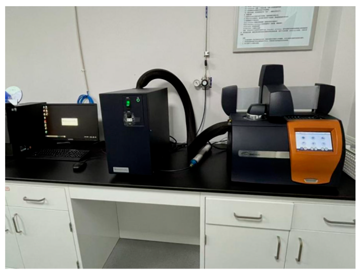
The apparatus employed for thermal property testing is illustrated in Figure 2. The temperature accuracy of the differential scanning calorimeter test results is ±0.025 °C, with enthalpy value precision of ±0.04%. Prior to testing, the apparatus must undergo inspection and calibration. Using an electronic analytical balance, 3–8 mg of the test sample was weighed into a crucible and compacted. The crucibles were numbered sequentially before being placed onto the designated test positions within the DSC sample chamber, with thorough documentation maintained. The corresponding test parameters were configured within the software interface, and the temperature range was set to −10–60 °C. First, the test sample was heated to 60 °C, stabilized for 10 min, then cooled to −10 °C, stabilized for 10 min, and subsequently reheated to 60 °C, where it was held for 10 min. The heating and cooling rate was set at 5 °C/min. Upon completion of the test, data on the heat flow of the composite phase-change material as a function of temperature were obtained. A DSC curve was plotted with heat flow as the vertical axis and temperature as the horizontal axis.
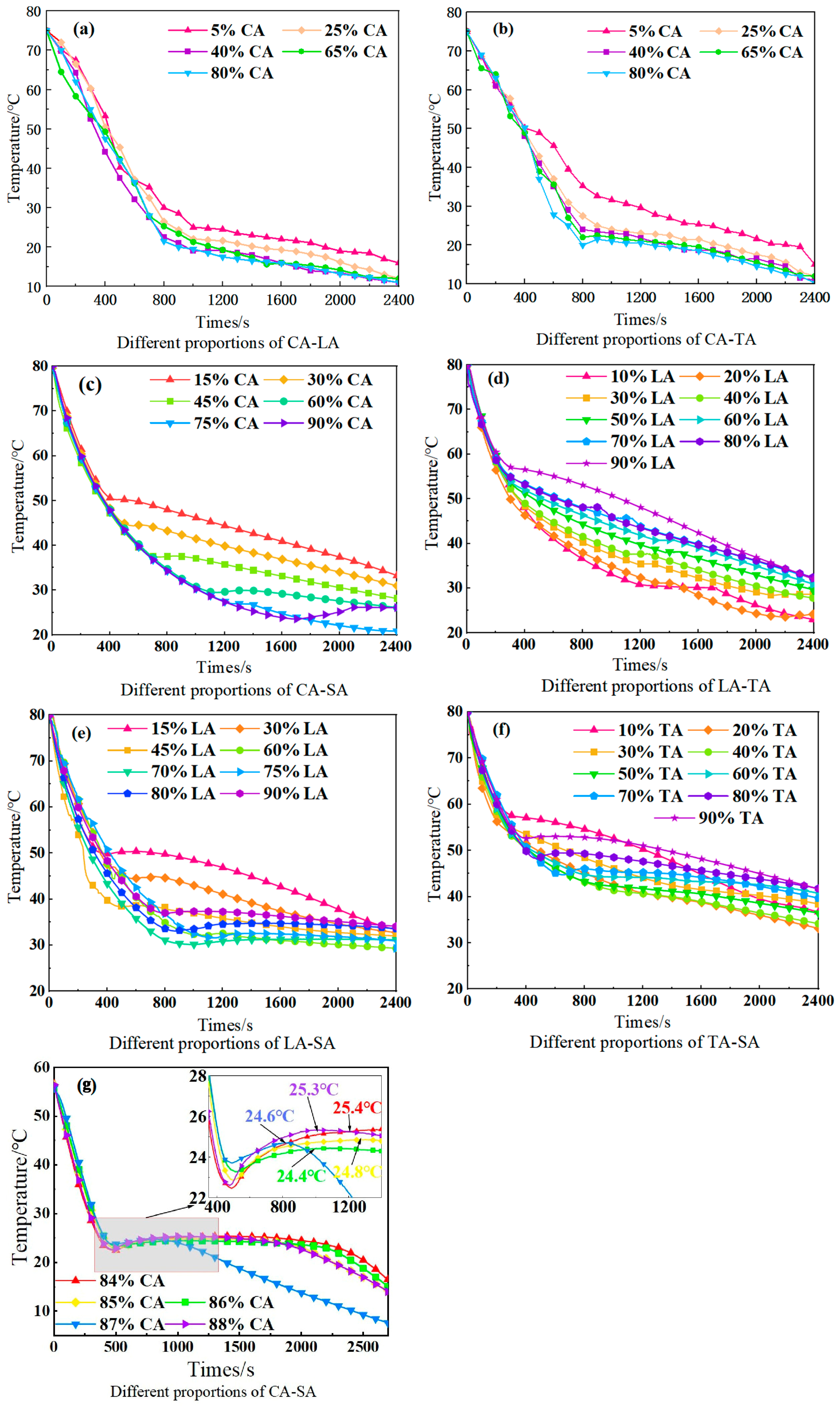
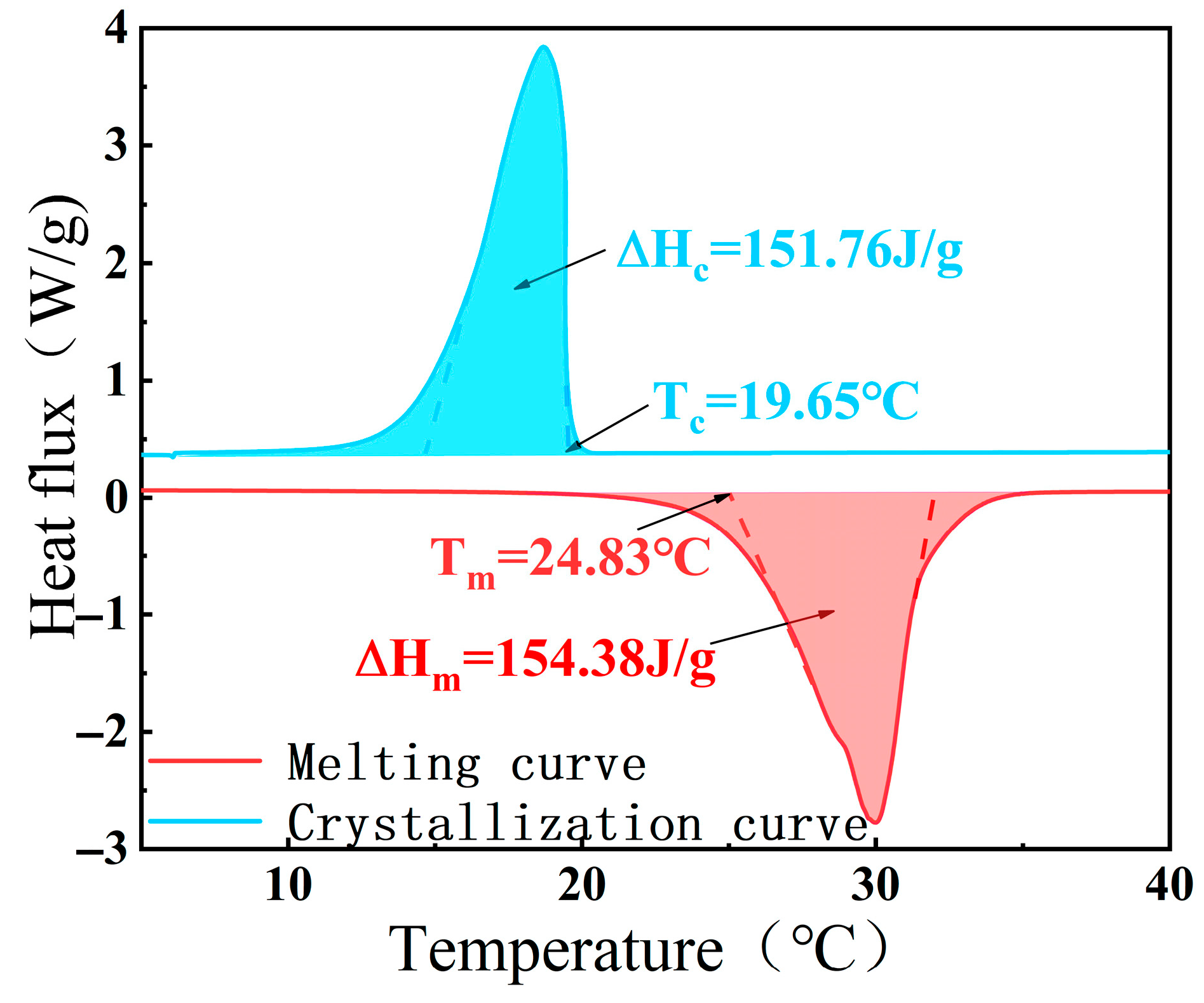
The step cooling test preliminarily determined that the eutectic point of the decanoic acid–stearic acid binary system is around 86% decanoic acid mass fraction, and the crystallization temperature is around 24.4 °C, as shown in Figure 3. The thermal property test further accurately measured the phase-transition temperature to be 24.83 °C and the latent heat of phase transition to be 154.38 J·g−1, as shown in Figure 4. The theoretical and actual thermal performance parameters of other binary systems are shown in Table 7. The deviations between the test results and the theoretical calculation values are small, indicating that the results of the thermophysical property experiments are relatively accurate.
Given that the temperature requirement for indoor thermal environment regulation in buildings is 18–26 °C, it can be seen from the table that the theoretical phase-change temperatures of the CA-TA and CA-SA composite phase-change materials are both within this range, and the theoretical latent heat of phase change of CA-SA is higher than that of CA-TA, indicating a better energy storage effect. Therefore, CA-SA was selected as the composite phase-change material for ceramsite particle adsorption in the subsequent experiments.

2.3. Preparation Process of Composite Phase-Change Ceramsite Aggregate

2.3.1. Adsorption Process of Composite Phase-Change Materials

In the adsorption process, the aggregate treatment method, adsorption temperature, and time are key factors affecting the adsorption of composite phase-change materials by aggregates. The adsorption effect under different factors needs to be measured by the adsorption rate (ωc) (the higher the adsorption rate, the better the effect) to obtain the optimal parameters and optimize the adsorption process. The formula for calculating the adsorption rate is shown in Equation (3).
ω c = m p m d c
where mp is the weight of adsorbed composite phase-change materials (kg), and mdc is the weight of dried ceramsite particles (kg).
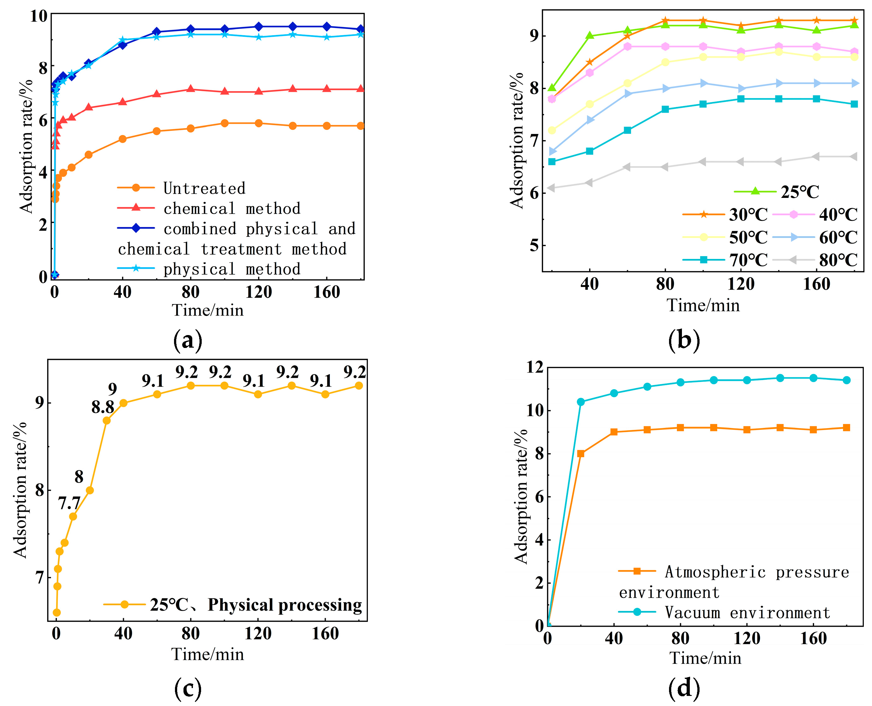
Temperature fluctuations during adsorption (±1 °C) cause changes in the flow properties of phase-change materials, introducing an adsorption rate error of ±0.3%. Humidity fluctuations (±5%RH) cause ceramic particles to absorb moisture, introducing a mass measurement error of ±0.2%. Figure 5a–d show the variation curves of the adsorption rate of ceramsite particles on the composite phase-change materials under different aggregate treatment methods, adsorption temperatures, adsorption times, and adsorption methods, respectively.
The aggregate processing methods include the chemical method, physical method, and combined physical and chemical treatment method. The chemical method involves soaking, neutralizing, washing, and drying; the physical method uses a vibrating screen for treatment; and the combined method first conducts physical vibrating screening, followed by processing according to the chemical process flow. From Figure 5a, it can be seen that under normal temperature and pressure, the adsorption rate of shale ceramsite particles treated by the physical method reaches adsorption equilibrium in 40 min, with an adsorption rate of 9.0%. This method has a simple process, is environmentally friendly and pollution-free, and has high adsorption efficiency.
The adsorption temperature is set in seven temperature zones between 25 °C and 80 °C. Figure 5b shows that as the temperature increases, the adsorption rate of shale ceramsite particles decreases. However, at 25–30 °C, the adsorption rate is higher due to the good melt flowability of phase-change materials. At 30 °C, the adsorption rate is only slightly higher than at 25 °C, and the equilibrium time at 25 °C is shorter. At 80 °C, high temperature causes the pore expansion of ceramsite particles and the reverse movement of the adsorption equilibrium, resulting in a significant decrease in the adsorption rate.
Adsorption time is a key parameter for the large-scale production of composite phase-change aggregates. The experiment set a time gradient between 0.33 and 180 min at 25 °C. The data in Figure 5c shows that the adsorption rate sharply increases and tends to stabilize within 0–30 min, and then fluctuates minimally thereafter.
The experimental results in Figure 5d show that the adsorption rate of aggregates by vacuum adsorption is 1.23 times that of atmospheric pressure adsorption. The equipment built by vacuum adsorption is shown in Figure 6, indicating that the implementation difficulty of a vacuum environment in engineering applications is relatively high, and the increase in adsorption rate compared to an atmospheric pressure environment is limited.
Based on the above experimental data, taking into account the adsorption performance, efficiency, and economy, the optimal process for ceramsite particle adsorption of composite phase-change materials was ultimately determined to be soaking and adsorbing at room temperature and pressure for 30 min after vibrating the screen.

2.3.2. Packaging Process of Composite Phase-Change Materials

This experiment uses decanoic acid–stearic acid composite phase-change material, which is a solid–liquid phase conversion type. After absorbing heat and melting, it is easy to seep out the ceramsite particles, as shown in Figure 7, which affects the phase change performance of the material. The leakage problem needs to be solved through packaging technology.
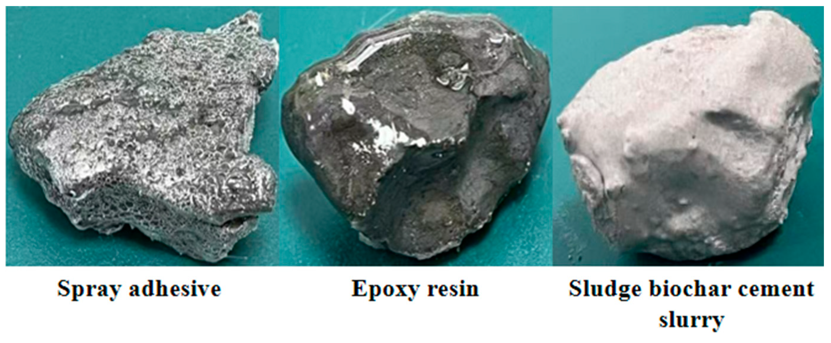
Considering the hydrophobicity of the fatty acid mixture attached to the surface of the ceramsite particles after adsorption, the selected packaging material needs to have a certain viscosity to overcome the difficulties brought by the hydrophobicity of the fatty acid mixture to the packaging process. Secondly, the packaging material needs to consider having a certain strength to resist external load impact and good thermal conductivity to ensure that the composite phase-change material can fully utilize the energy storage effect. Taking into account the integrity of the packaging, mechanical properties, and thermal conductivity requirements, three materials, including epoxy resin, sludge biochar cement slurry, and spray adhesive, were used for packaging process research. The packaging effect is shown in Figure 8. The spray glue used is a multi-purpose spray glue, with a bonding time of less than 0.5 min and a heat resistance temperature of less than 66 °C.
When using sludge biochar cement slurry to encapsulate composite phase-change ceramsite aggregate, the cement water–cement ratio and sludge biochar dosage need to be determined. This study prepared cement slurries with water–cement ratios (W/C) of 0.2, 0.3, 0.4, 0.5, and 0.6, respectively. We immersed the composite phase-change ceramsite aggregate into various proportioned slurries and stirred continuously at a speed of 200 r/min for 5 min to ensure uniform adhesion of the cement slurry on the surface of the aggregate. Then, we placed the treated aggregate on a 400 mesh ultrafine wire mesh for leaching, and the resulting sample morphology is shown in Figure 9. Through comparative analysis, it was found that when the water–cement ratio is too low (W/C = 0.2, 0.3), the viscosity of the cement slurry is high, making it difficult to evenly coat the aggregate, which can easily lead to hollowing or incomplete encapsulation. When the water–cement ratio is high, the flowability of cement slurry is good, and it is easier to evenly wrap the aggregate particles. However, a high water–cement ratio can lead to an increase in porosity after cement hardening, resulting in a decrease in the strength and durability of the encapsulated shell. Moreover, as a poor thermal conductor, an increase in thickness of the cement slurry can reduce thermal conductivity and affect phase transition efficiency. Based on the comprehensive phase change performance, mechanical properties, and encapsulation integrity, a cement slurry with a water–cement ratio of 0.5 was selected for aggregate encapsulation. This ratio ensures the encapsulation weight while controlling the encapsulation layer thickness within 0.5 cm, which is beneficial for improving the overall thermal conductivity of the composite phase-change ceramsite aggregate.
After incorporating sludge biochar into the cement slurry with a water–cement ratio of 0.5 to partially replace cement, the porous structure of biochar exhibited strong water absorption properties. This reduced the shrinkage stresses caused by drying and dispersed stress concentrations within the cement matrix, thereby inhibiting the formation and propagation of microcracks. Furthermore, it enhanced the toughness of the encapsulation layer, ensuring that the structural integrity of the encapsulation layer was maintained during subsequent mixing and pouring processes.
From Figure 10, it can be seen that when the sludge biochar content is 1%, some pores appear on the surface of the encapsulated aggregate, while when the content is 5%, part of the surface of the composite phase-change ceramsite aggregate is exposed to the outside world. These two cannot effectively solve the problem of leakage of phase-change materials under morphological transformation. When the content of sludge biochar is 3%, the thickness of the encapsulated aggregate shell is uniform and dense, and it has good bonding ability with the aggregate. Quantitative data of macroscopic morphology under different sludge biochar dosages were measured by the ImageJ software (Version: 1.54d). The pore ratio of the 3% dosage group (≈5.2%) was much lower than that of the 1% group (≈18.7%), and the surface flatness index (standard deviation 0.12) was significantly better (as shown in Table 8). Meanwhile, it was determined that the compressive strength of the 3% dosage group (28.6 MPa) was 87% higher than that of the 1% group (15.3 MPa), and the impermeability coefficient (1.2 × 10⁻⁹ m/s) was 74% lower than that of the 5% group (4.7 × 10⁻⁹ m/s) (as shown in Table 9), verifying the optimization of the microstructure from the performance level. Therefore, the sludge biochar cement slurry with a content of 3% is the preferred material for “shell making” of composite phase-change ceramsite aggregate. Sludge biochar acts as a nucleation site for cement hydration, promoting the formation of a denser hydration product matrix.

3. Performance of Composite Phase-Change Ceramsite Aggregate

To ensure packaging weight, after completing the encapsulation of composite phase-change ceramsite aggregate, in addition to visually inspecting and confirming the integrity of the encapsulation, a series of tests is also required to evaluate its actual performance. Firstly, the sealing performance of the phase-change material in the liquid state needs to be verified to prevent leakage. Secondly, it is necessary to investigate the anti-damage ability of the encapsulated shell during the concrete mixing process. To this end, this study conducted two key performance tests: evaluating the sealing performance of phase-change materials during the phase transition process through thermal stability tests, and using the mixing and crushing rate test to simulate the mechanical action in actual engineering to examine the anti-damage ability of the encapsulated shell. These tests can systematically evaluate the actual effect of phase-change aggregate encapsulation.

3.1. Thermal Stability

3.1.1. Test Method

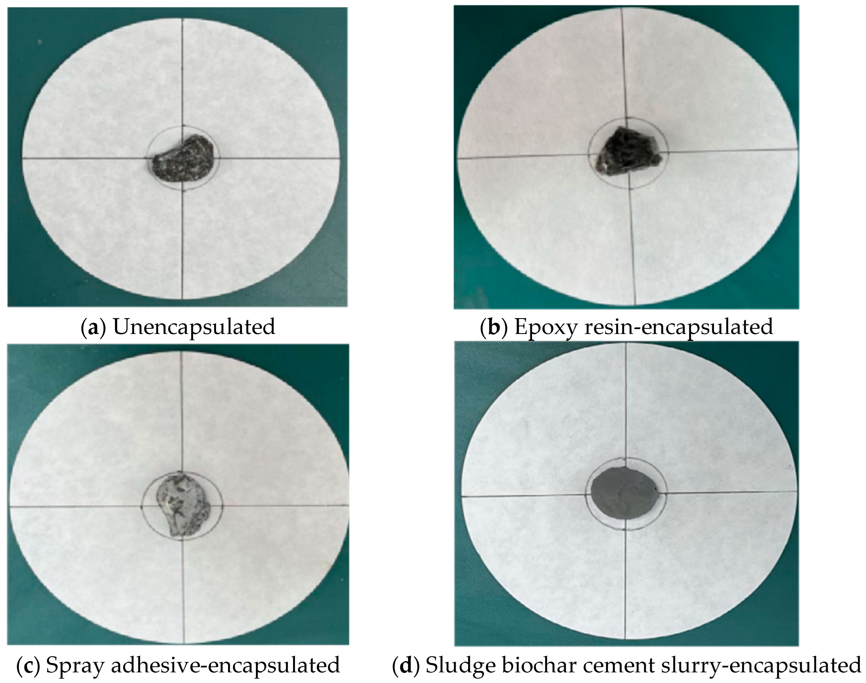
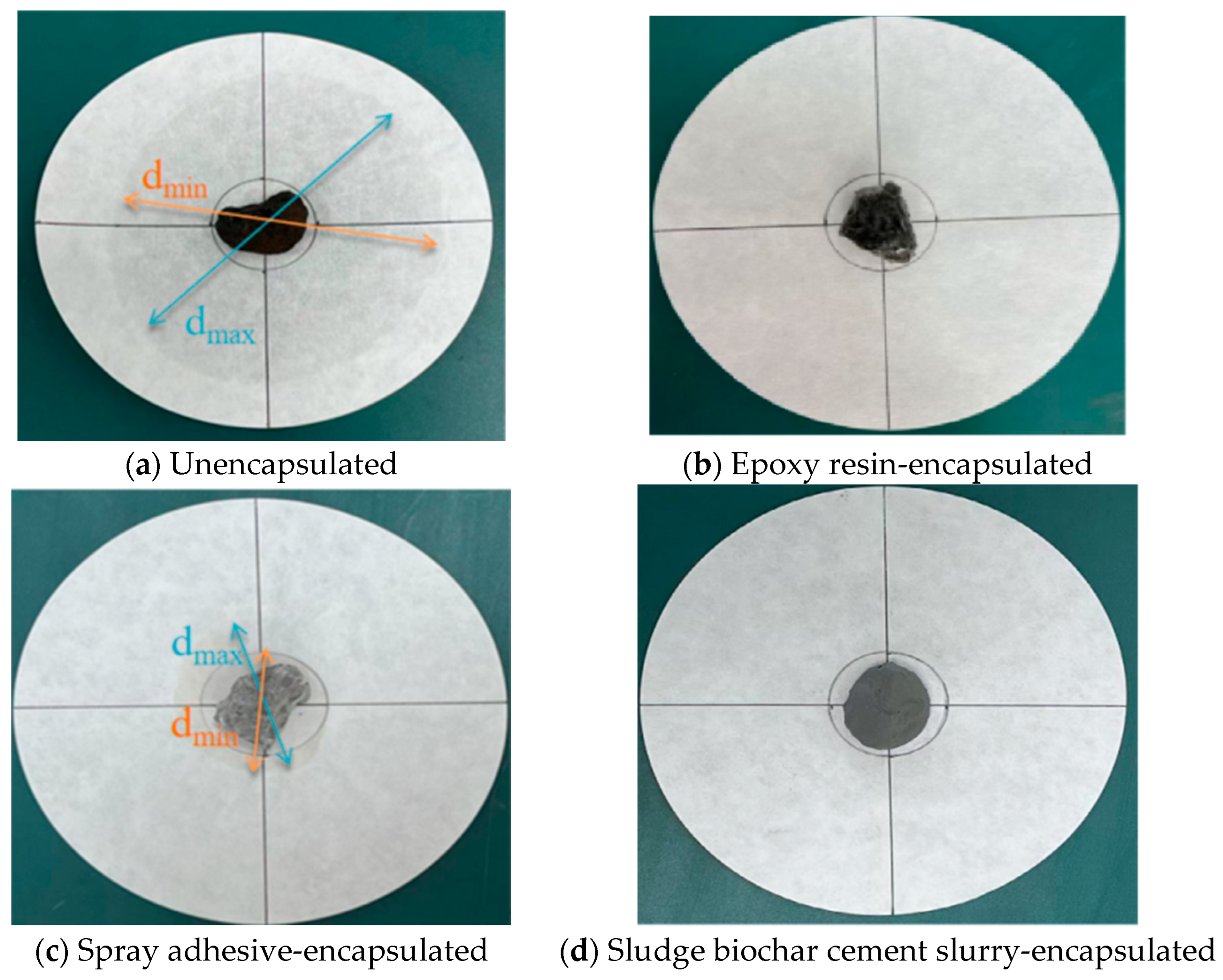
To ensure the reproducibility of the tests and the comparability of data, this study standardized the circular dimensions of filter paper used in thermal stability testing. Qualitative medium-speed filter paper (pore size 80–120 μm) with a diameter of 12.5 cm was employed. The center of the filter paper was determined using a drawing tool, and a circular area with a diameter of 30 mm was drawn with this center as the origin. This dimension is slightly larger than the maximum particle size of the composite phase-change ceramic aggregate (5–20 mm), enabling complete containment of individual aggregates while preventing material from protruding beyond the area during initial placement. We placed the composite phase-change ceramic aggregate sample (individual mass 10–15 g) within the circular area, and then positioned it in a vacuum drying oven (DZF-6050, temperature control accuracy ±1°C) for 12 h of constant heating at 70 °C. Following heating, we observed the leakage extent of the phase-change material on the filter paper. We measured the maximum (dmax) and minimum (dmin) diameters of the leaked liquid using a vernier caliper (accuracy 0.02 mm), calculated the mean diameter (d0), and substituted this into Formula (4) to determine the leakage rate. Compare and judge the obtained exudation percentage φ with the evaluation criteria for the thermal stability of phase-change aggregates shown in Table 10. All the thermal stability tests employed circular filter paper of identical dimensions to ensure direct comparability of the total leakage volumes across the different packaging methods.
φ = d 0 30 30 × 100 %
where d0 is the average of the maximum and minimum diameters dmax and dmin of liquid expansion on filter paper (mm).

3.1.2. Results

Figure 11 and Figure 12a–d show the comparison results of the thermal stability test of the composite phase-change ceramsite aggregates before and after encapsulation, epoxy resin encapsulation, spray coating encapsulation, and sludge biochar cement slurry encapsulation, respectively. It can be seen from the figures that there are no signs of leakage of composite phase-change materials in the composite phase-change ceramsite aggregates encapsulated with epoxy resin encapsulation and sludge biochar cement slurry encapsulation, while the phenomenon of leakage of the composite phase-change materials is more obvious in the composite phase-change ceramsite aggregates encapsulated with spray coating encapsulation and those encapsulated with spray coating, as shown in Figure 12a,c. According to the degree of leakage of the composite phase-change material on the filter paper, measurement and calculation were carried out, and the results are shown in Table 11. It can be seen from the table that the thermal stability of the phase-change aggregates encapsulated by the sludge biochar cement slurry and epoxy resin is very stable, while the composite phase-change aggregates encapsulated by the spray glue are unstable. Therefore, it is not suitable to use spray glue to encapsulate the aggregates.

3.2. Mixing and Crushing Rate

3.2.1. Test Method

To simulate the actual mixing conditions of the project, 50 encapsulated composite phase-change ceramsite aggregates were put into a forced mixer together with 10 kg shale ceramsite aggregates and 6 kg river sand (medium sand, fineness modulus 2.6–2.9, particle size distribution: 0.15–0.315 mm (10%), 0.315–0.63 mm (30%), 0.63–1.25 mm (40%), 1.25–2.5 mm (20%)). The mixing time was set to 240 s. After the mixing was completed, the composite phase-change ceramsite aggregates were separated from other components using a screening method. By visually observing the integrity of each aggregate encapsulation shell, recording the damage situation, and calculating the mixing and crushing rate of the encapsulation shell according to Equation (5), the mechanical damage resistance performance of composite phase-change ceramsite aggregate in an actual construction environment can be evaluated.
P = n p n × 100 %
where P is the crushing rate of phase-change ceramsite aggregate shell (%), np is the quantity of phase-change ceramsite aggregate with broken shell (individual), and n is the total number of phase-change ceramsite aggregate (individual).

3.2.2. Results

According to the experimental results in Table 12, the crushing rates of the composite phase-change ceramsite aggregate encapsulated with epoxy resin, sludge biochar cement slurry, and spray adhesive are 0%, 7%, and 0%, respectively. These three encapsulation materials can effectively maintain the structural integrity of the shell under engineering application conditions.
Although the crushing rate of sludge biochar cement slurry is slightly higher, it has significant advantages in terms of economic and environmental benefits compared to other packaging materials. Taking the packaging of 100 aggregates as an example, the amount of epoxy resin and sludge biochar cement slurry used is about 200 g, with costs of CNY 2.7 (USD 0.38/EUR 0.32) and CNY 0.1 (USD 0.01/EUR 0.01), respectively. Therefore, the economy of using epoxy resin packaging is significantly insufficient. In addition, the curing process of epoxy resin releases volatile organic compounds, is difficult to degrade and recover, has weak adhesion with the cement matrix, and produces toxins during high-temperature decomposition. Its environmental friendliness and structural adaptability are not as good as sludge biochar cement slurry. Therefore, using sludge biochar cement slurry for packaging has more engineering application value.

4. Conclusions

Based on the application scenarios of building envelope structures, the system has completed the screening of phase-change materials for composite phase-change ceramsite aggregates, optimized the preparation process, and studied the performance of aggregates. The following main conclusions have been obtained:
(1) Preliminary screening of composite phase-change materials was conducted through thermodynamic model calculations. After verification through step cooling curves and thermal property experiments, the eutectic ratio of decanoic acid to stearic acid was determined to be 86:14. The phase-transition temperature of this material is 24.83 °C, and the latent heat of phase transition is 154.38 J·g−1. Its phase-transition temperature range is precisely matched with the indoor thermal environment control requirements of buildings.
(2) The adsorption performance of composite phase-change materials is significantly affected by parameters such as adsorption process, time, and phase-change material flowability. Research has shown that ceramsite particles treated by physical vibration screening can reach adsorption equilibrium in 30 min under a normal pressure environment, and have better adsorption efficiency for composite phase-change materials with better fluidity at 25 °C. This process not only meets the requirements of efficient production, but also has the advantages of simple preparation and good economy.
(3) The encapsulation process of sludge biochar cement slurry has outstanding advantages in the preparation of composite phase-change ceramsite aggregate: although the 7% mixing and crushing rate is slightly higher than other encapsulation materials, its encapsulated product has excellent thermal stability, with a production cost of only about CNY 0.1 (USD 0.01/EUR 0.01)/100 pieces, and good compatibility with the cement matrix, which can effectively ensure the overall performance of the composite phase-change material.

Author Contributions

Methodology, D.C.; Validation, J.J.; Formal analysis, J.T.; Writing—original draft, G.Y.; Writing—review & editing, Q.Y.; Project administration, M.L. All authors have read and agreed to the published version of the manuscript.

Funding

This work was supported by Science and Technology Research and Development Program Project of China Railway Group Limited (2023-Major-08).

Data Availability Statement

Data sharing is not applicable. No new data were created or analyzed in this study.

Conflicts of Interest

Author Gui Yu, Qiang Yuan, Min Li were employed by the company National Engineering Research Center for High speed Railway Construction Technolog, Changsha, China, China Railway Group, Beijing China and China Railway Academy of Sciences Group Co., Ltd, Chengdu, China. The remaining authors declare that the research was conducted in the absence of any commercial or financial relationships that could be construed as a potential conflict of interest.

References

  1. Malode, J.S.; Shetti, P.N. Thermal energy storage systems using bio-based phase change materials: A comprehensive review for building energy efficiency. J. Energy Storage 2025, 105, 114709. [Google Scholar] [CrossRef]
  2. Deshmukh, M.; Yadav, M. Optimizing thermal efficiency of building envelopes with sustainable composite materials. Buildings 2025, 15, 230. [Google Scholar] [CrossRef]
  3. Zheng, S.; Qiu, Z.; He, C.; Wang, X.; Wang, X.; Wang, Z.; Zhao, X.; Shittu, S. Research on heat transfer mechanism and performance of a novel adaptive enclosure structure based on micro-channel heat pipe. Energy 2022, 254, 124237. [Google Scholar] [CrossRef]
  4. Bouhezza, A.; Laouer, A.; Ismail, K.A.; Faraji, H.; Khuda, M.A.; Teggar, M.; Lino, F.A.M.; Henríquez, J.R.; Rodríguez, D. Effective techniques for performance improvement of phase change material applications: A review. J. Energy Storage 2025, 105, 114671. [Google Scholar] [CrossRef]
  5. Reddy, J.V.; Ghazali, F.M.; Kumarasamy, S. Advancements in phase change materials for energy-efficient building construction: A comprehensive review. J. Energy Storage 2024, 81, 110494. [Google Scholar] [CrossRef]
  6. Abdel-Mawla, M.A.; Hassan, M.A.; Khalil, A. Phase change materials in thermally activated building systems: A comprehensive review. Int. J. Energy Res. 2022, 46, 11676–11717. [Google Scholar] [CrossRef]
  7. Zhan, H.; Mahyuddin, N.; Sulaiman, R.; Khayatian, F. Phase change material (pcm) integrations into buildings in hot climates with simulation access for energy performance and thermal comfort: A review. Constr. Build. Mater. 2023, 397, 132312. [Google Scholar] [CrossRef]
  8. Yang, H.; Xu, Z.; Cui, H.; Bao, X.; Tang, W.; Sang, G.; Chen, X. Cementitious composites integrated phase change materials for passive buildings: An overview. Constr. Build. Mater. 2022, 361, 129635. [Google Scholar] [CrossRef]
  9. Vega, M.; Marín, P.E.; Ushak, S.; Shire, S. Research trends and gaps in experimental applications of phase change materials integrated in buildings. J. Energy Storage 2024, 75, 109746. [Google Scholar] [CrossRef]
  10. Zhou, D.; Xiao, S.; Xiao, X.; Liu, Y. Preparation, Phase Diagrams and Characterization of Fatty Acids Binary Eutectic Mixtures for Latent Heat Thermal Energy Storage. Separations 2023, 10, 49. [Google Scholar] [CrossRef]
  11. Liang, X.; Fei, H.; Li, Y.; Li, P.; Du, W.; Zhou, J. Structural characteristics and properties of ca-sa-pw/eg adsorbed into porous cement-based for thermal storage. Mater. Today Commun. 2023, 37, 107046. [Google Scholar] [CrossRef]
  12. Yang, Y.; Wu, W.; Fu, S.; Zhang, H. Study of a novel ceramsite-based shape-stabilized composite phase change material (pcm) for energy conservation in buildings. Constr. Build. Mater. 2020, 246, 118479. [Google Scholar] [CrossRef]
  13. Song, M.; Pun, W.M.; Swapnil, D.; Pan, D.; Mao, N. Thermal stability of organic binary pcms for energy storage. Energy Procedia 2017, 142, 3287–3294. [Google Scholar] [CrossRef]
  14. Cao, X.; Zhang, R.; Zhang, N.; Chen, L.; Chen, D.; Li, X. Performance improvement of lauric acid-1-hexadecanol eutectic pHase change material with bio-sourced seashell powder addition for thermal energy storage in buildings. Constr. Build. Mater. 2023, 366, 130223. [Google Scholar] [CrossRef]
  15. Fan, Z.; Zhao, Y.; Ding, Y.; Shi, Y.; Liu, X.; Jiang, D. Fabrication and comprehensive analysis of expanded perlite impregnated with myristic acid-based pHase change materials as composite materials for building thermal management. J. Energy Storage 2022, 55, 105710. [Google Scholar] [CrossRef]
  16. Zhang, D.; Liang, W.; Yang, C. Improving the adsorption of cloud concrete stone porous aggregate to phase change materials by alkali modification. Mater. Lett. 2025, 380, 137717. [Google Scholar] [CrossRef]
  17. Chen, R.; Li, D.; Sheng, N.; Zhu, C. Direct synthesis of porous aluminum nitride foams for enhancing heat transfer and anti-leakage performance of phase change materials. Thermochim. Acta 2024, 734, 179706. [Google Scholar] [CrossRef]
  18. Ghosh, D.; Ghose, J.; Datta, P.; Kumari, P.; Paul, S. Strategies for phase change material application in latent heat thermal energy storage enhancement: Status and prospect. J. Energy Storage 2022, 53, 105179. [Google Scholar] [CrossRef]
  19. Liu, Z.; Teng, R.; Sun, H. Application of pHase change energy storage in buildings: Classification of pHase change materials and packaging methods. Therm. Sci. 2022, 26, 4315–4332. [Google Scholar] [CrossRef]
  20. Huang, Y.; Stonehouse, A.; Abeykoon, C. Encapsulation methods for phase change materials—A critical review. Int. J. Heat Mass Transf. 2023, 200, 123458. [Google Scholar] [CrossRef]
  21. Çolak, B.A. Numerical investigation of thermal energy storage in wavy enclosures with nanoencapsulated phase change materials using deep learning. Energy 2025, 20, 135272. [Google Scholar] [CrossRef]
  22. Tian, Y.; Lai, Y.; Pei, W.; Qin, Z.; Li, H. Study on the physical mechanical properties and freeze-thaw resistance of artificial phase change aggregates. Constr. Build. Mater. 2022, 329, 127225. [Google Scholar] [CrossRef]
Figure 1. Step cooling test site diagram: (a) environmental test chamber and (b) temperature measurement instrument.
Coatings 15 01315 g001
Figure 2. Differential scanning calorimeter.
Coatings 15 01315 g002
Figure 3. Test results of step cooling curve of composite phase-change material.
Coatings 15 01315 g003
Figure 4. Thermal properties test results of CA-SA composite phase-change material.
Coatings 15 01315 g004
Figure 5. Adsorption rates of ceramsite particles using different adsorption processes. (a) Adsorption Rate of Ceramsite Under Different Aggregate Treatment Methods; (b) Adsorption Rate of Ceramsite for Composite Phase-Change Materials Under Different Temperature Environments; (c) Adsorption Rate of Ceramsite for Composite Phase-Change Materials at 25 °C; (d) Adsorption Rate of Ceramsite for Composite Phase-Change Materials Under Different Adsorption Methods.
Coatings 15 01315 g005
Figure 6. Vacuum adsorption device.
Coatings 15 01315 g006
Figure 7. Microscopic magnification of ceramsite particle surface of adsorption composite phase-change material.
Coatings 15 01315 g007
Figure 8. Composite phase-change ceramsite aggregate encapsulated with different materials.
Coatings 15 01315 g008
Figure 9. Composite phase-change ceramsite aggregate encapsulated with cement slurry with different water–cement ratios.
Coatings 15 01315 g009
Figure 10. Composite phase-change ceramsite aggregate after cement slurry encapsulation with different sludge biochar dosages.
Coatings 15 01315 g010
Figure 11. Before the thermal stability test of the composite phase-change ceramsite aggregate.
Coatings 15 01315 g011
Figure 12. After thermal stability testing of composite phase-change ceramsite aggregate.
Coatings 15 01315 g012
Table 1. Main performance indicators of ceramsite particles.
Particle Size (cm)Water Absorption Rate (%)Bulk Density (kg·m−3)Thermal Conductivity (W·m−1K−1)
5–206.57180.23
Table 2. Main performance indicators of phase-change materials.
Phase-Change MaterialsMelting Enthalpy ΔHm (J/g)Phase-Transition Temperature (°C)Molar Mass (g/mol)
Decanoic acid151.8428.83172.26
Lauric acid174.9942.49200.32
Myristic acid186.6852.88228.38
Stearic acid204.2361.58284.48
Table 3. Performance indicators of spray adhesive.
Color
(Hazen)
Epoxy
Equivalent (g/mol)
Bonding
Time (min)
Peel Strength (N/m)Heat Resistance
Temperature (°C)
≤40220~240≤0.5≤5≤66
Table 4. Performance indicators of epoxy resin.
Color
(Hazen)
Epoxy Equivalent (g/mol)Hydrolyzable Chlorine (%)Inorganic Chlorine (g/kg)Softening Point (°C)
≤40220~240≤0.5≤0.0513~22
Table 5. Performance indicators of sludge biochar cement slurry.
Pyrolysis
Temperature (°C)
Moisture Content (%)Specification (Mesh)Bulk Density (cm3/g)Iodine Value (mg/g)
500≤32000.50800
Table 6. Theoretical calculation values of composite phase-change materials.
Composite Phase-Change MaterialsWeight RatioTheoretical Phase-Transition Temperature (°C)Theoretical Latent Heat of Phase Transition (J/g)
CA-LA64.3:35.717.91151.21
CA-TA75.2:24.822.53152.78
CA-SA86.7:13.326.27153.29
LA-TA61.8:39.232.57171.45
LA-SA74.2:25.837.40175.57
TA-SA61.9:38.144.75185.98
Table 7. Comparison of theoretical and actual thermal parameters of six composite phase-change materials.
Composite Phase Change
Materials
Theoretical
Tm (°C)
Actual
Tm (°C)
Actual
Tc (°C)
Relative Deviation
of Tm (%)
CA-LA17.9118.2516.89+1.89
CA-TA22.5323.1121.57+2.57
CA-SA26.2724.8323.21−5.48
LA-TA32.5733.0531.42+1.47
LA-SA37.4038.1236.58+1.92
TA-SA44.7545.3343.67+1.29
Composite phase change
materials
Theoretical
ΔHm (J/g)
Actual
ΔHm (J/g)
Actual
ΔHc (J/g)
Relative deviation
of ΔHm (%)
CA-LA151.21148.63146.92−1.71
CA-TA152.78150.35148.76−1.60
CA-SA153.29154.38152.65+0.71
LA-TA171.45168.92167.34−1.48
LA-SA175.57172.86171.23−1.54
TA-SA185.98183.25181.57−1.47
Table 8. Quantitative analysis of macroscopic morphology of encapsulation layers with different sludge biochar dosages.
Sludge Biochar DosageSurface Pore Area RatioSurface Flatness
(Standard Deviation of Gray Value)
Visual Feature Description
1%18.7%0.35Obvious pores on the surface, distributed dispersedly
3%5.2%0.12Dense and uniform surface, no obvious pore exposure
5%23.4%0.41Partial aggregate exposure, strong pore connectivity
Table 9. Performance test data of encapsulation layers with different sludge biochar dosages.
Sludge Biochar Dosage28 d Compressive Strength (MPa)Impermeability Coefficient (m/s)Phase-Change Material Leakage Rate (%)Thickness of Encapsulation Layer (cm)
1%15.33.6 × 10−98.70.4–0.6
3%28.61.2 × 10−91.30.3–0.5
5%12.54.7 × 10−912.40.2–0.4
Table 10. Evaluation criteria for thermal stability of composite phase-change ceramsite aggregate.
ProjectPercentage of ExudationStability
Very little exudation (considered as no exudation)φ ≤ 10Very stable
Trace10 < φ ≤ 15Stable
A small amount15 < φ ≤ 30Basically stable
Medium quantity30 < φ ≤ 50Instability
A large numberφ > 50Very unstable
Table 11. Calculation results of thermal stability of composite phase.
Phase-Change Ceramsite AggregateNo EncapsulationEpoxy Resin EncapsulationSpray Adhesive PackagingEncapsulation of Sludge, Biochar, Cement Slurry
Maximum diameter (mm)960520
Minimum Diameter (mm)800320
Mean value
(mm)
880420
Percentage of exudation (%)1930400
Stability evaluationVery unstableVery stableInstabilityVery stable
Table 12. Crushing rate of shell after encapsulation of composite phase-change ceramsite aggregate.
Aggregate CategoryEpoxy Resin EncapsulationSpray Adhesive PackagingEncapsulation of Sludge, Biochar, Cement Slurry
Shell breakage rate0%0%7%
Disclaimer/Publisher’s Note: The statements, opinions and data contained in all publications are solely those of the individual author(s) and contributor(s) and not of MDPI and/or the editor(s). MDPI and/or the editor(s) disclaim responsibility for any injury to people or property resulting from any ideas, methods, instructions or products referred to in the content.