Abstract
Under harsh conditions involving high temperatures and severe abrasion, the copper plates of continuous casting crystallizers are highly susceptible to wear failure and thermal cracking. In this study, a Ni60AA transition layer is applied onto the copper plate via laser cladding to enhance the interfacial bonding properties. To further reinforce the coating, TiB2 is incorporated into the nickel-based transition layer, leading to a significant improvement in overall performance. With the addition of 3 wt.% TiB2 and 0.5% Y2O3, the coating microstructure undergoes notable refinement: coarse columnar grains transform into fine equiaxed grains, and the microhardness reaches 1225.3 HV0.1. The coating demonstrates excellent wear resistance, exhibiting a minimal wear depth of 97.09 μm, a low weight loss of 0.0089 g, and a stable friction coefficient of 0.32. By synergistically optimizing the transition layer and incorporating TiB2, this study successfully enhances the surface strength and wear resistance of the crystallizer copper plate, offering a reliable technical approach for extending the service life of continuous casting crystallizers.
1. Introduction
As the critical component of the crystallizer cooling system, the performance of the copper plate directly dictates the internal microstructure and surface quality of the steel billet. However, the plate operates under severe conditions, making it susceptible to failure modes like wear and thermal cracking. Therefore, strengthening the copper plate with a coating is crucial for enhancing the crystallizer’s service life. Electroplated coatings generally exhibit low hardness and are prone to softening under high-temperature conditions, significantly compromising the strength and wear resistance of the crystallizer copper plate [1,2]. While thermal spraying technology offers advantages such as simplicity, high deposition efficiency, and the ability to produce thick coatings, bonding with the substrate is primarily mechanical. Moreover, the process is susceptible to the formation of internal voids, which can adversely affect the performance of the crystallizer copper plate [3]. Laser cladding technology is characterized by its high energy density, rapid cooling rate, low dilution rate, and a narrow heat-affected zone [4,5]. The application of this technique to coat copper plates induces minimal thermal influence on the surface and causes negligible distortion. Moreover, owing to the superior properties of the coating compared to the copper substrate, the treated surface achieves exceptional wear resistance.
The ways in which laser cladding enhances copper substrate performance with functional coatings are being extensively investigated [6,7,8]. Ni1015 alloy coatings and Co-based alloy/TiC/CaF2 composite coatings were successfully fabricated on copper plates [9,10]. A pre-placed powder method was employed to prepare a Ni-based alloy coating on a copper substrate [11]. The thickness of the Ni-WC coating was found to be 0.65 mm, with the average hardness of the reinforced layer reaching 667 HV(0.1); the wear volume was only 0.014 mm3, which corresponds to 1.02% of the wear volume of the copper substrate [12]. The high-temperature wear resistance of Cr13Ni5Si2 composite coatings on a copper substrate was compared between laser cladding and plasma spraying techniques. The results showed that the wear rate of the laser-clad coating was only 21% of the plasma-sprayed coating [13]. A green laser was used to fabricate copper structures on DBC substrates. Absorptivity was enhanced by a graphene oxide coating, which enabled a broader process window for dense specimens [14]. Separately, to mitigate defects such as cracks and pores, a C-Al2O3-Cu composite powder incorporating Ni and Fe was developed. The resulting clad layer exhibited a tensile strength 1.7 times greater than that of the pure copper substrate [15]. This study involved the electrodeposition of Ni-WC composite coatings on pretreated copper substrates to investigate the optimizing effects of nano-sized WC particles on their structure and properties [16]. A simultaneous sevenfold increase in both hardness and wear resistance was achieved by introducing a nickel intermediate layer between molybdenum and copper [17]. Additionally, a Ni–Co composite coating was fabricated on copper, exhibiting an average hardness seven times greater than that of the substrate [18]. The effects of Cu-Cu2AlNiZnAg diamond ratios and ball milling time on coating preparation were investigated [19,20].
A Fe-Co dual-phase coating and a WC-Co composite coating were fabricated on mold copper plates. The incorporation of Ni-WC significantly enhanced microhardness and wear resistance, while gradient designs further improved bonding strength and high-temperature performance [21,22,23]. A Cu-Fe-Al-Si alloyed layer was fabricated on copper, with its phase evolution explained by non-equilibrium solidification during laser processing [24]. The preparation of pure copper components using Blue laser metal deposition achieves high bonding strength and high density (97.9%), along with high hardness of the pure copper coating [25,26,27]. Laser cladding on a copper substrate demonstrated that preheating significantly enhanced the coating’s hardness, wear resistance, and corrosion resistance [28,29,30].
Laser cladding technology can be utilized to enhance the overall surface or perform localized repairs on copper plates. However, research on the application of laser cladding technology for establishing transition layers and strengthening layers on crystallizers is relatively scarce. The wear of the crystallizer copper plates is severe under working conditions, and conventional metal coatings exhibit high sensitivity to cracking and insufficient bonding strength with the substrate, failing to meet the service performance requirements under the harsh conditions of the crystallizer copper plates. Therefore, this study proposes the establishment of a transition layer on crystallizer copper plates to improve bonding performance, followed by the construction of a reinforced coating to enhance the performance of crystallizer copper plates. This study investigates the effects of various preheating temperatures to optimize crack suppression and interfacial bonding strength in Ni60AA transition layers. Subsequently, the effects of TiB2 content variations on the microstructure, grain size, hardness, and wear resistance of Ni60AA coatings are systematically investigated.
2. Experimental Equipment, Materials, and Characterization
2.1. Experimental Equipment and Materials
The laser model is a Nanjing Zhongke Yucheng Laser Technology Co., Ltd. YLR-1000 fiber laser with a maximum power of 1000 W, equipped with an Nanjing Zhongke Yucheng Laser Technology Co., Ltd. RC52 laser head. The standard focal length is 150 mm, the focused focal length is 300 mm, the working distance is 16 mm, and the spot diameter is 0.6 mm. The water chiller circulates cooling water to the external optical path system, and the powder feeder is an RC-PGF-D-2 dual-hopper negative-pressure powder feeding device. The complete laser-directed energy deposition (L-DED) system is integrated into a vertical machining center, as illustrated in Figure 1. The system exhibits high transmission accuracy, meeting the precision requirements for laser-directed energy deposition processes. To prevent high-temperature oxidation reactions of metal powders in the deposition zone, argon gas is employed as both the powder carrier gas and shielding gas. The process flow of laser-directed energy deposition (L-DED) is illustrated in Figure 2.
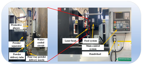
Figure 1.
Laser Cladding Equipment.
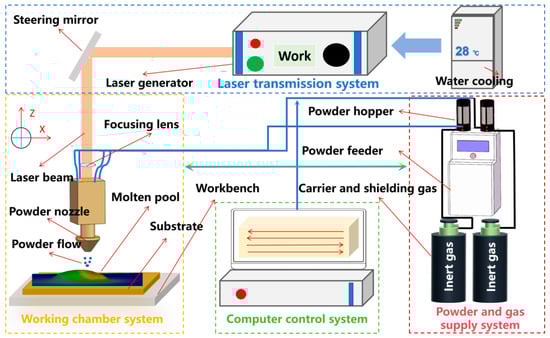
Figure 2.
The Process Flow of Laser Cladding.
The experimental substrates in this study are Cu-Cr-Zr alloys for continuous casting crystallizers, with a chemical composition substantially consistent with the casting crystallizer. The primary constituents of the alloy are Cu, Cr, and Zr, Cu: 99.25%, Cr: 0.65%, Zr: 0.1%.
To address the problems of nickel-based coating, such as low hardness and poor wear resistance, Ni60AA powder is utilized as the base powder, with its composition detailed in Table 1 [31]. An appropriate amount of TiB2 ceramic powder is added as a reinforcing phase to enhance the properties of the coating. The physical properties of the TiB2 particles are presented in Table 2 [31]

Table 1.
Composition of Ni60AA powder.
Table 2.
Physical Properties of TiB2 Particles.
2.2. Experimental Methods and Characterization
An orthogonal experimental design is employed in this study to optimize the process parameters for fabricating a single-pass nickel-based transition coating. The optimal parameter range for the nickel-based transition layer on the copper substrate is determined as follows: laser power of 700–1000 W, scanning speed of 320–520 mm/min, and powder feed rate of 0.4–0.9 r/min. Within this range, a three-factor, six-level orthogonal experiment is designed, as shown in Table 3. The entropy weight-TOPSIS method is applied to identify the optimal process parameter combination for the nickel-based transition layer on the crystallizer surface. The optimal parameters are identified as a laser power of 850 W, a scanning speed of 480 mm/min, and a powder feed rate of 0.5 r/min.
Table 3.
Factor levels and types.
To investigate the influence of TiB2 content in composite powders on the microstructure and properties of the coating, four experimental groups with varying TiB2 contents are designed. The addition of the ceramic reinforcement phase TiB2 is found to result in a high susceptibility to cracking in the coatings. Incorporating an appropriate amount (0.5%–1.5%) of rare earth compounds can promote grain refinement and inhibit crack initiation and propagation. However, excessive addition of rare earth compounds may increase the risk of cracking. Therefore, 0.5% Y2O3 is added to the composite powders in this experiment to refine the microstructure of the deposited layers. The compositions of the four experimental groups are shown in Table 4.
Table 4.
Powder Composition.
The specimen testing procedure is conducted as follows: The specimens are mounted, ground, and polished, followed by etching with aqua regia for 25–30 s. The etched samples are then cleaned in an ultrasonic cleaning device. The microstructure of the coating is analyzed using a CIQTEK SEM3100 Scanning Electron Microscope from Guoyi Quantum (SEM). An Olympus’ DSX1000 Ultra Deep Well Microscope is employed for further examination. The phase composition of the deposited layers is determined using a Rigaku UltimaIV X-ray diffractometer from Aolong Ray Instrument Co., Ltd(XRD). The hardness of the deposited layers is measured using an Laizhou Huayu Zhongxin Testing Instrument Co., Ltd. HVS-1000 Vickers microhardness tester. The measurements are conducted at the interface between the substrate and the coating, extending towards the upper surface and into the substrate. A load of 100 g is applied for a duration of 15 s. Hardness measurements are taken starting from the deposited surface down to the interface, with data points collected at intervals of 0.1–0.2 mm in the vertical direction. For each data point, five measurements are taken horizontally, and the average value is calculated for each set of data.
The friction and wear tests are conducted using an The MM-10000A reciprocating wear testing machine from Jinan Blue Wave Testing Equipment Co., Ltd.. Friction and wear test conditions: A tungsten carbide ball with a diameter of 6 mm is used as the counter ball. The test is conducted under a load of 100 N, a sliding speed of 30 mm/s, an amplitude of 5 mm, a frequency of 1 Hz, and a test duration of 30 min. After the test, the specimens are cleaned using an ultrasonic cleaner, and their weights are measured to calculate the wear loss. The morphology and depth of the wear tracks are observed using an ultra-depth microscope, and the wear morphology of the deposited layer surface is analyzed using a scanning electron microscope (SEM).
3. Results and Discussion
3.1. The Effect of Substrate Preheating on the Transition Coating
Fine pores and cracks within the deposited layer are difficult to eliminate solely through process parameter optimization. Substrate preheating is shown to effectively reduce the likelihood of cracking during the formation of the nickel-based transition layer on chromium-zirconium-copper alloys. The metallographic cross-sections of layers deposited with substrate preheating at 200 °C, 300 °C, and 400 °C are presented in Figure 3. As the preheating temperature increases, the temperature gradient between the deposited layer and the substrate is significantly reduced, which lowers residual stress and mitigates stress concentration within the layer, thereby suppressing crack formation. In addition, preheating markedly decreases the generation of pores and cracks, with porosity exhibiting a declining trend as temperature rises. Compared to preheating at 200 °C and 300 °C, the layer prepared at 400 °C demonstrates superior interfacial bonding quality. At this temperature, a dilution rate of 46% and an aspect ratio of 5 are achieved, meeting the requirements for substrate-coating interfacial integrity while preventing potential coating collapse.
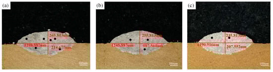
Figure 3.
The metallographic section diagram of the preheated coating. (a) Preheat to 200 °C; (b) Preheat to 300 °C; and (c) Preheat to 400 °C.
3.2. Macroscopic and Microscopic Morphology
3.2.1. Macroscopic Morphology
As can be seen from Figure 4, with the increase of TiB2 content, the surface of the coating is relatively flat, the contour of the molten pool is clear, and no obvious collapse or irregular accumulation is seen, it shows that the addition of 1%–3% TiB2 does not have a significant negative effect on the stability of the cladding process. As depicted in Figure 4a, TiB2 content is 1 wt. %, the edge of the deposition layer is slightly rough, which may be related to the powder distribution or energy input in the early stage of cladding. As depicted in Figure 4b, when TiB2 content increased to 2 wt. %, the edge of the deposition layer is clearer, the formability is improved, and the solidification trace of the molten pool on the surface is uniform, indicating that an appropriate amount of TiB2 can improve the fluidity of the molten pool and promote the uniformity of the microstructure. At TiB2 content of 3 wt. % as shown in Figure 4c, although the overall morphology is still relatively flat, there are a few slight ablation or splash marks at the edges, which may be related to the uneven energy absorption and the local fluctuation of heat input caused by the high content of ceramic reinforcement.
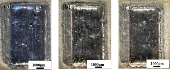
Figure 4.
Macroscopic morphology of coatings with different TiB2 contents. (a) Ni60AA + 1 wt.%TiB2; (b) Ni60AA + 2 wt.%TiB2; (c) Ni60AA + 3 wt.%TiB2.
Figure 5 illustrates crack defects within the coating with 5 wt.% TiB2 addition. When the TiB2 content increases to 5 wt.%, the coating surface exhibits extensive crack networks and porosity. The excessive TiB2 content introduces brittleness to the coating, promoting crack initiation during the deposition process. Furthermore, the accumulation of hard TiB2 phases disrupts the continuity of the molten pool, significantly reducing its fluidity. This hindered flow impedes the escape of entrapped gases, leading to the formation of gas pores. Consequently, the composite powder containing 5 wt.% TiB2 is excluded from subsequent microstructural characterization and mechanical property evaluations due to these severe structural defects.
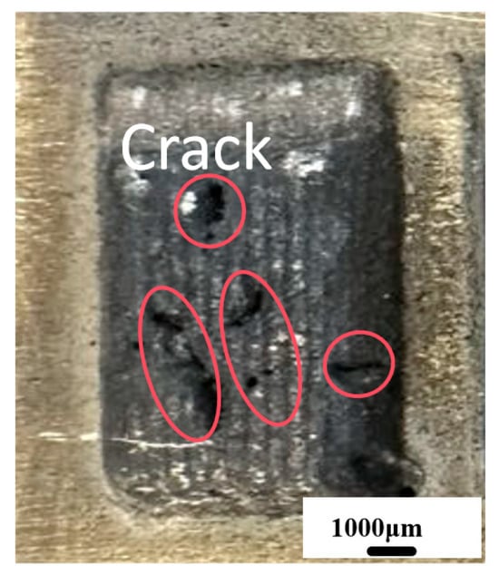
Figure 5.
Crack defects of coating.
3.2.2. Microscopic Morphology
TiB2, as a hard ceramic material, significantly enhances the hardness and wear resistance of the coating when added. However, it also leads to poorer fluidity of the molten pool and uneven cooling rates, thereby increasing the formation of pores. Although increased porosity is often considered a defect, the limitations of the laser cladding process make the formation of pores inevitable. Therefore, a slight amount of porosity is acceptable as long as it does not adversely affect the primary properties of the coating, as shown in Figure 6. As shown in Figure 6a, when the TiB2 content is 0 wt.%, the metallographic morphology of the coating is well-formed, with only a small number of fine pores present. Furthermore, the linear expansion coefficient of Ni60AA powder is closest to that of chromium-zirconium copper alloy, enabling it to form a strong metallurgical bond with the mold copper plate. As shown in Figure 6b, when the TiB2 content in the composite powder is 1 wt.%, only a minimal amount of unmelted TiB2 particles is observed in the coating. This is primarily due to the fact that the proportion of TiB2 in the composite powder is significantly lower than that of the Ni-based powder, resulting in an extremely limited number of unmelted TiB2 particles in the coating. Additionally, some TiB2 particles reacted with the Ni-based powder, forming new hard phases.
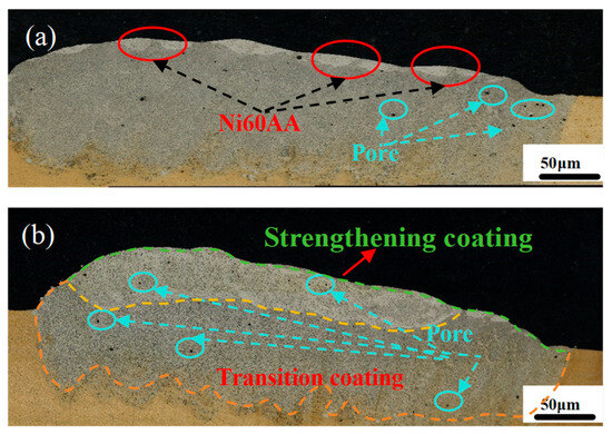
Figure 6.
Contains 0 wt.% TiB2 and 1 wt.% TiB2 coating. (a) 0 wt.% TiB2; (b) 1 wt. % TiB2.
As shown in Figure 7, it contains 2 wt.% TiB2 and 3 wt.% TiB2 coating microstructures. As illustrated in Figure 7a, when the TiB2 content is increased to 2 wt.%, the amount of TiB2 in the reinforced coating further increases, with unmelted TiB2 particles uniformly distributed in the molten pool. The reinforced coating exhibits a well-formed morphology, with significantly improved hardness and wear resistance. Only a few tiny pores with diameters around a few micrometers are present, and no obvious pores or crack defects are observed. As shown in Figure 7b, it can be observed that when the TiB2 content is increased to 3 wt.%, the amount of TiB2 in the reinforced coating further increases, with unmelted TiB2 particles uniformly distributed in the molten pool. The reinforced coating exhibits a well-formed morphology, with even greater improvements in hardness and wear resistance, and no significant pores or crack defects are present.
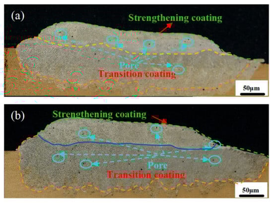
Figure 7.
Coating containing 2 wt.% and 3 wt.% TiB2 particles. (a) 2 wt. % TiB2; (b) 3 wt.% TiB2.
3.3. Microstructure of TiB2 Reinforced Coating
3.3.1. Phase Composition
The content of TiB2 is 1 wt. %, 2 wt. %, 3 wt. As shown in Figure 8, the phases of the coating are mainly γ-Ni, TiB2, NI2B, and a small amount of TiB, CR2B, Ni2Si, etc. The results show that some TiB2 particles react with Ni-based alloy elements to form new hard phases during laser melting. Laser focusing on the surface of the substrate will produce extremely high temperatures, resulting in partial or total melting of TiB2 particles and reacting with elements such as Ni and Cr. The partial decomposition of TiB2 yields TiB and B, which are soluble in Ni-based liquids. At high temperatures, Ti and B elements diffuse with Ni and Cr atoms to form new hard phases. During the cooling process, these elements precipitate and form crystal nuclei, and finally form new hard phases with high hardness and strength, which enhance the coating performance. In the XRD patterns of the three samples, the diffraction peaks are basically the same, but the peak intensities are different. With the increase in the proportion of TiB2, the diffraction peak is gradually weakened, indicating that the amount of decomposition of TiB2 is reduced. When the proportion of TiB2 is small, the melting of Ni is higher and the fluidity of the molten pool is stronger, which is conducive to the diffusion of B atoms and promotes the reciprocating chemical reaction between TiB2 and TiB, B.
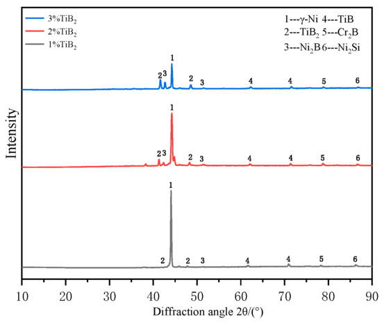
Figure 8.
XRD patterns of strengthening coatings with different TiB2 contents.
3.3.2. Strengthening Coating Grain Size
To investigate the influence of TiB2 addition on the grain structure of Ni60AA reinforced coatings, electron backscatter diffraction (EBSD) analysis is performed, as shown in Figure 9. The results reveal that the grain size and morphology undergo significant changes with increasing TiB2 content. As shown in Figure 9a, in the absence of TiB2, the top region of the coating is dominated by coarse columnar grains with a pronounced preferential orientation, indicating a strong temperature gradient during solidification and a cooling rate insufficient to suppress columnar grain growth. As displayed in Figure 9b, when TiB2 content is increased to 1 wt.%, the grain size of the coating begins to decrease, and some columnar grains are refined to form a certain number of equiaxed grain zones. As depicted in Figure 9c, with an increase to 2 wt.%, the grains are further refined, the columnar grains are largely broken, the proportion of equiaxed grains is significantly increased, and the grain boundary distribution tends to be uniform. As shown in Figure 9d, the TiB2 content is 3 wt.%, the grains at the top of the coating are almost completely transformed into fine equiaxed grains with uniform distribution, the grain size is significantly reduced, and the density of the microstructure is improved. The evolution of microstructure shows that TiB2 particles play the role of grain refiner in the cladding process. As a heterogeneous nucleation core, TiB2 improves the nucleation rate, and its high melting point and stability help to hinder grain growth during solidification, inhibiting the preferential growth of columnar crystals, and thus promoting the formation of equiaxed grains.
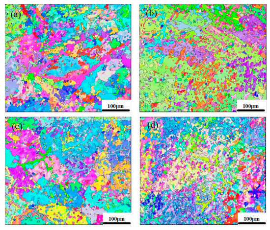
Figure 9.
Strengthening coating under different TiB2 content. (a) 0 wt.% TiB2; (b) 1 wt.% TiB2; (c) 2 wt.% TiB2; (d) 3 wt.% TiB2.
EBSD analysis is carried out on the nickel-based strengthened coating with the addition of 3% TiB2 to explore the grain size of the upper, middle, and joint of the coating. The grain sizes at the bottom, middle, and top of the coating are shown in Figure 10. Figure 10a shows that the grains in the bonding zone of the coating are primarily coarse columnar grains and columnar dendrites. As shown in Figure 10b, the middle region of the coating exhibits a gradual refinement of columnar grains, alongside a microstructural transition from medium columnar dendrites to fine columnar dendrites and larger equiaxed grains. Figure 10c shows that the upper part of the coating consists mainly of very fine dendrites and smaller equiaxed grains. At the bottom of the molten pool, where it contacts the cold substrate, the temperature gradient is extremely high, and crystals undergo epitaxial growth using the substrate as a base, resulting in the formation of coarse columnar grains. As the solidification front advances toward the middle and upper regions of the molten pool, the temperature gradient decreases while the cooling rate remains high, leading to a significant increase in constitutional supercooling. At this stage, TiB2 particles act as highly effective heterogeneous nucleation sites, promoting the nucleation of a large number of equiaxed grains. Particularly in the upper part of the molten pool, where the temperature gradient is minimal and the cooling rate is the highest, the nucleation effect of TiB2, combined with the extremely high cooling rate, suppresses grain growth, ultimately resulting in the formation of the finest equiaxed grain structure. This proves that 3% TiB2 can effectively refine the grain size and improve the mechanical properties.
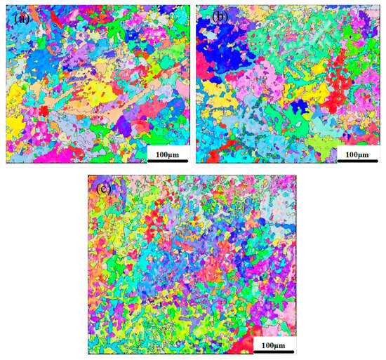
Figure 10.
Coating with 3% TiB2 addition. (a) Coating joint; (b) middle of coating; and (c) top of coating.
3.4. Mechanical Properties
3.4.1. Mechanism of Hardness and Wear Improvement
The relationship between grain refinement and mechanical properties can be quantitatively described. As shown in Equation (1), the Hall-Petch equation indicates that a reduction in grain size leads to an increase in the material’s yield strength. Given the intrinsic correlation between hardness and strength, smaller grain dimensions similarly contribute to increased hardness. As illustrated in Figure 11, this strengthening mechanism arises from the proliferation of grain boundaries per unit volume during grain refinement. These boundaries exhibit disordered atomic arrangements, elevated free energy, and heightened dislocation density. When dislocations propagate through the lattice and encounter grain boundaries, their motion is impeded by interactions with boundary dislocations, thereby elevating the material’s resistance to plastic deformation and ultimately improving hardness. Furthermore, the Archard wear model, as shown in Equation (2), predicts that enhanced hardness directly correlates with reduced wear volume, emphasizing the critical role of grain refinement in optimizing wear resistance.
where σs, d, K, σ0, W, F, M, S, and H are the yield strength of the material, the grain size, the coefficient related to crystal structure (reflecting the influence of grain boundaries on strength), the constant associated with crystal structure and dislocation density, the wear volume, the normal load, the wear coefficient, the sliding distance, and the material hardness, respectively.
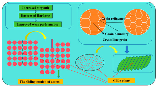
Figure 11.
Mechanism of hardness and wear improvement.
3.4.2. Hardness and Wear
As shown in Figure 12, the microhardness measurement results of the reinforced coating with different TiB2 additions are presented. With the increase in TiB2 content, the microhardness of the TiB2-reinforced nickel-based coatings gradually increases, and the rate of increase becomes more pronounced. The average microhardness values of the transition layer and the nickel-based reinforced coating are 651.8 HV0.1, 729.96 HV0.1, 838.94 HV0.1, and 1225.3 HV0.1, respectively. Compared to the substrate (with an average microhardness of 135.1 HV0.1), these values represent increases of approximately 4.82 times, 5.4 times, 6.21 times, and 9.1 times, respectively. TiB2 forms uniformly distributed hard dispersed particles in the nickel matrix. These second-phase particles generate strong hindering effects through the movement of pinned dislocations, significantly enhancing the coating’s resistance to plastic deformation. As the TiB2 content increases, the density of dispersed particles per unit volume increases, and the strengthening effect exhibits nonlinear enhancement.
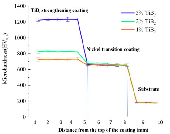
Figure 12.
The microhardness distribution of the coatings with different TiB2 additions.
Given that the primary failure mode of copper plates is wear failure, the focus is primarily on hardness and wear performance, without considering tensile properties. The wear morphology and three-dimensional topography of the substrate and reinforced coatings with different TiB2 contents are shown in Figure 13. Figure 13a depicts the wear morphology of the substrate, with a wear scar width of 3231.78 μm and a depth of 213.09 μm. The wear morphology of the 1 wt.% TiB2 coating is shown in Figure 13b, with a wear scar width of 3011.55 μm and a depth of 155.12 μm. The wear morphology of the 2 wt.% TiB2 coating is illustrated in Figure 13c, with a wear scar width of 2511.55 μm and a depth of 123.66 μm. As shown in Figure 13d, the wear morphology of the 3 wt.% TiB2 coating, with a wear scar width of 2331.55 μm and a depth of 97.09 μm. Compared to the substrate, the 3 wt.% TiB2 coating exhibits a 27% reduction in wear scar depth and a 54% reduction in width. These results indicate that the addition of TiB2 not only significantly improves the surface hardness of the nickel-based alloy but also enhances its wear resistance.
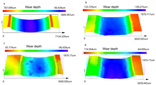
Figure 13.
Wear morphology. (a) Substrate; (b) 1 wt.% TiB2; (c) 2 wt.% TiB2; (d) 3 wt.% TiB2.
As shown in Figure 14, the friction coefficient curve and wear mass of the strengthened coating versus the substrate are presented, where both the friction coefficient and wear mass represent the average values obtained from three measurements. In addition, the friction coefficient reported in this study is determined using the apparent contact area.
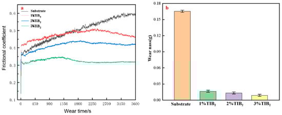
Figure 14.
Friction coefficient and wear mass. (a) Coefficient of friction; (b) wear mass.
As shown in Figure 14a, when silicon carbide is used as the grinding medium under a load of 100 N for 3600 s of reciprocating friction, the friction coefficient of the Cr-Zr-Cu substrate continuously increases and eventually stabilizes with fluctuations. The friction coefficient rises due to the generation of wear debris in the initial stage of the test, and the cumulative effect causes a rapid increase in the friction coefficient. The friction coefficient trends of Ni60AA reinforced coatings with different TiB2 contents are similar, but their specific behaviors differ. For the 1 wt.% TiB2 coating, the friction coefficient rapidly increases to 0.44 within the first 200 s, followed by a transition phase from 200 to 1500 s, during which the friction coefficient gradually rises to 0.5 and then decreases to 0.42. It subsequently stabilizes at around 0.42. The friction coefficient trends of the 2 wt.% and 3 wt.% TiB2 coatings are similar, entering a stable phase after 1500 s, with friction coefficients stabilizing at approximately 0.40 and 0.32, respectively. This indicates that as the TiB2 content increases, the friction coefficient gradually decreases, demonstrating that the addition of TiB2 significantly improves the friction stability and wear resistance of the coatings. The wear loss, as shown in Figure 14b, is 0.0165 g, 0.0133 g, and 0.0089 g for the 1 wt.%, 2 wt.%, and 3 wt.% TiB2 coatings, respectively, while the wear loss of the Cr-Zr-Cu substrate is 0.1654 g. The wear losses of the reinforced coatings are reduced by 0.1489 g, 0.1521 g, and 0.1565 g, respectively. Based on these results, the 3 wt.% TiB2 coating exhibits the best wear resistance and microhardness, with a well-formed coating structure, meeting the wear resistance requirements for crystallizers.
The observed reduction and delayed evolution of the friction coefficient with increasing TiB2 content are attributed to both physical strengthening effects and tribological mechanisms. The addition of TiB2 leads to a refined microstructure and the formation of hard ceramic reinforcement particles that effectively bear the applied load and reduce the real contact area between the counterface and the coating. This decreases the severity of adhesive junction formation and slows down the generation of wear debris, thereby stabilizing the friction behavior at a lower level. In contrast, the substrate without TiB2 shows a rapid rise in friction due to severe plastic deformation and the accumulation of oxides and loose wear debris, which promotes a transition from mild to abrasive wear at an early stage. With increasing TiB2 content, the friction coefficient reaches its initial peak earlier, which implies that the reinforced surface rapidly forms a stable tribo-film composed of compacted wear particles and oxides. This tribo-film acts as a solid lubricant layer, preventing direct asperity contact and suppressing friction fluctuations. In low-TiB2 or unreinforced samples, the formation of such a film is delayed or remains unstable, resulting in prolonged friction fluctuations and a higher steady-state value.
4. Conclusions
The crystallizer is a critical component ensuring the stable operation of the continuous casting process. With ongoing advancements in technology and materials, higher requirements have been imposed on the surface performance of the crystallizer to ensure its reliability and safety under various operating conditions. This study focuses on the copper plate of the crystallizer, conducting an in-depth analysis of the various loads it endures during the continuous casting process and investigating the requirements for surface enhancement and service performance, proposing a laser cladding technology process for fabricating a functionally graded coating to reinforce the crystallizer. This approach aims to achieve surface re-enhancement through the application of a graded coating via laser cladding technology. The main research conclusions are as follows:
- (1)
- Through microstructural analysis of the coating, the optimal preheating temperature was determined to be 400 °C, revealing the mechanism by which preheating suppresses porosity and cracking.
- (2)
- Laser cladding technology process experiments were conducted with different Ni60AA-TiB2 powder ratios, and a comparative analysis was performed to evaluate the effects of varying TiB2 content on the morphology and microstructure of the functionally graded coating.
- (3)
- When the TiB2 content was 3 wt.%, significant grain refinement was observed, with coarse columnar grains transforming into fine equiaxed grains. The wear depth was measured at 97.09 µm, the hardness reached 1225.3 HV0.1, the wear mass loss was only 0.0089 g, and the friction coefficient remained stable at 0.32.
Although the addition of TiB2 ceramic powder effectively enhances the hardness and wear resistance of the reinforced coating, the density difference between TiB2 and the Ni-based powder results in an uneven distribution of TiB2 within the coating, leading to the presence of minor porosity. To address this problem, future research will focus on incorporating auxiliary devices for stirring or vibrating the molten pool to achieve a more uniform distribution of TiB2 particles within the coating.
Author Contributions
D.L.: Methodology, Writing, Simulation, Review and Editing. W.L.: Conceptualization, Project administration, Supervision, Visualization, Funding acquisition, Review and Editing. X.J.: Funding acquisition, Review and Editing A.L.: Conceptualization, Methodology, Resources, Supervision. All authors have read and agreed to the published version of the manuscript.
Funding
This research was funded by the 2016 Green Manufacturing System Integration Project of Ministry of Industry and Information Technology of China under Grant 201675514, Research on the Theory and Method of Quality Intelligent Control in the Remanufacturing Process of Waste Mechanical and Electrical Products under Grant 51305279, the Program for the Top Young Innovative Talents of Liaoning Revitalization Talent Program under Grant XLYC1807211 and XLYC1802038, the Key Program of the Educational Department of Liaoning Province (LJKZZ2022023), the Unveiling and Commanding Program of Liaoning Province (2022JH1/10800061), Liaoning Provincial Department of Education Project under Grant LJKQZ20222299, the Shenyang Natural Science Foundation (23-503-6-01), and Program for the Top Young and Middle-aged Innovative Talents of Shenyang under Grant RC190148. No potential conflicts of interest were reported by the authors.
Institutional Review Board Statement
Not applicable.
Informed Consent Statement
Not applicable.
Data Availability Statement
Data will be made available on request.
Conflicts of Interest
The authors declare that they have no known competing financial interests or personal relationships that could have appeared to influence the work reported in this paper.
References
- Srnec, N.J.; Lanzutti, A.; Benasciutti, D.; De Bona, F.; Moro, L.; De Luca, A. On the damage mechanisms in a continuous casting mold: After-service material characterization and finite element simulation. Eng. Fail. Anal. 2018, 94, 480–492. [Google Scholar] [CrossRef]
- Gaiser, P.; Klingler, M.; Wilde, J. The influence of strain hardening of copper on the crack path in Cu/Al2O3/Cu direct bonded copper substrates. Int. J. Fatigue 2020, 140, 105821. [Google Scholar] [CrossRef]
- Pingale, A.D.; Owhal, A.; Katarkar, A.S.; Belgamwar, S.U.; Rathore, J.S. Recent researches on Cu-Ni alloy matrix composites through electrodeposition and powder metallurgy methods: A review. Mater. Today Proc. 2021, 47, 3301–3308. [Google Scholar] [CrossRef]
- Liu, A.; Jiang, X.; Song, B.; Chen, K.; Xu, X.; Yang, G.; Liu, W. A multi-objective optimization method of directed energy deposition manufacturing process considering carbon emission. J. Clean. Prod. 2024, 452, 142144. [Google Scholar] [CrossRef]
- Oliveira, J.; Correia, V.; Castro, H.; Martins, P.; Lanceros-Mendez, S. Polymer-based smart materials by printing technologies: Improving application and integration. Addit. Manuf. 2018, 21, 269–283. [Google Scholar] [CrossRef]
- Han, Y.J.; Zhou, C.Y.; Li, H.; Zhang, J.J. Green precision manufacturing of ultrathin copper foil leadframes by ultraviolet nanosecond pulsed laser microdrilling. Sustain. Mater. Technol. 2025, 45, e01553. [Google Scholar] [CrossRef]
- Mao, Z.; Zhang, D.Z.; Jiang, J.; Fu, G.; Zhang, P. Processing optimisation, mechanical properties and microstructural evolution during selective laser melting of Cu-15Sn high-tin bronze. Mater. Sci. Eng. A 2018, 721, 125–134. [Google Scholar] [CrossRef]
- Bateni, M.R.; Ashrafizadeh, F.; Szpunar, J.A.; Drew, R.A.L. Improving the tribological behavior of copper through novel Ti-Cu intermetallic coatings. Wear 2002, 253, 626–639. [Google Scholar] [CrossRef]
- Qu, L.K.; Wang, H.X.; Wang, K.Z. Characterization of VC-VB particles reinforced Fe-based composite coatings produced by laser cladding. Surf. Rev. Lett. 2016, 23, 1650019. [Google Scholar] [CrossRef]
- Liu, F.; Liu, C.S.; Tao, X.Q.; Chen, S. Laser cladding of Ni-based alloy on copper substrate. J. Univ. Sci. Technol. Beijing 2006, 13, 329–332. [Google Scholar] [CrossRef]
- Yan, H.; Zhang, J.; Zhang, P.L.; Yu, Z.; Li, C.; Xu, P.; Lu, Y. Laser cladding of Co-based alloy/TiC/CaF2 self-lubricatingcomposite coatings on copper for continuous casting mold. Surf. Coat. Technol. 2013, 232, 362–369. [Google Scholar] [CrossRef]
- Liu, Y.; Xu, T.H.; Liu, Y.; Gao, Y.L.; Di, C. Wear and heat shock resistance of Ni-WC coating on mould copper plate fabricated by laser. J. Mater. Res. Technol. 2020, 9, 8283–8288. [Google Scholar] [CrossRef]
- Wang, K.; Wang, H.L.; Zhu, G.Z.; Zhu, X. Cr13Ni5Si2-Based Composite Coating on Copper Deposited Using Pulse Laser Induction Cladding. Materials 2017, 10, 160. [Google Scholar] [CrossRef] [PubMed]
- Günther, I.; Zillmann, B.; Niendorf, T. Metal powder bed fusion of pure and coated copper for power electronics applications using a green laser. J. Mater. Res. Technol. 2025, 38, 5250–5262. [Google Scholar] [CrossRef]
- Jin, L.; Jiang, K.Y.; Kang, L.; Yan, B.G. Laser Cladding on Copper with Composite Powder C-Al2O3-Cu. J. Mater. Eng. Perform. 2022, 31, 1317–1324. [Google Scholar] [CrossRef]
- Lemya, L.; Hachemi, B.; Elhachmi, G.T. Microstructural, surface and electrochemical properties of electrodeposited Ni-WC nanocomposites coatings. Main Group Chem. 2022, 21, 763–772. [Google Scholar] [CrossRef]
- Ng, K.W.; Man, H.C.; Cheng, F.T.; Yue, T.M. Laser cladding of copper with molybdenum for wear resistance enhancement in electrical contacts. Appl. Surf. Sci. 2007, 253, 6236–6241. [Google Scholar] [CrossRef]
- Liu, F.; Liu, C.S.; Chen, S.Y.; Tao, X.Q.; Zhang, Y. Laser cladding Ni-Co duplex coating on copper substrate. Opt. Lasers Eng. 2010, 48, 792–799. [Google Scholar] [CrossRef]
- Zang, J.J.; Li, H.; Sun, J.; Shen, Y.F.; Su, N.N.; Feng, X.M. Microstructure and thermal conductivity of Cu-Cu2AlNiZnAg/diamond coatings on pure copper substrate via high-energy mechanical alloying method. Surf. Interfaces 2020, 21, 100742. [Google Scholar] [CrossRef]
- Zhang, D.Y.; Peng, Z.J.; Liu, Z.L.; Yu, J.K.; Yuan, L. Study on wear properties of high hardness and high thermal conductivity copper alloy for crystallization roller. J. Mater. Res. Technol. 2024, 28, 3225–3231. [Google Scholar] [CrossRef]
- Wang, H.; Sun, Y.; Qiao, Y.; Du, X. Effect of Ni-coated WC reinforced particles on microstructure and mechanical properties of laser cladding Fe-Co duplex coating. Opt. Laser Technol. 2021, 142, 107209. [Google Scholar] [CrossRef]
- Chen, S.; Liang, J.; Sun, K.; Mazumder, J. Preparation of a novel Ni/Co-based alloy gradient coating on surface of the crystallizer copper alloy by laser. Appl. Surf. Sci. 2011, 258, 1443–1450. [Google Scholar]
- Pogrebnyak, A.D.; Il’yashenko, M.V.; Kshnyakin, V.S.; Tyurin, Y.N.; Ivanov, Y.F. The structure and properties of a hard alloy coating deposited by high-velocity pulsed plasma jet onto a copper substrate. Tech. Phys. Lett. 2001, 27, 749–751. [Google Scholar] [CrossRef]
- Bysakh, S.; Chattopadhyay, K.; Maiwald, T.; Galun, R.; Mordike, B.L. Microstructure evolution in laser alloyed layer of Cu-Fe-Al-Si on Cu substrate. Mater. Sci. Eng. A 2004, 375–377, 661–665. [Google Scholar] [CrossRef]
- Hara, T.; Sato, Y.; Higashino, R.; Funada, Y.; Ohkubo, T.; Morimoto, K.; Abe, N.; Tsukamoto, M. Pure copper layer formation on pure copper substrate using multi-beam laser cladding system with blue diode lasers. Appl. Phys. A 2020, 126, 418. [Google Scholar] [CrossRef]
- Takenaka, K.; Tokumoto, J.; Kobayashi, K.; Osanai, H.; Toji, K.; Sato, Y.; Tsukamoto, M. Direct formation of pure copper layer on aluminum nitride by multibeam laser deposition with blue diode lasers. J. Laser Appl. 2024, 36, 042043. [Google Scholar] [CrossRef]
- Yoshida, T.; Sato, Y.; Takenaka, K.; Chen, P.; Kanetaka, H.; Mokudai, T.; Tsukamoto, M. Pure copper coating by multibeam directed energy deposition with blue lasers for antimicrobial effect. J. Laser Appl. 2024, 36, 042035. [Google Scholar] [CrossRef]
- Bauch, A.; Herzog, D. Influence of temperature and beam size on weld track shape in laser powder bed fusion of pure copper using near-infrared laser system. J. Laser Appl. 2024, 36, 012007. [Google Scholar] [CrossRef]
- Maly, M.; Koutny, D.; Pantelejev, L.; Pambaguian, L.; Palousek, D. Effect of high-temperature preheating on pure copper thick-walled samples processed by laser powder bed fusion. J. Manuf. Process. 2022, 73, 924–938. [Google Scholar] [CrossRef]
- Sciacca, G.; Sinico, M.; Cogo, G.; Bigolaro, D.; Pepato, A.; Esposito, J. Experimental and numerical characterization of pure copper heat sinks produced by laser powder bed fusion. Mater. Des. 2022, 214, 110415. [Google Scholar] [CrossRef]
- Khamei, A.A.; Dehghani, K. A study on the mechanical behavior and microstructural evolution of Ni60wt%–Ti40wt% (60Nitinol) intermetallic compound during hot deformation. Mater. Chem. Phys. 2010, 123, 269–277. [Google Scholar] [CrossRef]
Disclaimer/Publisher’s Note: The statements, opinions and data contained in all publications are solely those of the individual author(s) and contributor(s) and not of MDPI and/or the editor(s). MDPI and/or the editor(s) disclaim responsibility for any injury to people or property resulting from any ideas, methods, instructions or products referred to in the content. |
© 2025 by the authors. Licensee MDPI, Basel, Switzerland. This article is an open access article distributed under the terms and conditions of the Creative Commons Attribution (CC BY) license (https://creativecommons.org/licenses/by/4.0/).