1. Introduction
Under conditions of intensive operation of machines and mechanisms, many structural parts are subjected to significant loads, accompanied by mechanical abrasion, abrasive and adhesive wear, oxidation, and other forms of degradation. This is particularly relevant for working surfaces operating under extreme conditions of friction, high temperatures, aggressive environments, and variable mechanical loads. According to a number of studies, up to 80% of machine and unit failures are caused by wear and corrosion of component surfaces [
1,
2]. To increase the service life and operational reliability of such components, functional coatings are widely used to provide protection against wear, oxidation, corrosion, and cavitation. These coatings must have a complex set of properties, including high hardness, chemical inertness, good adhesion to the substrate, low friction coefficient, and resistance to thermomechanical effects [
3]. One promising approach to creating such coatings is the use of eutectic crystallization, especially in multiphase systems with high-temperature boride phases. In particular, a quasi-ternary iron-based system with (Ti,Cr)B
2 interstitial phase crystals is relevant, providing the formation of a dense, hard, and thermally stable coating structure. It has been established that during the eutectic hardening of such systems, a characteristic microstructure with alternating hard and more viscous phases is formed, which ensures a balance between hardness and crack resistance [
4,
5]. The (Fe–Cr–Ti–B) system is particularly interesting because the crystallization of (Ti,Cr)B
2 phases occurs with the formation of high-hardness borides, evenly distributed in the metal matrix. This leads to the formation of composite eutectic structures that combine increased hardness, wear resistance, and resistance to thermal destruction [
6,
7,
8,
9,
10]. Various application technologies are used to obtain such coatings, including physical and chemical vapor deposition (PVD/CVD) [
10,
11,
12], liquid phase spraying (e.g., laser cladding [
13,
14]), as well as gas-thermal methods: plasma spraying [
15,
16], high-velocity oxygen fuel (HVOF) spraying [
17,
18], arc spraying [
19,
20], and detonation spraying [
21,
22]. Over the past few years, particular attention has been paid to researching and improving gas-thermal technologies in the context of their applicability to composite and eutectic coatings [
23]. Thus, the work [
24] shows that plasma spraying allows coatings with good uniformity to be obtained but suffers from high porosity. Similarly, HVOF technologies [
25] demonstrate high coating density, but are limited in terms of application to complex-shaped parts and demonstrate relatively low adhesion without additional surface preparation. Among gas-thermal methods, detonation gas spraying (DS) stands out for its ability to form coatings with high density, minimal porosity, and excellent adhesion to the substrate. This is achieved by supersonic acceleration of powder particles and their dynamic compaction upon impact with the surface [
26,
27]. The result is coatings with high microhardness, low porosity (up to 1%), and excellent wear resistance even in aggressive environments. However, despite its obvious advantages, detonation spraying also has certain limitations. These include low particle temperature during application, which can lead to insufficient interparticle cohesion, porous or heterogeneous areas, as well as difficulties in forming eutectic structures with complete dissolution of components.
One effective approach to eliminating these shortcomings is the use of post-processing based on external energy exposure. In particular, pulsed plasma treatment (PPT) is a promising method for modifying the surface layer of coatings based on short-term high-energy exposure to high-current density plasma pulses (up to 10
6 A/cm
2). This approach allows local melting, densification, or recrystallization of the coating without significant heating of the substrate [
27,
28,
29]. Pulse plasma treatment can: eliminate defects caused by micro-pores and insufficient sintering of particles; increase adhesion between particles and to the substrate; initiate controlled crystallization mechanisms, including eutectic crystallization, through local melting; improve the phase composition and texture of the coating [
30,
31,
32]. Thus, the combination of detonation spraying followed by pulse-plasma treatment not only eliminates the disadvantages of each method individually but also creates highly functional coatings based on a eutectic system (Fe–Ti–Cr–B) that are optimized in terms of density, hardness, and corrosion resistance.
2. Materials and Methods
In this study, 5 mm thick structural steel 3 plates (equivalent to AISI 1017) were used as substrates. The chemical composition of the substrate material is shown in
Table 1. To form the protective layers, a powder of a eutectic alloy containing iron, titanium, and chromium diborides was used; its chemical composition is shown in
Table 2. The powder material had spherical particles and a dispersion of less than 60 μm.
The coating was applied using a multi-chamber detonation unit (MCDU) [
24,
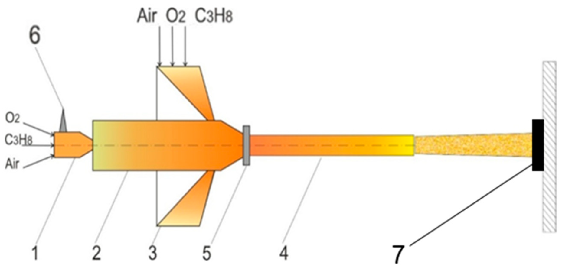
25], in which the powder material is heated and accelerated by the products of detonation combustion of a gas fuel mixture based on propane–butane, oxygen, and air. The design of the installation includes three chambers (
Figure 1): 1—a pre-chamber designed to initiate the detonation process; 2—the main cylindrical chamber in which the detonation combustion mode develops; 3—a ring chamber with a slit outlet into the cylindrical barrel (4). The ring chamber compresses the combustion products and forms an additional flow that supports the movement of detonation products from the main chamber (2) into the cylindrical barrel. The powder material is fed in front of the high-speed combustion products through the annular slot of the gas-dynamic feeder (5). Detonation combustion of the gas mixture is initiated by a spark plug (6) and sample (7).
The coating was formed directly on the surface of the samples without using any sublayer. The parameters of the combustible gas mixture, including its composition and component consumption are given in
Table 3.
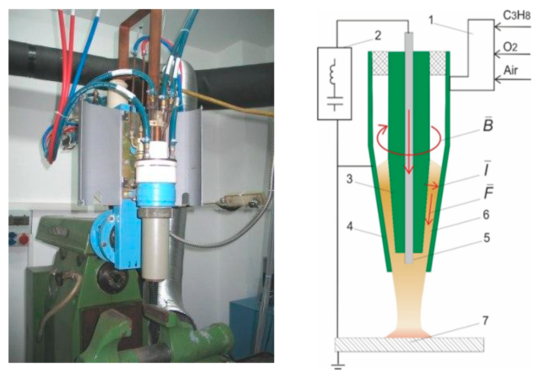
Some of the coated samples were treated with pulsed plasma using the Impulse-6 device (Ukraine, Kyiv), where heating and acceleration are provided by ionized gas behind the detonation wave front. This method allows plasma to be obtained with a frequency of 1–4 Hz, energy up to 7 kJ, and a heat flux of 10
4–10
6 W/cm
2, as well as introducing alloying elements into the flow. At the same time, the surface is rapidly heated and cooled at a rate of up to 10
7 K/s for 10
−3–10
−4 s, forming a fine-grained structure with a high dislocation density. The combined thermal, electromagnetic, and elastic-plastic effects enhance the physicochemical processes in the surface layer, which improves its strength and performance characteristics (
Figure 2,
Table 4).
X-ray phase analysis was carried out using an X’Pert PRO PANalytical diffractometer (PANalytical BV, Almelo, The Netherlands) equipped with a copper anode tube operating at 40 kV and 30 mA. Recording of Cu-Kα radiation (λ = 1.541 Å) was performed in the 2θ range from 20° to 90°, with a scanning step of 0.02° and a counting time of 0.5 s per step. Processing and interpretation of the obtained diffraction patterns were carried out using the HighScore Plus software package version 3.0.5. The cross-sectional microstructure of the sprayed coating was examined using a scanning microscope (SEM, Tescan Vega 4, Brno, Czech Republic). Corrosion tests were performed using a CS300 galvanostat–potentiostat (Corr testInstruments, Wuhan, China). Measurements were taken at a temperature of (25 ± 1) °C in a 3.5% aqueous NaCl solution. A three-electrode electrochemical cell was used for the study, where an Ag/AgCl electrode was used as the reference electrode and a platinum plate served as the auxiliary electrode. The corrosion potential (Ecorr) and corrosion current density (icorr) were determined from potentiodynamic polarization curves processed using the Tafel extrapolation method. The tests were performed on four samples, each of which was subjected to three repeated measurements to ensure statistical reliability. Potential scanning was performed in the range from −0.1 to +0.1 V, relative to the open circuit potential (OCP) at a rate of 0.5 mV/s. The data obtained was processed using CS Studio 6 software, which provides automatic approximation of Tafel sections and calculation of basic electrochemical parameters. For each coating, at least ten indentations were made in different areas of the cross-section, the average value was recorded, and microhardness was measured using a FISCHERSCOPE HM2000S (Helmut Fischer GmbH, Sindelfingen, Germany; ASTM E2546) at a load of 100 mN and an exposure time of 10 s. The surface roughness parameters of the coatings were evaluated using a model 130 profilometer (JSC ‘PROTON Plant’, Moscow, Russia). The main criterion for surface characteristics was the Ra parameter, which reflects the arithmetic mean of the profile deviations from the average line. This indicator provides the most complete description of the degree of surface irregularities and serves as a quantitative characteristic of its quality after coating application. Microstructural studies were performed using transmission electron microscopy. Samples were prepared using a scanning electron microscope with a gallium ion beam system based on Ga-FIB FEI Helios NanoLab™ 600i (Thermo Fisher Scientific, Waltham, MA, USA). A Hitachi H-800 transmission electron microscope with a maximum accelerating voltage of 200 kV was used for observations.
3. Results and Discussion
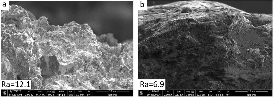
Figure 3 shows the results of scanning electron microscopy (SEM) of the surface of the Fe–TiB
2–CrB
2 detonation coating before (
Figure 3a) and after (
Figure 3b) pulsed plasma treatment (PPT). The surface of the initial coating (
Figure 3a) is characterized by a developed relief with pronounced protrusions, depressions, and sharp ridges typical of uncompacted gas-thermal layers. The high amplitude of micro-irregularities is due to the spray lamellar structure and the presence of open pores. The arithmetic mean deviation of the profile is Ra = 12.1 μm, which indicates significant roughness and high surface energy. After pulsed plasma treatment (
Figure 3b), a pronounced smoothing of the micro-relief is observed: the tops of the lamellae are partially melted and joined into more uniform ridges, and the deep depressions are levelled. The average roughness value decreases to Ra = 6.9 μm, i.e., almost twice (a decrease of approximately 43%). This morphological change is explained by the short-term exposure to a high-density thermal pulse, causing local melting and subsequent recompaction of the upper coating layer. The thickness of the compacted layer is about 15–30 microns. As a result, the amplitude of micro-irregularities decreases, the uniformity of the surface layer increases, and the proportion of open defects decreases. A decrease in the Ra parameter indicates an increase in the degree of compaction and a potential improvement in the functional characteristics of the coating—in particular, an increase in wear and corrosion resistance due to a reduction in the active surface area and concentration of microdefects.
Figure 4 shows the diffractograms of coatings based on the eutectic alloy Fe–TiB
2–CrB
2, obtained by detonation spraying. The diffractogram of the initial coating (
Figure 4a) shows intense peaks corresponding to the α-Fe and γ-Fe phases, as well as refractory boride compounds CrB
2 and TiB
2. The presence of these phases confirms the preservation of the eutectic structure of the detonation coating, where the iron matrix acts as a binding phase and the borides form reinforcing inclusions. After pulse plasma exposure (
Figure 4b), a redistribution of the phase composition is observed: the intensity of the α-Fe peaks increases, while the γ-Fe reflections decrease. After pulse plasma treatment, the appearance of additional CrB
2 and TiB
2 reflections is recorded. This indicates the occurrence of diffusion interaction processes at the interface and partial redistribution of alloying elements. The amplification of α-Fe peaks indicates the formation of a more homogeneous metal matrix with a decrease in residual stresses. The appearance of additional boride phases (CrB
2, TiB
2) indicates their stabilization and thermal stability under pulsed plasma heating conditions. Thus, pulsed plasma treatment contributes to the formation of a more stable heterophase structure with a reduced proportion of metastable austenite and increased thermal stability.
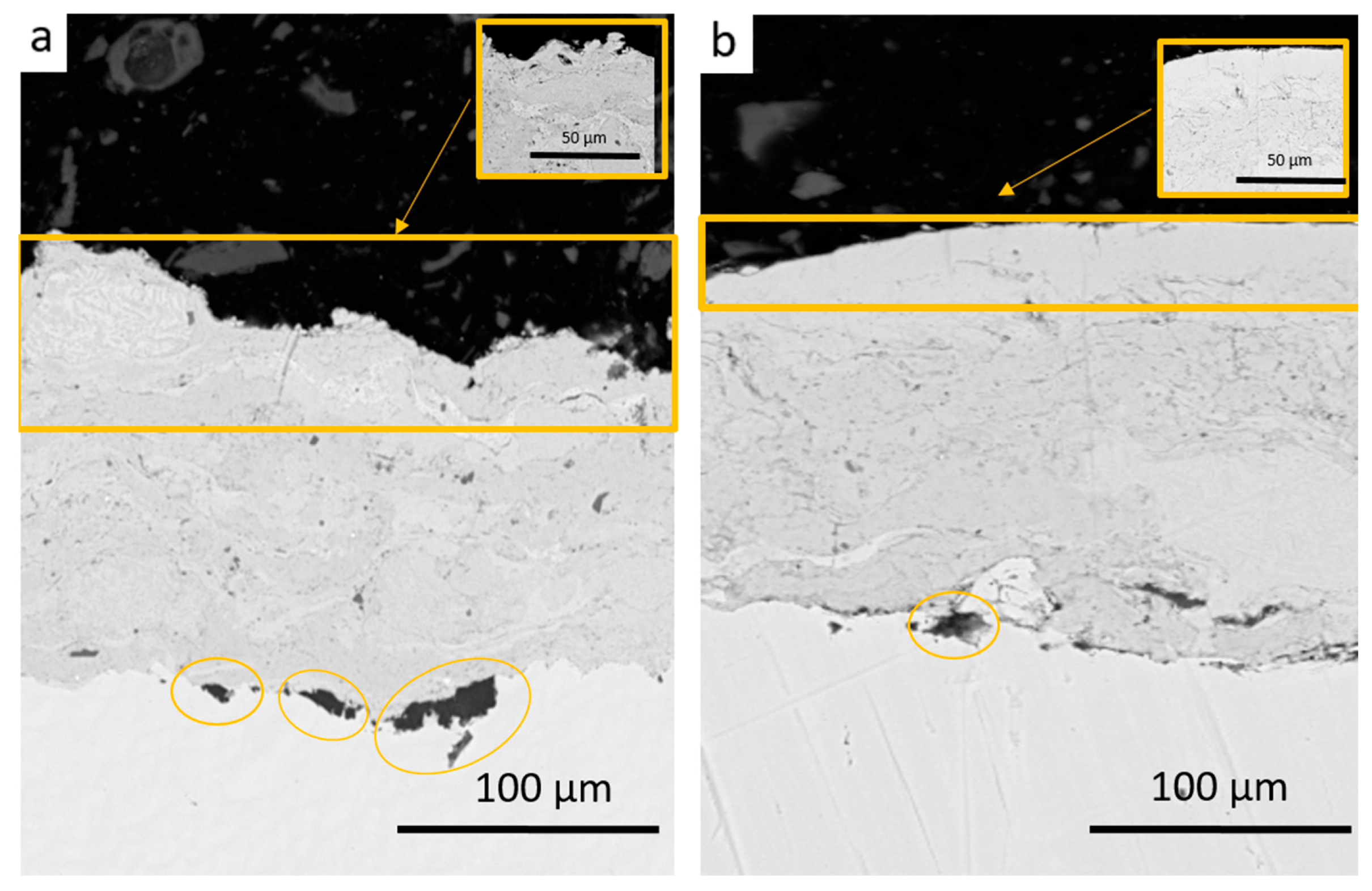
Figure 5 shows the results of scanning electron microscopy (SEM, BSE contrast) of cross sections of Fe–TiB
2–CrB
2 detonation coatings. Before pulse plasma treatment (
Figure 5a), the coating in its initial state is characterized by a lamellar structure typical of detonation technologies. There is a clear boundary between the coating and the substrate, but the structure of the coating is heterogeneous: there are interlamellar voids, microcracks, and pores associated with incomplete sintering of the particles. In the near-surface zone, a loose texture with separate unalloyed fragments and spray particles is observed, indicating incomplete formation of the surface layer. At the boundary between the coating and the substrate, there are isolated black areas representing pores, non-metallic inclusions, and localized areas of incomplete adhesion. Their formation is associated with the high cooling rate during detonation spraying and the uneven temperature distribution at the moment of particle impact on the surface. After pulsed plasma treatment (
Figure 5b), the structure of the coating undergoes significant changes. Visually, the surface zone becomes denser, and the micro-relief is smoothed out, with a reduction in the number of pores and interlamellar defects. A thin, overcompacted layer with a thickness of about 15–30 μm forms in the upper part of the coating, characterized by increased contrast and uniform texture. The boundary with the substrate remains clear, with no signs of thermal destruction or delamination. Local areas highlighted in enlarged inserts show increased particle density and a reduction in average grain size.
Morphological changes after PPT are explained by the action of a high-density thermal pulse, causing short-term melting of surface fragments and their rapid recrystallization. This leads to sealing of interlamellar boundaries, reduction of porosity, and formation of a more cohesive, dense structure. The number and size of dark defective areas on the interface are significantly reduced. This is due to the fact that PPT causes short-term surface melting and recrystallization, accompanied by coating compaction and diffusion redistribution of elements at the interface. As a result, a denser and more coherent transition layer is formed, which increases the adhesive strength of the coating.
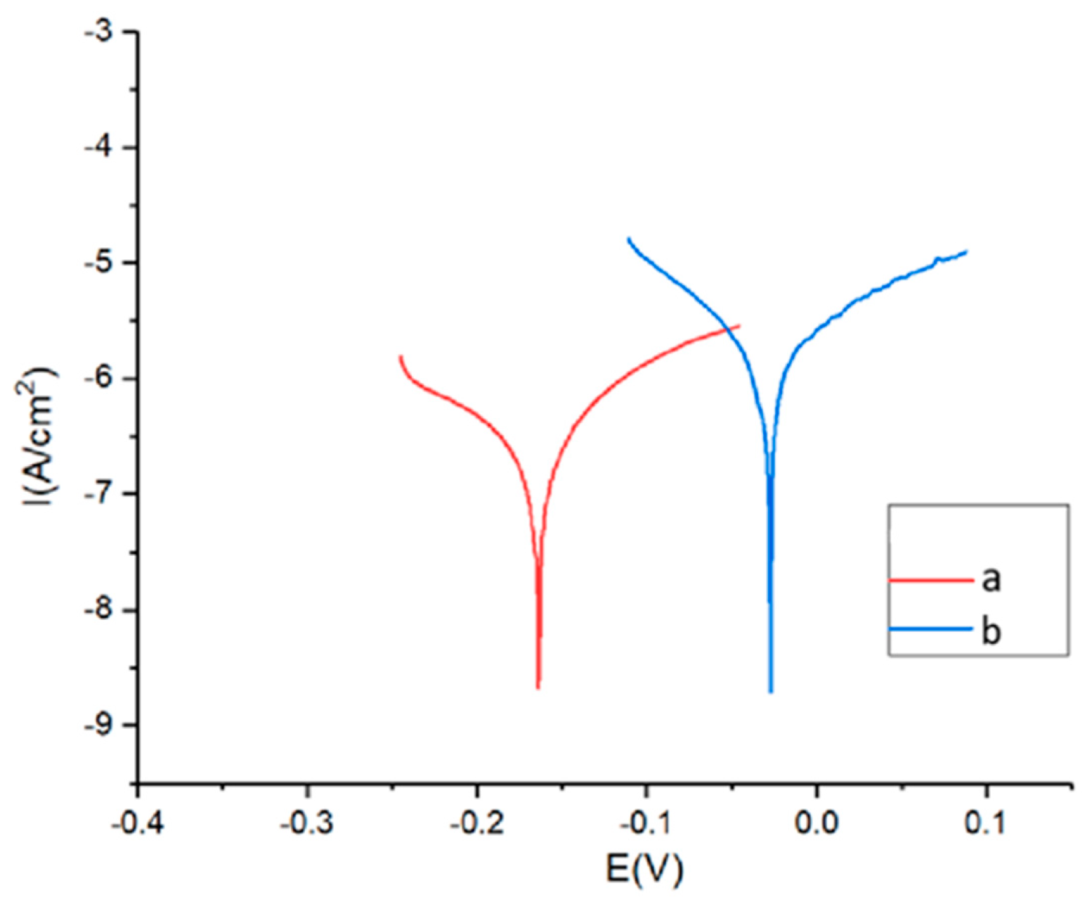
Figure 6 shows the potentiodynamic polarization curves of the Fe–TiB
2–CrB
2 coating measured in a standard three-electrode cell. The analysis results show that after pulse plasma treatment (curve b), the corrosion potential shifts to the positive side, and the corrosion current density decreases compared to the initial coating (a). This indicates an increase in the corrosion resistance of the treated coating. The decrease in current density and stabilization of the potential indicate the formation of a denser and more uniform protective film, which may be due to the compaction of the microstructure and a decrease in porosity after exposure to the pulsed plasma discharge. Thus, the treatment improves the barrier properties of the coating and slows down electrochemical corrosion processes. The results of electrochemical tests showed a positive shift in the corrosion potential of ~0.15 V and a decrease in the corrosion current density by approximately 1.5–2 times.
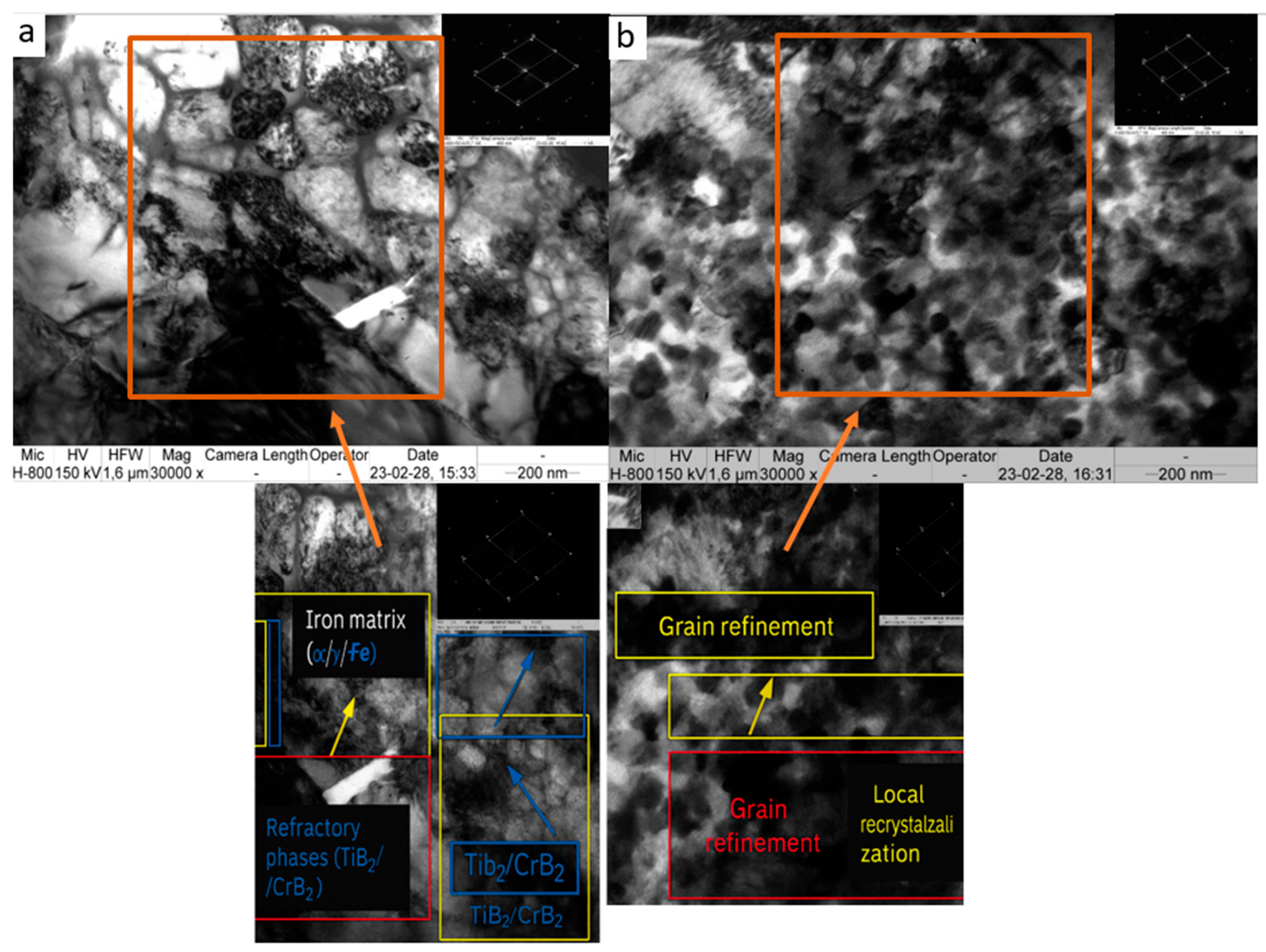
Figure 7 shows the results of transmission electron microscopy (TEM) and electron diffraction analysis of coatings based on the eutectic alloy Fe–TiB
2–CrB
2.
In its initial state (
Figure 7a), the structure is characterized by a pronounced lamellar morphology typical of detonation coatings. Large eutectic colonies are observed in the iron matrix (marked in yellow), as well as boride inclusions of TiB
2 and CrB
2 (blue areas), evenly distributed in the metal phase. The structure contains interlamellar defects and micropores (yellow areas), indicating incomplete sintering of particles during deposition. The electron micrograph shows characteristic reflections for hexagonal boride lattices (planes (101), (002), (103)) and the cubic lattice of γ-Fe (reflections {111}, {200}, {220}), confirming the polycrystalline nature of the coating.
After the PPT (
Figure 7b), the structure undergoes significant changes: a decrease in grain size and an increase in material density are observed due to the thermal energy effect of plasma. Areas of recrystallization and grain refinement (red zones) are formed, as well as local areas of overcompaction with uniform phase distribution. A decrease in the intensity of γ-Fe reflections and an increase in diffractions from boride phases on the electron diffractogram indicate an increase in the proportion of stable refractory components and a decrease in the number of metastable austenitic areas.
Thus, pulsed plasma treatment contributes to microstructure compaction, porosity reduction, recrystallization, and grain refinement, which improves the adhesive strength, microhardness, and corrosion resistance of the Fe–TiB2–CrB2 coating.
Figure 8 shows the results of the hardness measurements. In the initial state, the microhardness value in the near-surface zone is about 14 GPa, gradually decreasing to 13–12 GPa as the measurement depth increases. This behavior is associated with the presence of a lamellar structure, micropores, and relatively weak sintering between coating particles, which is characteristic of detonation spraying.
After pulse plasma treatment, a significant increase in hardness is observed in the surface area—up to 17–18 GPa, which is ~15%–20% higher than in the initial state. At depths greater than ~100–150 μm, the values of both curves become practically identical (13–12 GPa), which indicates the local nature of hardening in the zone of thermal influence of the plasma pulse.
The increase in microhardness in the surface layers after PPT is due to the compaction of the structure, a reduction in grain size, and the formation of finely dispersed carbide-boride phases, which is confirmed by TEM and XRD results. At the same time, the increase in hardness is accompanied by an improvement in the cohesive properties of the coating due to the sealing of interlamellar boundaries and partial remelting of surface microdefects.
The characteristic sharp drop in hardness values at the end of the measurement range (deeper than ~180 μm) is explained by the transition of the indenter zone into the substrate area, where the material has lower stiffness.
4. Conclusions
Coatings based on the eutectic alloy Fe–TiB2–CrB2, obtained by detonation spraying, have a pronounced lamellar structure with alternating iron matrix and refractory boride phases TiB2 and CrB2. Pulsed plasma treatment had a significant effect on the microstructural state, phase composition, and functional characteristics of the coatings. Transmission and scanning electron microscopy revealed that PPT resulted in compaction of the surface layer, reduction in grain size, and reduction in the number of pores and interlamellar defects. The thickness of the modified zone is about 15–30 μm. Local areas of the structure become finely dispersed, which indicates the development of recrystallization and partial remelting of surface micro-irregularities. Electron diffraction and pulse plasma treatment leads to the formation of a finer and thermodynamically stable structure, an increase in the degree of crystallinity of boride phases and improved structural uniformity of the coating. This contributes to an increase in its hardness, wear resistance, and adhesive strength compared to the original detonation coating. This indicates phase stabilization and thermodynamic equilibrium of the system after PPT. According to microhardness measurements (Fischerscope), the hardness of the near-surface layers increased from ~14 GPa to 17–18 GPa, which is associated with grain coarsening, compaction, and the formation of strengthening boride–carbide inclusions.
The results of electrochemical tests showed a positive shift in corrosion potential of ~0.15 V and a decrease in corrosion current density by approximately 1.5–2 times. This indicates an improvement in the passivating properties of the surface and a decrease in its electrochemical activity due to the sealing of interlamellar defects and the formation of a thin protective oxide-boride film.
Thus, pulsed plasma treatment provides structural and phase improvement of Fe–TiB2–CrB2 detonation coatings, leading to a decrease in porosity and an increase in density; grain refinement and compaction; stabilization of the α-phase of iron; and an increase in microhardness and corrosion resistance.
Taken together, the studies confirm that PPT is an effective method for improving the performance characteristics of eutectic coatings based on Fe–TiB2–CrB2, ensuring their structural integrity, corrosion and wear resistance, as well as their suitability for use in high-temperature and aggressive environments.
