Article

Laser Fabricated MgO-TiO2 Based Photocatalytic Antifogging and Self-Cleaning Surface in Air

Department of Materials Science, School of Civil Engineering, Qingdao University of Technology, Qingdao 266520, China
*
Author to whom correspondence should be addressed.
Coatings 2025, 15(10), 1214; https://doi.org/10.3390/coatings15101214
Submission received: 13 August 2025 / Revised: 30 September 2025 / Accepted: 11 October 2025 / Published: 15 October 2025
(This article belongs to the Special Issue Applications of Self-Cleaning Photocatalytic Coatings)

Abstract

A cost-effective laser marker was employed to fabricate a superhydrophilic, photocatalytic Mg-Ti-based surface on glass under ambient conditions. The photocatalytic layer was first deposited via laser processing, followed by partial laser etching to generate micro/nanostructures on the surface. This method preserves partial photocatalytic functionality while enhancing surface roughness and introducing unique nanostructures, enabling the sample to simultaneously exhibit antifogging, self-cleaning capabilities, and high light transmittance. The optimal sample was achieved by tuning laser processing parameters, including repetition rate and scanning hatch distance. It maintained a water contact angle (WCA) of 0° after 15 days of outdoor exposure, which only increased to 21.2° after 30 days. In comparison, the WCA of reference glass increased from an initial 23.3° to 63.9° over the same period. Furthermore, the amount of dust accumulated on the optimal sample was significantly lower—by up to 43%—than that on the reference glass over one month under both indoor and outdoor conditions. After a single spray cleaning, the dust removal efficiency of the indoor-stored optimal sample reached 70%, which was 56% higher than that of the reference. For samples stored outdoors, a single spray removed 67% of the dust from the optimal surface, compared to only 26% for the reference, highlighting its excellent self-cleaning performance. Additionally, the optimal also showcased remarkable antifogging property, which had been maintained over the one-month exposure period without visible degradation. Moreover, the optimal sample exhibited a 2% enhancement in broadband light transmittance across the 400–1000 nm wavelength range, demonstrating strong potential for photovoltaic applications. The simultaneous achievement of antireflection, antifogging, and self-cleaning performance under both indoor and outdoor conditions over a one-month period has rarely been reported in the literature.

1. Introduction

Glasses are made of quartz sand, soda ash, and limestone and are widely used in photovoltaics, auto-glass, and medical endoscopes [1]. To address the challenges faced by photovoltaic (PV) glass, advanced surface-sensitive technologies are crucial—enabling quantitative characterization of micro/nanoscale surface features, dynamic surface reactions, and carrier dynamics [2,3]. Some of which may also apply to PV glass covers in the future. Dust adhesion and moisture atomization are yet two major and urgent challenges to be solved. Due to the outdoor environment, dust can be deposited and adhere to the surface of solar panels, blocking the light from entering the active layer, which leads to a decrease in photovoltaic conversion efficiency [4]. Dust on glass in a humid environment will eventually cause a cementation reaction, where the dust particles chemically bond with the glass surface [5,6,7], and it will stick firmly to the glass and must be removed by wiping hard with the necessary chemicals. This method may scratch the glass [8], reduce the light transmission, and further decrease the efficiency of the PV panels. Moreover, the cleaning agent may pollute the environment. The labor cost of cleaning is 100,000 Chinese yuan per MW, and a large amount of fresh water is consumed, which is estimated to be hundreds of millions of tons per year, and is unsustainable. Therefore, there is an urgent need for self-cleaning technologies [9].
According to Young’s equation [10] and Wenzel model [11], the surface energy and surface roughness of a solid determine its water contact angle. Surface modification is a promising self-cleaning method for antifogging, self-cleaning of superhydrophilic or superhydrophobic surfaces [12,13]. Specifically, superhydrophobic surfaces, which require complex fabrication processes and are limited to laboratory practice, allow water droplets to roll due to gravity and energy changes caused by droplet coalescence, carrying enclosed surface contaminants, achieving self-cleaning [14]. In contrast, the affinity of superhydrophilic surfaces to water exceeds their adhesion to pollutants. Water molecules penetrate between the surface and the contaminant, spreading into a thin uniform film of water. The isolated pollutants are stripped away by wind or rainfall, a process known as superhydrophilic self-cleaning [15]. On the contrary, a large amount of water is required for a superhydrophobic surface to capture and carry away the same amount of contaminants as in the above case [16]. It has been reported that surfaces with smaller contact angles accumulate less dust compared to surfaces with larger contact angles [17]. And superhydrophilic coatings are 2.5 times more resistant to dirt than superhydrophobic coatings [18]. Conventional superhydrophobic surfaces are highly susceptible to organic pollutants such as grease and oil due to their surface properties [19]. Once these pollutants are attached, the superhydrophobicity gradually decreases over time, eventually leading to a complete loss of its self-cleaning function [20,21]. On the contrary, superhydrophilic surfaces are effective in removing organic fouling [22]. However, organic contaminants decrease superhydrophilicity over time and need to be removed [23]. Photocatalysts effectively remove organic pollutants through photocatalysis, and titanium oxide nanoparticles are one of the most commonly used photocatalysts [24], but they need to be activated by strong UV irradiation and usually have poor durability [25]. Meanwhile, the reflection is high thanks to the high refractive index of titanium oxide. Therefore, this paper focuses on the balance between superhydrophilic antifogging, self-cleaning, and transmission properties.
Many efforts have been made for this purpose. He et al. [26] deposited a mesoporous SiO2-TiO2 composite coating on a glass substrate by the dip coating method. A mechanically robust hybrid film with high transmittance and long-lasting superhydrophilicity was produced, which lost its superhydrophilicity after 105 days of storage in the dark and still required UV irradiation to recover its properties. Pilspanen et al. [27] sprayed TiO2-Ag sols onto the glass by the sol-gel method, which made the glass surface transparent and also showed antifogging and self-cleaning effects at the same time. However, the coated surface absorbs in the near-ultraviolet region, and the overall transmittance of the coated surface is slightly lower than that of the uncoated glass in the entire wavelength region studied (380–1000 nm). Zhang et al. [28] prepared a TiO2-PHEA nanocomposite coating. The coating maintained superhydrophilicity for up to 330 days in a laboratory environment. However, the transmittance of the samples was slightly lower than the reference. Moreover, the minimum contact angle of the freshly prepared samples was only about 2.5°, which indicates that improvement is needed for practical outdoor applications. Cui et al. [29] prepared core-shell Ti/W-based photocatalytic films with superhydrophilic self-cleaning properties by laser, but this also led to a loss of light transmittance performance. To date, the preparation of antifog and self-cleaning surfaces with long-term outdoor durability and high light transmittance remains a challenge [30]. In addition, there are few studies related to actual indoor/outdoor dust accumulation measurements, and the large number of field pictures in this study provides visual support in this area.
The laser marking machine is a simple, efficient, and low-cost laser marking machine that has been demonstrated to generate nanostructures on glass. Our research group has used laser etching of coated glass to fabricate microstructured surfaces, resulting in greatly improved light transmission [31,32]. During the laser etching process, most of the laser energy is used to etch coatings with little oxidized residue, and very little energy is used to etch the glass, resulting in the formation of shallow micrometer structures. Whereas, large microstructures will cause transmission loss [13]. According to Mie scattering theory [33], this shallow structure does not cause significant scattering losses. Note that the glass is coated by vacuum sputter deposition. Combining the previous research on laser-deposited photocatalytic coatings [34] and laser-etched coated glass [31,32], the goal of this study is to combine the micro- and nanostructured surfaces with the photocatalytic surface layer to form a superhydrophilic surface with antireflective and photocatalytic functions for long-term outdoor applications.
Mg and its alloys have become highly promising structural materials by virtue of their lightweight characteristics, excellent damping properties, and good machinability [35,36]. Consequently, Mg has been widely used in biomedicine, batteries, and hydrogen storage and has also gained extensive academic attention [37,38]. There have also been studies on the superhydrophobicity of Mg using one-step hydrothermal method, chemical vapor deposition, electrodeposition, and other technological means to construct superhydrophobic coatings on their surfaces for corrosion protection [39,40,41]. In the literature, most Mg-based coatings are associated with hydrophobicity for anti-corrosion [38]. Hydrophilic Mg-based coatings are mainly applied in the biomedical field, and their preparation methods are relatively complex [42]. In this paper, the Mg-based and Mg-Ti-based systems have achieved the multifunctional synergy of hydrophilicity, antifogging, self-cleaning, and high light transmittance on glass with relatively simple laser-fabrication in air. It is noteworthy that Mg, as one of the alkaline-earth metals, has a very low standard electrode potential (−2.363 V) and a very high chemical activity, and its surface usually exhibits strong water-absorbing properties [43], which provides an important theoretical basis for its use in superhydrophilicity. Therefore, Mg was adopted for coating glass. In order to further enhance the photocatalytic activity of the surface, titanium was also introduced into the laser deposition and etching process. Some self-cleaning coatings are prepared by directly spraying nano-TiO2 onto substrates, and their hydrophilicity depends solely on the inherent properties of TiO2 itself, rather than relying on the regulation of hierarchical micro/nanostructures [44]. It requires intense UV activation, and its high refractive index leads to transmission loss [29]. Although SiO2-TiO2 coatings optimize their surface morphology by constructing lotus leaf-like hierarchical micro/nanostructures via the sol-gel method, they still require complex and energy-consuming preparation processes without field test results [45]. In contrast, the novel laser marker processing in air broke through the equipment and cost limitations of traditional preparation methods. Meanwhile, MgO has a low refractive index, reducing the index of the composite and therefore reduces reflection [46]. This is also the first report on Mg-Ti for the simultaneous achievement of antifogging, self-cleaning, and antireflection under natural sunlight for over 30 days of practical indoor and outdoor exposure. Previously, the glass coating was conducted in a vacuum sputter [47]. This makes laser-fabrication in air even attractive for actual applications.
Choosing an atmospheric environment over a vacuum environment essentially boils down to the optimal balance of performance requirements, cost, and efficiency. When the application scenario of the film does not require the advantages of “ultra-high purity and precisely complex structure” offered by a vacuum environment, the atmospheric environment avoids the complexity and high cost of vacuum technology by simplifying equipment, reducing costs, and improving efficiency. It is particularly suitable for the low-cost, large-scale fabrication of films for potential scale applications.

2. Experimental Methods

2.1. Materials and Methods

The soda-lime glass substrate (50 mm × 50 mm × 1.5 mm, from Guluo Glass Co. Ltd, Luoyang, China) was first cleaned in an ultrasonic cleaner using deionized water, isopropyl alcohol, and acetone in a sequence of 5 min each. This step was performed to remove dust and other debris adhering to the glass surface. The laser (YLP-M60, Liaocheng City Baiju Laser Equipment Co. Liaocheng, China, total power 60 watts) was operated at a wavelength of 1064 nm, a pulse duration of 100 ns, a focused beam diameter of 50 μm, a cross-sectional area at the focal point of 1600 mm2, a power setting of 50%, a repetition frequency range of 20–200 kHz, a scanning speed of 2 m/s, and line spacings of 0.01, 0.02, 0.03, and 0.04 mm, for laser etching. The Mg target (50 mm × 50 mm × 3 mm, from Guanyue Metal Materials, Shenzhen, China) was placed under the glass substrate with a 2 mm distance. The 2 mm distance is denoted as D. Please note that the variables were laser line spacing and repetition frequency for the laser deposition and etching process, while all other laser parameters remained unchanged.
The laser deposition and etching process was illustrated in Figure 1. The preparation of a Single Mg film begins with the deposition operation. The laser was focused on the surface of the Mg sheet with the laser line spacing set to 0.5 mm and frequency at 100 kHz. After the deposition was completed, the Mg sheet was removed, and the height of the glass substrate was adjusted to the laser focal point for etching the deposited Mg film. The etching parameters were listed in Table 1. The preparation of Ti film is the same as the aforementioned treatment.
The Mg-Ti deposition and co-etching process was performed by sequentially depositing Mg and Ti films, followed by co-etching with parameters in Table 1. The sample name starts with Co-MgTi.
The sequential Mg-Ti deposition and etching method started with Mg deposition and etching, and ended with Ti deposition and etching. The sample name starts with Se-MgTi.

2.2. Characterization

The surface morphology and composition were analyzed by scanning electron microscopy (SEM, Sigma 300 CARL ZEISS, Oberkochen, Germany) and energy dispersive spectrometry (EDS). The structure of the samples was analyzed by a Raman Spectrometer (DXR12, Thermo Fisher Scientific, Waltham, MA, USA). The chemical composition of the etched sample surface was analyzed by X-ray photoelectron spectroscopy (AXIS Ultra DLD, Kratos, Tokyo, Japan), and the contours of the surface structure were characterized by laser confocal scanning microscopy (VK-X1050 Keyence, Osaka, Japan). Optical measurements were performed using a spectrophotometer (Lambda 1050 from PerkinElmer, Shelton, CT, USA). Transmittance Accuracy was within 0.05% T (0%–100% T, referenced to standard whiteboard). The static water contact angle (WCA) was measured using a goniometer (DLDA23-01, Zhuhai Dalve, Zhuhai, China). The samples were subjected to controlled experiments in both indoor and outdoor environments. The surface of the treated sample was tested by the static water contact angle measurement using a 1 μL water droplet.

2.2.1. Self-Cleaning Test

The experiments were conducted in a controlled design: samples were prepared and placed indoors and outdoors, with a blank reference glass for each group, either indoor or outdoor test. Notice that the indoor environment was not in a cleanroom condition, which was rather tough for superhydrophilicity since a superhydrophobic experiment was also conducted in the lab with residual volatile fluorsilane in the ambient [48]. On days 3, 7, 15, 21, and 30 of the experiment, images of at least three different areas of each sample were captured by an optical microscope (Dino-Lite AM3113, AnMo Electronics Co., Taiwan, China) using DinoCapture 2.0 software at a magnification of 225×. The captured images were then imported into the Nano Measurer 1.2 software, and the amount of dust particles in the imaged area was counted to assess the degree of surface contamination. In order to simulate natural rainfall conditions, a 500 mL water sprayer (with a single spray volume ~1.5 mL) was used to spray water on the sample glass and the reference glass. A single spray in the middle of a sample was for the test. (The treatment process involves aiming the nozzle at the vertically placed sample for a single spray. The contact angle is measured after the water droplets on the glass surface have completely dried. In the experiment, the sample is placed vertically to enhance the dust removal effect through the synergistic action of gravity and water flow.) The amount of dust particles before and after water spraying was recorded, and the self-cleaning performance of the materials was quantitatively evaluated by comparing the number of dust particles before and after the spraying on the coated sample and reference.

2.2.2. Antifog Durability Test

To comprehensively evaluate the antifogging performance of the samples, multiple groups of samples with the same specifications were prepared and placed in parallel in indoor and natural outdoor environments, with a reference glass set as a control. The antifog test was conducted every 7 days within one month. During the test, the samples were placed vertically, facing directly to the outlet of a humidifier at a distance of 50 mm for 5 s. Under unified lighting and background conditions, the antifogging effects of all samples and the reference glass were observed and compared simultaneously with photos taken for the record. The test was carried out in real time, and the background displayed the official website of the Greenwich Observatory showing Beijing time.

2.2.3. Aging Test

A new set of Single Mg film, Mg-Ti sample was placed under an ultraviolet (UV) lamp (365 nm, 50 W, OHSP-350UV from Hangzhou Hopoo Light&Color Technology Co. Ltd., Hangzhou, China) for uniform irradiation over 50 h, with the distance between the lamp and the samples fixed at 5 cm, which is equivalent to 1600 h of outdoor irradiation [49]. The aging degree of the samples was evaluated by measuring their transmittance, contact angle, and water spreading-out time. To ensure the accuracy of the experiment, three tests were conducted on each sample for the average.

2.2.4. Photocatalytic Decomposition of MO

Each unetched sample was immersed individually in a Petri dish containing 20 mL of 4 mg/L MO (Kunfuxing Laboratory Supplies Co. Ltd., Qingdao, China) solution. The distance between the UV lamp and the solution was fixed at 20 cm. The degradation of MO by the films was monitored by measuring the UV-visible absorption spectrum of the MO solution, particularly at the maximum absorption wavelength of 460 nm.

2.2.5. Abrasion Resistance Test

A new set of Single Mg film, Mg-Ti Sample, was prepared, with the film side facing a piece of sandpaper (SP60, length 25 cm, from SEP Ltd., Wenzhou, China). A 500 g weight was placed on top of the samples, and then the samples were pushed to move on the sandpaper, with “one back-and-forth movement” defined as one friction cycle. The wear resistance of the samples was indirectly evaluated by monitoring the changes in the contact angle.

3. Results and Analysis

3.1. Surface Morphology

Figure 2a–d shows the SEM images of Single Mg films with different frequencies. As the frequency increases, the size and irregularity of the nanostructures on the surface gradually decrease. Since the pulse distance is equal to v/f [50], increasing f means decreasing pulse distance and increasing laser etching. 20 kHz corresponded to insufficient etching, leading to irregular, large structures. On the other hand, 200 kHz might be associated with overetching, with much less nanostructures left. Dense and uniform structures are instrumental to water diffusion and hydrophilicity [31]. The optimal 100 kHz resulted in nanoscale particles with uniform size and dense distribution. The formation of larger nanoscale particles in Figure 2c may be due to agglomeration [29]. Figure 3a–d presents the SEM images of Single Mg films with different line spacings. In comparison with other line spacings, the line spacing of 0.03 mm led to nanoscale particles with more uniform size and distribution. 0.01 mm resulted in overetching and irregular particles, while 0.04 mm had only slight etching with much less structures. Neither overetching nor underetching was beneficial for hydrophilicity. Figure 4 is the SEM image of the Mg-Ti sample. Nanoparticles can be observed in Figure 4a,b, which are generated under the drive of thermal equilibrium between hot electrons and cold lattices. Surface electrons absorb laser energy and rapidly transfer it to the lattice. The high-power density induces explosive vaporization, generating a plasma plume composed of neutral atoms, ions, clusters, and nanoparticles [51]. Due to the huge pressure and temperature difference between the plasma and the surrounding, it collapsed with the nanoparticles from both the plume and the melting pool underneath splashing around, which cooled down at a high speed, quickly returned to the surface through solidification or redeposition, and finally formed the surface structure of nanoparticles [52,53]. Se-MgTi had a more uniform and dense distribution of nanoparticles than Co-MgTi.
Figure 5 is the EDS mapping image of Se-MgTi with a line spacing of 0.03 mm. It can be seen from these figures that Mg, Ti, and O were widely and uniformly distributed on the surface.

3.2. Surface Structure Analysis

The surface morphologies of the treated samples were characterized using a confocal microscope, and the results are shown in Figure 6. Relatively uniform and regular microstructures were formed on the Se-MgTi sample surface, which were characterized by shallow depressions surrounded by narrow protrusions forming regular channels. This was consistent with the observation results of SEM. Such regular channels facilitated water spreading. In addition, the roughness of the Se-MgTi sample was generally higher than Co-MgTi and single Mg samples. The results in Figure 6b show that the roughness of the Co-MgTi sample with a line spacing of 0.02 mm was significantly higher than that of other line spacing groups, meanwhile forming a uniform and dense microstructure, which is conducive to the effective diffusion of water droplets. The results in Figure 6c indicate that the surface roughness of Se-MgTi is further improved, among which the Se-MgTi with a line spacing of 0.02 mm exhibited the highest roughness (Sa = 0.291 μm), forming the most uniform channels.
According to Wenzel model [11] and other previous studies [31], Se-MgTi with 0.02 mm line spacing may perform best in superhydrophilicity.

3.3. Chemical Composition Analysis

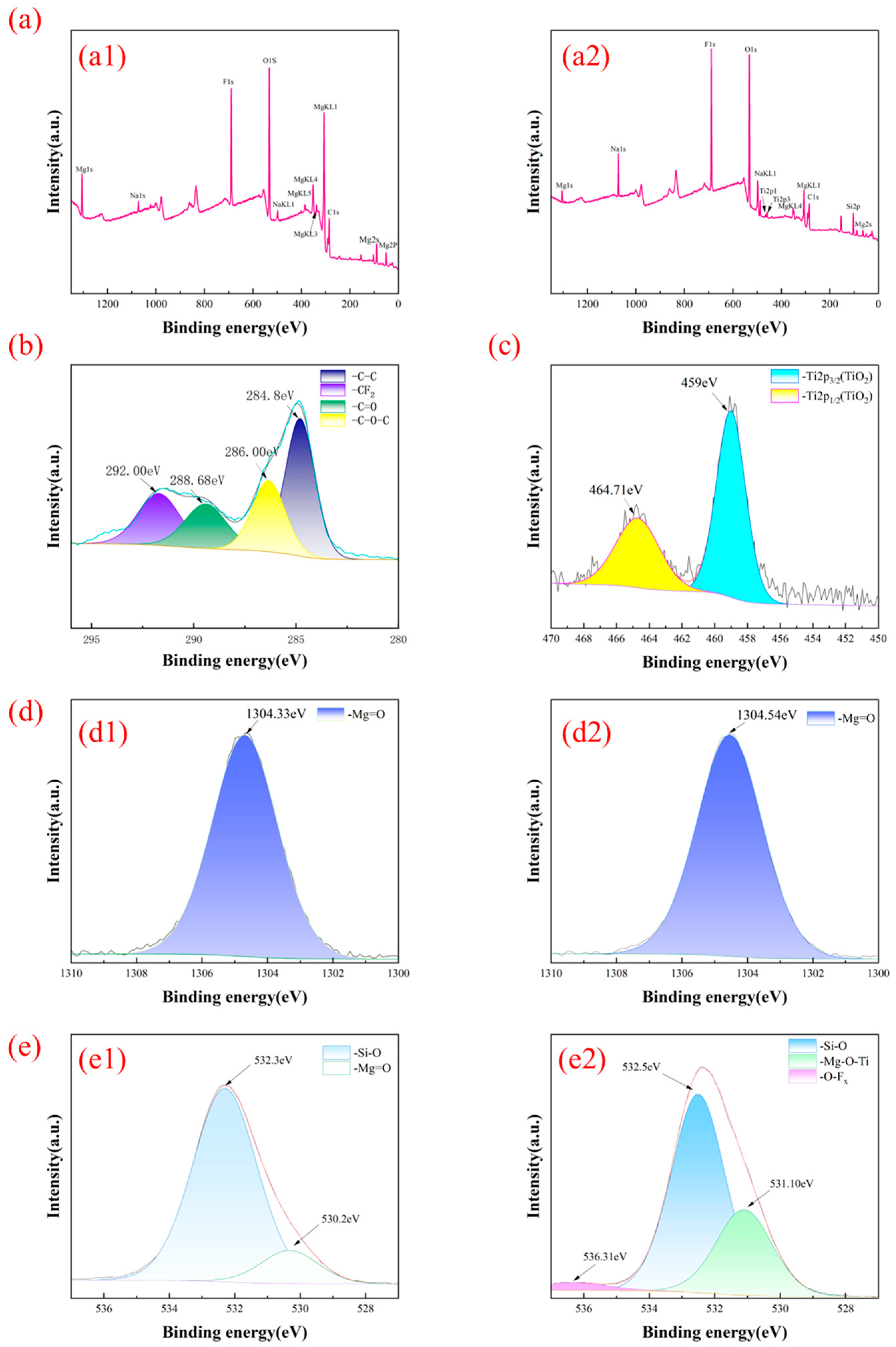
Figure 7 shows XPS spectra of samples, which were calibrated according to the C1s energy level at 284.8 eV. Polar bonds formed by O, Mg, Si, and Ti increase the surface polarity and dominate the composition as seen in Figure 7a. For a Single Mg film sample, carbon content on the surface accounted for only 26.67%, where the nonpolar C-C bonds accounted for 38.77% and C-F bonds accounted for 22.57% of the total C content. The higher contents of O (30.91%), Mg (16.29%), and Si (3.27%) significantly enhance the surface polarity, and for the Mg-Ti sample, higher contents of O (31.58%), Mg (9.67%), Si (8.22%) and Ti (1.83%) compared to C (23.25%) also increased the surface polarity due to the majority of polar bonding, Figure 7b shows the C1s spectrum. The C1s spectra have four main peaks located at 284.8 eV, 286 eV, 288.68 eV, and 292 eV, which correspond to the C-C bond, C-O-C bond, C=O bond, and C-F bond, respectively. The presence of the C and F elements was mainly attributed to the adsorption of organic pollutants from the ambient during the fabrication, storage, and delivery of the samples. Figure 7c shows the Ti2p spectrum, which was deconvoluted into Ti2p3/2 peaks at 459 eV and Ti2p1/2 peaks at 464.71 eV. Figure 7d shows the Mg1s spectrum. The Mg1s spectrum has a main peak at approximately 1304.5 eV, which corresponds to the polar covalent Mg=O bond, effectively enhancing the hydrophilic properties of the glass. Figure 7(e1) shows the O1s spectrum of the Single Mg film. The characteristic peak at 530.2 eV corresponds mainly to the polar covalent Mg=O bond, and the characteristic peak at 532.3 eV corresponds to the Si-O bond. Figure 7(e2) presents the O1s spectrum of Se-MgTi, where the characteristic peak at 531.10 eV is attributed to the metal oxide peak. Notably, compared with the Single Mg film, this peak has shifted by approximately 0.9 eV. The characteristic peak at 532.5 eV corresponds to the Si-O bond, and the characteristic peak at 536.31 eV corresponds to the O-Fx bond, which may be due to contamination. In addition, Mg involvement increased the integral intensity of the characteristic peak at 531.10 eV, which may be due to the generation of oxygen vacancies [54]. Additionally, the binding energy of Ti 2p3/2 shifted higher by about 0.3 eV, and the binding energy of Mg 1s also shifted higher. These shifts may be due to the formation of Mg-O-Ti bonds. Mg involvement may increase active O species, such as O vacancy, because limited O in the local environment preferentially reacts with Mg with insufficient oxidation of Ti, which enhances photocatalysis. This result is consistent with findings in the literature [55]. In addition, Ti and O were combined mainly in the form of TiO2, which tended to form a polar bond. The hydrophilicity of glass surfaces was determined by the relative contents of polar bonds over nonpolar bonds [56]. Dominant polar bonds enhanced hydrophilicity.
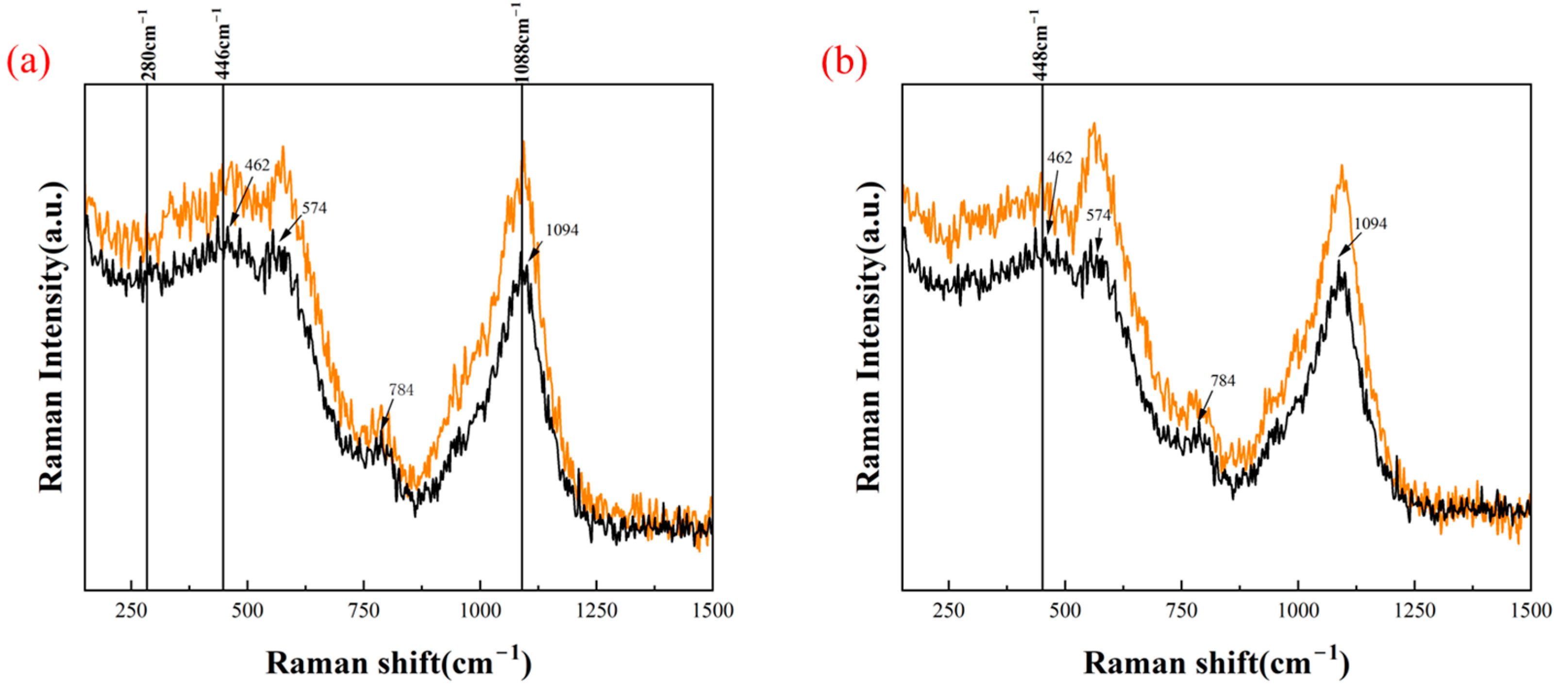
Figure 8 shows the Raman spectra of the Single Mg film and Se-MgTi (range: 100–1200 cm−1). In Figure 8a, the peaks at 1094 cm−1, 784 cm−1, 574 cm−1, and 462 cm−1 are all characteristic peaks of the glass substrate itself. The Single Mg film exhibits a peak at 446 cm−1, which is assigned to the first-order Raman vibration of MgO, and a peak at 280 cm−1 associated with oxygen vacancy defects in MgO. Additionally, the appearance of the second-order peak at 1088 cm−1 indicates that laser etching promotes the growth of MgO grains and reduces defects [57]. It is worth noting that MgO easily adsorbs water vapor in the air, and a Mg (OH)2 layer may form on the surface; its Raman peaks might be misidentified as signals of MgO [57]. Furthermore, no obvious characteristic peak of elemental Mg at 405 cm−1 was observed, indicating a low content of Mg. This result explains the reason for the improved durability of the sample—the dense and highly crystalline MgO layer hinders further oxidation.
In Figure 8b, no obvious characteristic peaks are observed at 399 cm−1, 515 cm−1, and 639 cm−1 for the Mg-Ti sample, which indicates that the content of anatase-phase TiO2 is low. However, a characteristic peak of rutile-phase TiO2 appears at 448 cm−1, which suggests that high-power laser irradiation can promote the phase transition of TiO2 from anatase to rutile [58]. The intensity of this peak is weak because most of the Ti is ablated during the etching process. Rutile titania is detrimental to transmission due to its high refractive index and absorption. Therefore, low refractive index MgO has been introduced to compensate for the former. According to effective medium theory, the nano-sized structural also minimizes the detrimental effect from this composition. Therefore, the composite enhanced transmission. Meanwhile, the ratio of the anatase phase to rutile phase increased for the Mg-Ti sample, forming a mixed crystal structure. Compared with pure anatase TiO2 thin films, the TiO2 thin films with anatase/rutile mixed crystal structure exhibit higher photocatalytic activity [59]. Consequently, this enhanced photocatalysis led to improved antifogging performance. In summary, the nano-sized structure, MgO introduction, and the mixed crystal structure simultaneously enhanced transmission and antifogging performance. The results show that a TiO2-modified layer can be prepared by laser, which is suitable for photocatalytic applications.

3.4. Optical Properties

Figure 9a demonstrates that the transmittance of Single Mg film achieved a substantial increase compared with that of reference glass, showing excellent antireflection effect, This phenomenon can be explained by the effective medium theory [60]: when the size of the micro-nano structure is smaller than the target wavelength, which is equivalent to gradient refractive indexed layer upon light propagation through, the interface impedance matches ideally, thereby significantly reducing reflection loss. The results in Figure 9b,c show that the light transmittance of all Mg-Ti samples has been improved to varying degrees compared with the reference glass. For Se-MgTi, a line spacing of 0.02 mm generally has a better antireflection effect than other line spacing groups. This may be attributed to the uniform and dense micro-nano structure, which reduced loss due to irregular large particles. Excessively wide line spacing led to insufficient ablation and excessive film residue, causing absorption loss; while an excessively narrow line spacing will result in excessive ablation and the formation of irregular large micro-nano structures, leading to scattering loss. Furthermore, the samples treated exhibited a 2% increase in light transmittance over a broad wavelength range. Through the analysis of test results obtained from multiple measurements of the same batch of samples at different times, it was confirmed that the magnitude of this transmittance improvement far exceeds the measurement error.
The calculated values of band gap were found to be ~3.60 eV for pure TiO2 thin film and for doped TiO2 films in the range from 3.2 to 3.5 eV.
The specific band gap values are presented in Table 2. The indirect band gap transition of the samples was calculated using the following Tauc equation (Equation (1)) [61].
α = A(hν − Eg)1/2
where
α = absorption coefficient.
Eg = absorption band gap.
A = constant.
The band gap determination with Tauc plot equation is shown in Figure 10. The results indicate that Mg-involvement reduced the band gap of TiO2 thin films, which was beneficial to photocatalysis and consistent with the literature [61].

3.5. Wettability Test

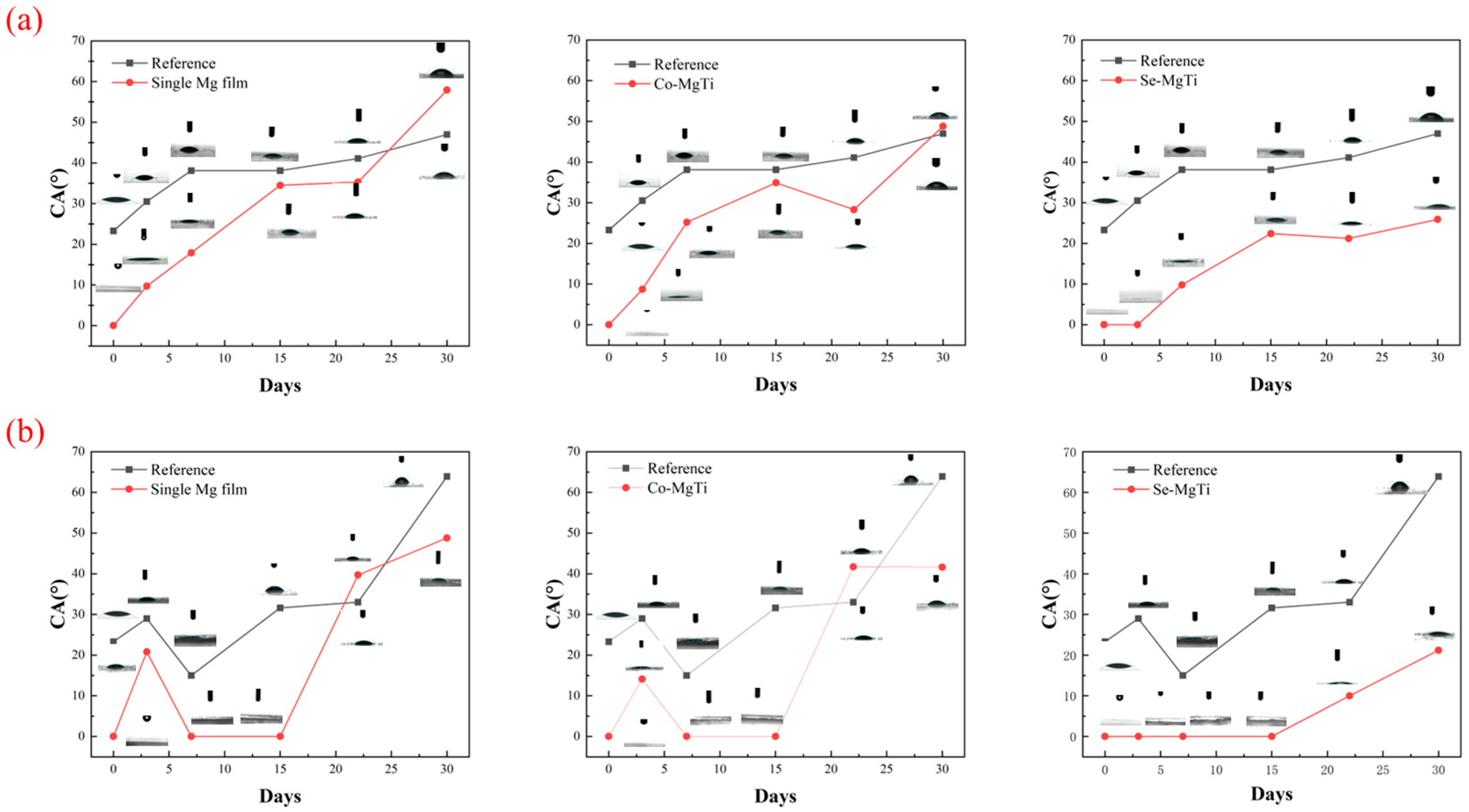
Figure 11 shows the results of the static water contact angle test, with a contact angle of 0°, indicating that the micro-nano structure with superhydrophilicity was successfully constructed on the glass surface. After the samples were placed in indoor and outdoor environments for one month (22 April–22 May), their contact angles all increased to varying degrees.
As can be seen from Figure 11a, due to the stability of the indoor environment, the contact angle increases continuously over time. It is worth noting that the contact angle of the Single Mg film and Co-MgTi increased on the third day due to the adsorption of organic substances and dust, while the contact angle of Se-MgTi began to rise after approximately 7 days of exposure. However, such changes in contact angle are generally slight and reversible. At around day 23, indoor exposure, the contact angle of the Mg-Ti sample decreased slightly, while that of the Single Mg film changed little. This may be because under sufficient light conditions, the photocatalytic effect of TiO2 decomposes organic substances on the glass surface, thereby slightly reducing the contact angle, making the contact angle of such samples always lower than that of the reference glass. Further observation shows that the contact angles of the Single Mg film and Co-MgTi were equal to that of the reference glass on day 23 and day 29, respectively, indicating that their self-cleaning effect had reached the limit; while the contact angle of Se-MgTi was always about 20° at even day 30, showing better self-cleaning ability.
As shown in Figure 11b, the complex outdoor environment caused large fluctuations in the contact angle of the samples. The singular point of the contact angle on the third day of the test is presumed to be related to the short-term increase in contact angle caused by rainfall. Since the test was conducted shortly after rainfall, a trace water film that was barely visible to the naked eye remained on the sample surface. It should be noted that this trace water film would not damage the surface structure of the film. However, the residual surface water film caused the measured contact angle to fail to reflect the properties of the fully exposed surface, and the increase in contact angle was essentially the result of the combined effect of the partially exposed surface and the water film. Subsequently, under the influence of environmental factors such as sunlight due to photocatalysis, the contact angle on the film surface would gradually return to 0°. For the initial 15 days, the samples still maintained a contact angle of 0°. After 15 days, the contact angles of all samples increased to varying degrees, among which the contact angle of Se-MgTi was significantly lower than that of the Single Mg film and Co-MgTi. The performance of all treated samples was better than the reference glass before day 23, and Se-MgTi performed the most prominently. The underperformance of the Mg sample may be due to a lack of photocatalytic titania. While the performance of Co-MgTi was accounted for by the low roughness and associated low amount of photocatalytic titania.
Figure 12 presents the contact angles of treated glass and the reference after a water spray cleaning. As shown in Figure 12a,b, the contact angle of the reference glass showed no obvious change after cleaning, while the contact angles of glass treated with different processes all exhibited a significant decreasing trend. Among them, after water spraying treatment, the contact angle of the Single Mg drops from approximately 50° to around 20°. The introduction of Ti further enhanced the hydrophilicity, and this optimization effect was manifested in both indoor and outdoor environments: the contact angle of Co-MgTi after a water spray cleaning was about 16°; while Se-MgTi performed even better, with the contact angle dropping below 10°, which indicates that this sample still maintained superhydrophilic characteristics.

3.6. Self-Cleaning Performance Test

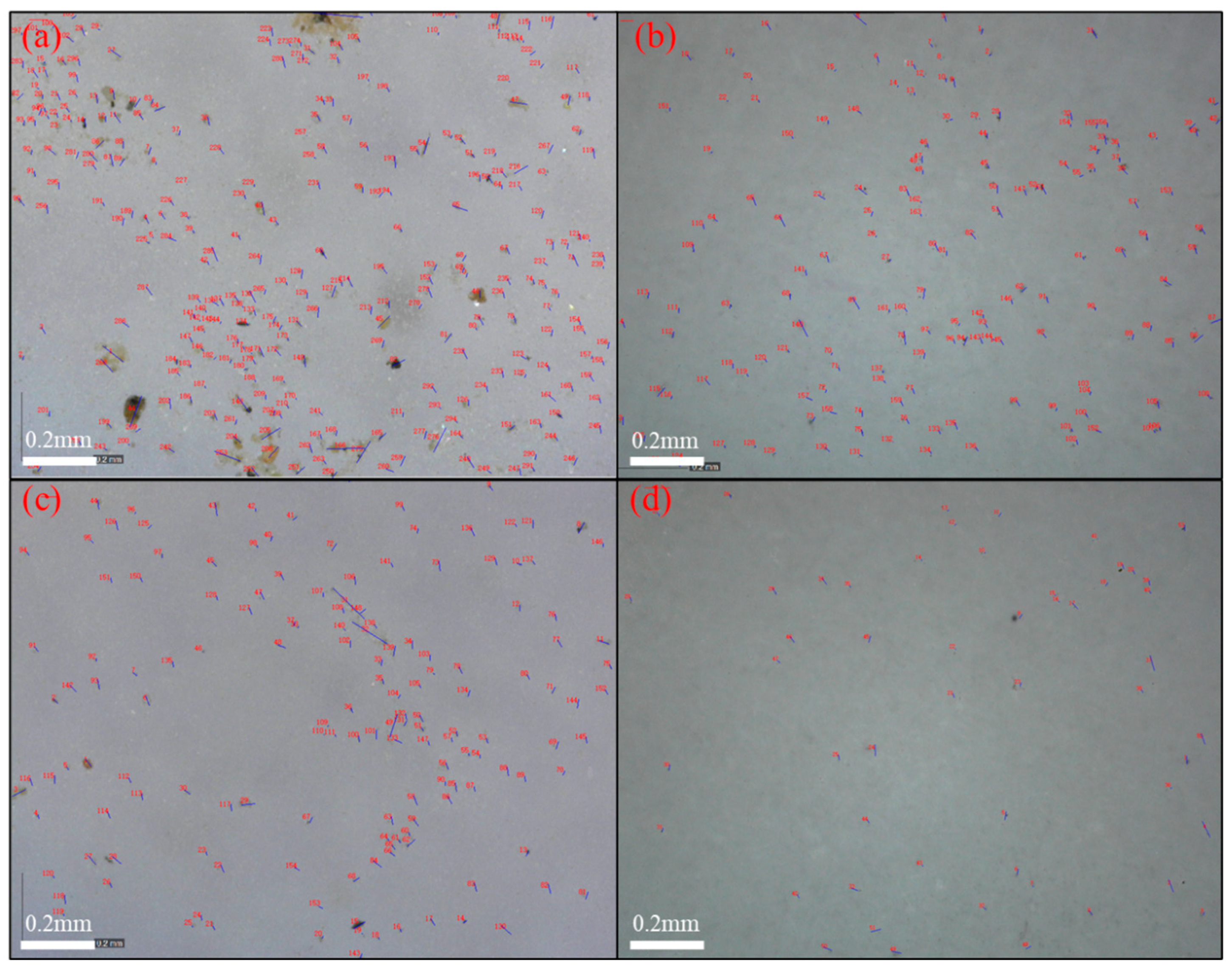
Figure 13a shows the dust particle distribution on the reference glass substrate, displaying both significant size heterogeneity and high surface coverage density. Subsequent water spray treatment substantially decreased the particulate contamination, although considerable residual particles remained observable (Figure 13b). In comparison, the optimal sample (Figure 13c) had considerably fewer particles before spraying. In the meantime, it demonstrated markedly improved dust removal efficiency by a single spray. Most notably, under identical spray treatment conditions, the optimal sample surface exhibited near-complete dust removal, in striking contrast to the reference glass. A single water spray removed 67% of the dust from the optimal sample surface, compared with only 26% for the reference sample. These results clearly demonstrate enhanced self-cleaning capability of the treated surfaces.
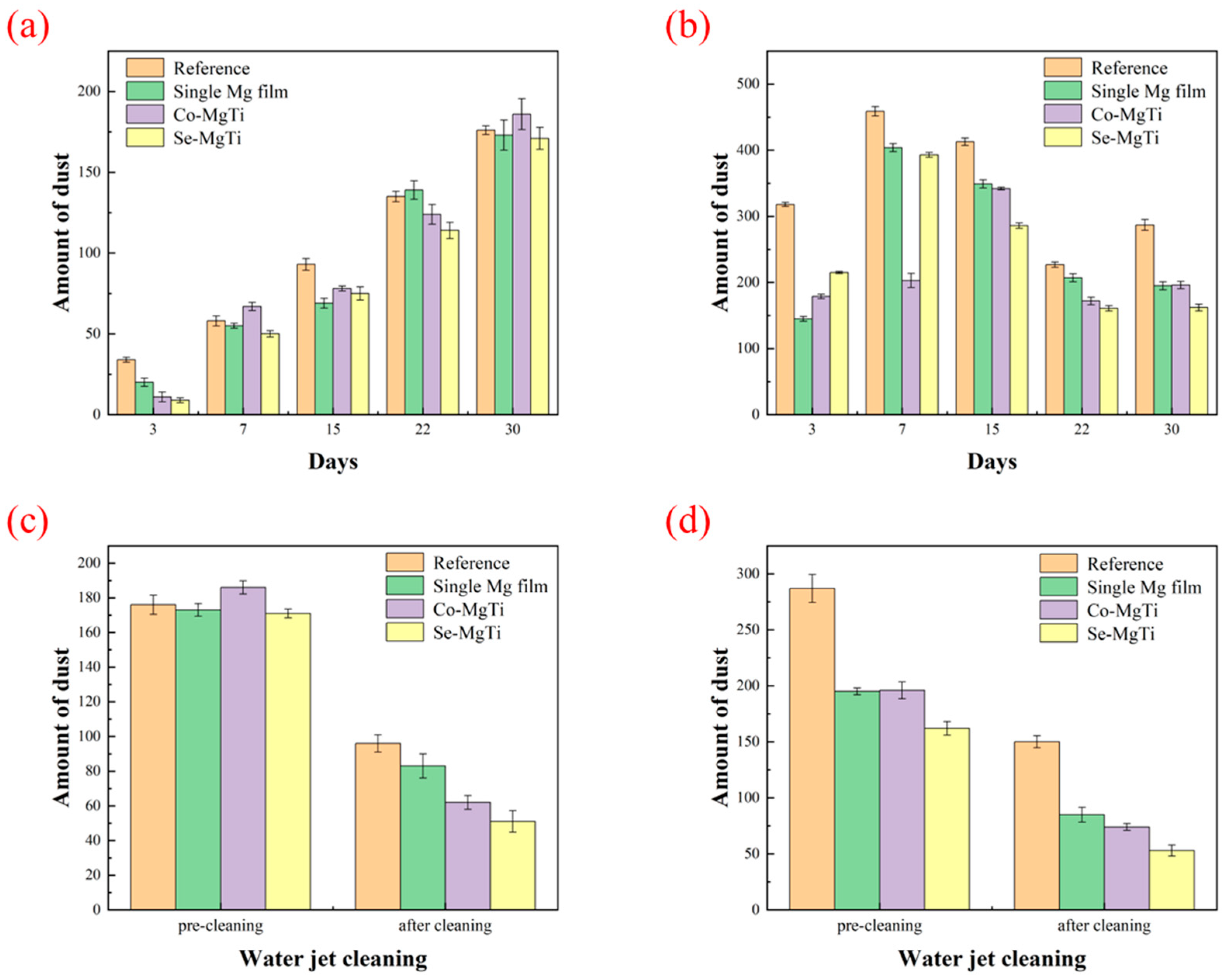
Figure 14 shows the dust particles distribution on the samples under different conditions. Figure 14a shows that the amount of dust absorbed on the glass surface in an indoor environment increased with exposure time. Initially, the amount of dust adsorbed on the treated glass surface was generally lower than that of the reference glass, which indicates that the micro- and nanostructures formed by the treatment can reduce the adsorption of the dust; however, due to the limitation of the static environment, it is difficult for the adsorbed dust to detach from the glass surface by itself, which led to the accumulation of the total amount of dust. After 23 days, the difference in dust adsorption between the treatment group and the reference glass gradually narrowed, suggesting that its dust resistance ability had reached its limit. It is worth noting that the amount of dust in the Se-MgTi glass was always lower than that of the reference glass, which showed a long-lasting anti-dust performance. Figure 14b shows that the complex outdoor environment resulted in significant fluctuations in glass dust adsorption, which is related to the effect of natural factors, such as rainfall and sunlight, on the removal of dust during the period. Despite the environmental fluctuations, the amount of dust adsorbed on the surface of the treated glass was always lower than that of the reference glass. The size of dust adsorbed by the glass in the outdoor environment was mainly concentrated within 0.1 mm, while the larger particles were easily removed by rainfall. Figure 14c,d shows the quantitative analysis results of dust particle removal by a single water spray. The number of dust particles on the surface of the sample was significantly reduced after a spray rinse and 3 h of natural drying. In the indoor environment, the dust removal rate of the best sample (71.18%) was significantly higher than that of the reference glass (45.45%), the Single Mg film (52.05%), and Co-MgTi (66.67%). While in the outdoor environment, Se-MgTi also showed excellent dust removal effect, with a higher removal rate (67.28%) than that of the reference glass (47.74%), Single Mg film (57.07%), and Co-MgTi (62.24%). This result demonstrated the excellent self-cleaning property of the treated sample surface.

3.7. Antifog Performance Test

The test results in Figure 15 show that within the one-month test period, the antifogging performance of the glass subjected to different treatments was significantly better than that of the reference glass. Moreover, the antifogging performance of the samples did not show any attenuation, indicating good stability. In the antifog test, the residual amount of water droplets on the surface of the treated glass was significantly less than that on ordinary glass, which confirms that it can achieve excellent antifogging and light transmission performance with rapid water spreading to the edge and evaporation. The drying time of water on the surface of the treated glass is significantly shorter than that of the reference glass. The drying time of Se-MgTi is approximately 1–2 min, while the reference sample takes about 5 min. This fast water spreading and evaporation reduced reflection, thereby endowing the glass with good antifogging performance and light transmission characteristics [62].

3.8. Aging Test

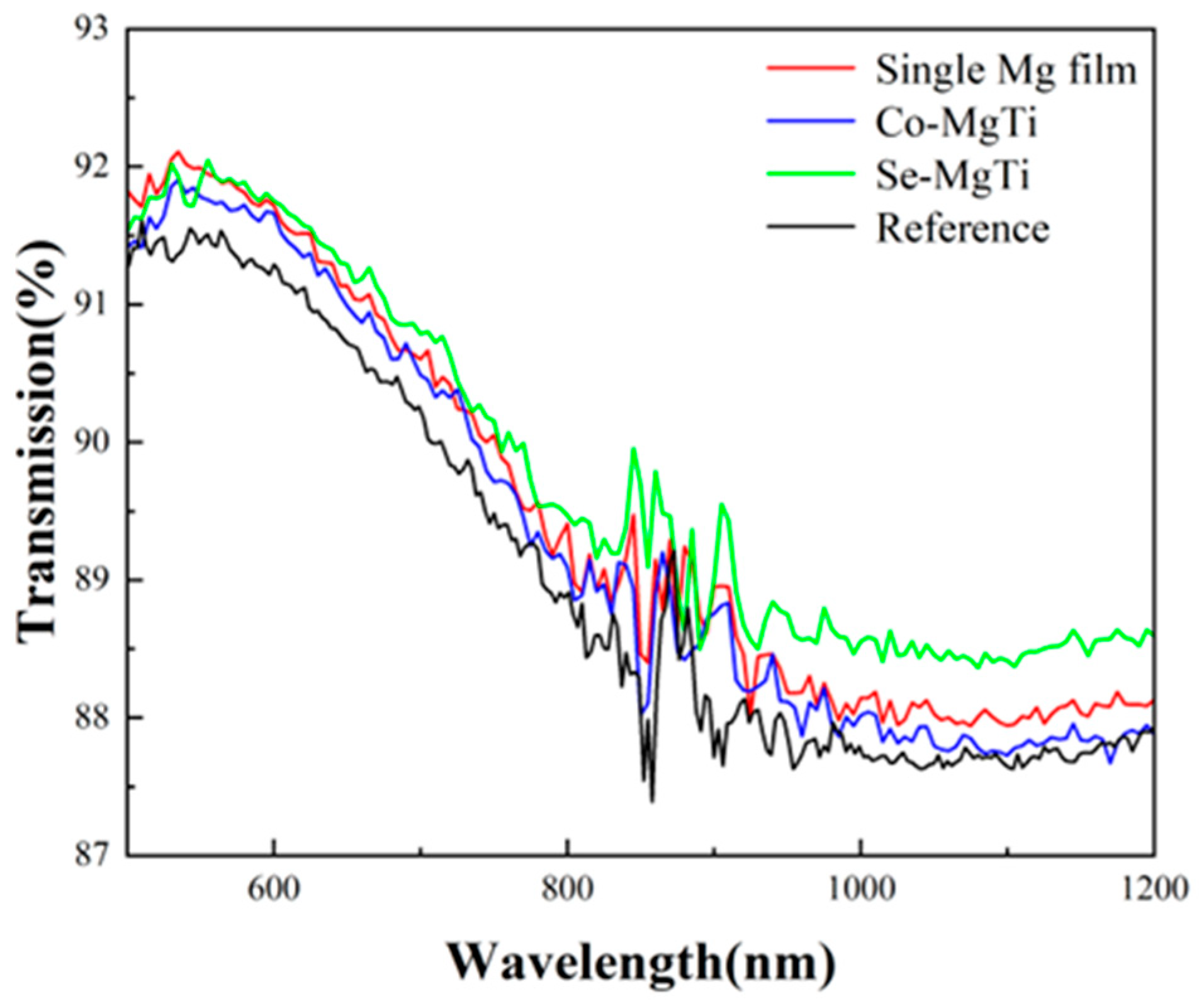
As shown in Figure 16, the transmittance of the sample after 60 h of UV irradiation still shows an increase of 0.5%–2% compared with the reference glass, which confirms its stable anti-aging performance.
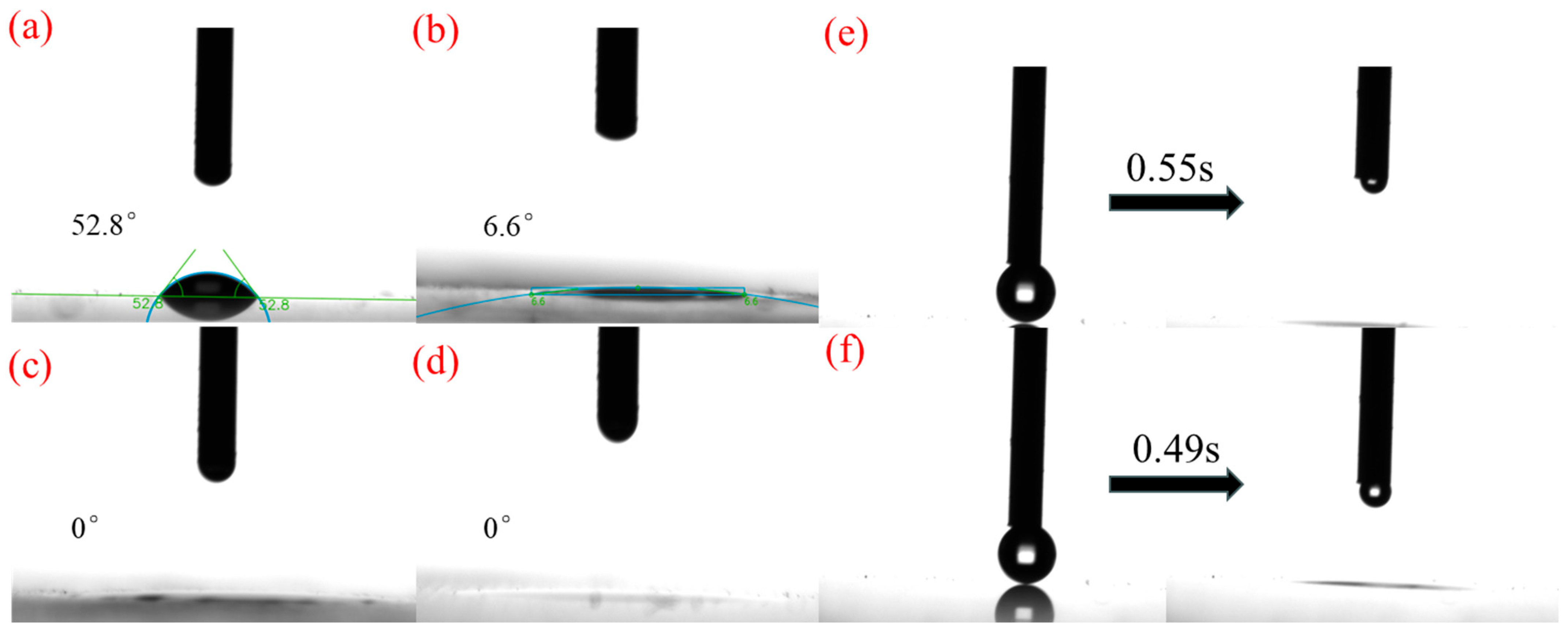
Figure 17 shows the contact angles of the samples after the UV aging test. Compared with samples without UV irradiation, the contact angle of the reference glass shows no obvious change. The contact angle of Single Mg increased to 6.6°, while the contact angles of the Co-MgTi and Se-MgTi samples were stably maintained at 0° after UV irradiation. It is worth noting that the water droplet spreading-out time after UV irradiation testing was shorter than that of the unirradiated samples. The results indicate that all three samples exhibit excellent hydrophilicity and anti-aging performance.

3.9. Photocatalytic Degradation Test of MO

The degradation rate of MO was calculated according to the formula (Equation (2)) [29], as shown in Figure 18.
% degradation = A 0 A t A 0
Here, A0 denotes the initial absorbance of MO, At denotes the absorbance of MO at time t.
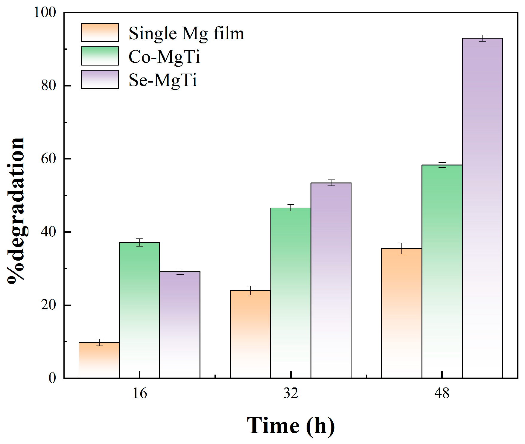
Calculation results are shown in Figure 18. It indicates that Se-MgTi exhibited the best performance after 48 h of UV light irradiation, with the MO degradation rate reaching 90%. Mg increased active O species, such as O vacancy, and reduced the bandgap of titania, together with dense nanoparticles distribution, which enhanced photocatalysis, accelerating decomposition of MO.

3.10. Abrasion Resistance Test

As shown in Figure 19a, except for Se-MgTi, the contact angles of other samples increased with the number of friction cycles. The decrease in contact angle after 6 friction cycles is presumably related to the scratches caused on the glass by the 60-mesh coarse-grained sandpaper. The contact angle of Se-MgTi remained unchanged throughout the process, indicating that its film layer has strong adhesion to the glass surface, and thus exhibits good wear resistance. Se-MgTi demonstrated far less scratches than the reference glass after 10 cycles of abrasion resistance test, as shown in Figure 19b,c.

4. Conclusions

In this study, a facile and rapid laser deposition technique was employed to coat glass substrates with a photocatalytic layer, followed by laser etching to create hierarchical micro- and nanostructures through selective removal of the photocatalyst. The synergistic effects of the engineered surface roughness and residual photocatalytic coating significantly enhanced surface hydrophilicity, endowing the material with superhydrophilicity, antifogging, and self-cleaning functionalities.
The influence of laser processing parameters—including frequency and scanning line spacing—on the surface microstructure was systematically investigated. During laser etching, overly narrow line spacing induced over-etching and irregular surface topography, which detrimentally affected hydrophilicity, while overly wide spacing led to incomplete etching and impaired light transmission. Similarly, excessively high frequency caused over-etching and diminished residual photocatalyst particles, reducing photocatalytic performance, whereas excessively low frequency yielded irregularly large residual particles and increased optical losses.
The optimal parameter combination for the single Mg film process was determined as follows: laser scanning speed of 2 m/s, power density of 50%, frequency of 100 kHz, deposition line spacing of 0.5 mm, and etching line spacing of 0.03 mm. For the Se-MgTi and Co-MgTi processes, the optimal etching line spacing was refined to 0.02 mm. Among the tested variants, the Se-MgTi coating exhibited the most robust antifogging and self-cleaning performance. Both laboratory and outdoor evaluations demonstrated that the Se-MgTi-coated glass achieved exceptional and durable self-cleaning and antifogging properties compared to unmodified controls. The water contact angle of the treated surfaces decreased dramatically from 44° to 0° (complete wetting) and remained stable after 15 days of outdoor exposure. The modified surfaces also exhibited significantly reduced dust accumulation and superior one-step spray-cleaning efficiency relative to the reference. Furthermore, the treated samples showed a broadband light transmittance enhancement of 2% due to the antireflective effect of the etched structures.
To the best of our knowledge, this work represents one of the few reports on laser processing in an air-based strategy that simultaneously confers durable indoor and outdoor superhydrophilicity, antireflective behavior, antifogging, and self-cleaning properties. These multifunctional attributes arise from the synergistic interplay between the laser-generated hierarchical surface topography and the residual photocatalytic coating.

Author Contributions

H.C.: Writing—review & editing, Supervision, Resources, Methodology, Funding acquisition, Formal analysis, Data curation, Conceptualization. Z.Z.: Writing–original draft, Software, Resources, Investigation, Formal analysis, Data curation. F.Z.: Software, Investigation. Y.G.: Software, Investigation. L.C.: Software, Investigation. J.L.: Software, Investigation. Y.W.: Software, Investigation. C.S.: Software, Investigation. All authors have read and agreed to the published version of the manuscript.

Funding

This research was funded by Youth Taishan Scholar grant number tsqn201909128.

Data Availability Statement

Data will be made available on request.

Conflicts of Interest

The authors declare no conflict of interest.

References

  1. de Araujo, C.B.; Kassab, L.R.P.; da Silva, D.M. Optical properties of glasses and glass-ceramics for optical amplifiers, photovoltaic devices, color displays, optical limiters, and Random Lasers. Opt. Mater. 2022, 131, 112648. [Google Scholar] [CrossRef]
  2. Talu, S.; Yadav, R.P.; Sik, O.; Sobola, D.; Dallaev, R.; Solaymani, S.; Man, O. How topographical surface parameters are correlated with CdTe monocrystal surface oxidation. Mater. Sci. Semicond. Process. 2018, 85, 15–23. [Google Scholar] [CrossRef]
  3. He, X.; Punpongjareorn, N.; Wu, C.Y.; Davydov, I.A.; Yang, D.S. Ultrafast Carrier Dynamics of CdTe: Surface Effects. J. Phys. Chem. C 2016, 120, 9350–9356. [Google Scholar] [CrossRef]
  4. Zaihidee, F.M.; Mekhilef, S.; Seyedmahmoudian, M.; Horan, B. Dust as an unalterable deteriorative factor affecting PV panel’s efficiency: Why and how. Renew. Sustain. Energy Rev. 2016, 65, 1267–1278. [Google Scholar] [CrossRef]
  5. Nayshevsky, I.; Xu, Q.F.; Barahman, G.; Lyons, A.M. Fluoropolymer coatings for solar cover glass: Anti-soiling mechanisms in the presence of dew. Sol. Energy Mater. Sol. Cells 2020, 206, 110281. [Google Scholar] [CrossRef]
  6. Ilse, K.; Werner, M.; Naumann, V.; Figgis, B.W.; Hagendorf, C.; Bagdahn, J. Microstructural analysis of the cementation process during soiling on glass surfaces in arid and semi-arid climates. Phys. Status Solidi-Rapid Res. Lett. 2016, 10, 525–529. [Google Scholar] [CrossRef]
  7. Kazmerski, L.L.; Diniz, A.S.A.C.; Maia, C.B.; Viana, M.M.; Costa, S.C.; Brito, P.P.; Campos, C.D.; Macheto Neto, L.V.; Hanriot, S.d.M.; de Oliveira Cruz, L.R. Fundamental Studies of Adhesion of Dust to PV Module Surfaces: Chemical and Physical Relationships at the Microscale. IEEE J. Photovolt. 2016, 6, 719–729. [Google Scholar] [CrossRef]
  8. Sarver, T.; Al-Qaraghuli, A.; Kazmerski, L.L. A comprehensive review of the impact of dust on the use of solar energy: History, investigations, results, literature, and mitigation approaches. Renew. Sustain. Energy Rev. 2013, 22, 698–733. [Google Scholar] [CrossRef]
  9. Dalawai, S.P.; Aly, M.A.S.; Latthe, S.S.; Xing, R.; Sutar, R.S.; Nagappan, S.; Ha, C.-S.; Sadasivuni, K.K.; Liu, S. Recent Advances in durability of superhydrophobic self-cleaning technology: A critical review. Prog. Org. Coat. 2020, 138, 105381. [Google Scholar] [CrossRef]
  10. Wang, X.-S.; Cui, S.-W.; Zhou, L.; Xu, S.-H.; Sun, Z.-W.; Zhu, R.-Z. A generalized Young’s equation for contact angles of droplets on homogeneous and rough substrates. J. Adhes. Sci. Technol. 2014, 28, 161–170. [Google Scholar] [CrossRef]
  11. Kim, D.; Pugno, N.M.; Ryu, S. Wetting theory for small droplets on textured solid surfaces. Sci. Rep. 2016, 6, 37813. [Google Scholar] [CrossRef]
  12. Zhang, Y.; Dong, Z.; Li, C.; Du, H.; Fang, N.X.; Wu, L.; Song, Y. Continuous 3D printing from one single droplet. Nat. Commun. 2020, 11, 4685. [Google Scholar] [CrossRef] [PubMed]
  13. Yang, L.; Luo, X.; Chang, W.; Tian, Y.; Wang, Z.; Gao, J.; Cai, Y.; Qin, Y.; Duxbury, M. Manufacturing of anti-fogging super-hydrophilic microstructures on glass by nanosecond laser. J. Manuf. Process. 2020, 59, 557–565. [Google Scholar] [CrossRef]
  14. Zhi, J.; Zhang, L.-Z. Durable superhydrophobic surface with highly antireflective and self-cleaning properties for the glass covers of solar cells. Appl. Surf. Sci. 2018, 454, 239–248. [Google Scholar] [CrossRef]
  15. Duran, I.R.; Laroche, G. Current trends, challenges, and perspectives of anti-fogging technology: Surface and material design, fabrication strategies, and beyond. Prog. Mater. Sci. 2019, 99, 106–186. [Google Scholar] [CrossRef]
  16. Blossey, R. Self-cleaning surfaces—Virtual realities. Nat. Mater. 2003, 2, 301–306. [Google Scholar] [CrossRef]
  17. Xu, F.; Wang, T.; Bohling, J.; Maurice, A.M.; Chen, H.; Wu, L.; Zhou, S. Insight into the dependence of dirt adsorption/desorption on the surface wetting behavior of TiO2-based nanocomposite coatings. Prog. Org. Coat. 2019, 131, 137–144. [Google Scholar] [CrossRef]
  18. Lu, X.; Wang, Z.; Yang, X.; Xu, X.; Zhang, L.; Zhao, N.; Xu, J. Antifogging and antireflective silica film and its application on solar modules. Surf. Coat. Technol. 2011, 206, 1490–1494. [Google Scholar] [CrossRef]
  19. Huang, Y.; Hu, Y.; Zhu, C.; Zhang, F.; Li, H.; Lu, X.; Meng, S. Long-Lived Multifunctional Superhydrophobic Heterostructure Via Molecular Self-Supply. Adv. Mater. Interfaces 2016, 3, 1500727. [Google Scholar] [CrossRef]
  20. Hwang, G.B.; Patir, A.; Allan, E.; Nair, S.P.; Parkin, I.P. Superhydrophobic and White Light-Activated Bactericidal Surface through a Simple Coating. Acs Appl. Mater. Interfaces 2017, 9, 29002–29009. [Google Scholar] [CrossRef]
  21. Jeung, Y.; Yong, K. Underwater superoleophobicity of a superhydrophilic surface with unexpected drag reduction driven by electrochemical water splitting. Chem. Eng. J. 2020, 381, 122734. [Google Scholar] [CrossRef]
  22. Huang, S.; Ras, R.H.A.; Tian, X. Antifouling membranes for oily wastewater treatment: Interplay between wetting and membrane fouling. Curr. Opin. Colloid Interface Sci. 2018, 36, 90–109. [Google Scholar] [CrossRef]
  23. Mi, L.; Wang, Y.; Fang, X.; Qi, X.; Chen, L.; Cui, H. Laser-fabricated core-shell Cu/Zn-based photocatalytic films with superhydrophilic self-cleaning properties. J. Alloys Compd. 2025, 1026, 180422. [Google Scholar] [CrossRef]
  24. Armakovic, S.J.; Savanovic, M.M.; Armakovic, S. Titanium Dioxide as the Most Used Photocatalyst for Water Purification: An Overview. Catalysts 2023, 13, 26. [Google Scholar] [CrossRef]
  25. Shayegan, Z.; Lee, C.-S.; Haghighat, F. TiO2 photocatalyst for removal of volatile organic compounds in gas phase—A review. Chem. Eng. J. 2018, 334, 2408–2439. [Google Scholar] [CrossRef]
  26. Yao, L.; He, J. Facile dip-coating approach to fabrication of mechanically robust hybrid thin films with high transmittance and durable superhydrophilicity. J. Mater. Chem. A 2014, 2, 6994–7003. [Google Scholar] [CrossRef]
  27. Piispanen, M.; Hupa, L. Comparison of self-cleaning properties of three titania coatings on float glass. Appl. Surf. Sci. 2011, 258, 1126–1131. [Google Scholar] [CrossRef]
  28. Zhang, Y.; Zhang, S.; Wu, S. Room-temperature fabrication of TiO2-PHEA nanocomposite coating with high transmittance and durable superhydrophilicity. Chem. Eng. J. 2019, 371, 609–617. [Google Scholar] [CrossRef]
  29. Cui, H.; Fang, X.; Qi, X.; Wang, Y.; Wang, H.; Zhai, Z.; Zhang, F.; Hu, Q.; Liu, J. Laser-fabricated core-shell Ti/W based photocatalytic films with superhydrophilic self-cleaning properties. Surf. Interfaces 2025, 61, 106147. [Google Scholar] [CrossRef]
  30. Zhong, H.; Liu, X.; Yu, B.; Zhou, S. Fast UV-Curable Zwitter-Wettable Coatings with Reliable Antifogging/Frost-Resisting Performances. Biomimetics 2022, 7, 162. [Google Scholar] [CrossRef]
  31. Wang, P.; Qi, X.; Fang, X.; Teng, C.; Guo, Y.; Liu, C.; Chen, X.; Cui, H. Durable self-cleaning anti-fog and antireflective micro-nano structures fabricated by laser marker ablation of Si coated glass. Ceram. Int. 2024, 50, 31402–31417. [Google Scholar] [CrossRef]
  32. Cui, H.; Teng, C.; Zhao, Y.; Wang, P.; Guo, Y.; Qi, X. Durable self-cleaning antireflective and antifog Al micro-nano structure on glass by laser marker ablation. Opt. Mater. 2024, 147, 114675. [Google Scholar] [CrossRef]
  33. Akimov, Y.A. Mie scattering theory: A review of physical features and limitations. arXiv 2024, arXiv:2401.04146. [Google Scholar] [CrossRef]
  34. Guo, L.; Huang, J.; Xue, L.; Zhang, R. Research on the arc stability of dry hyperbaric GMAW from the perspective of arc energy and electrical conductivity. J. Manuf. Process. 2025, 138, 14–23. [Google Scholar] [CrossRef]
  35. Abildina, A.A.; Kurbatov, A.P.; Bakhytzhan, Y.G.; Jumanova, R.Z.; Argimbayeva, A.M.; Avchukir, K.; Rakhymbay, G.S. Corrosion behavior of magnesium in aqueous sulfate-containing electrolytes. J. Magnes. Alloys 2023, 11, 2125–2141. [Google Scholar] [CrossRef]
  36. Aghion, E. Biodegradable Metals. Metals 2018, 8, 804. [Google Scholar] [CrossRef]
  37. She, J.; Chen, J.; Xiong, X.; Yang, Y.; Peng, X.; Chen, D.; Pan, F. Research advances of magnesium and magnesium alloys globally in 2023. J. Magnes. Alloys 2024, 12, 3441–3475. [Google Scholar] [CrossRef]
  38. Yang, Y.; Xiong, X.M.; Chen, J.; Peng, X.D.; Chen, D.L.; Pan, F.S. Research advances of magnesium and magnesium alloys worldwide in 2022. J. Magnes. Alloys 2023, 11, 2611–2654. [Google Scholar] [CrossRef]
  39. Feng, L.; Zhu, Y.; Wang, J.; Shi, X. One-step hydrothermal process to fabricate superhydrophobic surface on magnesium alloy with enhanced corrosion resistance and self-cleaning performance. Appl. Surf. Sci. 2017, 422, 566–573. [Google Scholar] [CrossRef]
  40. Ishizaki, T.; Hieda, J.; Saito, N.; Saito, N.; Takai, O. Corrosion resistance and chemical stability of super-hydrophobic film deposited on magnesium alloy AZ31 by microwave plasma-enhanced chemical vapor deposition. Electrochim. Acta 2010, 55, 7094–7101. [Google Scholar] [CrossRef]
  41. Kiahosseini, S.R.; Afshar, A.; Larijani, M.M.; Yousefpour, M. Structural and corrosion characterization of hydroxyapatite/zirconium nitride-coated AZ91 magnesium alloy by ion beam sputtering. Appl. Surf. Sci. 2017, 401, 172–180. [Google Scholar] [CrossRef]
  42. Peng, M.K.; Zhang, X.D.; Xiao, X.; Dong, M.J.; Zhao, G.W.; Liu, P.; Chen, Y.S.; Wang, C.H. Polyelectrolytes fabrication on magnesium alloy surface by layer-by-layer assembly technique with antiplatelet adhesion and antibacterial activities. J. Coat. Technol. Res. 2019, 16, 857–868. [Google Scholar] [CrossRef]
  43. Yeganeh, M.; Mohammadi, N. Superhydrophobic surface of Mg alloys: A review. J. Magnes. Alloys 2018, 6, 59–70. [Google Scholar] [CrossRef]
  44. Syafiq, A.; Balakrishnan, V.; Abd Rahim, N.A. Durable self-cleaning nano-titanium dioxide superhydrophilic coating with anti-fog property. Pigment Resin Technol. 2024, 53, 261–270. [Google Scholar] [CrossRef]
  45. Wang, X.; Ding, H.; Lv, G.C.; Zhou, R.; Ma, R.X.; Hou, X.F.; Zhang, J.M.; Li, W. Fabrication of superhydrophilic self-cleaning SiO2-TiO2 coating and its photocatalytic performance. Ceram. Int. 2022, 48, 20033–20040. [Google Scholar] [CrossRef]
  46. Chinthala, M.; Balakrishnan, A.; Venkataraman, P.; Gowtham, V.M.; Polagani, R.K. Synthesis and applications of nano-MgO and composites for medicine, energy, and environmental remediation: A review. Environ. Chem. Lett. 2021, 19, 4415–4454. [Google Scholar] [CrossRef]
  47. Liu, C.L.; Fang, X.L.; Chen, X.J.; Qi, X.W.; Teng, C.; Xie, X.Y.; Wang, Y.F.; Lu, G.X.; Chen, L.Z.; Mi, L.F.; et al. Flash regeneration of superhydrophilicity and antifog performance of laser induced molybdenum based micro-nano structures by flame treatment. J. Manuf. Process. 2025, 141, 169–180. [Google Scholar] [CrossRef]
  48. Cui, H.; Fang, X.; Qi, X.; Wang, Y.; Wang, H.; Li, C. Nature-inspired wettability-mixed titanium surface for efficient fog collection. Appl. Mater. Today 2025, 44, 102792. [Google Scholar] [CrossRef]
  49. Pescheux, A.C.; Raccurt, O.; Bourdon, D.; Le Baron, E. Accelerated aging tests and characterizations of innovated anti-soiling coatings for solar receiver glasses. Mater. Chem. Phys. 2020, 256, 123646. [Google Scholar] [CrossRef]
  50. Xie, X.; Qi, X.; Chen, X.; Cui, H. Durable self-cleaning anti-fog and antireflective titanium-based micro-nano structures on glass by laser marker ablation. Surf. Interfaces 2024, 51, 104644. [Google Scholar] [CrossRef]
  51. Vorobyev, A.Y.; Guo, C. Direct femtosecond laser surface nano/microstructuring and its applications. Laser Photonics Rev. 2013, 7, 385–407. [Google Scholar] [CrossRef]
  52. Hauschwitz, P.; Jagdheesh, R.; Rostohar, D.; Brajer, J.; Kopecek, J.; Jiricek, P.; Houdkova, J.; Mocek, T. Hydrophilic to ultrahydrophobic transition of Al 7075 by affordable ns fiber laser and vacuum processing. Appl. Surf. Sci. 2020, 505, 144523. [Google Scholar] [CrossRef]
  53. He, W.; Yao, P.; Chu, D.; Sun, H.; Lai, Q.; Wang, Q.; Wang, P.; Qu, S.; Huang, C. Controllable hydrophilic titanium surface with micro-protrusion or micro-groove processed by femtosecond laser direct writing. Opt. Laser Technol. 2022, 152, 108082. [Google Scholar] [CrossRef]
  54. Guo, S.; Liu, M.D.; You, L.M.; Cheng, G.; Li, J.; Zhou, K. Oxygen vacancy induced peroxymonosulfate activation by Mg-doped Fe2O3 composites for advanced oxidation of organic pollutants. Chemosphere 2021, 279, 130482. [Google Scholar] [CrossRef] [PubMed]
  55. Nithya, N.; Gopi, S.; Bhoopathi, G. An Amalgam of Mg-Doped TiO2 Nanoparticles Prepared by Sol-Gel Method for Effective Antimicrobial and Photocatalytic Activity. J. Inorg. Organomet. Polym. Mater. 2021, 31, 4594–4607. [Google Scholar] [CrossRef]
  56. Yang, Z.; Liu, X.P.; Tian, Y.L. Insights into the wettability transition of nanosecond laser ablated surface under ambient air exposure. J. Colloid Interface Sci. 2019, 533, 268–277. [Google Scholar] [CrossRef]
  57. Dekermenjian, M.; Ruediger, A.P.; Merlen, A. Raman spectroscopy investigation of magnesium oxide nanoparticles. Rsc Adv. 2023, 13, 26683–26689. [Google Scholar] [CrossRef]
  58. Kernazhitsky, L.; Shymanovska, V.; Gavrilko, T.; Naumov, V.; Fedorenko, L.; Kshnyakin, V.; Baran, J. Room temperature photoluminescence of anatase and rutile TiO2 powders. J. Lumin. 2014, 146, 199–204. [Google Scholar] [CrossRef]
  59. Cao, Y.Q.; Long, H.J.; Chen, Y.M.; Cao, Y.A. Photocatalytic Activity of TiO2 Films with Rutile/Anatase Mixed Crystal Structures. Acta Phys. -Chim. Sin. 2009, 25, 1088–1092. [Google Scholar]
  60. Liu, B.-T.; Yeh, W.-D. Reflective properties of nanoparticle-arrayed surfaces. Thin Solid Film. 2010, 518, 6015–6021. [Google Scholar] [CrossRef]
  61. Kumar, M.; Gupta, A.K.; Kumar, D. Mg-doped TiO2 thin films deposited by low cost technique for CO gas monitoring. Ceram. Int. 2016, 42, 405–410. [Google Scholar] [CrossRef]
  62. He, X.; Li, G.; Zhang, Y.; Lai, X.; Zhou, M.; Xiao, L.; Tang, X.; Hu, Y.; Liu, H.; Yang, Y.; et al. Bioinspired functional glass integrated with multiplex repellency ability from laser-patterned hexagonal texturing. Chem. Eng. J. 2021, 416, 129113. [Google Scholar] [CrossRef]
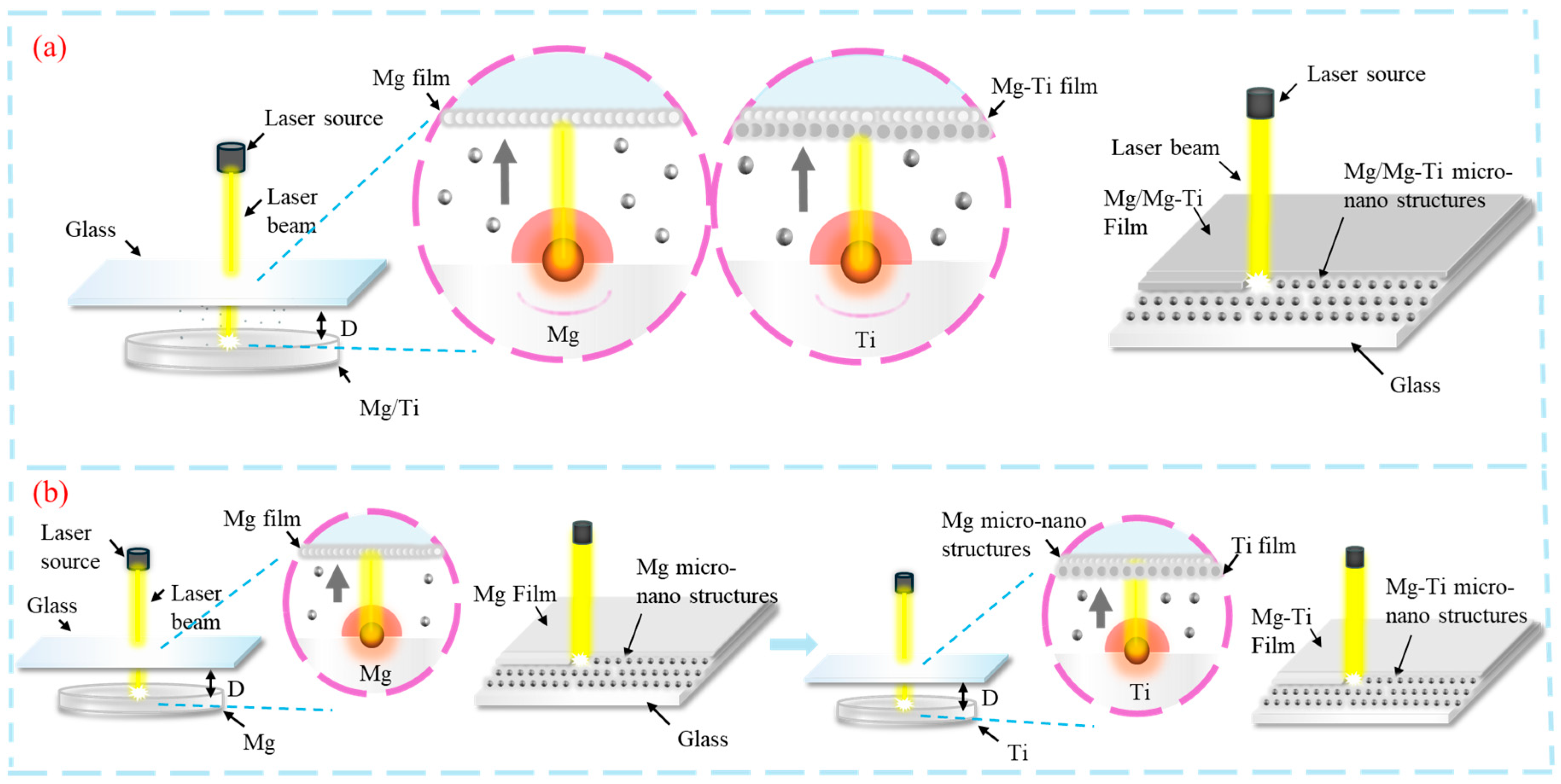
Figure 1. Schematic diagram of material deposition etching (a) Single Mg film/Co-MgTi process diagram (b) Se-MgTi process diagram.
Coatings 15 01214 g001
Figure 2. SEM images of Single Mg film at different frequencies with line spacing of 0.03 mm (a) 20 kHz (b) 50 kHz (c) 100 kHz (d) 200 kHz.
Coatings 15 01214 g002
Figure 3. SEM images of Single Mg film with different line spacing at a frequency of 100 kHz (a) 0.01 mm (b) 0.02 mm (c) 0.03 mm (d) 0.04 mm.
Coatings 15 01214 g003
Figure 4. SEM image of Mg-Ti sample with frequency of 100 kHz and line spacing of 0.03 mm (a) Co-MgTi (b) Se-MgTi.
Coatings 15 01214 g004
Figure 5. EDS mapping images of Se-MgTi processed at a line spacing of 0.03 mm and frequency of 100 kHz (a) Mg (b) Ti (c) O.
Coatings 15 01214 g005
Figure 6. Single Mg film, Co-MgTi, and Se-MgTi samples: Confocal images of surface roughness (Sa) at line spacings of 0.01–0.04 mm (a) Single Mg film ((a1a4) line spacings: 0.01–0.04 mm) (b) Co-MgTi ((b1b4) line spacings: 0.01–0.04 mm) (c) Se-MgTi ((c1c4) line spacings: 0.01–0.04 mm).
Coatings 15 01214 g006
Figure 7. XPS spectra of samples Mg and Se-MgTi (a) XPS survey spectrum ((a1): Single Mg film (a2): Se-MgTi) (b) C1s of Single Mg film and Se-MgTi (c) Ti2p of Se-MgTi (d) Mg1s ((d1): Single Mg film, (d2): Se-MgTi) (e) O1s ((e1): Single Mg film, (e2): Se-MgTi).
Coatings 15 01214 g007
Figure 8. Raman spectra of laser-processed sample and the reference (The black lines are for reference glass) (a) Single Mg film (b) Mg-Ti sample.
Coatings 15 01214 g008
Figure 9. Transmission of laser-processed samples at different line spacing and reference (a) Single Mg film (b) Co-MgTi (c) Se-MgTi.
Coatings 15 01214 g009
Figure 10. Tauc Plots of differently treated samples (a) Single Ti film (b) Co-MgTi (c) Se-MgTi.
Coatings 15 01214 g010
Figure 11. Temporal evolution of contact angles (a) indoor samples (b) outdoor samples.
Coatings 15 01214 g011
Figure 12. Contact angles of the same batch of samples that had undergone one-month indoor/outdoor testing, measured before and after a single water spray cleaning (a) Indoor (b) Outdoor.
Coatings 15 01214 g012
Figure 13. The dust particle distribution images on samples at day 30 outdoor test before and after one water spraying (magnification 225×) (a) Reference glass before water spraying (b) Reference glass after water spraying (c) Se-MgTi before water spraying (d) Se-MgTi after water spraying.
Coatings 15 01214 g013
Figure 14. Dust particle distribution on the best sample and reference glass for one-month indoor and outdoor exposure, before and after spray cleaning (a) Indoor (b) Outdoor (c) Effect of one water spray rinsing for samples exposed indoors (d) Effect of one water spray rinsing for samples exposed outdoors.
Coatings 15 01214 g014
Figure 15. The evolution of antifogging effect of treated samples and reference glass during one-month outdoor exposure (green frame is untreated reference glass, yellow frame is glass after different treatments) (a) Single Mg film (b) Co-MgTi (c) Se-MgTi.
Coatings 15 01214 g015
Figure 16. Transmission spectrum of the samples after UV irradiation.
Coatings 15 01214 g016
Figure 17. Contact angle image of the sample after UV irradiation (a) Reference (b) Single Mg film (c) Co-MgTi (d) Se-MgTi (e) Spreading time of Se-MgTi before UV irradiation (f) Spreading time of Se-MgTi after UV irradiation.
Coatings 15 01214 g017
Figure 18. Degradation performance of MO by laser-processed samples without etching.
Coatings 15 01214 g018
Figure 19. Abrasion Resistance Test (a) Number of friction cycles of the sample (Picture annotations were made at the 1st, 6th, 8th, and 10th cycle, respectively.) (b) Surface scratches on reference sample (c) Surface scratches on Se-MgTi sample.
Coatings 15 01214 g019
Table 1. Laser processing parameters.
SampleFrequency (kHz)Power Output (%)Scanning Speed (m/s)D (mm)Deposition Line Spacing (mm)Etching Line
Spacing (mm)
Single Mg film20, 50, 100, 20050220.50.01–0.04
Co-MgTi20, 50, 100, 20050220.50.01–0.04
Se-MgTi20, 50, 100, 20050220.50.01–0.04
Table 2. Band gap measurement of differently treated samples.
SampleBand Gap (eV)
Single Ti film3.5859
Co-MgTi3.441
Se-MgTi3.3712
Disclaimer/Publisher’s Note: The statements, opinions and data contained in all publications are solely those of the individual author(s) and contributor(s) and not of MDPI and/or the editor(s). MDPI and/or the editor(s) disclaim responsibility for any injury to people or property resulting from any ideas, methods, instructions or products referred to in the content.