Abstract
Crystalline silicon photovoltaic power generation is a renewable energy source vigorously developed worldwide, while high-quality carbon/carbon thermal insulation tubes serve as key core components for fabricating high-performance large-diameter photovoltaic monocrystalline silicon rods. However, the isothermal chemical vapor infiltration densification process of large-diameter carbon/carbon thermal insulation tubes is complex and difficult to predict, and how to improve the radial and axial density uniformity of the insulation tubes remains an urgent issue to be addressed. To tackle this problem, this paper constructs a transient three-dimensional multi-field coupled model for the isothermal chemical vapor infiltration densification process. An optimization strategy involving the introduction of graphite pads is proposed, and the crucial factors affecting densification, uniformity, and densification rate are investigated. Moreover, a detailed geometric model, appropriate meshing method, and effective multi-field coupled simulation scheme are developed. This establishes a highly efficient simulation framework for multi-field coupling. Additionally, the role of the graphite pad is thoroughly explored, revealing that the thickness of the graphite pad is a crucial factor influencing the densification results. Numerical results demonstrate that when the graphite pad thickness is 80 mm, the average density of the insulation tube increases by 47% (from 0.975 × 10³ kg/m3 to 1.436 × 10³ kg/m3), with a densification rate of 2.55 × 10⁻³ kg/m/s, achieving optimal performance. This work provides valuable insights for evaluating the performance of carbon/carbon thermal insulation tubes of various sizes and offers a practical process reference value for the new product development.
1. Introduction
The huge demand for large-sized photovoltaic (PV) monocrystalline silicon rods strongly stimulates the scientific and technological community to continuously improve their production equipment and achieve the goal of cost-effective preparation of high-performance monocrystalline silicon rods [1,2]. However, it is difficult to meet the requirements of the Czochralski single-crystal ingot furnace using graphite thermal insulation tubes. Carbon/carbon (C/C) composite materials exhibit excellent properties, including good thermal conductivity, high-temperature resistance, and excellent electrical conductivity, giving them significant advantages over graphite materials [3,4,5]. The C/C thermal insulation tube is a key component for the thermal field system of a large-diameter high-temperature monocrystalline silicon ingot furnace. It plays an irreplaceable role in the quality of the Czochralski monocrystalline silicon rod [6,7]. Hence, continuously optimizing the performance of the C/C thermal insulation tube and developing new products have become hot topics in this field [8,9,10].
Recently, several studies have begun to investigate the hybrid chemical vapor infiltration (CVI)/chemical vapor deposition (CVD) and reactor optimized by artificial intelligence (AI) [11,12,13]. For the hybrid CVI-CVD, reference [11] proposes a numerical model coupling flow, heat/mass transfer, and reactions to optimize the densification process and thermal field uniformity in a carbon/carbon-metal sandwich structure fabricated via a dual-zone CVI system, using a single-variable control approach to identify key design parameters. With regard to AI-enhanced reactor optimization, reference [12] develops a deep learning model combining multi-scale convolutional neural networks (MSCNN) and long short-term memory (LSTM) to capture the spatiotemporal features and long-term dependencies from microstructural images for predicting the ablation evolution of C/C composites. In [13], a modified damage indicator based on transmissibility and the Local Frequency Response Ratio (LFCR) is proposed and integrated with an Artificial Neural Network (ANN) to enable fast and accurate damage quantification in composite structures with reduced reliance on full modal analysis data. Nevertheless, the hybrid CVI-CVD requires complex zone-controlled temperature and gas switching equipment, which leads to high investment costs and is difficult to scale for batch production. Moreover, AI-optimized methods rely heavily on large volumes of microstructural or modal analysis data, which are costly to acquire for industrial-scale components. Both of them have limitations on fabricating large-sized C/C thermal insulation tubes. Therefore, the isothermal chemical vapor infiltration (ICVI) stands out with the characteristics of low-cost and scalable conventional processes.
The ICVI process is the most important process for fabricating C/C composite materials in industry [14]. Different from CVD, its deposition reaction occurs on the inner surface of porous preforms [15]. The CVI mainly involves gas-phase pyrolysis reaction, surface deposition reaction, gas diffusion and flow, involving multiple factors such as temperature, pressure, gas flow rate, etc. In practical production, the ICVI process faces challenges: long densification cycles and uneven sedimentation density require repeated sedimentation, leading to high production costs [16,17]. Utilizing the common trial-and-error method (e.g., orthogonal experiments) to optimize the CVI process is not only time-consuming but also extremely expensive [18,19]. Given this limitation, with the rapid development of computer science and technology, it has become possible to establish reliable models to simulate the CVI process. On this basis, a significant number of studies focus on modeling optimization, which helps to reveal the basic laws of the CVI process, and can further promote the development of preparation processes and accelerate the progress of new product development [20,21,22,23,24]. In [20], a multi-physics simulation model is established and validated in COMSOL Multiphysics v.5.6 to analyze the ICVI process involved in manufacturing a Φ1185 mm C/C composite thermal insulation tube. In [21], a simplified multistep parallel reaction kinetics scheme is integrated with a two-dimensional representative volume element model and a 3D stochastic fiber model to simulate pore evolution. In [22], the Taguchi method is proposed to overcome the limitations of traditional one-variable-at-a-time approaches, enabling an efficient study of both individual and interactive effects of CVI parameters on PyC deposition to establish practical process guidelines. In [23], a physics-integrated neural differentiable (PiNDiff) framework is developed to enhance the simulation and optimization of the CVI process, offering a reliable predictive model capable of handling complexities and data sparsity through integrated uncertainty quantification. In [24], a novel domain-controlled CVI process is established to address the integrated forming challenge of variable-stiffness carbon/carbon honeycombs, utilizing a multi-physics model to optimize densification in different zones and successfully achieve significant lightweighting. Despite the progress in ICVI modeling, most existing studies focus on optimizing process parameters or simulating pore evolution, with less attention paid to the regulatory role of reactor structural parameters in improving macroscale density uniformity for large-sized tubes.
To fill this gap, this paper investigates an industrial large-sized C/C thermal insulation tube with specific parameters of 1185 mm (outer diameter) × 1130 mm (inner diameter) × 560 mm (height) based on the COMSOL Multi-physics v.5.6 software. An effective and reliable three-dimensional multi-field coupling model of the isothermal CVI densification process is established, with a focus on optimizing the structural parameters of the sedimentation furnace. Based on the analysis of the production technology data and the related literature, a practical and feasible optimization strategy is proposed. Simulation results show that adjusting the relative position of the thermal insulation tube in the furnace, the built-in graphite pad can effectively improve the density uniformity and optimize the performance of the large-sized thermal insulation tube.
2. Grid Division and CVI Reaction
The high-temperature deposition furnace for fabricating C/C thermal insulation tubes in actual production is shown in Figure 1 and Figure 2, which can be divided into a gas inlet zone, a steady flow chamber, a flow distributor, a furnace, and a gas outlet zone, respectively. In the simulation scheme, heating is achieved by setting simulation boundary conditions. Considering symmetry and the time cost of simulation, half of the physical space is taken as the simulation unit (Figure 2b).
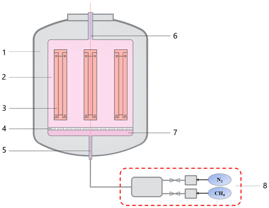
Figure 1.
Schematic diagram of an industrial CVD furnace. (1. Furnace wall; 2. Furnace chamber; 3. Heater; 4. Flow distributor; 5. Gas inlet; 6. Gas outlet; 7. Stable flow chamber; 8. Gas control system).
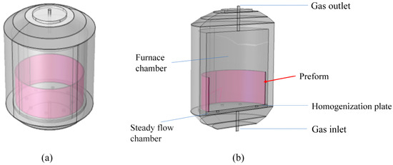
Figure 2.
Structure of the simplified C/C thermal insulation tube deposition furnace. (a) Simplified 3D model; (b) Geometry diagram for simulation.
The CVD process that occurs in the C/C thermal insulation tube high-temperature deposition furnace can be summarized as follows: The process begins by placing the carbon fiber preform on the flow distributor. The furnace is then closed, and a vacuum is applied. Then, the heater is turned on to raise the temperature. Once the furnace reaches the process temperature, process gases (methane and nitrogen) are introduced. After the designated process time has elapsed, cooling commences, and the furnace is subsequently exited.
Reasonable mesh division is crucial for constructing a well-simulated model. Local mesh refinement is performed according to different requirements, specifically at the gas inlet and outlet as well as the through-holes on the flow distributor. From the results shown in Figure 3, it is found that the total number of mesh elements in this simulation scheme was set to 361,643, with an average grid quality of 0.657.
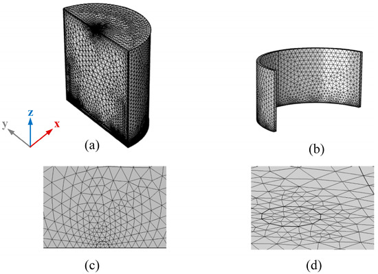
Figure 3.
The diagram of grid division. (a) Center of sedimentation furnace; (b) Thermal insulation tube; (c) Gas inlet; (d) Through hole of uniform flow plat.
In the CVI deposition process, methane (CH4) is utilized as the carbon source gas, while inert nitrogen (N2) is used for dilution and protection. After entering the reaction chamber, the precursor gas methane undergoes cracking at high temperatures. Through a series of complex gas-phase reactions and heterogeneous surface reactions [8,9,10], solid carbon particles are formed on the surface of the thermal insulation tube. To improve computational convergence and reduce computational costs, the chemical reaction kinetics follow a multi-step reaction model proposed by Li [25,26,27], which tracks and measures the deposition results of the carbon particles generated during this process. These products include ethylene (C2H4), acetylene (C2H2), and benzene (C6H6) from homogeneous gas-phase reactions, as well as heterogeneous surface reaction products from the cracking of methane, ethylene, acetylene, and benzene.
3. Multi-Physics Field Coupling Simulation Modeling
Assuming the reactant gases are incompressible ideal gases, this assumption is highly consistent with the actual situation at low pressure. Based on the requirements for circular structure and uniformity, it is assumed that the carbon/carbon insulation cylinder preform is isotropic. It is also assumed that the high-temperature gas pyrolysis reaction is an irreversible first-order reaction, and the gas inlet region exhibits fully developed laminar flow.
where denotes the fluid density. denotes the dynamic viscosity of the fluid. and denote the fluid velocity vector and the unit vector, respectively.
Since the subject of this study is the thermal insulation tube preform, which is a typical porous medium, and considering that the momentum of the gas within the porous preform is transferred through shear forces, we establish the Brinkman equation and the continuity equation for the gas flow within the thermal insulation tube are established [28,29]:
where is the porosity of the prefabricated thermal insulation tube, is the permeability of the prefabricated thermal insulation tube, represents the change in fluid mass during the sedimentation process.
Establishing partial differential equations for concentration changes in the free flow zone and thermal insulation tube prefabricated body inside the sedimentation furnace:
where is the concentration of the corresponding component gas, and represent the diffusion coefficients of various gas substances in the free flow area in the center of the sedimentation furnace and in the porous preform, and represent the reaction rate of each component gas in the free flow area in the center of the deposition furnace and within the porous preform, as shown in Table 1.

Table 1.
Chemical reaction rates in free flow regions and porous media regions [30].
The process of porosity and density changes in prefabricated bodies can be represented by the following equation:
where is the deposition rate of pyrolytic carbon, is the area-to-volume ratio of pores in the preform, is the molar mass of pyrolytic carbon, and is the density of pyrolytic carbon.
Among them, adopts a multi-deformation pore carbon fiber model [14]:
In Equation (10), is the radius of the carbon fiber. is the initial porosity, and is the porosity during the CVI process.
This simulation scheme is based on the geometric model, grid division, CVI reaction, and multi-physics field coupling mentioned above.
To ensure the reliability and accuracy of the simulation scheme and its results, the validation tests were conducted [20]. This validation targeted two types of preforms: carbon fiber felt and carbon cloth laminate. Both preforms were laboratory-prepared, precision-sized small samples, with cylindrical dimensions of 46 mm (outer diameter) × 36 mm (inner diameter) × 58 mm (height). The process parameters were taken from the reference [31], with methane as the precursor gas, a deposition temperature of 1343 K, a pressure of 30 kPa, and a densification time of 120 h. Using the average density of the preform at different times as a parameter, it is found that the simulation results were consistent with the experimental data [31] in terms of the trend. The average errors between the experimental and corresponding simulation values for the densification of the two preforms were 0.0203 g/cm3 and 0.0284 g/cm3, with root mean square errors of 4.94% and 3.71%, respectively [8,9,10]. Based on these validation results, the simulation scheme established in this study was considered to be feasible and effective.
4. Results and Discussion
Assuming the initial parameters of the thermal insulation tube preform are as follows: outer diameter of 1185 mm, inner diameter of 1130 mm, height of 560 mm, initial density of 0.45 × 10³ kg/m3, and initial porosity of 0.69.
This work aims to optimize the fabrication process and product characteristics of a 36-inch C/C thermal insulation tube. First, a large amount of actual process data was summarized and organized. A simulation experiment was conducted using a set of actual process parameters for a 36-inch thermal insulation tube as fixed process conditions. In this scheme, the deposition temperature is set to 1180 K, the flow rate of the precursor gas methane is 85 L/min, the inlet supply pressure is 0.1 MPa, and the densification time is 100 h, respectively. However, the simulation results show that under these process conditions, after 100 h of densification, the average density of the thermal insulation tube is 1.22 × 10³ kg/m3, with a densification rate of 2.04 × 10⁻³ kg/m3/s. The density uniformity along the Z-axis direction inside the thermal insulation tube is relatively poor, and the results are not ideal.
Next, the process conditions were changed, and numerous simulation experiments and analyses were conducted. The layout of the heating elements in the deposition furnace and the relative position of the thermal insulation tube within the furnace significantly influence the spatial transport of chemical reactants. Adjusting the axial position of the thermal insulation tube preform in the center of the thermal field can effectively change the transport of chemical reactants within the preform. The most convenient method is to place graphite pads of appropriate thickness at the bottom of the deposition furnace, as placing graphite pads of varying thicknesses under the thermal insulation tube preform effectively alters the distribution state of the reactant gases in different regions of the preform, potentially improving the axial density uniformity of the insulation tube. Based on the aforementioned layout and process optimization strategy, systematic simulation experiments were conducted. It is found that the selection of the graphite pad height has a significant impact on the densification effect of the thermal insulation tube.
By setting the graphite pad thickness to 20 mm, 40 mm, 60 mm, 80 mm, and 100 mm, respectively, five different CVI process gas distribution states were obtained. Figure 4 shows the density distribution cloud diagram of the thermal insulation tube after 100 h of densification for different graphite pad thicknesses. It can be observed that compared to the case with no graphite pad (0 mm), the surface density on both the inner and outer sides of the thermal insulation tube increases with the thickness of the graphite pad, and the high-density region is more concentrated at the bottom of the thermal insulation tube. Figure 5 shows the average density and densification rate curves of the thermal insulation tube for different graphite pad thicknesses. As the thickness of the graphite pad increases, both the average density and the densification rate increase as well. After 100 h of densification, the average density ranges from 1.22 × 10³ kg/m3 to 1.28 × 10³ kg/m3, and the densification rate ranges from 2.04 × 10⁻³ kg/m3/s to 2.55 × 10⁻³ kg/m3/s, with fluctuations in these data becoming significantly smaller. These changes are mainly due to the placement of the graphite pad, which shifts the relative position of the uniform flow region of the chemical reactant components, thus increasing the uniform concentration distribution area of the intermediate products acetylene and benzene on both the inner and outer sides of the insulation tube preform. Consequently, the uniform range of carbon particles generated by pyrolysis penetrating deeper into the preform expands, effectively improving the average density and densification rate.
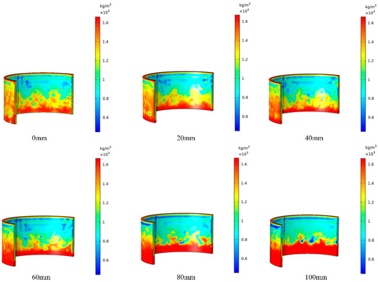
Figure 4.
Density distribution cloud map of the thermal insulation tube with different graphite pad heights after 100 h of densification.
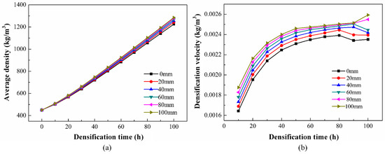
Figure 5.
Some simulation results-the influence of graphite pad height on densification (a) Average density; (b) Densification rate.
In order to effectively predict the densification behavior inside the thermal insulation tube, the simulation object is selected as the centerline of the symmetrical plane along the Z-axis of the insulation tube, as shown in Figure 6a. Figure 6b shows the density variation along this axis. It can be found that after placing the graphite pad, the axial density of the thermal insulation tube has improved to some extent. Compared to the case without a graphite pad (0 mm), the maximum density at the lower position of the thermal insulation tube (z = 0–0.058 m) significantly increases when the graphite pad thicknesses are 20 mm and 40 mm, but with considerable fluctuations. With a further increase in graphite pad thickness, the density fluctuations noticeably decrease, and the uniformity is improved. Examining the axial density variation curves for graphite pad thicknesses of 60 mm, 80 mm, and 100 mm, it is evident that adjusting the graphite pad thickness has a minor effect on the maximum density at the investigation site, with all values not less than 1.60 × 10³ kg/m3 and showing smaller variations. The minimum density increased with the graphite pad thickness, indicating an effective improvement in the axial uniformity and deposition density of the thermal insulation tube.
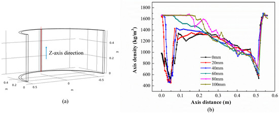
Figure 6.
The influence of graphite pad height on axial density. (a) Schematic diagram of the centerline in the Z-axis direction; (b) Density variation on the centerline in the Z-axis direction.
Furthermore, when the graphite pad thickness is 80 mm, the minimum density at the inspection site is 0.738 × 10³ kg/m3; however, with a graphite pad thickness of 100 mm, the minimum density starts to show a decreasing trend, indicating that the graphite pad thickness should not be increased further. Clearly, under our experimental conditions, there exists an optimal graphite pad thickness. This is mainly because the presence of the graphite pad effectively changes the relative position of the thermal insulation tube preform within the deposition furnace, allowing for an effective match between the uniform reaction zone and the preform. When the positions are poorly matched, meaning the graphite pad is too high or too low, the high-concentration reactant accumulation zone can cause some carbon particles to rapidly deposit on the surface of the thermal insulation tube. This premature closure of the surface pores results in fewer carbon particles penetrating into the interior, leading to poorer density uniformity and lower deposition rates for the thermal insulation tube.
Figure 7 shows the comparison of average density for the cases without a graphite pad (0 mm) and with an 80 mm graphite pad. It is evident that with an 80 mm thick graphite pad, the average density at the inspection site inside the thermal insulation tube increases to 1.436 kg/m3, which is a 47% improvement compared to the 0.975 kg/m3 result without the graphite pad. The minimum density increases from 0.523 × 10³ kg/m3 to 0.738 × 10³ kg/m3, representing a 41% improvement. Thus, using a graphite pad of appropriate thickness can effectively enhance the densification of low-density regions. Moreover, our experimental and analytical results indicate that, within the existing system, the atmospheric distribution varies with height, for which an optimal position has been identified.
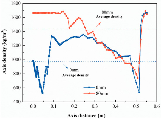
Figure 7.
The density comparison at the inspection site for the graphite pad with a height of 80 mm.
Based on the optimization strategy of introducing a graphite pad independently proposed in this paper, comprehensive computer simulation experiments were systematically conducted, and the massive resulting data were thoroughly analyzed and discussed. It is found that introducing a graphite pad can conveniently and effectively alter the deposition conditions of carbon particles in low-density regions, significantly improving the uniformity and densification of the thermal insulation tube. Under the experimental conditions of this study, the densification effect is optimal when the graphite pad height is 80 mm. In practical production, referring to this scheme, the new process of introducing an appropriate graphite pad, coupled with reasonable adjustment of the deposition furnace layout and process parameters, effectively enhances the densification and deposition density uniformity of the C/C thermal insulation tube. This also improves the deposition rate and shortens the process cycle. Additionally, this conclusion has important implications for optimizing different-sized CVI processes and enhancing the performance of C/C composite materials.
5. Conclusions
This paper proposes a precise geometric model, a method of appropriate grid division as well as a simulation scheme of multi-field coupling. On this basis, first, an optimization strategy involving the introduction of a graphite pad is proposed to enable effective adjustment of reactant distribution in various regions of the thermal insulation tube preform. Then, a three-dimensional multi-field coupled simulation model is established, which can effectively simulate the large-sized C/C thermal insulation tube. Based on the simulation results, it is found that the choice of graphite pad thickness has a significant impact on the densification effect of the thermal insulation tube. Therefore, introducing a graphite pad is a key measure to enhance the densification and uniformity of the thermal insulation tube. Specifically, when the graphite pad thickness is 80 mm, the optimal performance of the C/C thermal insulation tube is observed, achieving a 47% increase in average density and significantly improved axial uniformity. For the industrial production of 36-inch PV monocrystalline silicon rods, this optimization is anticipated to shorten the CVI densification cycle, reduce manufacturing costs, and enhance the thermal field stability during the Czochralski silicon growth process, ultimately contributing to the cost-effective fabrication of higher-quality monocrystalline silicon ingots. This work offers valuable insights for the design of industrial class C/C deposition furnaces and provides a practical reference for improving the performance of the CVI thermal isolation C/C tubes.
Author Contributions
Conceptualization, H.L. and J.Z. (Jicheng Zhou); Methodology, H.L. and J.Z. (Jicheng Zhou); Validation, J.Z. (Jicheng Zhou); Formal analysis, J.Z. (Jianyong Zhan); Investigation, M.L. and H.L.; Writing—original draft, M.L.; Writing—review & editing, J.Z. (Jicheng Zhou); Visualization, J.Z. (Jianyong Zhan); Supervision, J.Z. (Jicheng Zhou); Funding acquisition, J.Z. (Jicheng Zhou). All authors have read and agreed to the published version of the manuscript.
Funding
This research was funded by Dongguan Science and Technology of Social Development Program (Grant no. 20231800940252) and Natural Science Project of Guangdong University of Science and Technology (Grant no. GKY-2024KYZDK-4).
Institutional Review Board Statement
Not applicable.
Informed Consent Statement
Not applicable.
Data Availability Statement
The data that support the findings of this study are available from the Corresponding Author upon reasonable request.
Conflicts of Interest
The authors declare no conflicts of interest to report regarding the present study.
References
- Sharma, M.K.; Bhattacharya, J. Dependence of spectral factor on angle of incidence for monocrystalline silicon based photovoltaic solar panel. Renew. Energy 2022, 184, 820–829. [Google Scholar] [CrossRef]
- Costa, E.C.; Weingaertner, W.L.; Xavier, F.A. Influence of single diamond wire sawing of photovoltaic monocrystalline silicon on the feed force, surface roughness and micro-crack depth. Mater. Sci. Semicond. Process. 2022, 143, 106525. [Google Scholar] [CrossRef]
- Jortner, J.; Priya, N.S. 5.16 Applications of Carbon/Carbon Composites. Compr. Compos. Mater. II 2018, 5, 421–436. [Google Scholar]
- Dong, Z.; Sun, B.; Zhu, H.; Yuan, G.; Li, B.; Guo, J.; Li, X.; Zhang, J. A review of aligned carbon nanotube arrays and carbon/carbon composites: Fabrication, thermal conduction properties and applications in thermal management. New Carbon Mater. 2021, 36, 873–892. [Google Scholar] [CrossRef]
- Tang, B.; Wang, Y.; Hu, L.; Lin, L.; Ma, C.; Zhang, C.; Lu, Y.; Sun, K.; Wu, X. Preparation and properties of lightweight carbon/carbon fiber composite thermal field insulation materials for high-temperature furnace. J. Eng. Fibers Fabr. 2019, 14, 1558925019884691. [Google Scholar] [CrossRef]
- Li, J.; Guo, P.; Hu, C.; Pang, S.; Ma, J.; Zhao, R.; Tang, S.; Cheng, H. Fabrication of large aerogel-like carbon/carbon composites with excellent load-bearing capacity and thermal-insulating performance at 1800 °C. ACS Nano 2022, 16, 6565–6577. [Google Scholar] [CrossRef]
- Wang, H.; Ji, R.; Qu, F.; Bai, J.; Fu, Q.; Li, H. Three-dimensional pore-scale study of the directional heat transfer in a high thermal conductivity carbon/carbon composite protection system. Aerosp. Sci. Technol. 2021, 112, 106609. [Google Scholar] [CrossRef]
- Zhou, J.; Lv, B.; Liang, H.; Wen, Z. Simulation and optimization of polysilicon thin film deposition in a 3000 mm tubular LPCVD reactor. Sol. Energy 2023, 253, 462–471. [Google Scholar] [CrossRef]
- Zhou, J.; Huang, J.; Liao, J.; Guo, Y.; Zhao, Z.; Liang, H. Multi-field simulation and optimization of SiNx: H thin-film deposition by large-sized tubular LF-PECVD. Sol. Energy 2021, 228, 575–585. [Google Scholar] [CrossRef]
- Zhou, J.; Xu, W.; Chen, T. An investigation on improving the homogeneity of plasma generated by linear microwave plasma source with a length of 1550 mm. Plasma Sci. Technol. 2021, 23, 025401. [Google Scholar] [CrossRef]
- Huang, X.; Zhang, H. Hot-Zone Design of Carbon/Carbon-Metal Sandwich Structure Composite Using CVI/CVD Material Processing. In Proceedings of the ASME 2023 Heat Transfer Summer Conference collocated with the ASME 2023 17th International Conference on Energy Sustainability, Washington, DC, USA, 10–12 July 2023; Volume 87165, p. V001T09A002. [Google Scholar]
- Shang, T.; Ge, J.; Yang, J.; Li, M.; Liang, J. Spatiotemporal prediction of surface roughness evolution of C/C composites based on recurrent neural network. Compos. Part A-Appl. Sci. 2024, 186, 108429. [Google Scholar] [CrossRef]
- Zenzen, R.; Khatir, S.; Belaidi, I.; Le Thanh, C.; Wahab, M.A. A modified transmissibility indicator and Artificial Neural Network for damage identification and quantification in laminated composite structures. Compos. Struct. 2020, 248, 112497. [Google Scholar] [CrossRef]
- Kim, H.G.; Ji, W.; Kwon, H.J.; Yoon, S.; Kim, J.I.; Bae, S.; Cho, N.C. Full-scale multi-physics numerical analysis of an isothermal chemical vapor infiltration process for manufacturing C/C composites. Carbon 2021, 172, 174–188. [Google Scholar]
- Liu, Z.; Jiang, X.; Li, Z.; Zheng, Y.; Nie, J.J.; Cui, Z.; Liang, Y.; Zhu, S.; Chen, D.; Wu, S. Recent progress of photo-excited antibacterial materials via chemical vapor deposition. Chem. Eng. J. 2022, 437, 135401. [Google Scholar] [CrossRef]
- Pandey, A.; Selvam, P.; Dhindaw, B.K.; Pati, S. Multiscale modeling of chemical vapor infiltration process for manufacturing of carbon-carbon composite. Mater. Today 2020, 21, 1059–1063. [Google Scholar]
- Niu, C.; Zhang, Q.; Cheng, L.; Ye, F.; Zhang, L. Microstructure and mechanical properties of Cf/SiC composites with dispersed C-SiC interphase prepared by chemical vapor infiltration. Compos Part. A-Appl. Sci. Manuf. 2023, 165, 107339–107345. [Google Scholar] [CrossRef]
- Sun, G.; Zhang, C.; Zhang, Q.; Zhang, Y.; Cheng, L.; Luan, X.; Yang, C. Microstructure and mechanical properties of SiCf/SiC composite prepared by chemical vapor infiltration. Ceram. Int. 2022, 48, 36983–36991. [Google Scholar]
- Lv, X.; Ye, F.; Cheng, L.; Fan, S.; Liu, Y. Fabrication of SiC whisker-reinforced SiC ceramic matrix composites based on 3D printing and chemical vapor infiltration technology. Eur. Ceram. Soc. 2019, 39, 3380–3386. [Google Scholar]
- Zhou, J.; Zhan, J.; Liang, H.; Guo, Y.; Zhao, B.; Hao, L.; Zhang, T.; Jiang, B. Modeling for the Fabrication Process of a ϕ1185 mm C/C Composite Thermal Insulation Tube in an Isothermal Chemical Vapor Infiltration Reactor. Coatings 2024, 14, 756. [Google Scholar] [CrossRef]
- Du, W.; Zeng, F.; Huang, R.; Chen, M.; Li, Z.; Li, Z. Numerical simulation and experimental validation of ICVI-C/C reaction process by methane/propane gas mixture source. J. Ind. Eng. Chem. 2025, 143, 184–196. [Google Scholar] [CrossRef]
- Akhare, D.; Chen, Z.; Gulotty, R.; Luo, T.; Wang, J. Probabilistic physics-integrated neural differentiable modeling for isothermal chemical vapor infiltration process. npj Comput. Mater. 2024, 10, 120. [Google Scholar] [CrossRef]
- Kumar, D.; Painuly, A.; Viswanath, V.G.K.; Agarwal, D.K.A.; Nageswaran, G. Impact of process parameter on the behavior of pyrocarbon deposition in chemical vapour infiltration (CVI) process. Carbon Trends 2024, 16, 100380. [Google Scholar] [CrossRef]
- Du, D.; Liang, X.; Li, W.; Wang, Y.; Zhang, Z. A novel integrated forming strategy based on chemical vapor infiltration for C/C honeycomb with variable stiffness. J. Sandw. Struct. Mater. 2024, 26, 1265–1287. [Google Scholar] [CrossRef]
- Delhaes, P. Chemical vapor deposition and infiltration processes of carbon materials. Carbon 2002, 40, 641–657. [Google Scholar] [CrossRef]
- Li, H.; Li, A.; Bai, R.; Li, K. Numerical simulation of chemical vapor infiltration of propylene into C/C composites with reduced multi-step kinetic models. Carbon 2005, 43, 2937–2950. [Google Scholar] [CrossRef]
- Li, A.; Deutschmann, O. Transient modeling of chemical vapor infiltration of methane using multi-step reaction and deposition models. CES 2007, 62, 4976–4982. [Google Scholar]
- Li, A.; Norinaga, K.; Zhang, W.; Deutschmann, O. Modeling and simulation of materials synthesis: Chemical vapor deposition and infiltration of pyrolytic carbon. Compos. Sci. Technol. 2008, 68, 1097–1104. [Google Scholar] [CrossRef]
- Masoodi, R.; Pillai, K.M. Darcy’s law-based model for wicking in paper-like swelling porous media. AIChE J. 2010, 56, 2257–2267. [Google Scholar] [CrossRef]
- COMSOL. CFD Module User’s Guide, COMSOL Multiphysics®; v. 5.6.; COMSOL: Göttingen, Germany, 2020; pp. 591–605. [Google Scholar]
- Vignoles, G.L.; Goyhénèche, J.M.; Sébastian, P.; Puiggali, J.R.; Lines, J.F.; Lachaud, J. The film-boiling densification process for C/C composite fabrication: From local scale to overall optimization. CES 2006, 61, 5636–5653. [Google Scholar] [CrossRef]
Disclaimer/Publisher’s Note: The statements, opinions and data contained in all publications are solely those of the individual author(s) and contributor(s) and not of MDPI and/or the editor(s). MDPI and/or the editor(s) disclaim responsibility for any injury to people or property resulting from any ideas, methods, instructions or products referred to in the content. |
© 2025 by the authors. Licensee MDPI, Basel, Switzerland. This article is an open access article distributed under the terms and conditions of the Creative Commons Attribution (CC BY) license (https://creativecommons.org/licenses/by/4.0/).