Article

Microstructure and Wear Resistance of Plasma-Sprayed Al2O3-TiO2-CeO2/YSZ Composite Coatings

College of Naval Architecture and Port Engineering, Shandong Jiaotong University, Weihai 264310, China
*
Author to whom correspondence should be addressed.
Coatings 2025, 15(10), 1164; https://doi.org/10.3390/coatings15101164 (registering DOI)
Submission received: 5 September 2025 / Revised: 25 September 2025 / Accepted: 27 September 2025 / Published: 5 October 2025
(This article belongs to the Section Corrosion, Wear and Erosion)

Abstract

Yttria-stabilized zirconia(YSZ) was introduced into the Al2O3-TiO2-CeO2 coating prepared by plasma spraying to improve the wear resistance of the coating and prolong the service life of the weathering steel. The nano-agglomerated powder was prepared by mechanical ball milling and spray-drying technology, powder was sprayed on the surface of Q355 steel substrate by atmospheric plasma sparing (APS), the Al2O3-TiO2-CeO2/YSZ composite coating was prepared, and the effects of YSZ on the phase, microstructure, and tribological properties of the composite coating were studied. The results show that nano-agglomerated powders with micron size (average size 55 μm) can be prepared by spray-drying technology, and after high-temperature sintering, the nano-agglomerated powders are denser and form the α-Al2O3 phase. The composite coating prepared by plasma spraying has a bimodal structure, and after adding YSZ, the phases in the coating are mainly α-Al2O3, γ-Al2O3, and t-ZrO2, the grain size is fine, and the porosity is reduced. The specific wear rate is only 4.4 × 10⁻⁵ mm3 N−1·m−1, the relative wear resistance is 6.3 times higher than that of the substrate, and the wear mechanism of the coating is mainly slight adhesive wear and abrasive wear, which shows excellent friction and wear properties at room temperature.

1. Introduction

For the purpose of improving of Q355 steel under friction conditions, thermal-spraying technology based on metal [1,2], ceramic [3,4], cermet [5,6], and amorphous metal [7,8] coatings has become the main way to solve this problem. Among them, plasma-spraying technology (APS) has become a prevalent method in the preparation of metal and ceramic coatings, owing to its ability to adapt to diverse materials, its controllable process characteristics, and its high level of efficiency [9,10]. Wang et al. [11] used APS to prepare Al2O3-xTiO2 coatings, and compared with the substrate, the hardness of the coating with TiO2 was improved, and the coating with 13% TiO2 had better wear resistance, but it was easy to cause stress fatigue and wear.
Ceramic coatings have become a research focus due to their elevated hardness and exceptional properties [12,13,14]. Masanta [15], Li [16], and Carnier [17] combined a variety of components to give full play to the advantages of each component and improve mechanical properties such as wear resistance. In the Al2O3-TiO2-CeO2 system spray coating, TiO2 with a low melting point can fill the pores of Al2O3 during the spraying process, Al2O3 can inhibit the plastic deformation of TiO2, and CeO2 with higher chemical activity can refine the grain through the grain boundary pinning effect, improve the compactness of the coating [18,19,20,21]. However, with Al2O3 as the base phase, the system presents the brittle characteristics of typical ceramic materials, and the coating is prone to cracks and even peeling, which limits its application in a frictional environment. Yttria-stabilized zirconia (YSZ) is extensively used as a reinforcing material in many engineering fields to improve wear resistance due to its unique toughening mechanism and low thermal conductivity [22,23,24]. Mehar [25], Wang [26], and others also demonstrated in their studies that the wear resistance of coatings can be improved by YSZ. These performance advantages are closely related to the structure, where Y3+ in YSZ replaces Zr4+ to introduce oxygen vacancies and stabilize the tetragonal phase at room temperature, while strengthening toughness through spontaneous lattice distortion strain to induce domain metamorphic reorientation [27,28]. Micro-crack toughening, grain boundary strengthening, and fine-grained toughening can inhibit crack propagation and improve the stability and durability of coatings under wear [29,30,31]. Among them, micro-crack toughening is a mechanism to enhance the anti-crack propagation ability through the stress field in the process of crack propagation, so that the crack encounters the resistance of microstructure such as micro-cracks and particles in the propagation process, so as to effectively disperse the energy of the crack and slow down the crack propagation rate. Liu et al. [32] introduced YSZ with different amounts of Y2O3 into a mixture of alumina and BaZrO3 powders, and the crack deflection/bridging and phase transformation toughening of ZrO2 played a role in refining the Al2O3 grains. Meng et al. [33] prepared a toughened, high-quality YSZ coating with a stable structure that disperses thermal stress and inhibits crack propagation within the coating. However, the effect of YSZ on the microstructure and wear properties of Al2O3-TiO2-CeO2 multicomponent ceramic coatings needs to be further explored.
Compared with traditional materials, nanomaterials exhibit excellent mechanical properties, but their small particle size, high chemical activity, strong adhesion, extremely poor fluidity, and easy clogging of feed nozzles mean they are unable to be directly used for APS [34,35]. To solve this problem, nano-powder regranulation technology (mechanical ball milling, spray drying, etc.) can be prepared into plasma-spraying micron powder with good fluidity. Carpio [36], Vicent [37], and Loghman [38] used spray-drying technology to improve the fluidity of the powder, but also reserved the nano properties of the original powder, and the powder could be prepared with a bimodal structure coating with a high thermal cycle life and better thermal shock performance by using APS.
In this paper, micron-sized nano-agglomerated powders were prepared via a combination of mechanical ball milling and spray drying, and subsequently used to fabricate Al2O3–10 wt.% TiO2–2 wt.% CeO2 multicomponent ceramic composite coatings with 0 wt.% and 6 wt.% YSZ via plasma spraying. The effects of YSZ on the phase composition, microstructure, and room-temperature friction and wear behaviors of the coatings were systematically investigated. Furthermore, the evolution of the worn surfaces during friction was analyzed to elucidate the toughening mechanism imparted by YSZ, highlighting its role in impeding crack propagation during wear. These findings provide theoretical guidance for the design and optimization of high-performance multicomponent ceramic coatings.

2. Experimental Procedures

2.1. Powder Preparation and Coating Preparation

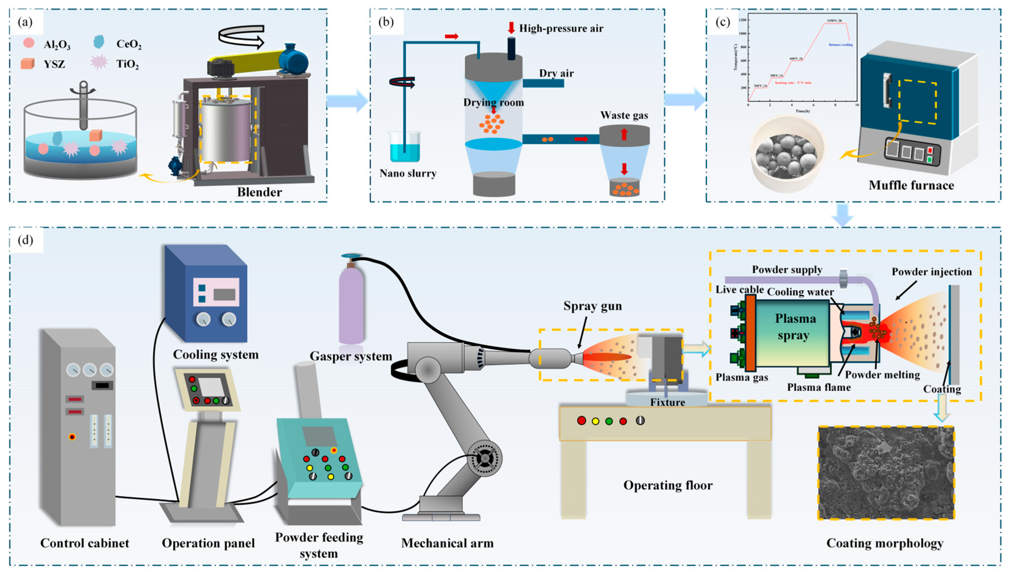
The original materials in this paper were nanoscale powder Al2O3 (purity ≥ 99.5%, particle size: ~20 µm), TiO2 (purity ≥ 99.9%, particle size: ~50 µm), CeO2 (purity ≥ 99.9%, particle size: ~20 µm), 8YSZ (purity ≥ 99.9%, particle size: ~30 µm), and NiCrAlY (purity ≥ 99.9%, particle size: ~80 µm), the Al2O3–10 wt.% TiO2–2 wt.% CeO2 system is denoted as ATC, and the Al2O3–10 wt.% TiO2–2 wt.% CeO2/6 wt.% YSZ system is denoted as ATC-6Y, as shown in Figure 1. Firstly, each powder was mixed in a stirring ball mill (ATX-100, Minghai Powder, Wuxi, China) at a speed of 300 r·min−1, zirconia ball:powder:deionized water was 10:1:3, mixed for 12 h, polyvinyl alcohol (PVA) was added as a binder, the PVA content was controlled at 1% of the total material, and the ball was ground for 24 h to prepare a slurry with uniform powder distribution (Figure 2a). Then, the powder with high spherical size and a uniform particle size distribution was prepared by spray dryer technology (SFL-12, Shanghai Dachuanyuan Drying Equipment Co., Ltd., Shanghai, China), and its working parameters were as follows: inlet air temperature was 220 °C, outlet air temperature was 110 °C, feed rate was 3 L·h−1, and nozzle speed was 180 r·s−1 (Figure 2b). Finally, the nano-agglomerated powder was treated by high-temperature sintering technology, and the sintering process was stepped temperature for heating (Figure 2c), in which the temperature was kept at low temperature points of 200 °C, 350 °C, and 600 °C for 1 h, and at 1150 °C for 2 h, to ensure the full volatilization of PVA and improve the density of the nano-agglomerates [39].
In order to remove the scale and rust on the surface of the substrate, 16-mesh white corundum sand is used to blast the surface of the Q355 steel substrate for surface pretreatment, the blasting angle is 75°, and the pressure is set to 0.7 MPa. Then, the samples were added to ethanol, cleaned for 5 min using an ultrasonic cleaner, dried, and reserved, and the substrate was heated to 100 °C and kept warm for 2 h before spraying. When spraying, in order to reduce the difference in the thermal expansion coefficient between the coating and the substrate, 90 μm NiCrAlY was sprayed first as the bond coating, and then 200 μm ATC-6Y composite nano-coating was sprayed; the spraying parameters are shown in Table 1, and the preparation process is shown in Figure 2d.

2.2. Microstructure Observation and Performance Testing

Double-beam scanning electron microscopy (TES CAN AMBER, TESCAN, Brno, Czech Republic) was used to observe the microstructure of powders and coating. The phases of the powder and APS coating were detected using an X-ray diffractometer (DX-2700BH, Dandong Haoyuan Instrument Co., Ltd., Dandong, China) 30 kV with a ray source of Cu and a wavelength of 0.154 nm in the range of 20–90° and a scanning speed set to 6°/min. Ion-thinning technology was used to prepare the specimens by thinning the specimen blocks to 3 mm in diameter and 30 μm in thickness at a distance of 20–30 μm from the upper surface of the coating, and high-resolution electron microscopy images were obtained by transmission electron microscopy (JEM-F200, Japan Electronics Co., Ltd., Osaka, Japan) to analyze the microstructure of the coating. In accordance with the GB/T 8642 standard [40] for determining the bonding strength of thermal-spraying coatings, the coating bonding strength test was carried out by using an electronic universal material testing machine (Instron-5569, INSTRON, Norwood, MA, USA), and the test was carried out by the dual specimen tensile method; the tensile rate was 2 mm/min, three samples of each were taken during stretching, the average value was taken, and the calculation formula was as follows (1). In accordance with the stipulated requirements of the GB/T 8642 standard, the coating bonding strength test was conducted utilizing an electronic universal material testing machine (Instron-5569, INSTRON, USA). The test method employed was the dual specimen tensile method, wherein the tensile rate was set at 2 mm/min, there were three samples for each specimen during the stretching process, and the mean value was calculated. The calculation formula employed is as follows (1):
R = F / S
where R is the coating bonding strength (MPa); S is the cross-sectional area of the fracture surface (mm2); and F is the maximum load (N).
The coating toughness was further evaluated using a nano-indentation tester (KLA G200X, KLA, Chandler, AZ, USA) with an indenter head of Glass’s indenter, with a maximum load of 10 GPa, and each test was conducted at least five times. The friction and wear test of the specimen was carried out by using the MMS-2A pin-disc friction and wear testing machine (Chenda, Jinan, China) with a speed of 200 r·min−1, a load force of 200 N, a time of 600 s, and a friction pair of 45 steel with a hardness of 45 HRC, and three abrasion tests were performed for each coating. The wear marks were measured using the RTEC UP dual-model 3D profiler (Rtec, Yankton, SD, USA), and the specific wear rate was calculated using (2).
W R = 2 π r S / F L
where WR is the specific wear rate (mm3/N∙m); 2πrS is the volume loss (mm3); L is the total sliding distance (m), and F is the load (N). The ZEISS EVO MA10 scanning electron microscope (ZEISS, Oberkchen, Germany) was used to investigate the specimen’s morphology after wear.

3. Results

3.1. Microstructure

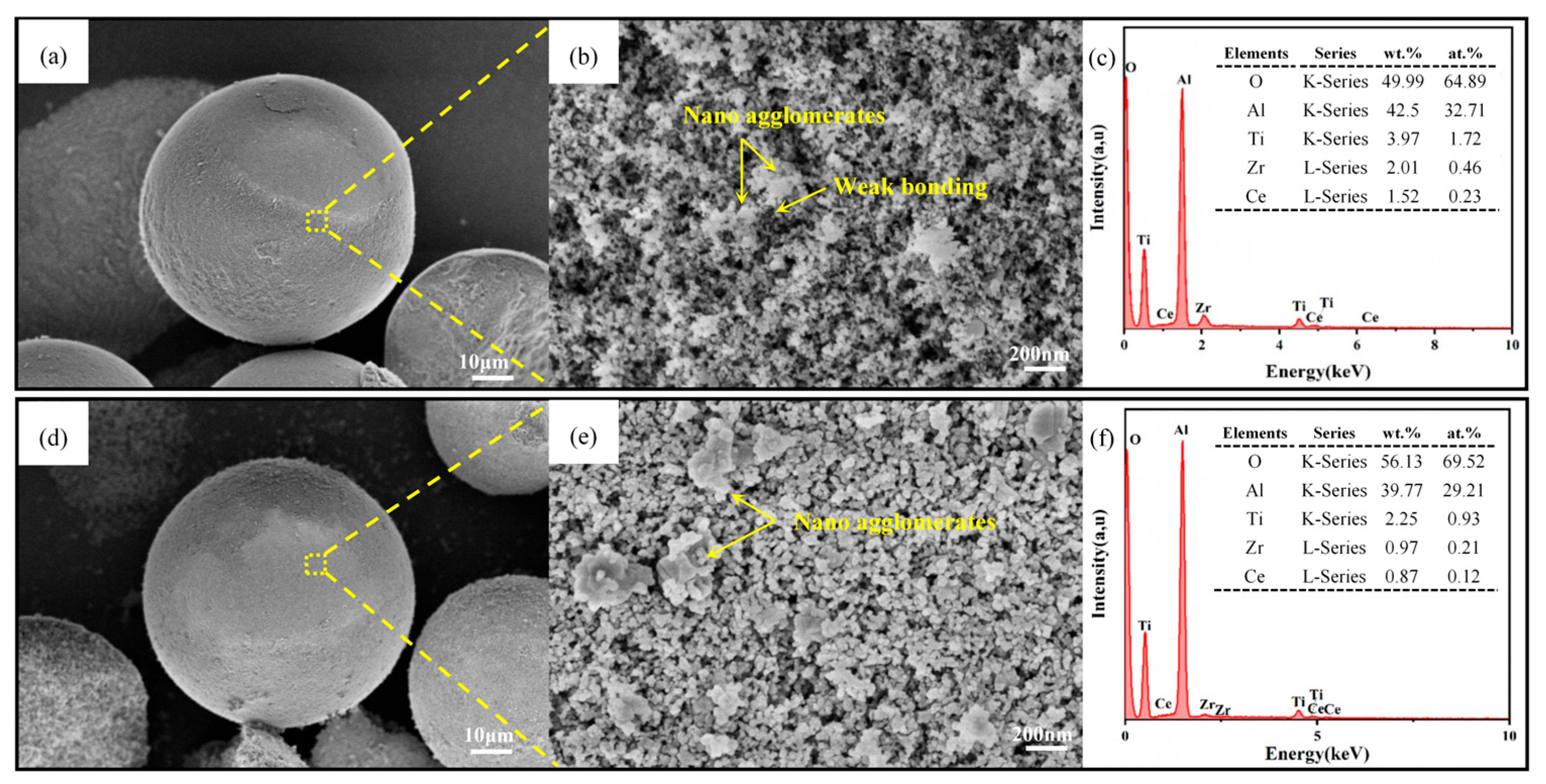
Figure 3 shows the characterization of ATC-6Y powder before and after sintering. From Figure 3a, the agglomerated powder obtained by spray drying is about 55 μm, and there is no remarkable variance in surface morphology. From Figure 3b, the nanostructure is retained in the powder prepared by spray drying, but the powder produces weak adhesion under the action of PVA, its binding force is low, the compactness is poor, it is easy to break under the impact of high-speed plasma gas flow, and it cannot be directly used in plasma spraying. After the nano-agglomerated powder is sintered at high temperature, the particle sphericity is better and the compactness is improved (Figure 3d,e). This phenomenon can be attributed to the volatilization of PVA in the powder at high temperatures, which promotes a better bond between submicron and nanoscale particles. All elements of the nano-agglomerated powder were stable before and after sintering (Figure 3c,f).
Figure 4a shows the XRD diffraction patterns of ATC and ATC-6Y powders before and after sintering, the phases of ATC powder without YSZ are composed of α-TiO2, γ-Al2O3, and CeO2 before sintering, and the phases of powder after sintering are comprised of α-Al2O3, α-TiO2, γ-Al2O3, and CeO2, of which the γ-Al2O3 is converted to α-Al2O3. The phase before the addition of 6 wt.% YSZ powder sintering was composed of α-TiO2, γ-Al2O3, CeO2, and t-ZrO2, and it was found that the α-Al2O3 phase was newly formed after sintering. For the XRD diffraction patterns of ATC and ATC-6Y coatings (Figure 4b), the ATC coatings are primarily constituted of α-Al2O3 and γ-Al2O3, and the ATC-6Y coatings generate new phases t-ZrO2.
During spray drying, nano-agglomerates develop weak adhesions in response to PVA (Figure 4(c1:i,c2:i)). After high-temperature sintering, a better bond was formed between submicron and nanoscale particles, γ-Al2O3 in ATC powder was converted into a new α-Al2O3, and an α-Al2O3 phase was newly formed in ATC-6Y powder (Figure 4(c1:ii,c2:ii)). More γ-Al2O3 and less α-Al2O3 were formed in the coatings (Figure 4(c1:iii,c2:iii)); in order to analyze the cause of this phenomenon, the liquid–solid interface energies of γ-Al2O3 and α-Al2O3 were calculated according to the following equation [41], and the interface energy of γ-Al2O3 was 240 erg cm−2, while that of α-Al2O3 was 390 erg cm−2.
γ = Z i Z a Δ H m / Z i N 1 / 3 v m 2 / 3 + 2 Δ V γ L / 3 V g
where Zi is the number of next-neighbors surrounding an atom in the interior, Za is the number of neighbors of an atom at the surface, ΔHm is the heat of fusion per mole, vm is the molar volume, ΔV/Vg is the fractional volume change, and γL is the liquid surface tension.
First of all, the high cooling rate in the APS process enables the interface to preferentially nucleate the growth of γ-Al2O3 compared with α-Al2O3 [42,43]. Secondly, α-Al2O3 is heated to its molten state rapidly, and during the solidification process, it is easy to form an amorphous state due to its low critical cooling rate, and part of the α-Al2O3 phase changes to metastable-phase γ-Al2O3, while part of Al2O3 does not have time to completely melt, so the α-Al2O3 phase is retained. Compared with the ATC coating, there is an elevated intensity of γ-Al2O3 diffraction peaks and increased γ-Al2O3 content of ATC-6Y coating. To further analyze the cause, the ATC-6Y coating was analyzed using backscattered electron imaging, and as shown in Figure 5a, it can be seen that the content of Y3+ and Zr4+ is higher at the grain boundary (Figure 5b) and lower at the crystal plane (Figure 5c). This is due to the fact that Y3+ can diffuse into the ZrO2 lattice, causing it to undergo lattice distortion and increasing the internal energy of the lattice [44]; Zr4+ has a large ionic radius, which is easy to be enriched at Al2O3 grain boundaries, and which reduces grain boundary energy and makes grain boundaries more stable, thereby restraining the growth of Al2O3 grains and the migration of grain boundaries, hindering the diffusion of Al3+ and O2− ions, and making it difficult to transition from the γ-Al2O3 phase to the thermodynamically stable α phase, so the metastable-phase γ-Al2O3 is more retained [32]. Due to the mutual miscibility between γ-Al2O3 and other oxides, the more the content of γ-Al2O3, the more components with low melting points of the nano-agglomerated powder, the better the melting state of the powder, the easier it is for the material to spread when it hits the substrate or deposits the lamellae, and the tighter the inter-lamellar bonding [45]. In addition, due to the introduction of oxygen vacancies under the doping of Y3+, the resulting lattice distortion reduces the crystallization temperature of the tetragonal phase, so that ZrO2 is stable at room temperature in the tetragonal phase instead of transforming into a monoclinic phase (Figure 4(c2:iii)) [28].
Instrumental broadening was corrected by measuring the standard reference sample (Si) under the same experimental conditions, and the Scherrer formula was utilized in the calculation of the coating’s grain size [46], where the formula is as follows:
D hkl = k λ / β cos θ hkl
where Dhkl is the grain size (nm), k is the constant (k = 0.9), λ is the incident wavelength (λ = 0.15406 nm), β is the width at half maximum (rad), and θ is the diffraction angle (°).
The calculation parameters and results of the grain size of each coating are shown in Table 2. In contrast with the ATC coating, the ATC-6Y coating has a larger FWHM value of 0.414 and a smaller grain size of 20.833 nm. This is attributable to the ionic radius r(Al3+) = 0.0535 nm, r(Ti4+) = 0.0605 nm, and r(Zr4+) = 0.072 nm; in contrast, Zr4+ in the coating has a large ionic radius, which hinders its ability to form a solid solution with Al2O3 and TiO2, and ZrO2 is easy to be enriched at the grain boundary of Al2O3 and plays a pinning role, hindering the movement of grain boundaries and inhibiting grain growth, so the addition of YSZ can play a role in refining grains [47].
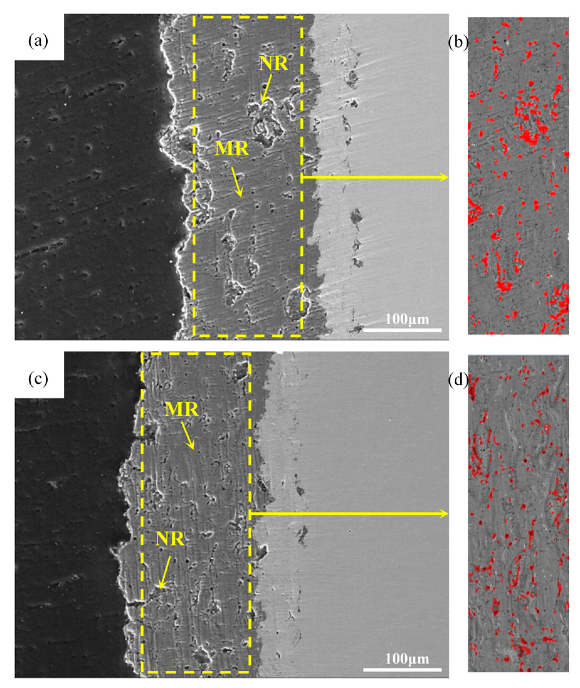
Figure 6 shows the cross-sectional topography of the ATC coating and the ATC-6Y coating. The coating has different microstructures, with the presence of microstructured regions (MRs) in the fully molten and re-solidified regions and nanostructured regions (NRs) in the partially molten and solid sintered regions (Figure 6a,c). The ATC coating has large pores between the lamellar structures, while the ATC-6Y coating has significantly fewer pores (Figure 6b,d). The porosity of the coating was 4.36% for the ATC coating and 2.89% for the ATC-6Y coating according to Image Pro-Plus image-processing software (Image Pro-Plus 6.0), which further indicated that YSZ has the ability to reduce the porosity of the coating and improve its compactness. Because YSZ can improve the wettability of Al2O3, the powder can be fully melted and combined with the capillary action between the nanoparticles to fill the interlayer pores, thereby improving the spreading effect.
Figure 7a,b illustrate the surface morphology of the ATC coating, which was found to have a grooved surface and more defects, including pores and micro-cracks. Firstly, the poor melting effect of the powder affects the spreading effect during deposition, and secondly, the ceramic material and the bond coating have different coefficients of thermal expansion, which can cause thermal stress on the coating, leading to defects. In addition, large spheroid-like particles are distributed on the surface of the coating, and according to Figure 7c, it can be seen that the spheroid-like particles are mainly formed by the rapid solidification of Al2O3 and TiO2 molten droplets and the dominance of surface tension. In comparison with the ATC coating, it was found that the surface cracks of the ATC-6Y coating were reduced (Figure 7d), which was due to the small thermal conductivity and good fracture toughness of ZrO2 in YSZ, which effectively reduced the thermal stress inside the coating caused by thermal mismatch and prevented the generation and extension of these cracks [48]. In addition, the size of the spheroid-like particles was significantly reduced (Figure 7e), and in order to further confirm the constituent elements of the spherical particles, EDS point scans were carried out (Figure 7f), and the spherical particles’ main elements were the same as those of the powder. Combined with Table 2, it can be seen that the addition of YSZ plays a role in refining the grains, making the powder more meltable and spreading at high temperatures. The melting point of YSZ (~2700 °C) is also much higher than that of other components, and its unmelted particles are used as nucleation points to promote the full melting of other components in the nano-agglomerates, thereby reducing the size of spherical particles.
Figure 8 shows the morphology of the MR and NR region in the ATC-6Y coating, and it can be seen that the powder in the MR region has a better molten state and spreads to the surface of the coating, while there are unmelted powder particles in the NR region. In order to further illustrate the distribution of elements in the MR and NR region of the ATC-6Y coating, the area scan is shown in Figure 8b,c, and it is found that the coating’s main elements are Al, Ti, Ce, Zr, Y, and O. In the MR region and NR, Ti and Ce were evenly distributed, indicating that CeO2 and TiO2 were completely melt spreading. As TiO2’s melting point was lower than Al2O3’s, it was more susceptible to heating at high temperature to fill the pores between the Al2O3 particles in the molten state, and it fully underwent solution reaction with Al2O3. CeO2 is easily decomposed into Ce with a low melting point and good wettability under the influence of a high temperature, which can play the role of gap filling and sealing when the material is melted and spread. The Al dispersion distribution arises due to the fact that during the APS process, the temperature in some areas is insufficient to fully melt the Al2O3 particles with high melting points, so that they exist in the form of nano-sized aggregates with other elements. During the coating formation process, Y2O3 can improve the wettability of Al2O3 and reduce the melting point of the nano-agglomerate to make it fully melt, so that Y is evenly distributed in the Al region [26]; Zr is concentrated in the Al region, which is due to the large ionic radius of Zr4+, which is easily enriched at the grain boundary of Al2O3. This indicates that there is ZrO2 with low thermal conductivity and a high melting point in the NR region [49].
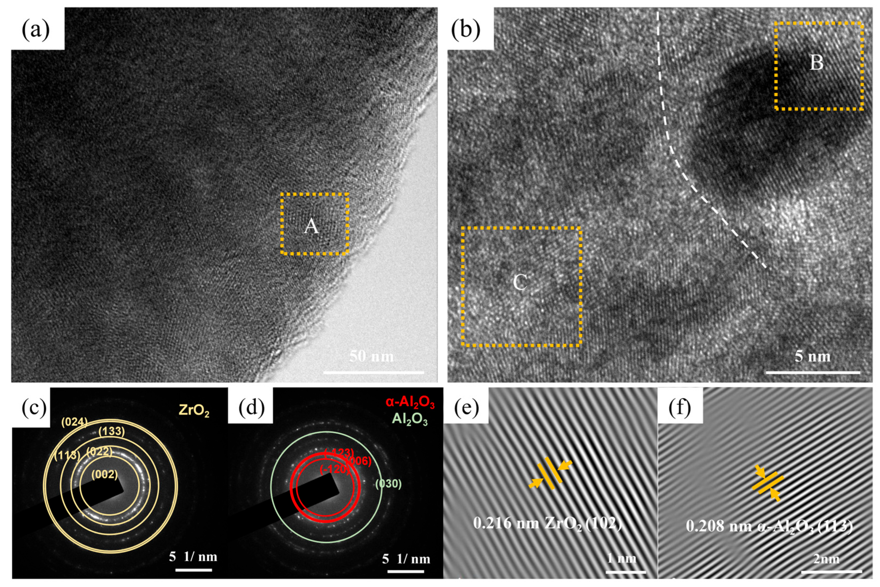
The corresponding HRTEM microscope image of region “A” in Figure 9a can be seen in Figure 9b, where the coating has a clear interface structure, the lattice fringes at the interface are continuous, and there is a good bond between the phases. Figure 9c,d show the selective area electron diffraction (SAED) of Figure 9b, the coating’s phase is dominated by ZrO2 and α-Al2O3 crystal phases, and ZrO2 has the diffraction characteristics of polycrystalline plane orientation (such as (002) and (113) crystal planes), showing a typical polycrystalline structure. Figure 9e shows the high-resolution lattice fringe image of B in Figure 9b, exhibiting a lattice spacing of 0.208 nm for α-Al2O3, corresponding to the (113) plane. Figure 9f illustrates the high-resolution lattice fringes of C in Figure 9b with a lattice spacing of 0.216 mm, corresponding to the (102) plane of tetragonal ZrO2, further illustrating the stable presence of YSZ in the coating [50]. The lattice transition in the interface region is relatively uniform in the high-resolution image, which is due to the fact that YSZ prevents lattice mismatch and dislocation in the interface region by reducing the stress concentration led by the variance in lattice parameters and thermal expansion coefficient between different crystal phases, and it improves the compactness of the coating.

3.2. Mechanical Properties

The bond strength of the coating is key to whether premature failure will occur in the wear state. Figure 10a shows the adhesion strength of the ATC coating and the ATC-6Y coating; the average adhesion strength of the ATC coating without YSZ is 23.3 MPa, and compared with the average adhesion strength of the ATC-6Y coating, which is 25.8 MPa, that marks an increase of 10.7%. Combined with the analysis of transmission results, it can be seen that there is no interfacial cracking phenomenon caused by thermal concentration in the ATC-6Y coating. In addition, the interface transition between different phases of the coating is relatively uniform, indicating that the phases have good lattice bonding, and it also confirms that the ATC-6Y coating with YSZ has good bonding strength.
The H and E data obtained from the nano-indentation curves (Figure 10b) were utilized to calculate the H/E values and H3/E2 values, as illustrated in Table 3. There is a growing recognition that hardness is not necessarily a major demand for wear, and that the tenacity and elasticity of the coating are equally significant factors. The H/E ratio is the elastic strain to failure, and a high H/E ratio is generally regarded as a reliable index of good wear resistance in coatings [51]; H3/E2 is the resistance to plastic deformation, and the higher its value, the better the toughness [52]. In Table 3, the ATC coating has a low H3/E2 value, which is prone to fatigue peeling. In contrast, the H/E and H3/E2 values of the ATC-6Y coating were higher, indicating that the coating with YSZ had greater toughness and enhanced the crack initiation and propagation resistance of the coating.

3.3. Wear Behavior

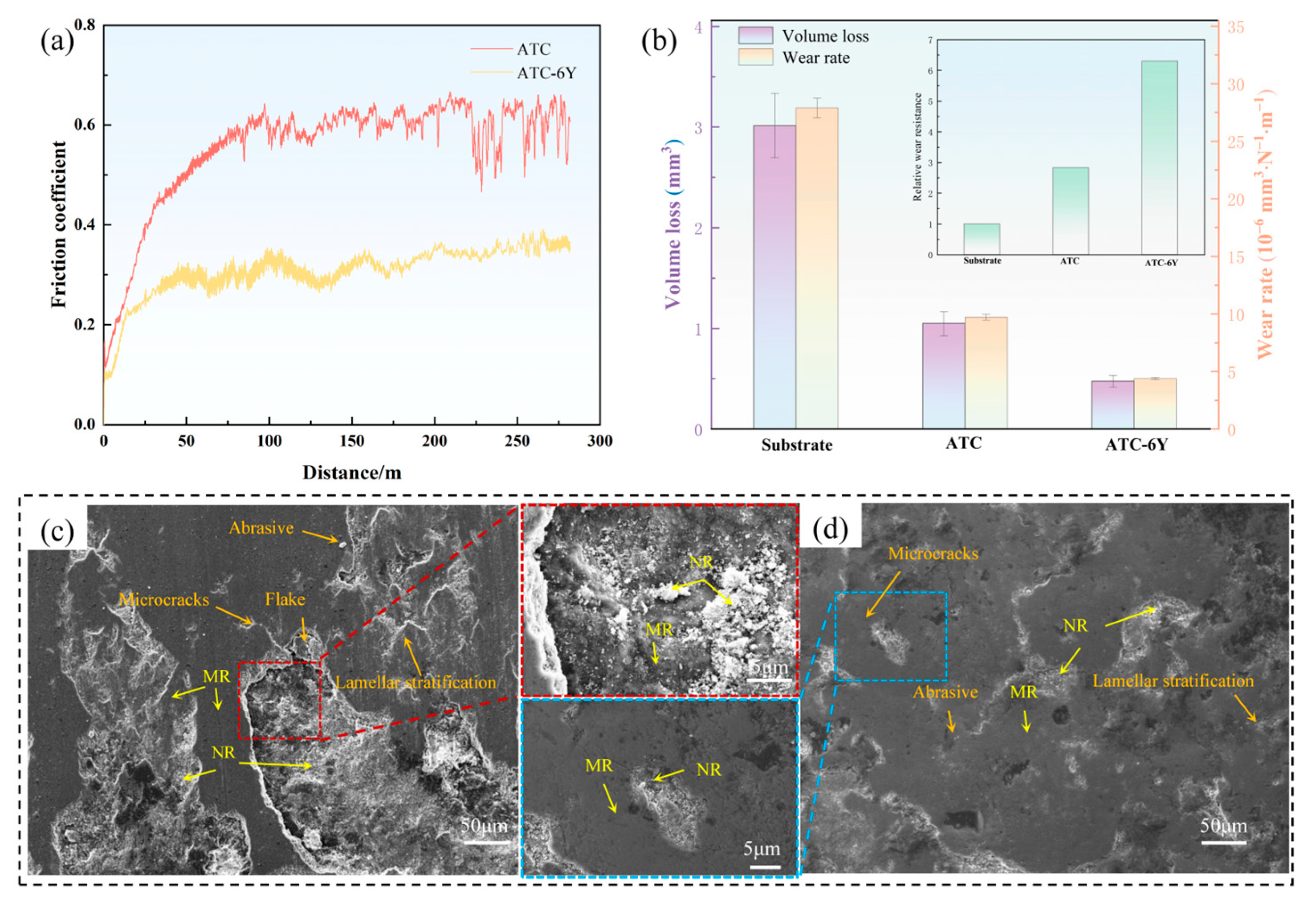
Figure 11a shows the relationship between the factor of friction and displacement of the ATC and ATC-6Y coatings. The factor of friction fluctuates significantly at the original stage of wear of the coating, which is mainly due to the contact instability caused by the surface roughness of the coating and the grinding ring. With the progress of wear, the surface of the coating gradually becomes smoother, the fluctuation of the friction coefficient tends to be relatively stable, and the average friction coefficient (0.34) of the ATC-6Y coating is smaller than that of the ATC coating (0.62). Figure 11b shows the volume loss, specific wear rate, and relative wear resistance of the coating, where the volume loss of the ATC coating is 1.05 mm3, the specific wear rate is 9.72 × 10⁻⁵ mm3·N−1·m−1, and the relative wear resistance is 2.83 times higher than that of the substrate. The volume loss and specific wear rate of ATC-6Y coating were reduced, with a volume loss of 0.475 mm3 and a specific wear rate of 4.4 × 10⁻⁵ mm3·N−1·m−1, while the relative wear resistance was 6.3 times higher than that of the substrate. This is due to the addition of YSZ, which refines the grains, improves the compactness of the coating, and reduces the stress concentration during the friction process, thereby effectively reducing wear losses [53].
Figure 11c,d show the surface wear topography of the ATC coating and the ATC-6Y coating. As can be seen from Figure 11c, there is some flake delamination and there are slight spalling pits on the surface of the ATC coating, and the micro-convex body on the coating surface first contacts with the friction pair during the grinding process, resulting in huge shear stress and plastic deformation of the composite coating surface, and brittle cracking caused by fatigue. Under the synergistic effect of shear stress and load pressure, the surface of the coating is prone to forming pores and micro-cracks, and these defects will spread inward along the weakly connected lamellae, and eventually the coating will peel off and form spalling pits. In Figure 11d, the wear surface of the coating is relatively flat, producing fine abrasive chips, the degree of micro-cracks is significantly reduced, and small tensile cracks are produced near the NR region, while no obvious spalling is found, and the minor adhesive wear and abrasive wear are the main wear mechanisms of the coating. From the boxed high-power images in Figure 11c,d, the presence of unmelted nanoparticles can be observed. These unmelted nanoparticles provide a uniform surface for wear and also contribute to an even load distribution as they slide in uneven places. In addition, the presence of NR also has a hindrance effect on crack propagation, which is conducive to reducing the degree of wear damage.
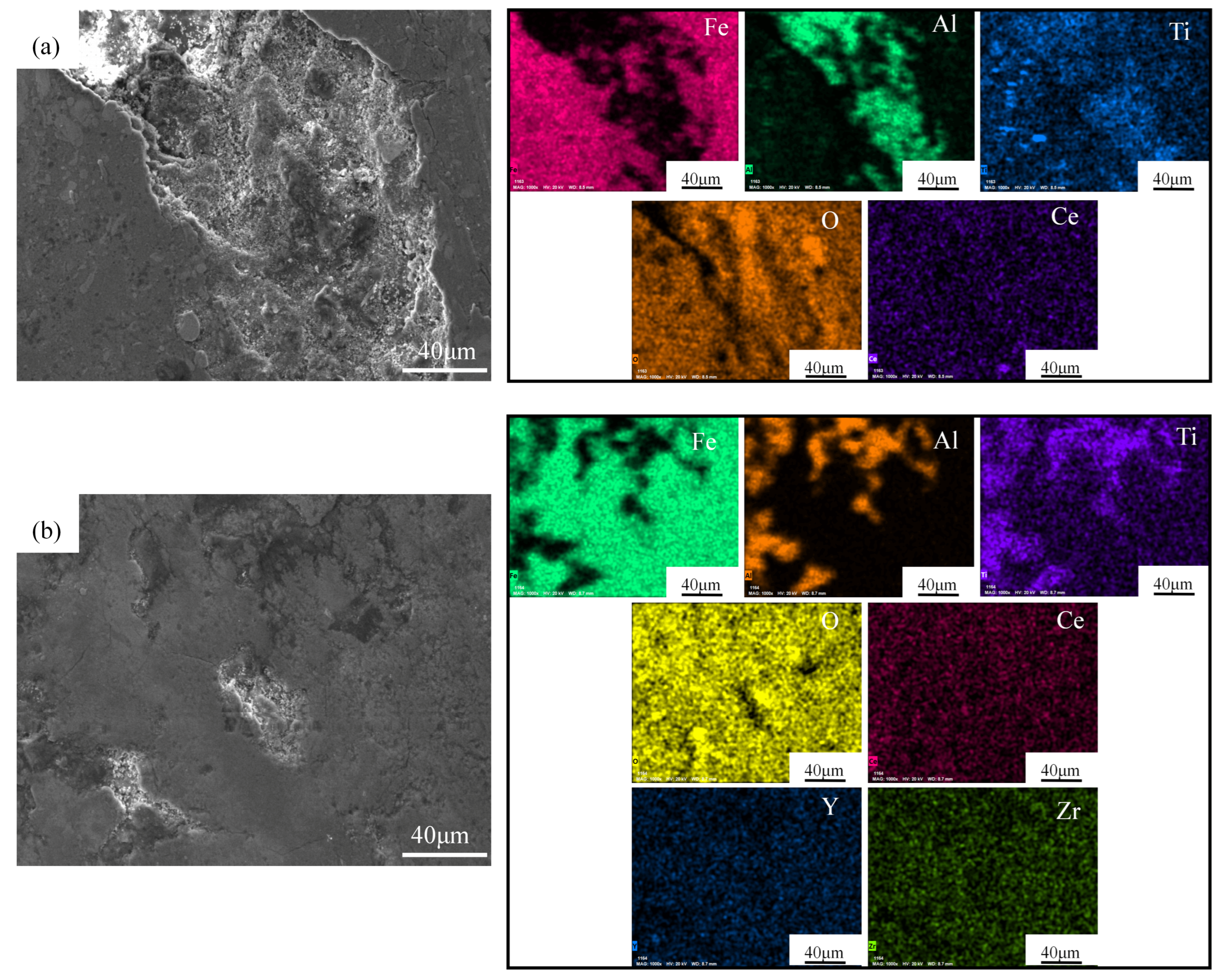
In order to further investigate the main wear mechanism of the coating, an EDS analysis was performed, as shown in Figure 12a,b. Fe is uniformly distributed in the MR zone, indicating that the metal elements in 45 steel have undergone material transfer to form a layer of oxide film, which is due to the friction process; the heat generated among the coating and the friction pair promotes the oxidation of the coating contact surface, and at the same time, the micro-convex body and spalling particles on the coating surface produce abrasive chips between the friction pairs, which are repeatedly rolled and tiled or embedded in the coating, while the abrasive chips are further oxidized to form a layer of oxide film protective coating. Al and Ti are concentrated in the NR region, which is due to the fact that the nano-agglomerate formed during plasma spraying is transferred to the uneven area with the wear test, which disperses the energy for the wear effect and avoids the stress concentration, thereby decreasing the influence on the wear of the coating. Ce is uniformly distributed in the coating, which is due to the fact that CeO2 has good chemical stability at high temperature and is not prone to phase transformation or reaction, so that it can stably exist at the grain boundary after high-temperature spraying, forming a uniformly distributed interfacial strengthening phase. At the same time, Zr and Y are evenly distributed in the ATC-6Y coating, forming more hard phases; this is because ZrO2 were added to enhance the compactness of the coating, refine the microstructure, reduce the coating porosity, cracks, and other defects, and further impede the extension of micro-cracks and the peeling of the coating. The high specific surface area of the nanoparticles also helps to provide an evenly distributed load, reducing local stresses during wear. With the addition of the bimodal structure and YSZ material, it is beneficial to reduce wear damage and improve wear resistance [49].
Figure 13a,b show the cross-sectional morphology of the ATC and ATC-6Y coating after wear, where the ATC coating has obvious wear spalling and cracks. However, the cracks and spalling of the ATC-6Y coating are significantly lower, and the addition of YSZ results in a significant enhancement of the coating’s toughness, while the ZrO2 phase reduces the degree of adhesive wear of the coating through micro-crack toughening during the friction process, and inhibits the cracks, keep spreading as the coating wear process [54]. To further illustrate the wear mechanism of the coating, a schematic diagram of the wear mechanism was established (Figure 13c). Due to the poor compactness of the ATC coating, with the reciprocating motion of the grinding ring, the contact point between the coating and the grinding ring forms an adhesive node due to the adhesion effect, so that part of the metal is dissociated and embedded in the coating, and it is continuously stretched with the particles near the pores by the relative motion of the grinding ring until it is withdrawn from the coating, so that fatigue cracks begin to germinate inside the coating, and the micro-cracks then expand and extend to the interior, and the free particles become abrasives to participate in the continuous friction and wear cycle, resulting in the peeling of the coating, so the wear degree of the ATC coating is more serious (Figure 13(c1: i–iv)). In contrast, the addition of YSZ gives the ATC-6Y coating a dense microstructure that acts at a shallower depth than the grinding ring (Figure 13(c2: i)). During the abrasion test, the toughening mechanism of YSZ hindered the propagation of micro-cracks (Figure 13(c2: iv)). The peeling phenomenon of the coating is clearly decreased, and the wear chips are repeatedly squeezed, torn, and gradually refined, and then they fall into the pits to make the wear surface of the coating smoother, thereby reducing the stress of the friction pair and reducing the degree of wear of the coating (Figure 13(c2: ii,iii)), so the ATC-6Y coating has a lower specific wear rate and good wear resistance.

4. Conclusions

Micron-scale Al2O3-TiO2-CeO2/YSZ agglomerated powder with a nanostructure was prepared by mechanical ball milling and spray-drying technology. It had a smooth surface, high sphericity, and good fluidity, and the phases of the agglomerated powder were composed of α-TiO2, γ-Al2O3, CeO2, and t-ZrO2. After the agglomerated powder was sintered at 1150 °C, the powder became denser and formed an α-Al2O3 phase. The ATC-6Y composite coating prepared by plasma spraying has a bimodal structure, with the presence of microstructured regions (MRs) in the fully molten and re-solidified regions and nanostructured regions (NRs) in the partially molten and solid sintered regions. The ATC-6Y coating phase is composed of α-Al2O3, γ-Al2O3, and t-ZrO2. The addition of YSZ resulted in the refinement of the coating grains with a size of 20.833 nm; the porosity is reduced to 2.89%, and the size of the spherical particles distributed on the surface is reduced. In the MR and NR region, Ti, Ce, Y, and other elements are uniformly distributed, and there is a tetragonal structure ZrO2 with a high melting point and low thermal conductivity in the NR region.
Compared with ATC coatings, ATC-6Y coatings have a significantly improved bond strength, toughness, and wear resistance. The bonding strength of the ATC coating was 23.3 MPa, the H/E and H3/E2 values were 0.0568 and 0.021, the volume loss was 1.05 mm3, the specific wear rate was 9.72 × 10⁻⁵ mm3·N−1·m−1, and the relative wear resistance was 2.83 times higher than that of the substrate. There is flake delamination and there are slight spalling pits on the wear surface of the ATC coating, and the wear mechanism is mainly fatigue wear and adhesive wear. The bonding strength of the ATC-6Y coating was 25.8 MPa, an increase of 10.7%, the H/E and H3/E2 values were 0.0589 and 0.035, the volume loss was 0.475 mm3, and the specific wear rate was 4.4 × 10⁻⁵ mm3·N−1·m−1, while the relative wear resistance is 6.3 times higher than that of the substrate and 2.2 times higher than that of the ATC coating. With the addition of YSZ in the coating, the generated ZrO2 phase reduces the degree of adhesive wear of the coating through micro-cracking toughening and inhibits the expansion of cracks in the coating wear process, while the wear mechanism of the coating is mainly slight adhesive wear and abrasive wear.

Author Contributions

S.L.: writing—original draft, investigation; J.M.: writing—review and editing, resources; B.C.: conceptualization, methodology; Z.X.: data curation; B.J.: validation; X.S.: supervision, project administration, funding acquisition. All authors have read and agreed to the published version of the manuscript.

Funding

This work was financially supported by the Natural Science Foundation of Shandong Province (project No. ZR2023KF024) and the Key Laboratory of Research on Hydraulic and Hydro-power Equipment Surface Engineering Technology of Zhejiang Province Laboratory Open Project (project No. 20240302).

Data Availability Statement

The data presented in this study are available on request from the corresponding author.

Conflicts of Interest

The authors declare that they have no known competing financial interests or personal relationships that could have appeared to influence the work reported in this paper.

References

  1. Bolelli, G.; Steduto, D.; Kiilakoski, J.; Varis, T.; Lusvarghi, L.; Vuoristo, P. Tribological properties of plasma sprayed Cr2O3, Cr2O3-TiO2, Cr2O3-Al2O3 and Cr2O3-ZrO2 coatings. Wear 2021, 480, 203931. [Google Scholar] [CrossRef]
  2. Testa, V.; Morelli, S.; Bolelli, G.; Usvarghi, L.; Björklund, S.; Joshi, S. Micromechanical behaviour and wear resistance of hybrid plasma-sprayed TiC reinforced Tribaloy-400. Surf. Coat. Technol. 2021, 425, 127682. [Google Scholar] [CrossRef]
  3. Zhang, X.; Wang, Y.W.; Sun, W.W.; Yang, Y.; Zhang, C.; Ma, Y.D.; Cui, Y.H.; Zhao, C.C.; Wang, L.; Dong, Y.C.; et al. Microstructure and properties of Al2O3-ZrO2-Y2O3 composite coatings prepared by plasma spraying. J. Therm. Spray Technol. 2020, 29, 967–978. [Google Scholar] [CrossRef]
  4. Mao, J.Y.; Liu, M.; Deng, C.M.; Mao, J.; Zeng, D.C. A comparative study of spray-dried and mechanically-mixed ZrB2-MoSi2 composite coatings fabricated by low pressure plasma spray. Rare Met. Mat. Eng. 2016, 45, 1386–1390. [Google Scholar] [CrossRef]
  5. Wang, H.B.; Lu, H.; Song, X.Y.; Yan, X.F.; Liu, X.M.; Nie, Z.R. Corrosion resistance enhancement of WC cermet coating by carbides alloying. Corros. Sci. 2019, 147, 372–383. [Google Scholar] [CrossRef]
  6. Matikainen, V.; Bolelli, G.; Koivuluoto, H.; Sassatelli, P.; Lusvarghi, L.; Vuoristo, P. Sliding wear behaviour of HVOF and HVAF sprayed Cr3C2-based coatings. Wear 2017, 388, 57–71. [Google Scholar] [CrossRef]
  7. Zhang, Y.G.; Gao, X.F.; Liang, X.B.; Chong, K.; Wu, D.T.; Zou, Y. Effect of laser remelting on the microstructure and corrosion property of the arc-sprayed AlFeNbNi coatings. Surf. Coat. Technol. 2020, 398, 126099. [Google Scholar] [CrossRef]
  8. Nayak, S.K.; Kumar, A.; Pathak, A.; Banerjee, A.; Laha, T. Multi-scale mechanical properties of Fe-based amorphous/nanocrystalline composite coating synthesized by HVOF spraying. J. Alloys Compd. 2020, 825, 154120. [Google Scholar] [CrossRef]
  9. Senthilkumar, N.; Perumal, G.; Palanikumar, K.; Deepanraj, B.; Shameer Basha, M. Wear and mechanical characteristics of coated Ti-6Al-4 V alloy with an alumina-13 wt.% titania -40 wt.% yitrium stabilized zirconia ceramic composite via plasma spraying technique. Results Eng. 2025, 25, 103777. [Google Scholar] [CrossRef]
  10. Karagedov, G.R.; Lyakhov, N.Z. Preparation and sintering of nanosized α-Al2O3 powder. Nanostructured Mater. 1999, 11, 559–572. [Google Scholar] [CrossRef]
  11. Wang, Y.; Guo, Y.G.; Zhang, Q. Study on tribological properties and process optimization of Al2O3-xTiO2 composite coatings prepared by plasma spraying. Mater. Today Commun. 2025, 44, 112182. [Google Scholar] [CrossRef]
  12. Xue, Z.L.; Zhu, Y.; Yu, H.Y.; Shi, M.C.; Liu, X.; Zhang, S.H. Nano-agglomerated powder and thermal shock cycling property of 8YSZ nano-structured thermal barrier coating. Surf. Coat. Technol. 2022, 433, 128173. [Google Scholar] [CrossRef]
  13. Li, G.R.; Yang, G.J. Understanding of degradation-resistant behavior of nanostructured thermal barrier coatings with bimodal structure. J. Mater. Sci. Technol. 2019, 35, 231–238. [Google Scholar] [CrossRef]
  14. Wang, L.; Wang, Y.; Sun, X.G.; He, J.Q.; Pan, Z.Y.; Wang, C.H. Microstructure and indentation mechanical properties of plasma sprayed nano-bimodal and conventional ZrO2–8wt% Y2O3 thermal barrier coatings. Vacuum 2012, 86, 1174–1185. [Google Scholar] [CrossRef]
  15. Masanta, M.; Ganesh, P.; Kaul, R.; Nath, A.K.; Choudhury, A.R. Development of a hard nano-structured multi-component ceramic coating by laser cladding. Mater. Sci. Eng. A 2009, 508, 134–140. [Google Scholar] [CrossRef]
  16. Li, W.Z.; Zhu, Y.P.; Wang, X.Y.; Zhao, L.L.; Chu, Y.; Chen, F.H.; Chang, G.; Fang, S.G. Preparation and thermophysical properties of new multi-component entropy-stabilized oxide ceramics for thermal barrier coatings. Coatings 2023, 13, 937. [Google Scholar] [CrossRef]
  17. Carnicer, V.; Orts, M.J.; Moreno, R.; Sánchez, E. Microstructure assessment of suspension plasma spraying coatings from multicomponent submicronic Y-TZP/Al2O3/SiC particles. Ceram. Int. 2018, 44, 12014–12020. [Google Scholar] [CrossRef]
  18. Jia, S.K.; Yong, Z.; Xu, J.Y.; Wang, J.; Yu, L. Effect of TiO2 content on properties of Al2O3 thermal barrier coatings by plasma spraying. Trans. Nonferrous Met. Soc. China 2015, 25, 175–183. [Google Scholar] [CrossRef]
  19. Brar, S.S.; Brar, G.S.; Chawla, V. Characterization of D-gun sprayed Al2O3-13% TiO2 and Al2O3-40% TiO2 coatings on ASTM 316 boiler steel and their microstructure. Mater. Today Proc. 2022, 50, 2299–2306. [Google Scholar] [CrossRef]
  20. Zhang, Y.; Sun, S.L.; Zhao, L.; Yang, C.D.; Wu, L.P.; Guo, Y.J.; Ang, S.M. Corrosion Behavior of Plasma-Sprayed Al2O3-3% TiO2 Coatings Doped with CeO2. J. Therm. Spray Technol. 2023, 32, 290–305. [Google Scholar] [CrossRef]
  21. Yang, C.D. Study on Microstructure and Properties of Plasma Sprayed Al2O3/TiO2-CeO2 Composite Coating. Master’s Thesis, Shenyang University, Shenyang, China, 2021. [Google Scholar] [CrossRef]
  22. Hebbale, A.; Ramesh, M.R.; Petru, J.; Chandramouli, T.V.; Srinath, M.S.; Shetty, R.K. A microstructural study and high-temperature oxidation behaviour of plasma sprayed NiCrAlY based composite coatings. Results Eng. 2025, 25, 103926. [Google Scholar] [CrossRef]
  23. Shi, T.J.; Bai, B.T.; Peng, H.R.; Yuan, K.; Han, R.F.; Zhou, Q.; Pang, X.X.; Zhang, X.; Yan, Z. Improved thermal shock resistance of GYYZO-YSZ double ceramic layer TBCs induced by induction plasma spheroidization. Surf. Coat. Technol. 2024, 77, 130372. [Google Scholar] [CrossRef]
  24. Luțcanu, M.; Cimpoeșu, R.; Abrudeanu, M.; Munteanu, C.; Moga, S.G.; Coteata, M.; Zegan, G.; Benchea, M.; Cimpoeșu, N.; Murariu, A.M. Mechanical Properties and Thermal Shock Behavior of Al2O3-YSZ Ceramic Layers Obtained by Atmospheric Plasma Spraying. Crystals 2023, 13, 614. [Google Scholar] [CrossRef]
  25. Mehar, S.; Sapate, S.G. Contact severity maps for plasma sprayed YSZ modified Al2O3-3% TiO2 coatings. Ceram. Int. 2024, 50, 13003–13013. [Google Scholar] [CrossRef]
  26. Wang, C.; Pang, X.J.; Gao, Z.H.; Liu, J.N.; Fang, Y.C.; Cui, X.F.; Liu, E.B.; Jin, G. Wear Resistance of YSZ Fibers Reinforced Al2O3/8YSZ Coatings Prepared by Atmosphere Plasma Spraying. J. Mater. Rep. 2018, 32, 563–568. [Google Scholar] [CrossRef]
  27. Zeng, Y.B.; Liu, Y.Z.; Zhang, Y.X.; Zhou, Z.G.; Liu, X.H. Ferroelastic domain switching toughening in Ce-Y-La co-stabilized zirconia ceramics obtained from coated starting powders. J. Alloys Compd. 2020, 820, 153177. [Google Scholar] [CrossRef]
  28. Guan, H.; Gong, X.J.; Liu, R.; Liu, Y. Preparation of Stable Nanosized ZrO2 Particles with Different Crystallographic Structures. Chin. J. Mater. Res. 2014, 28, 139–143. [Google Scholar] [CrossRef]
  29. Kumar, R.; Goyal, K.; Bhandari, D. Slurry Erosion Behavior of Thermally Sprayed Nano YSZ Reinforced WC-10Co-4Cr Ceramic Nanocomposite Coatings. Tribol. Trans. 2023, 66, 47–58. [Google Scholar] [CrossRef]
  30. Zhao, X.L.; Liu, W.; Li, C.; Yan, G.; Wang, Q.W.; Li, Y.; Zhou, Y.C. Solid particle erosion behavior of La2Ce2O7/YSZ double-ceramic-layer and traditional YSZ thermal barrier coatings at high temperature. Coatings 2022, 12, 1638. [Google Scholar] [CrossRef]
  31. An, G.S.; Li, W.S.; Li, F.; Cheng, B.; Wang, Z.P.; Li, Z.Y.; Zhang, Y. Isothermal oxidation and TGO growth behaviors of YAG/YSZ double-ceramic-layer thermal barrier coatings. Ceram. Int. 2021, 47, 24320–24330. [Google Scholar] [CrossRef]
  32. Liu, L.; Maeda, K.; Onda, T.; Chen, Z.C. Effect of YSZ with different Y2O3 contents on toughening behavior of Al2O3/Ba-β-Al2O3/ZrO2 composites. Ceram. Int. 2019, 45, 18037–18043. [Google Scholar] [CrossRef]
  33. Meng, Z.C.; Qian, W.F.; Ning, B.K.; Wang, S.; Chen, Y.N.; Zhang, Y.; Wang, N.; Li, Y.C.; Zhang, W.; Gao, G.R. High-temperature crack resistance of yttria-stabilized zirconia coatings enhanced by interfacial stress transfer. J. Appl. Surf. Sci. 2025, 682, 161688. [Google Scholar] [CrossRef]
  34. Sanjai, S.G.; Srideep, S.; Krishna, B.A.; Sumanth, M.S.; Ramaswamy, P. Synthesis of yttria-stabilized zirconia nano powders for plasmasprayed nano coatings. Mater. Today Proc. 2019, 22, 1253–1263. [Google Scholar] [CrossRef]
  35. Padture, N.P.; Gell, M.; Jordan, E.H. Thermal barrier coatings for gas-turbine engine applications. Science 2002, 296, 280–284. [Google Scholar] [CrossRef]
  36. Carpio, P.; Borrell, A.; Salvador, M.D.; Gómez, A.; Martínez, E.; Sánchez, E. Microstructure and mechanical properties of plasma spraying coatings from YSZ feedstocks comprising nano- and submicron-sized particles. Ceram. Int. 2015, 41, 4108–4117. [Google Scholar] [CrossRef]
  37. Vicent, M.; Bannier, E.; Moreno, R.; Salvador, M.D.; Sánchez, E. Atmospheric plasma spraying coatings from alumina–titania feedstock comprising bimodal particle size distributions. J. Eur. Ceram. Soc. 2013, 33, 3313–3324. [Google Scholar] [CrossRef]
  38. Loghman-Estarki, M.R.; Edris, H.; Jamali, H.; Ghasemi, R.; Pourbafrany, M.; Erfanmanesh, M.; Ramezani, M. Spray drying of nanometric SYSZ powders to obtain plasma sprayable nanostructured granules. Ceram. Int. 2013, 39, 9447–9457. [Google Scholar] [CrossRef]
  39. Gao, Y. Study of the Microstructure and Properties of Plasma-Sprayed Al2O3-TiO2-ZrO2 Coating. Master’s Thesis, Tianjin Hebei University of Technology, Tianjin, China, 2009. [Google Scholar]
  40. GB/T 8642-2002; Thermal Spraying—Determination of Tensile Adhesive Strength. China Standards Press: Beijing, China, 2002.
  41. Mcpherson, R. Formation of Metastable Phase in Flame and Plasma Prepared Alumina. J. Mater. Sci. 1973, 8, 851–858. [Google Scholar] [CrossRef]
  42. Lu, F.Z.; Liu, H.T.; Huang, W.Z. A Review of 8YSZ-Al2O3Composite Thermal Barrier Coatings. J. Mater. Rep. 2021, 35, 7042–7047+7070. [Google Scholar] [CrossRef]
  43. Rong, J.; Yang, K.; Zhao, H.Y.; Liu, C.G.; Zhuang, Y.; Tao, S.Y. Tribological performance of plasma sprayed Al2O3–Y2O3 composite coatings. Surf. Coat. Technol. 2016, 302, 487–494. [Google Scholar] [CrossRef]
  44. Mehar, S.; Sapate, S.G.; Vashishtha, N.; Rathod, A.; Bagde, P. Tribological performance of plasma sprayed Al2O3-TiO2-ZrO2 ceramic coating. Mater. Today Proc. 2021, 45, 4737–4741. [Google Scholar] [CrossRef]
  45. Yang, S.Y.; Xing, X.G.; Zhang, J.J.; Wang, H.; Si, M.L.; Wang, H.F. Influence of rare earth oxide (REO) additives on mechanical and friction and wear properties of aluminum oxide ceramics. J. Funct. Mater. 2018, 49, 6190–6195+6200. [Google Scholar] [CrossRef]
  46. Liu, J.L.; Wu, R.; Zu, Y.D.; Xiao, J.S.; Zhang, B.; Zou, H.J. Crystalline Size of TiO2 at Calcination Temperature with by RietveldRef inement, Debye-Scherrer and Williamson-Hall Method. Chem. Eng. Manag. 2023, 13, 151–155. [Google Scholar] [CrossRef]
  47. Sui, Y.D.; Han, L.N.; Jiang, Y.H. Effect of Ta2O5 addition on the microstructure and mechanical properties of TiO2-added yttria-stabilized zirconia-toughened alumina (ZTA) composites. Ceram. Int. 2018, 44, 14811–14816. [Google Scholar] [CrossRef]
  48. Li, R.B.; Xing, Y.; Zhang, Z.X.; He, F. Plasma Spraying Process of YSZ Thermal Barrier Coatings. J. Surf. Technol. 2024, 53, 217–229. [Google Scholar] [CrossRef]
  49. Kushwaha, S.; Bhadauria, A.; Bajpai, S.; Tiwari, A.; Pandey, K.K.; Keshri, A.K.; Balani, K. Mechanical, microstructural, and fretting wear behaviour of Al2O3–ZrO2-CNT based bimodal composite coatings. Wear 2023, 532, 205127. [Google Scholar] [CrossRef]
  50. Bogicevic, A.; Wolverton, C.; Crosbie, G.M.; Stechel, E.B. Defect ordering in aliovalently doped cubic zirconia from first principles. Phys. Rev. B 2001, 64, 014106. [Google Scholar] [CrossRef]
  51. Leyland, A.; Matthews, A. On the significance of the H/E ratio in wear control: A nanocomposite coating approach to optimised tribological behaviour. Wear 2000, 246, 1–11. [Google Scholar] [CrossRef]
  52. Severo, F.D.S.; Scheuer, C.J.; Cardoso, R.P.; Brunatto, S.F. Cavitation erosion resistance enhancement of martensitic stainless steel via low-temperature plasma carburizing. Wear 2019, 428, 162–166. [Google Scholar] [CrossRef]
  53. Zhao, X.; An, Y.; Chen, J.; Zhou, H.; Yin, B. Properties of Al2O3–40 wt.% ZrO2 composite coatings from ultra-fine feedstocks by atmospheric plasma spraying. Wear 2008, 265, 1642–1648. [Google Scholar] [CrossRef]
  54. Gasson, P.C. Materials Sciences and Engineering–Eighth edition. WD Callister and DG Rethwisch John Wiley and Sons, The Atrium, Southern Gate, Chichester, West Sussex, PO19 8SQ, UK. 2010. 968pp. Illustrated.£ 47.99. ISBN 978-0-470-50586-1. Aeronaut. J. 2011, 115, 388–389. [Google Scholar] [CrossRef]
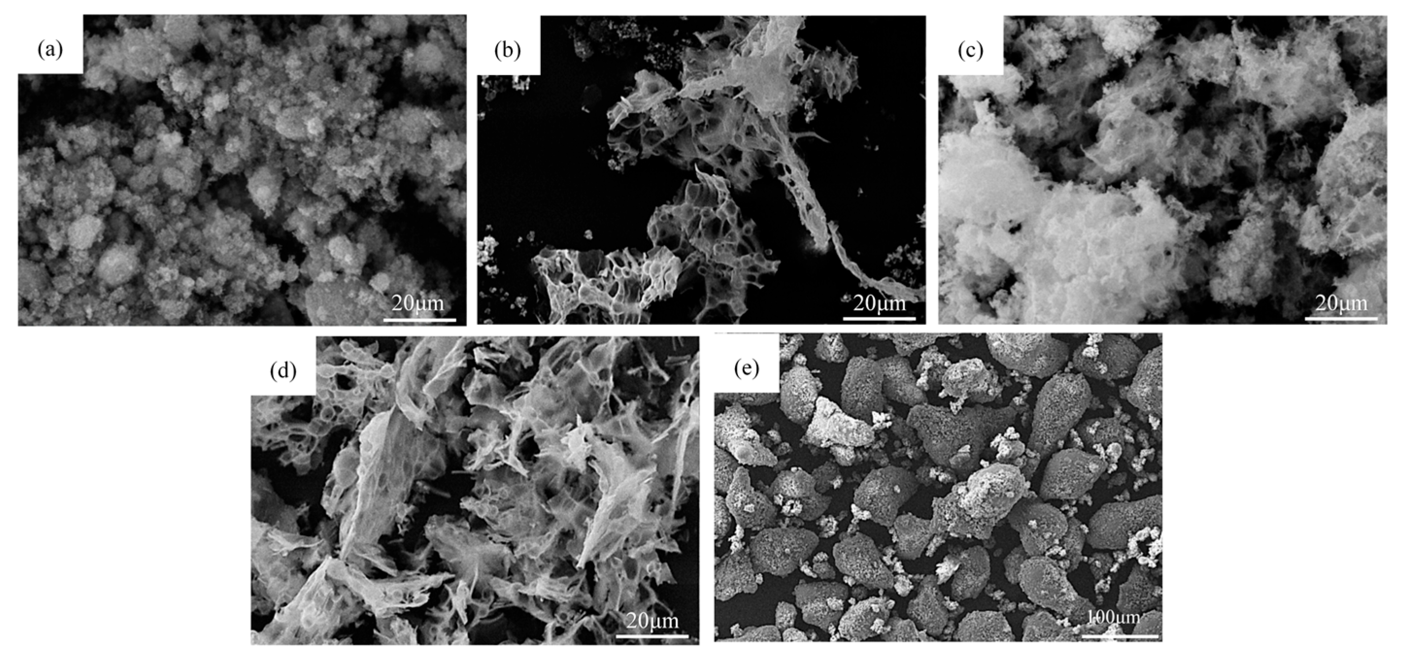
Figure 1. Microscopic morphology of the original nano-powder: (a) Al2O3; (b) TiO2; (c) CeO2; (d) YSZ; (e) NiCrAlY.
Coatings 15 01164 g001
Figure 2. Schematic diagram of the coating preparation process: (a) mechanical ball milling; (b) spray drying; (c) high-temperature sintering; (d) atmospheric plasma sparing.
Coatings 15 01164 g002
Figure 3. (a) ATC-6Y powder morphology before sintering; (b) partial magnification in (a); (c) EDS analysis; (d) ATC-6Y powder morphology after sintering; (e) partial magnification in (d); (f) EDS analysis.
Coatings 15 01164 g003
Figure 4. (a) XRD diffraction patterns of nano-agglomerated powder before and after sintering; (b) coating XRD diffraction pattern; (c) schematic diagram of the microstructural changes from powder to coating in ATC and ATC-6Y systems.
Coatings 15 01164 g004
Figure 5. (a) Backscatter electron diagram of ATC-6Y coating; (b) EDS analysis at grain boundaries; (c) EDS analysis at crystal planes.
Coatings 15 01164 g005
Figure 6. (a) Cross-sectional morphology of ATC coating; (b) pore distribution diagram; (c) ATC-6Y coated cross-section; (d) pore distribution map.
Coatings 15 01164 g006
Figure 7. (a) Surface topography of ATC coating; (b) morphology of medium-like spherical particles in (a); (c) EDS spot scanning of particle; (d) surface topography of ATC-6Y coating; (e) morphology of medium-like spherical particles in (d); (f) EDS spot scanning of particle.
Coatings 15 01164 g007
Figure 8. (a) Morphology of MR and NR regions of ATC-6Y coating; (b) EDS surface scan of element; (c) energy spectrum analysis.
Coatings 15 01164 g008
Figure 9. (a) TEM image of the ATC-6Y coating; (b) HR-TEM image of zone “A” in (a); (c,d) SAED pattern of zone “A” in (a); (e) IFFT image of zone “B” in (b); (f) IFFT image of zone “C” in (b).
Coatings 15 01164 g009
Figure 10. (a) Coating bond strength; (b) load–displacement curves.
Coatings 15 01164 g010
Figure 11. (a) Coating friction coefficient curve; (b) coating volume loss, specific wear rate, and relative wear resistance; (c) wear topography of ATC coating surfaces; (d) wear topography of ATC-6Y coating surfaces.
Coatings 15 01164 g011
Figure 12. Wear coating surface scanning: (a) ATC; (b) ATC-6Y.
Coatings 15 01164 g012
Figure 13. (a) Wear cross-section morphology of ATC coating; (b) wear cross-section morphology of ATC-6Y coating; (c) schematic of wear mechanism of both coatings.
Coatings 15 01164 g013
Table 1. Plasma spraying process parameters.
ParametersNiCrAlY Bond CoatingATC/ATC-6Y Composite Coating
Spraying current (A)450600
Spraying voltage (V)6070
Main gas Ar flow rate (L/min)4242
Secondary gas H2 flow rate (L/min)1010
Gun moving speed (mm/s)400400
Spraying distance (mm)110110
Powder feed rate (g/min)3511
Table 2. Parameters and results of coating grain size calculation.
Coating2θ (°)FWHMβ (rad)D (nm)
ATC45.6680.3290.0057426.200 ± 1.2
ATC-6Y45.8790.4140.0072320.833 ± 1.0
Table 3. Mechanical parameters of the coatings based on nano-indentation curves.
SamplesH (GPa)E (GPa)H/EH3/E2
ATC6.46113.80.05680.021
ATC-6Y9.96169.10.05890.035
Disclaimer/Publisher’s Note: The statements, opinions and data contained in all publications are solely those of the individual author(s) and contributor(s) and not of MDPI and/or the editor(s). MDPI and/or the editor(s) disclaim responsibility for any injury to people or property resulting from any ideas, methods, instructions or products referred to in the content.